Embed Size (px)
DESCRIPTION
Induction Motor 1
Citation preview
3-phase Induction motor
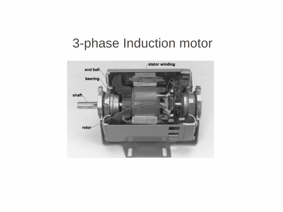
3-Phase Induction Motor
Most Common & Frequent motors in industry
Simple Design, Rugged, Low Cost and Easy to Maintain
High efficiency: no brushes and good power factor
Constant speed from zero to full load
Transformer: Electrical Magnetic Electrical Alternating field
Induction Motor: Electrical Magnetic Mechanical /Electrical
Rotating field
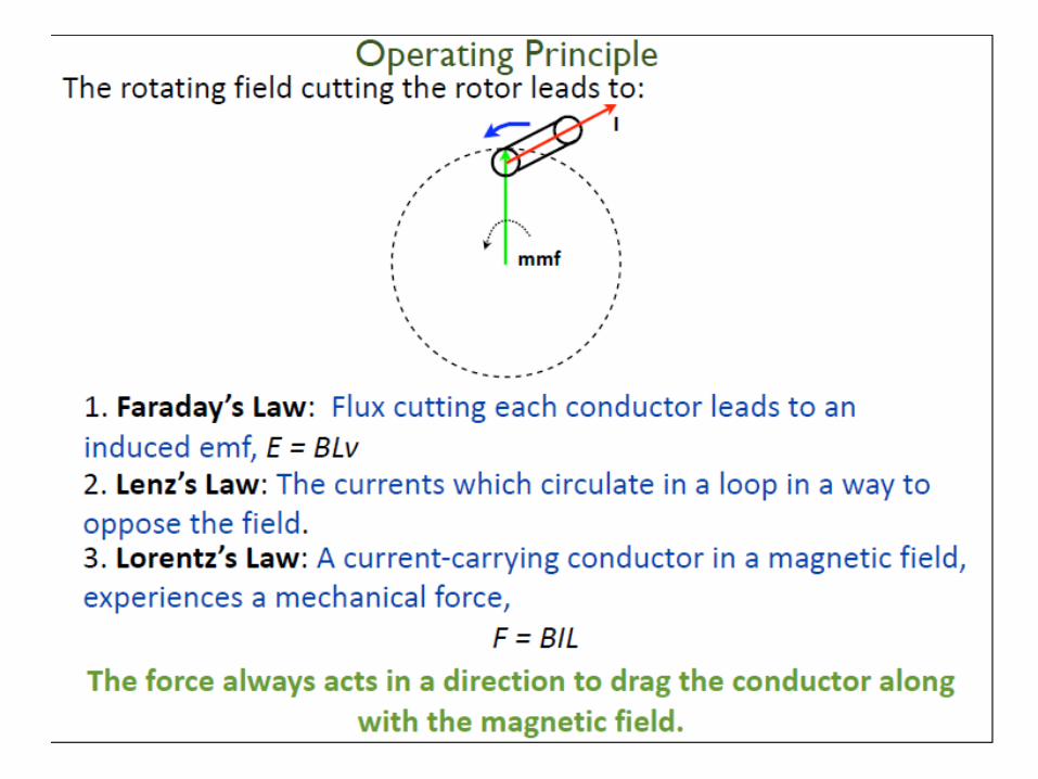
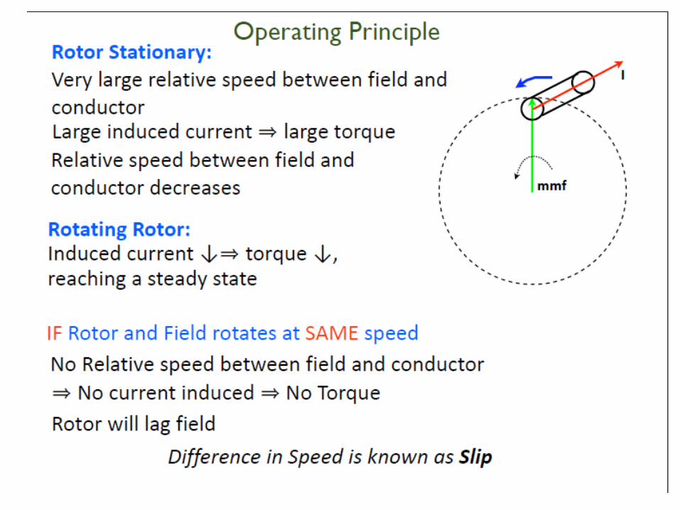
General Principle
Wide Range of power rating: fractional horsepower to MW

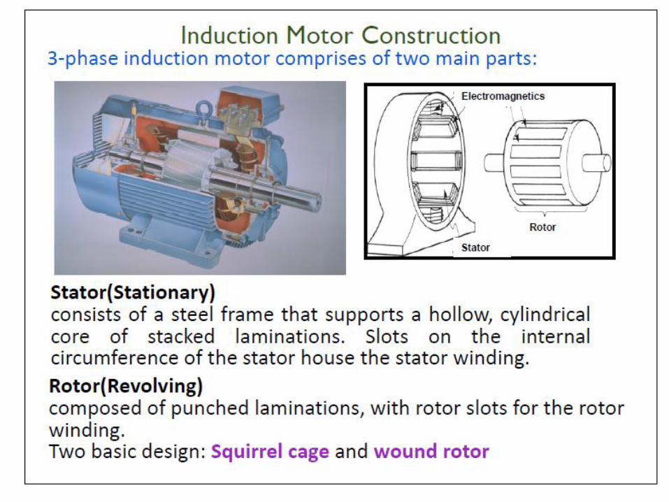
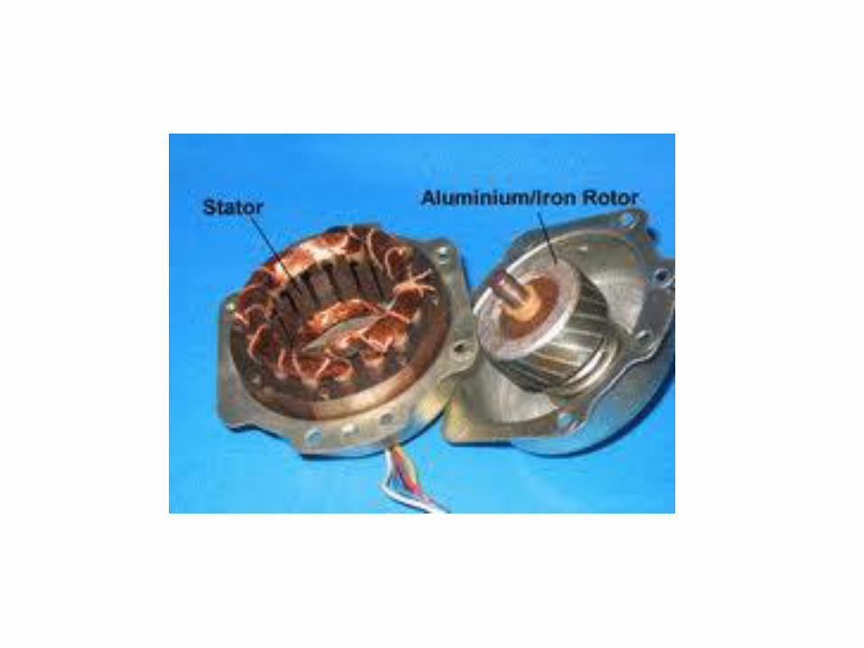
Induction Motor Construction
3-phase induction motor comprises of two main parts:
Stator(Stationary)consists of a steel frame that supports a hollow, cylindrical core of stacked laminations.Slots on the internal circumference of the stator house the stator winding.
Rotor(Revolving)composed of punched laminations, with rotor slots for the rotor winding.Two basic design: Squirrel cage and wound rotor
Electromagnetics
Stator
Rotor
A
B
C
IA
IB
IC
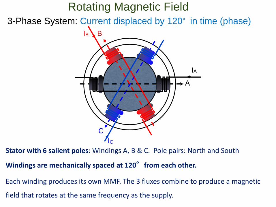
Rotating Magnetic Field
Stator with 6 salient poles: Windings A, B & C. Pole pairs: North and South
Windings are mechanically spaced at 120°from each other.
Each winding produces its own MMF. The 3 fluxes combine to produce a magnetic
field that rotates at the same frequency as the supply.
3-Phase System: Current displaced by 120°in time (phase)
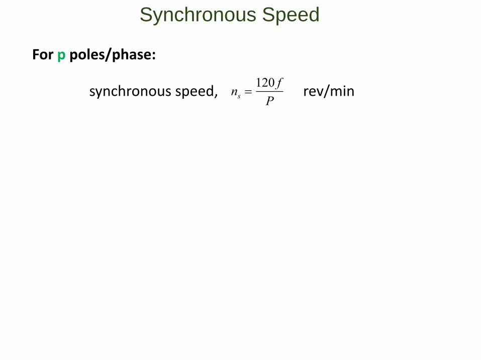
Synchronous Speed
For p poles/phase:
synchronous speed, ns 120 f
Prev/min
sn
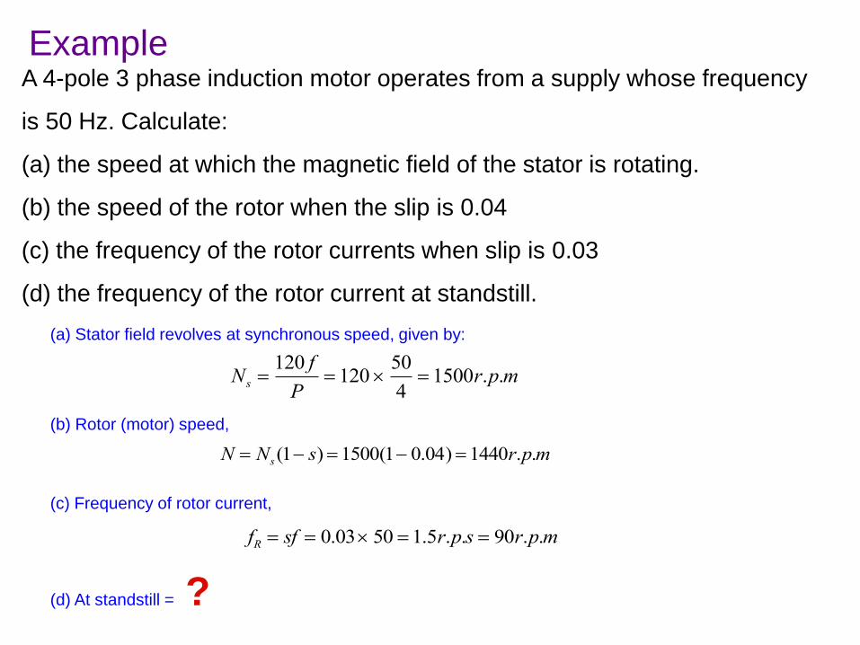
ExampleA 4-pole 3 phase induction motor operates from a supply whose frequency
is 50 Hz. Calculate:
(a) the speed at which the magnetic field of the stator is rotating.
(b) the speed of the rotor when the slip is 0.04
(c) the frequency of the rotor currents when slip is 0.03
(d) the frequency of the rotor current at standstill.
(a) Stator field revolves at synchronous speed, given by:
Ns 120 f
P 120
50
4 1500r.p.m
(b) Rotor (motor) speed,
N Ns(1 s) 1500(1 0.04) 1440r.p.m
(c) Frequency of rotor current,
fR sf 0.03 50 1.5r.p.s 90r.p.m
(d) At standstill = ?
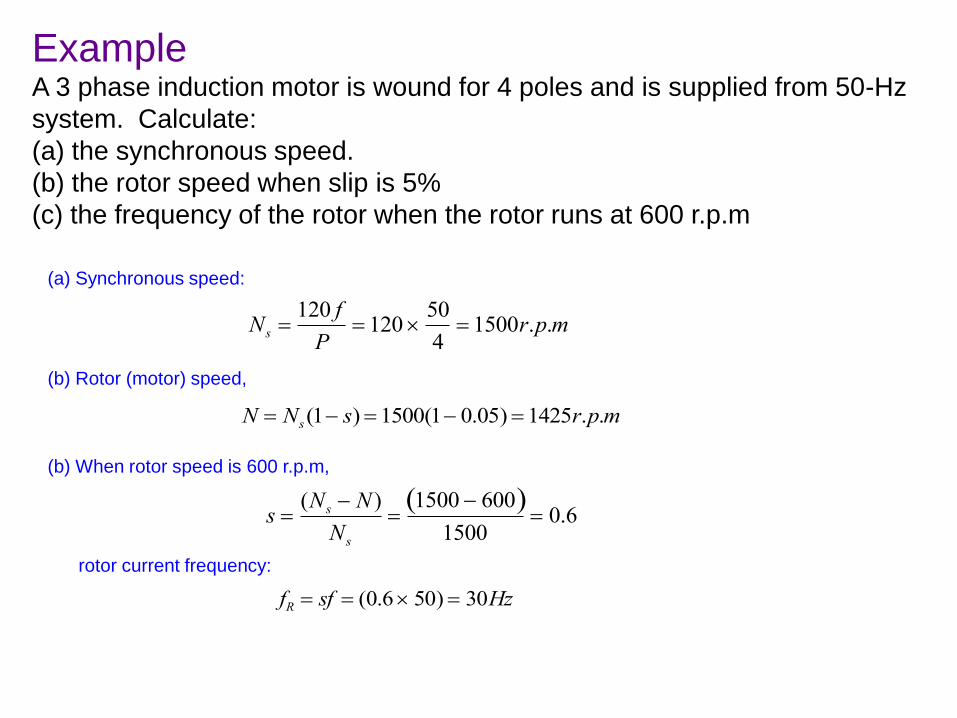
ExampleA 3 phase induction motor is wound for 4 poles and is supplied from 50-Hz
system. Calculate:
(a) the synchronous speed.
(b) the rotor speed when slip is 5%
(c) the frequency of the rotor when the rotor runs at 600 r.p.m
(a) Synchronous speed:
Ns 120 f
P 120
50
4 1500r.p.m
(b) Rotor (motor) speed,
N Ns(1 s) 1500(1 0.05) 1425r.p.m
(b) When rotor speed is 600 r.p.m,
s (Ns N )
Ns1500 600 1500
0.6
rotor current frequency:
fR sf (0.6 50) 30Hz
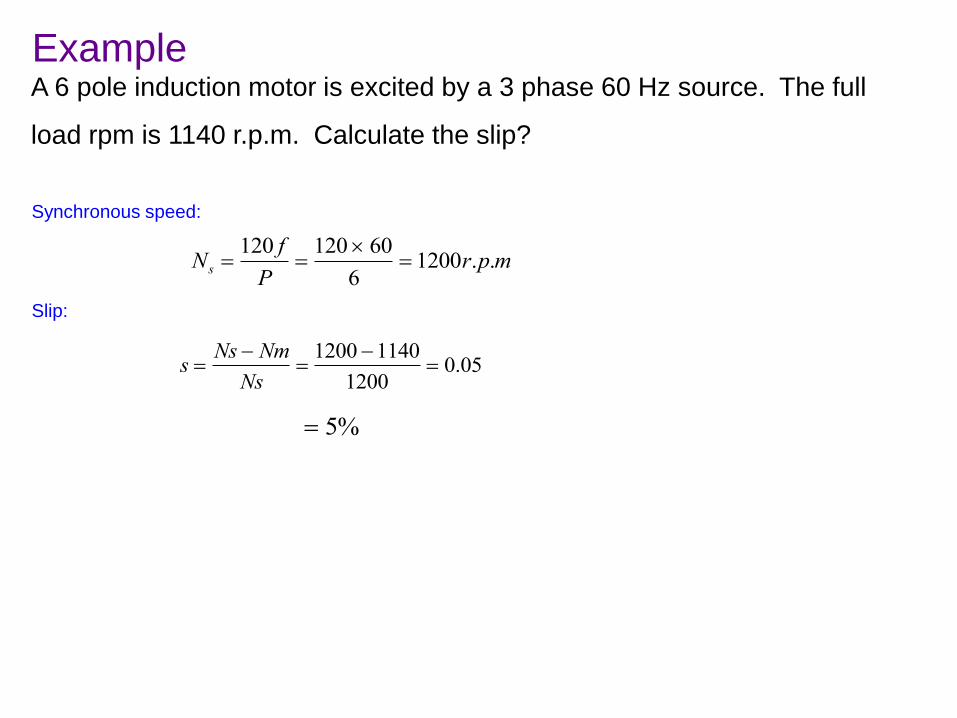
ExampleA 6 pole induction motor is excited by a 3 phase 60 Hz source. The full
load rpm is 1140 r.p.m. Calculate the slip?
Synchronous speed:
Ns 120 f
P120 60
6 1200r.p.m
Slip:
s Ns Nm
Ns1200 1140
1200 0.05
5%
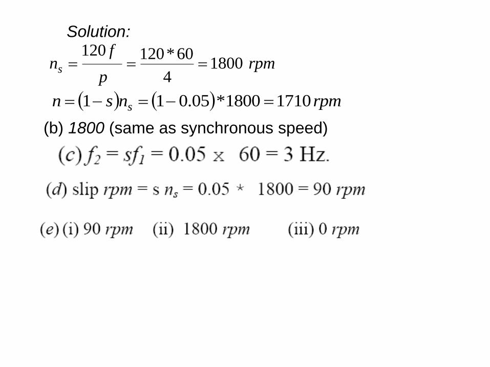
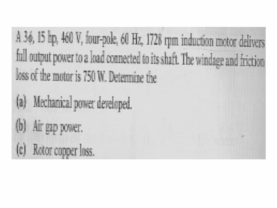
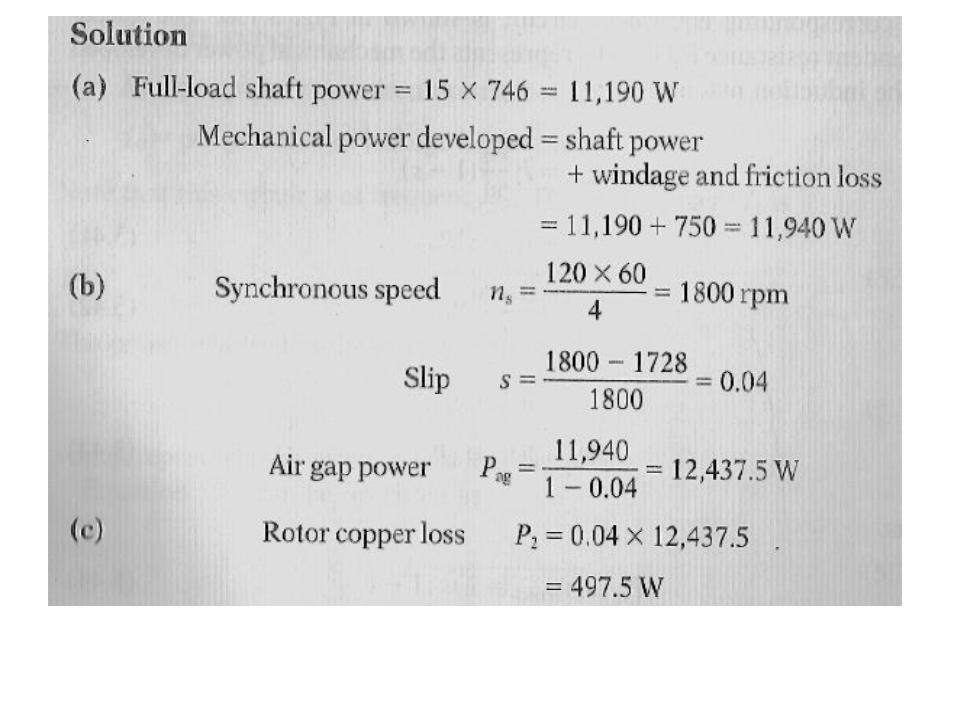
Solution:
rpmp
fns 1800
4
60*120120
rpmnsn s 17101800*05.011
(b) 1800 (same as synchronous speed)
A 4-pole 3-phase induction motor operates from a supply whose frequency is 50Hz. Calculate:1. The speed at which the magnetic field of the stator is rotating2. The speed of the rotor when the slip is 0.043. The frequency of the rotor currents when the slip is 0.034. The frequency of the rotor currents at standstill.
Example
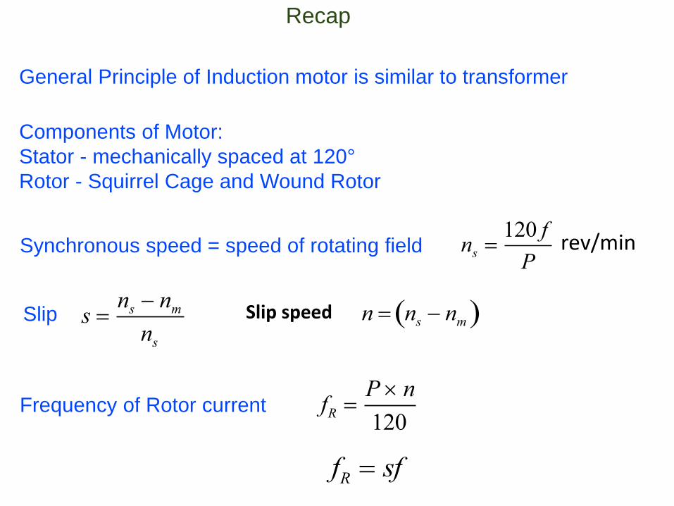
Recap
General Principle of Induction motor is similar to transformer
Components of Motor:
Stator - mechanically spaced at 120°
Rotor - Squirrel Cage and Wound Rotor
Synchronous speed = speed of rotating field ns 120 f
Prev/min
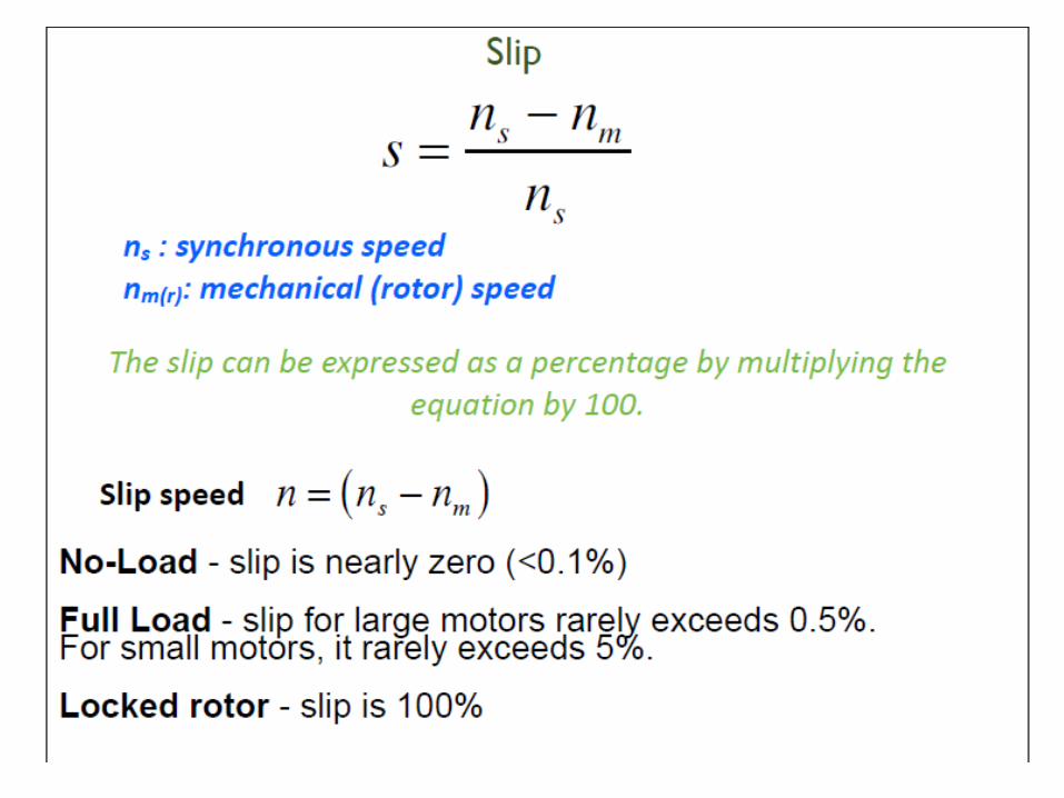
Slip s ns nm
ns
Slip speed n ns nm
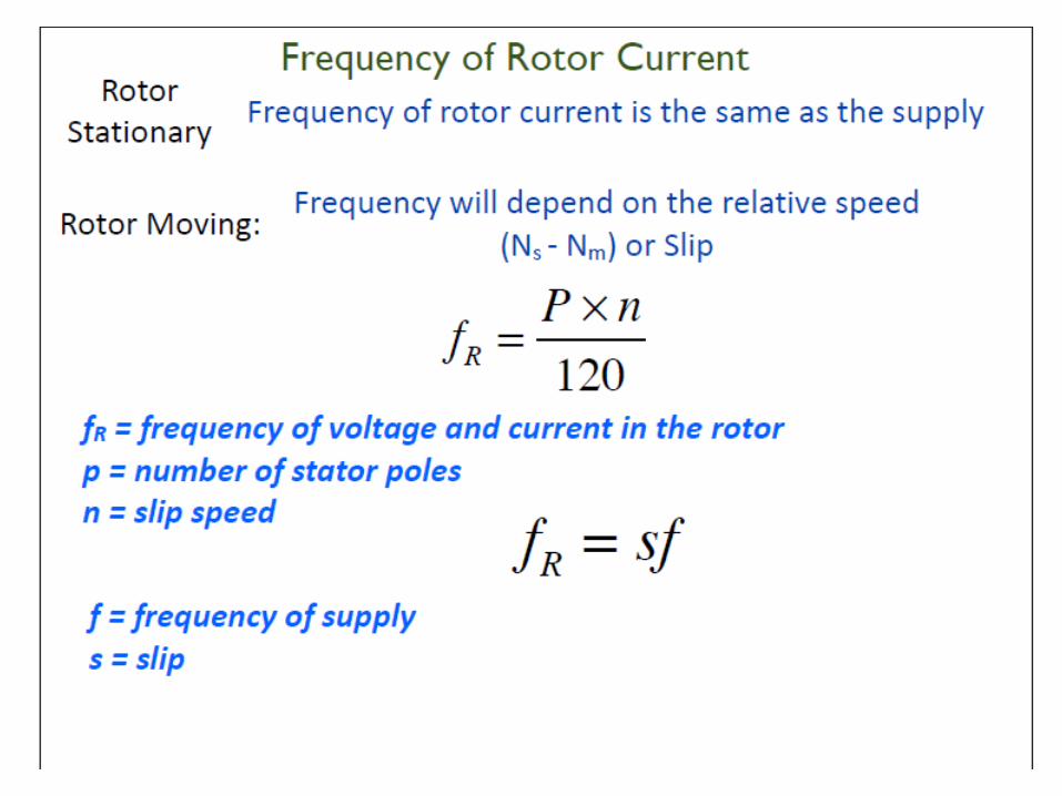
Frequency of Rotor current fR P n
120
fR sf
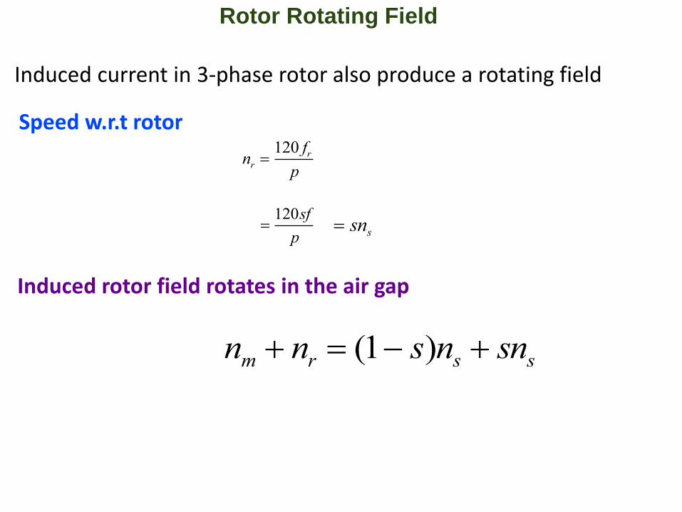
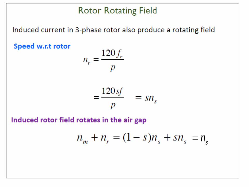
Rotor Rotating Field
nr 120 fr
p
120sf
p sns
Induced current in 3-phase rotor also produce a rotating field
Speed w.r.t rotor
Induced rotor field rotates in the air gap
nm nr (1 s)ns sns
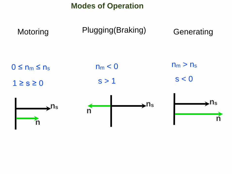
Modes of Operation
Motoring Plugging(Braking) Generating
0 ≤ nm ≤ ns
1 ≥ s ≥ 0
nm < 0
s > 1
nm > ns
s < 0
n
nn
ns ns ns
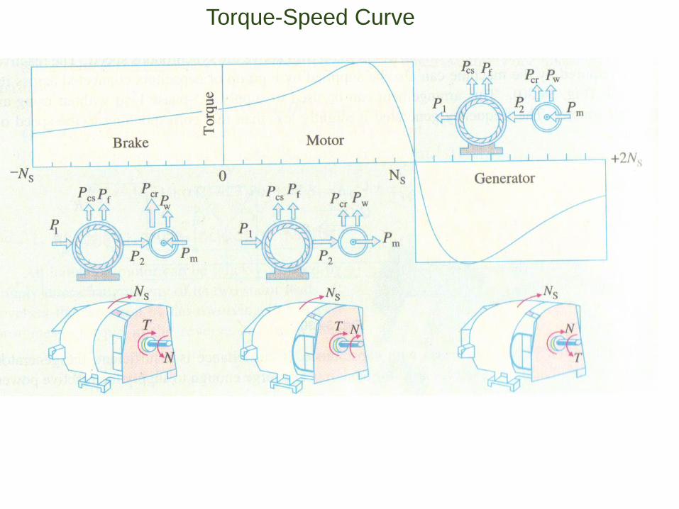
Torque-Speed Curve
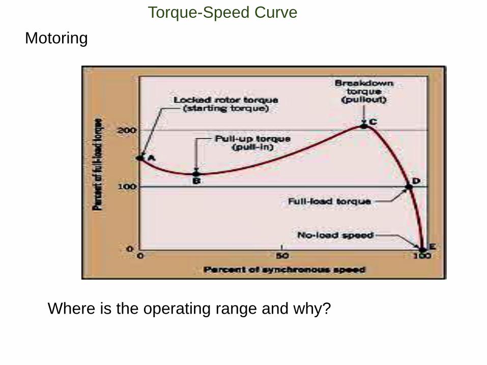
Torque-Speed Curve
Motoring
Where is the operating range and why?
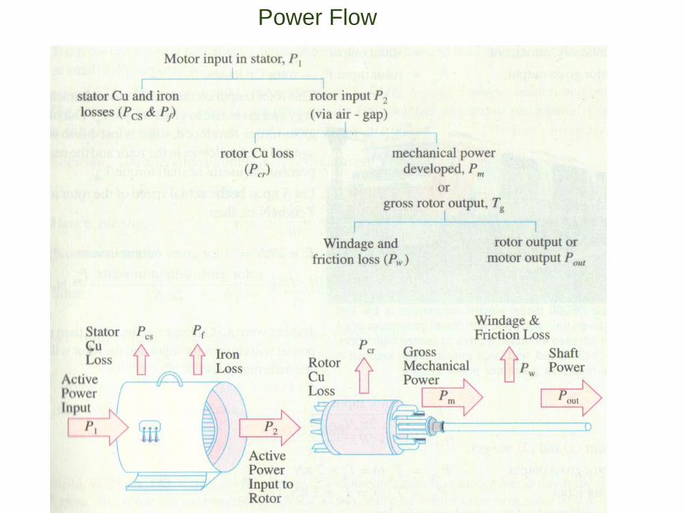
Power Flow
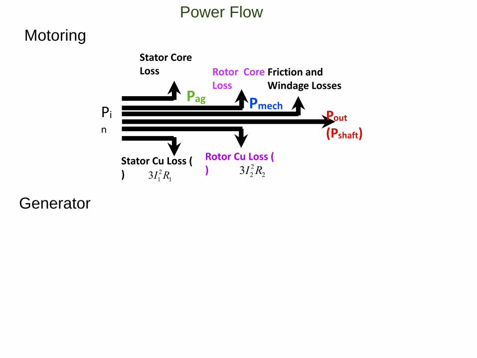
Pi
n
Stator Core Loss
Stator Cu Loss ( )
Pag
Rotor Core Loss
Rotor Cu Loss ( )
3I12R1
3I22R2
Pmech
Friction and Windage Losses
Pout
(Pshaft)
Power Flow
Motoring
Generator
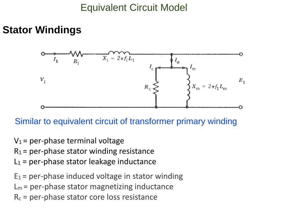
Equivalent Circuit Model
Stator Windings
Similar to equivalent circuit of transformer primary winding
V1 = per-phase terminal voltageR1 = per-phase stator winding resistanceL1 = per-phase stator leakage inductance
E1 = per-phase induced voltage in stator windingLm = per-phase stator magnetizing inductanceRc = per-phase stator core loss resistance
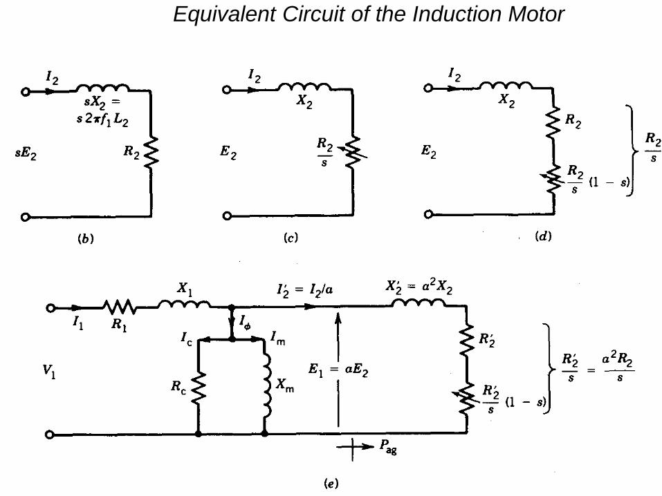
Equivalent Circuit of the Induction Motor
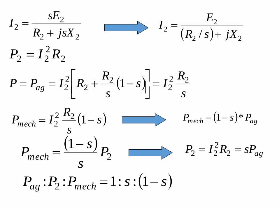
22
22
jsXR
sEI
2222 RIP
22
22
/ jXsR
EI
s
RIs
s
RRIPP ag
222
22
22 1
ss
RIPmech 122
2 agmech PsP *1
2
1P
s
sPmech
agsPRIP 2
222
ssPPP mechag 1::1:: 2
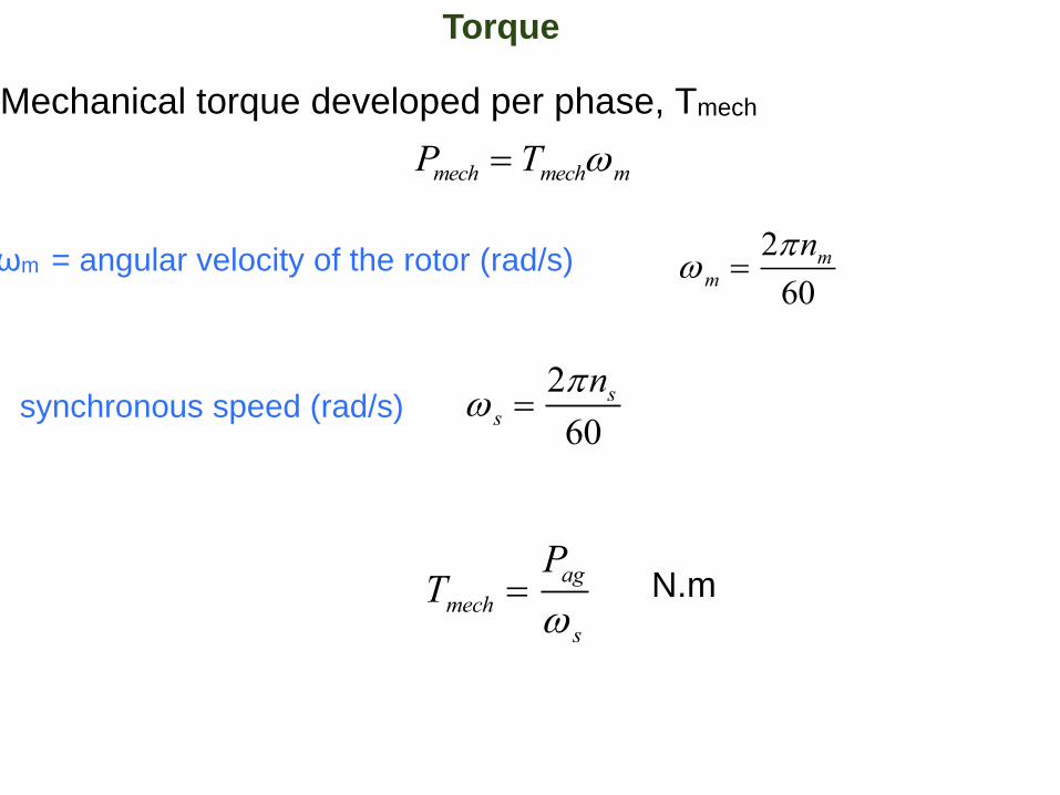
Torque
Mechanical torque developed per phase, Tmech
Pmech Tmechm
ωm = angular velocity of the rotor (rad/s) m 2nm60
s 2ns60
synchronous speed (rad/s)
Tmech Pag
s
N.m
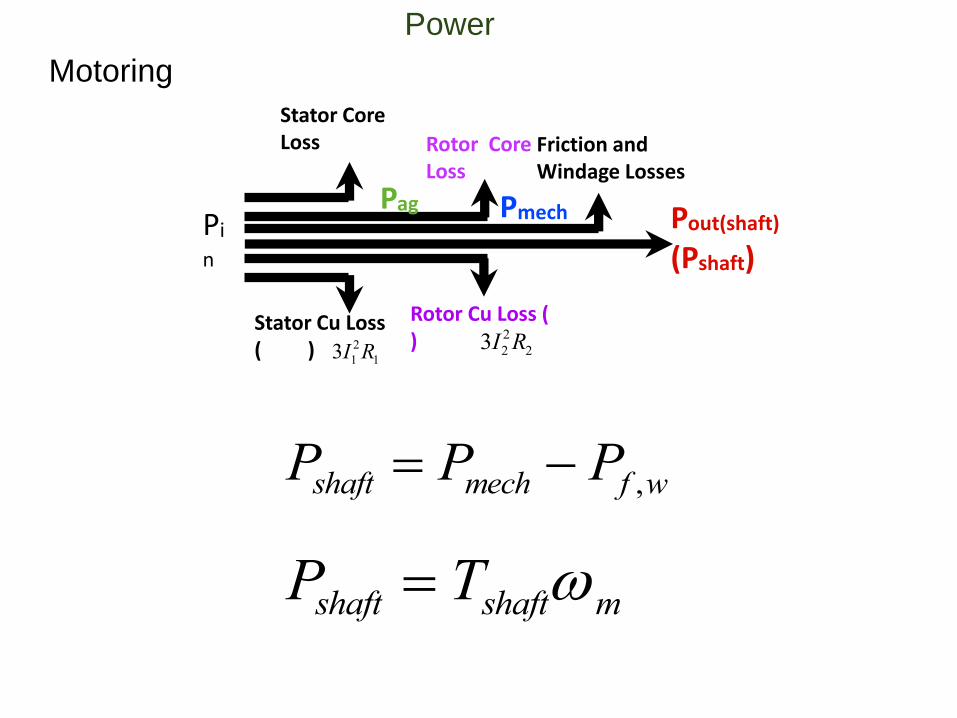
Pi
n
Stator Core Loss
Stator Cu Loss ( )
Pag
Rotor Core Loss
Rotor Cu Loss ( )
3I12R1
3I22R2
Pmech
Friction and Windage Losses
Pout(shaft)
(Pshaft)
Motoring
Power
Pshaft Tshaftm
Pshaft Pmech Pf ,w
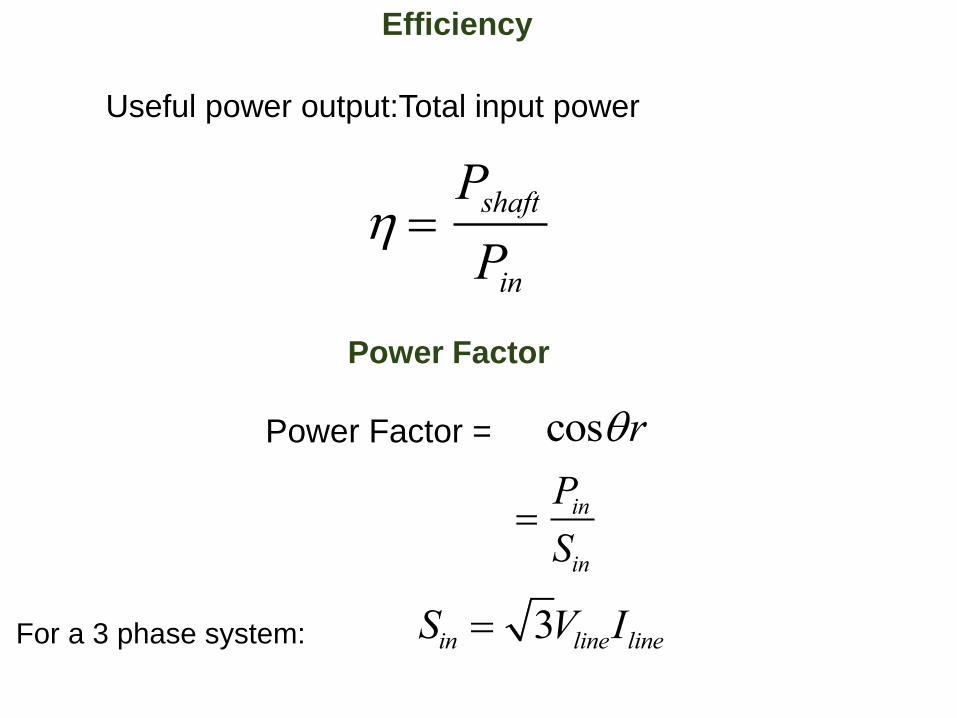
Efficiency
Useful power output:Total input power
Pshaft
Pin
Power Factor
Power Factor = cosr
Pin
Sin
For a 3 phase system: Sin 3VlineIline
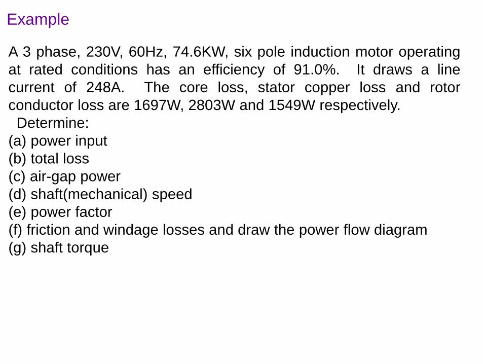
Example
A 3 phase, 230V, 60Hz, 74.6KW, six pole induction motor operating
at rated conditions has an efficiency of 91.0%. It draws a line
current of 248A. The core loss, stator copper loss and rotor
conductor loss are 1697W, 2803W and 1549W respectively.
Determine:
(a) power input
(b) total loss
(c) air-gap power
(d) shaft(mechanical) speed
(e) power factor
(f) friction and windage losses and draw the power flow diagram
(g) shaft torque