Embed Size (px)
Citation preview

lable at ScienceDirect
Journal of Power Sources 329 (2016) 502e509
Contents lists avai
Journal of Power Sources
journal homepage: www.elsevier .com/locate/ jpowsour
Study on the blocking effect of a quantum-dot TiO2 compact layer indye-sensitized solar cells with ionic liquid electrolyte under low-intensity illumination
Peng Zhai a, b, **, Hyeonseok Lee a, Yu-Ting Huang a, Tzu-Chien Wei c, Shien-Ping Feng a, *
a Department of Mechanical Engineering, The University of Hong Kong, Pokfulam Rd., Hong Kongb MOE Key Laboratory of Space Applied Physics and Chemistry, Shaanxi Key Laboratory of Macromolecular Science and Technology, School of Science,Northwestern Polytechnical University, Xi'an, 710072, PR Chinac Department of Chemical Engineering, National Tsing-Hua University, Hsinchu 300, Taiwan
h i g h l i g h t s
* Corresponding author.** Co-corresponding author. MOE Key Laboratory oChemistry, Shaanxi Key Laboratory of MacromolecuSchool of Science, Northwestern Polytechnical Univer
E-mail addresses: [email protected] (P. Zhai)
http://dx.doi.org/10.1016/j.jpowsour.2016.08.1180378-7753/© 2016 Elsevier B.V. All rights reserved.
g r a p h i c a l a b s t r a c t
� Ultrasmall and ultrafine TiO2 quan-tum dots are prepared.
� The performance of DSCs with TiO2quantum-dots compact layer isdeeply investigated.
� The controversy over the blockingeffect of TiO2 compact layer isclarified.
a r t i c l e i n f o
Article history:Received 7 July 2016Received in revised form12 August 2016Accepted 28 August 2016Available online 2 September 2016
Keywords:Quantum-dot TiO2
Compact layerLow-intensity illuminationElectron recombinationDye-sensitized solar cellsIonic liquid electrolyte
a b s t r a c t
In this study, ultrasmall and ultrafine TiO2 quantum dots (QDs) were prepared and used as a high-performance compact layer (CL) in dye-sensitized solar cells (DSCs). We systematically investigatedthe performance of TiO2 CL under both low-intensity light and indoor fluorescent light illumination andfound that the efficiency of DSCs with the insertion of optimal TiO2 QDs-CL was increased up to 18.3%under indoor T5 fluorescent light illumination (7000 lux). We clarified the controversy over the blockingeffect of TiO2 CL for the efficiency increment and confirmed that the TiO2 QDs-CL performed significantlybetter under low-intensity illumination due to the efficient suppression of electron recombination at theFTO/electrolyte interface. We, for the first time, demonstrate this potential for the application of the DSCswith TiO2 QDs-CL in the low-intensity light and indoor fluorescent light illumination.
© 2016 Elsevier B.V. All rights reserved.
f Space Applied Physics andlar Science and Technology,sity, Xi’an, 710072, PR China., [email protected] (S.-P. Feng).
1. Introduction
Due to their lower manufacturing cost and environmentallyfriendly characteristics, dye-sensitized solar cells (DSCs) areregarded as promising next-generation alternatives to conven-tional silicon-based photovoltaic devices. Although a DSC power

P. Zhai et al. / Journal of Power Sources 329 (2016) 502e509 503
conversion efficiency (PCE) of about 11% has been obtained whenusing ruthenium dye in conjunction with an I3�/I� redox couple [1],it still cannot compete with the crystalline silicon solar cells thatdominate the solar cell market, which are superior in their outdoorpower generation because of broad coverage of the solar spectrum[2]. The main obstacle to the PCE increment of DSCs is theirinsufficient light harvesting capability under outdoor illumination,as a significant fraction of the spectrum falls in the red region ofvisible light. Here, ruthenium complex dye has a much weakerphotoexcited response than that in shorter wavelengths. DSCs maytherefore be more suitable for indoor applications illuminated bythe <700 nm wavelength, such as fluorescent, incandescent, ordaylight. DSCs have also been found to exhibit higher power den-sity across indoor conditions relative to amorphous silicon andorganic photovoltaic solar cells [3], but their characteristics underlow-intensity illumination have not been fully examined. Thecharge transfer, recombination, and PCE of DSCs under lower lightconditions are relatively sensitive to the level of iodine content [4],so to improve their performance, understanding DSCs under lowerintensity illumination is necessary.
Electrolyte containing an iodide/triiodide (I�/I3�) redox couple inacetonitrile is commonly used for electrolyte formulation, due to itsappropriate electrode potential and fast charge transport rate.Acetonitrile-based electrolyte does, however, limit device perfor-mance in practice as its long-term stability (high solvent volatility)and safety (solvent flammability) are poor. Ionic liquids (ILs) exhibitelectrochemical stability, nonvolatility, and high conductivity [5e9]and are of great interest as alternatives. However, serious electronrecombination in ILs is caused by I3� ions at the FTO/electrolyte andmeso-TiO2/dye/electrolyte interfaces, as practically ILs require aconcentration of I�/I3� redox couples almost 10 times higher thanthat in acetonitrile-based electrolyte, to facilitate the physical masstransfer [10,11]. Particularly for DSCs under low-intensity illumi-nation, since meso-TiO2 is electronically less-conducting or eveninsulating, the electron recombination occurring at the meso-TiO2/dye/electrolyte interface is thus negligible, but the massive I3� ionslocalized at the FTO/electrolyte interface will still intensify thebackward electron reaction. Many researchers have applied acompact and thin layer of TiO2 on the transparent conducting glasssubstrate to reduce the backward reaction and improve the open-circuit voltage (VOC) and PCE. Various methods have been used,such as atomic layer deposition (ALD) [12], chemical vapor depo-sition (CVD) [13], sputtering [14,15], eletroplating [16], dip-coating[17,18], spin-coating [19,20], and spray hydrolysis [21]. The blockingeffect produced by the TiO2 compact layer (CL) is controversial, asTiO2 CL deposition can affect the optical and adhesion propertiesand it appears to be difficult to isolate the CL's effect from the PCEenhancement [22].
To the best of our knowledge, no studies into the properties ofTiO2 quantum dots (QDs) CL in ILs-based DSCs under low-intensityillumination have been conducted. In this study, ultrasmall andultrafine TiO2 QDs were prepared and deposited on FTO to formTiO2 CL. To clarify the blocking effect, an in-depth investigation ofthe TiO2 CL under low-intensity light and commercial T5 fluores-cent light conditions was carried out. The TiO2 QDs-CL was found toperform better under low-intensity illumination, demonstrated bya slow VOC decay rate with decreasing light illumination.
2. Experimental section
2.1. Synthesis of ultrasmall TiO2 QDs
1 mL of TiCl4 was slowly introduced into a glass vial containing5 mL of ethanol, producing a transparent yellow solution. The so-lution was slowly added under vigorous stirring to 15 mL of benzyl
alcohol and heated at 80 �C under continuous stirring throughoutthe synthesis for a series of reaction times, from 2 to 8 h. Stable TiO2sols were then selected for subsequent spin-coating on FTO glass.
2.2. Deposition of a TiO2 compact layer on FTO glass
FTO glass (10 U/,, 3.1 mm thick, Nippon Sheet Glass) wasimmersed in 2% PK-LCG545 (Parker Corp.) at 70 �C for 30 min andthe surface was cleaned by sonication, followed by a deionizedwater rinse. The clean FTO glass was made superhydrophilic byputting it into UV ozone for 30 min, due to the hydrophobicity ofbenzyl alcohol. Two TiO2 CLs (dispersion of TiO2 QDs in benzylalcohol) were deposited on the FTO for 2 h and 4 h, respectively, byspin-coating (5000 rpm, 30 s), then kept in a dry box until theorganic solvent evaporated spontaneously. The film was then sub-jected to thermal annealing in a furnace (450 �C, 30 min).
2.3. DSCs cell assembly
The nano-TiO2 paste (particle size 20 nm, product, Eternal) wasthen repeatedly screen-printed onto TiO2 CL FTO glass, until thefilm thickness was 6 mm. A 2 mm light scattering film (PST400, CCIC)was screen-printed onto the nano-TiO2 film. The double layeredfilm was then sintered at 450 �C for 30 min in a furnace. For thecontrol sample, TiO2 CL on FTO made by TiCl4 treatment (hereaftercalled TiCl4-CL), 40 mM of TiCl4 solution was applied in pre-treatment. Dye was impregnated by immersing the TiO2 photo-anode in a 0.3 mM N719 solution (in ethanol/DMSO ~ 9:1) at roomtemperature for 10 h. The dye-adsorbed TiO2 photoanode and thePt counter electrode were stacked face-to-face and sealed with a30 mm-thick thermal-plastic Surlyn spacer (SX1170-25, Solaronix).The electrolyte consisted of 0.2 M I2, 0.1 M GuSCN (Guanidinethiocyanate), and 0.5 M NBB (N-Butylbenzimidazole) in binaryPMII þ EMITCB (65:35 v/v) ionic liquids (PMII ¼ 1-methyl-3-propylimidazolium iodide, EMITCB ¼ 1-ethyl-3-methyl-imidazolium tetracyanoborate). The active area of the dye-coatedTiO2 film was 0.16 cm2. A black mask was used in the subsequentphotovoltaic studies.
2.4. Electrochemical and DSC characterization
Electrochemical impedance spectroscopy (EIS) wasmeasured byscanning the DSC cell with different applied bias with a potentio-stat from 100 kHz to 0.01 Hz with an amplitude of 5 mV in open-circuit conditions (1286 Solartron and 1255 Solartron, UK). Thecurrent-voltage (J-V) curve of the DSC cell was measured with acomputer-controlled digital source meter (Keithley 2400) underexposure of a standard solar simulator (PEC-L01, Peccell), of 1 sunillumination (AM 1.5G, 100 mW$cm�2). The lower intensity illu-minationwas measured with ND filters with transmittances of 55%,10%, and 5.5%. The J-V curve of the DSCs under the different lumi-nance of indoor fluorescent light (T5 commercial type) conditionswas measured in accordance with a published paper [23].
3. Results and discussions
3.1. TiO2 QDs/CL synthesis and structural characterization
The nonaqueous synthesis of metal oxide nanoparticles frommetal halides and alkoxides with organics have been studied fordecades. The underlying mechanism relates to so-called alkylhalide elimination, or an ether elimination [24e26].
Fig. 1a clearly shows the continuous change of TiO2 sols overtime. It turns transparent yellow after a 2 h reaction and then be-comes slightly turbid after 4 h reaction. The competition between

Fig. 1. (a) Photograph of the continuous change of TiO2 sol over time, clearly revealing that the TiO2 QDs are energetically formed and tend to be agglomerated until the occurrenceof sedimentation; (b) TEM image of the TiO2 nanoclusters (4h sol) composed of numerous TiO2 QDs; (c) corresponding SAED pattern of (b).
P. Zhai et al. / Journal of Power Sources 329 (2016) 502e509504
alkyl halide elimination and ether elimination results in more TiO2QDs being energetically formed [27]. After 5 h reaction, TiO2 QDstend to become agglomerated until the occurrence of sedimenta-tion. Fig. 1b displays the TEM image of TiO2 nanocluster, which iscomposed of numerous ultrasmall TiO2 QDs. The selected-areaelectron diffraction (SAED) pattern shown in Fig. 1c suggests thatthe TiO2 QDs have well-defined diffraction ring for anatase TiO2.Dynamic light scattering (DLS) is used to gain further insight intothe particle size distribution. The calculated volume-weighted sizedistributions presented in Fig. S1 for these stable sols show anaverage particle size of about 12.5 nm after a 2 h reaction, 19.9 nmafter 3 h reaction, and 23.9 nm after 4 h reaction, indicating thatagglomeration commences after a 2 h reaction and results from alack of stabilization of the TiO2 QDs in the hydrophobic and viscousbenzyl alcohol medium. However, the particle size resolved by DLSevidently exceeds the single particle size of ~2 nm observed in theHRTEM image (Fig. 2a), presenting that the large TiO2 nanocluster isprone to form in the presence of substantial amounts of agglom-erates. The random crystal structure is further confirmed byHRTEMimages, together with the schematic illustrations of crystal orien-tation of TiO2 QDs. These images demonstrate three characteristicanatase TiO2 crystal structures. Fig. 2b shows the crystal orientationof (101) and (004) faces with an interfacial angle of 68.3�. Theanalysis of the fast Fourier transformation (FFT) indicates that theisolated TiO2 QDs is oriented along the [010] direction with respectto the electron beam. Fig. 2c displays a square shape indicative of a{001} facet, and its FFT pattern clearly reveals the atomic planes of(200) or (020) crystal faces with an interfacial angle of 90�. Fig. 2dpresents the (101) and (011) faces with an interfacial angle of 82.4�,its FFT pattern further indexes [11�ı] the zone axis and also high-lights the (011) and (101) faces [28].
Fig. 3aec compares three TiO2 CLs with different coverage onthe FTO substrate prepared by spin-coating. TiO2 QDs-CL made by4 h sol (hereafter called 4h-CL) can be seen to have a better
coverage than the 2h/3h-CLs, and the surface morphology of 4h-CLis smooth and compact, whereas 2h/3h-CLs display unambiguouspin-hole defects. The cross-sectional image of 4h-CL is displayed inthe inset of Fig. 3c, which is composed of dense-packed TiO2 QDswith a film thickness of around 80 nm. The SEM images ofdiscontinuous TiCl4-CL prepared by TiCl4 pre-treatment are shownin Fig. S2, in which the isolated TiO2 nanoparticles sitting on theFTO surface can be clearly seen.
Atomic force microscopy (AFM) images in Fig. 4 indicate that theroot-mean-square roughness (Rrms) of the bare FTO surface was ashigh as 41.9 nm, compared to 34.6 nm for 2h-CL, and 28.4 nm for4h-CL.
3.2. Electrochemical characterization and DSC performance underlower intensity conditions
The photovoltaic performance of the DSCs with TiO2-CLs in thephotoanodes is shown in Fig. 5a, the extracted cell performanceparameters of 4h-CL are tabularized in Table 1, and the other per-formance levels of DSCs are listed in Table S1.
Their J-V curves are shown in Fig. S3. The ILs-based DSCs withTiO2 CL under different sunlight (1, 0.55, 0.1, and 0.055 sun) andindoor T5 fluorescent light (7000e350 lux) conditions exhibit su-perior photovoltaic performance compared to their standardcounterparts. The standard cell delivers a short circuit current (JSC)of 12 mAcm�2, a VOC of 0.68 V, and a fill factor (FF) of 0.73, resultingin a PCE of 5.94%. The cell with 4h-CL gives the highest JSC of13.90 mAcm�2, coupled with the largest VOC of 0.72 V among allsamples, and an FF of 0.74, so a PCE of 7.40% is achieved. The per-formance of 2h-CL and TiCl4-CL DSCs shows improved JSC, VOC, FF,and PCE but they cannot compete with the 4h-CL due to thepin-hole defects. The PCE of each DSC under low-intensity illumi-nation demonstrates better performance than that in full suncondition. This improvement is associated with the two positive

Fig. 2. HRTEM images of (a) random TiO2 QDs dispersed in benzyl alcohol (4 h sol); (b)e(d) typical anatase TiO2 nanostructures and their corresponding FFTs.
Fig. 3. FESEM images of (a) magnified and low 2h-CL on FTO substrate. The dotted circle marks the pin-hole defects resulting from the poor coverage of TiO2 QDs; (b) magnified andlow 3h-CL on FTO substrate; and (c) magnified and low 4h-CL on FTO substrate. The inset displays its cross-sectional image, with a thickness of 80 nm.
P. Zhai et al. / Journal of Power Sources 329 (2016) 502e509 505
effects of less electron recombination, which improves VOC, and lessdiffusion overpotential, which improves FF [4]. In general, the peakoutput for DSCs characterization under outdoor or sunlight con-ditions is reported at standard test conditions with intensities of
1000 W/m2. However, indoor lighting conditions are different. Inphotometry, illuminance is the total luminous flux incident on asurface, per unit area. Lux is a typical unit for measuring indoorlighting. Based on the empirical relationship between lux and W/

Fig. 4. AFM images of (a) bare FTO substrate; (b) TiCl4-CL on FTO; (c) 2h-CL on FTO; and (d) 4h-CL on FTO. The scanned area was 10 � 10 mm.
P. Zhai et al. / Journal of Power Sources 329 (2016) 502e509506
m2, the average indoor lighting is approximately 1e2 W/m2, whichis 500 times lower than outdoor conditions [3]. Here, the PCE ofDSCs under indoor T5 fluorescent light illumination dramaticallyincreases by up to 18.3%, particularly for the 4h-CL device under7000 lux, which is attributed to the stronger spectral response ofruthenium dye toward to T5 light spectral distribution. As Fig. S4illustrated, the T5 maximum peak of 546 nm is close to themaximum absorbance of the ruthenium dye at 530 nm. As the T5light illuminance weakens, the PCE can be seen to decrease, as asignificant proportion of the incident light is absorbed when theconcentration of I3� in the ILs-electrolyte is high. The monotonicdecrease in VOC under lower light conditions for each DSC device(shown in Fig. 5b) can be explained by the Fermi level of TiO2decreasing due to fewer photoelectrons being generated andinjected. As discussed, in low-intensity light conditions ILs-electrolyte diffusion depends on electron-hopping along contin-uous I�/I3� chains as meso-TiO2 is electronically less-conducting oreven insulating [10]. Substantial I3� ions localized at the FTO/elec-trolyte interface tend to intensify the electron backward reaction,causing VOC loss. The slow VOC decay rate for the 4h-CL device, suchas the 16.4% VOC decay at 350 lux relative to 7000 lux, demonstratesits superior “blocking” function of a standard cell without TiO2 CLcoating (20.4% VOC decay) and the TiCl4-CL cell (22.4% VOC decay).An optimal coverage of TiO2 CL on FTO thus effectively suppressesthe electron backward transport from the FTO to the I3� ions, andhence DSCs with 4h-CL possess higher VOC in any lower intensitylight conditions. The corresponding output power densities of theDSCs are listed in the last column of Tables 1 and S1 for the T5fluorescent light source under different illuminances. The 4h-CLdevice performs best at all illuminance levels, with an output po-wer density 9.4% and 14.0% greater than the TiCl4-CL and standard
cells, respectively, at 7000 lux illuminance. Several factors may,however, be involved in the observed increase in JSC for the 4h-CLdevice. First, the higher transparency for the FTO substrate is inprinciple extremely important at lower intensity illumination, asthe amount of incident light is valuably limited. The transmittancespectra for the TiCl4-CL/FTO, 4h-CL/FTO, 2h-CL/FTO, and the bareFTO substrate are shown in Fig. 5c. The 4h-CL/FTO displays highertransparency (T550 ~76.1%) than the TiCl4-CL/FTO (T550 ~70.0%) andbare FTO (T550 ~70.2%), due to improved uniformity of the filmsurface resulting from the formation of the TiO2 CL on FTO by TiO2QDs. On a rough surface, shorter wavelength light is relatively morescattered than that of a longer wavelength so the smooth 4h-CLsurface with Rrms ~28.4 nm benefits the incident light harvesting.The improved transparency (8.4% enhancement compared to thatof bare FTO) will then partially contribute to its JSC. The mechanicaladhesion between meso-TiO2/FTO also increases due to the inser-tion of smooth TiO2 CL. More effective electron pathways aregenerated via this CL, facilitating electron transfer to the externalcircuit and resulting in JSC improvement [18]. By comparison, theDSC with only 4h-CL (without the meso-TiO2 film) in the photo-anode shows a poor JSC of 0.29 mAcm�2, a VOC of 0.58 V, an FF of0.60, and a PCE of 0.10% under 1 sun illumination. The JSC generatedfrom TiO2 CL is consequently insignificant in PCE enhancement.Fig. 5d presents the incident photon-to-current conversion effi-ciency spectra (IPCE) for the DSCs with and without TiO2 CL. Theintroduction of the TiO2 CL appreciably increased the quantumefficiency over the whole spectral range of incident light(300e800 nm).
The effects of the TiO2 CL on the resistance of the interfaces inthe DSCs can be further investigated through the EIS study. Themeasurements are analyzed using the transmission line (TL) model
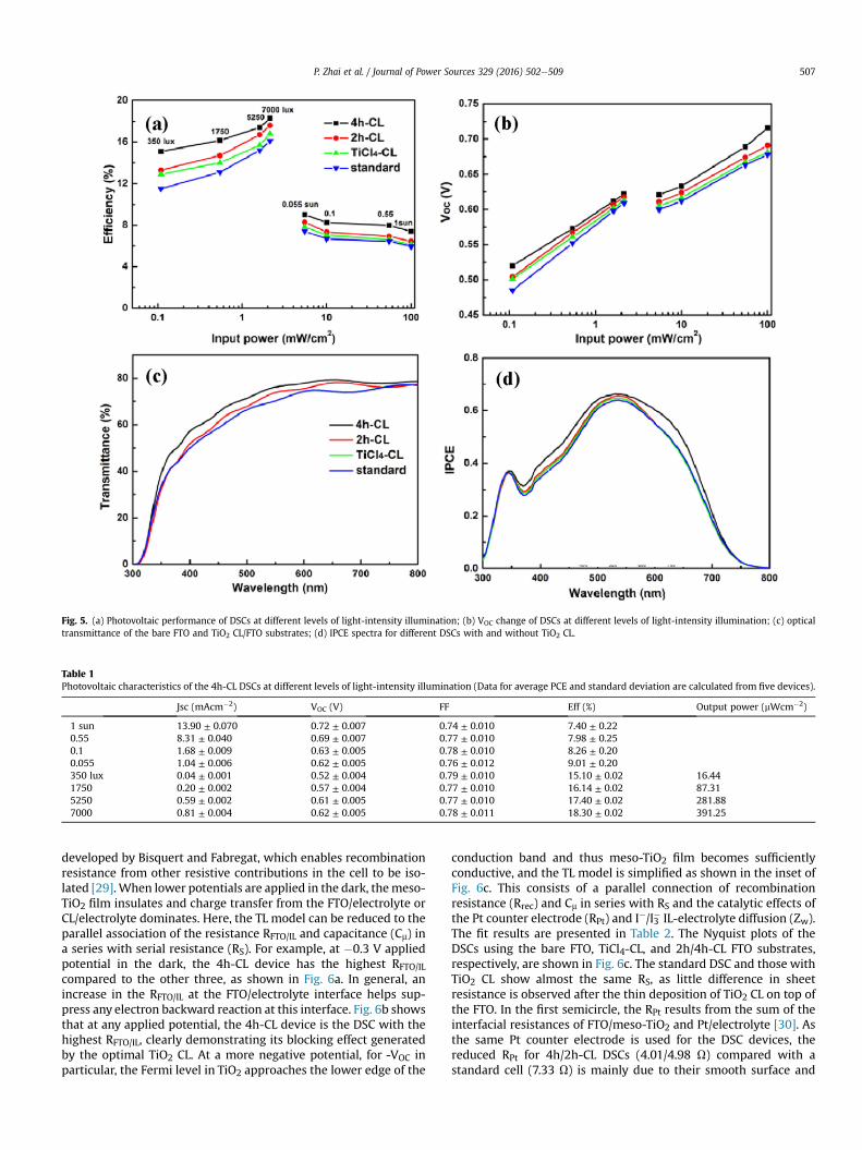
Fig. 5. (a) Photovoltaic performance of DSCs at different levels of light-intensity illumination; (b) VOC change of DSCs at different levels of light-intensity illumination; (c) opticaltransmittance of the bare FTO and TiO2 CL/FTO substrates; (d) IPCE spectra for different DSCs with and without TiO2 CL.
Table 1Photovoltaic characteristics of the 4h-CL DSCs at different levels of light-intensity illumination (Data for average PCE and standard deviation are calculated from five devices).
Jsc (mAcm�2) VOC (V) FF Eff (%) Output power (mWcm�2)
1 sun 13.90 ± 0.070 0.72 ± 0.007 0.74 ± 0.010 7.40 ± 0.220.55 8.31 ± 0.040 0.69 ± 0.007 0.77 ± 0.010 7.98 ± 0.250.1 1.68 ± 0.009 0.63 ± 0.005 0.78 ± 0.010 8.26 ± 0.200.055 1.04 ± 0.006 0.62 ± 0.005 0.76 ± 0.012 9.01 ± 0.20350 lux 0.04 ± 0.001 0.52 ± 0.004 0.79 ± 0.010 15.10 ± 0.02 16.441750 0.20 ± 0.002 0.57 ± 0.004 0.77 ± 0.010 16.14 ± 0.02 87.315250 0.59 ± 0.002 0.61 ± 0.005 0.77 ± 0.010 17.40 ± 0.02 281.887000 0.81 ± 0.004 0.62 ± 0.005 0.78 ± 0.011 18.30 ± 0.02 391.25
P. Zhai et al. / Journal of Power Sources 329 (2016) 502e509 507
developed by Bisquert and Fabregat, which enables recombinationresistance from other resistive contributions in the cell to be iso-lated [29].When lower potentials are applied in the dark, themeso-TiO2 film insulates and charge transfer from the FTO/electrolyte orCL/electrolyte dominates. Here, the TL model can be reduced to theparallel association of the resistance RFTO/IL and capacitance (Cm) ina series with serial resistance (RS). For example, at �0.3 V appliedpotential in the dark, the 4h-CL device has the highest RFTO/IL
compared to the other three, as shown in Fig. 6a. In general, anincrease in the RFTO/IL at the FTO/electrolyte interface helps sup-press any electron backward reaction at this interface. Fig. 6b showsthat at any applied potential, the 4h-CL device is the DSC with thehighest RFTO/IL, clearly demonstrating its blocking effect generatedby the optimal TiO2 CL. At a more negative potential, for -VOC inparticular, the Fermi level in TiO2 approaches the lower edge of the
conduction band and thus meso-TiO2 film becomes sufficientlyconductive, and the TL model is simplified as shown in the inset ofFig. 6c. This consists of a parallel connection of recombinationresistance (Rrec) and Cm in series with RS and the catalytic effects ofthe Pt counter electrode (RPt) and I�/I3� IL-electrolyte diffusion (Zw).The fit results are presented in Table 2. The Nyquist plots of theDSCs using the bare FTO, TiCl4-CL, and 2h/4h-CL FTO substrates,respectively, are shown in Fig. 6c. The standard DSC and those withTiO2 CL show almost the same RS, as little difference in sheetresistance is observed after the thin deposition of TiO2 CL on top ofthe FTO. In the first semicircle, the RPt results from the sum of theinterfacial resistances of FTO/meso-TiO2 and Pt/electrolyte [30]. Asthe same Pt counter electrode is used for the DSC devices, thereduced RPt for 4h/2h-CL DSCs (4.01/4.98 U) compared with astandard cell (7.33 U) is mainly due to their smooth surface and

Fig. 6. (a) Nyquist plot for different DSCs at �0.3 V in the dark. The inset shows its corresponding equivalent circuit diagram; (b) EIS results of DSCs at a series of lower appliedpotentials; (c) Nyquist plot for different DSCs at their respective -VOC in the dark. The inset shows its corresponding equivalent circuit diagram; (d) Bode plot.
Table 2Parameters determined by fitting the impedance spectra of four kinds of DSCsdevices.
RS (U) RPt (U) Rrec (U) Rw (U) u (Hz)
4h-CL 21.33 4.01 61.05 24.35 15.852h-CL 20.97 4.98 77.28 26.44 19.95TiCl4-CL 21.25 7.64 92.14 34.69 19.95Standard 21.35 7.33 89.11 34.81 19.95
P. Zhai et al. / Journal of Power Sources 329 (2016) 502e509508
better mechanical adhesion, which to an extent contribute to theimproved electrical contact. In our observation, the Rrec at themeso-TiO2/electroyte interface after the insertion of thin TiO2 CL(4h-CL ~61.05 U and 2h-CL ~77.28 U) is lower than that TiCl4-CL(92.14 U) and standard (89.11 U) DSCs. Decrease in Rrec was, in aprevious report, attributed to the improvedmechanical adhesion ofthe nanocrystalline meso-TiO2 film on the substrate. The maximumfrequency in the second semicircle (shown in Fig. 6d) relates to theelectron lifetime as the inverse of this frequency is proportional toVOC, suggesting that the 4h-CL device (15.85 Hz) is likely to possessa longer electron lifetime than other DSCs (19.95 Hz). Here, we, forthe first time, find that the Zw reduction of 4h/2h-CL DSCs (24.35/26.44 U) is a strong indication of a suppressed electron backwardreaction, as the overwhelming I3� ions are effectively blocked byTiO2 CL at the FTO/electrolyte interface. This tends to expand theion concentration gradient within the whole cell, leading toimproved mass transfer toward the Pt counter electrode. EIS con-firms that the thin TiO2 CL deposition eventually reduces the total
internal resistance of the cell (RS, RPt, Rrec, and Zw), which is alsoassociated with the improved FF. Recalling the controversy over theblocking effect produced by the TiO2 CL, we confirm that opticalgain and better mechanical adhesion partly contribute to the in-crease in JSC and FF as previously reported. The slow VOC decay inlower intensity light conditions, the longer the electron lifetime,and the rapid ILs-electrolyte diffusivity caused by TiO2 CL providesevidence that the blocking effect definitely benefits the VOC andthus PCE.
4. Conclusion
A new kind of compact layer was prepared by spin-coatingultrafine and ultrasmall TiO2 QDs on FTO. We systematicallyinvestigated the photovoltaic performance of DSCs with TiO2 CL inlow-intensity illumination and clarified the controversy over theblocking effect of TiO2 CL for the PCE increment. The more trans-parent surface and improved mechanical adhesion caused by TiO2CL in part contribute to the increase in JSC and FF, but we confirmedthat the slow VOC decay in the lower-intensity light conditions,longer electron lifetime, and fast ILs-electrolyte diffusivity from thedeposition of TiO2 CL further enhance the VOC and thus the PCE dueto its effective blocking function.
Acknowledgments
This work was supported by the General Research Fund under

P. Zhai et al. / Journal of Power Sources 329 (2016) 502e509 509
Award Number HKU 712213E and 17202314 (S.-P.F.), and theCollaborative Research Fund under Award Number C7045-14E fromResearch Grants Council of Hong Kong Special Administrative Re-gion, China. This work was also partially supported by StrategicResearch Theme on Clean Energy from the University of Hong Kong.
Appendix A. Supplementary data
Supplementary data related to this article can be found at http://dx.doi.org/10.1016/j.jpowsour.2016.08.118.
References
[1] C.-Y. Chen, M. Wang, J.-Y. Li, N. Pootrakulchote, L. Alibabaei, C.-h. Ngoc-le, J.-D. Decoppet, J.-H. Tsai, C. Gr€atzel, C.-G. Wu, ACS Nano 3 (2009) 3103e3109.
[2] S. Ito, H. Matsui, K.-i. Okada, S.-i. Kusano, T. Kitamura, Y. Wada, S. Yanagida,Sol. Energy Mater. Sol. Cells 82 (2004) 421e429.
[3] N. Sridhar, D. Freeman, in: 26th European Photovoltaic Solar Energy Confer-ence and Exhibition, 2011.
[4] J.-L. Lan, T.-C. Wei, S.-P. Feng, C.-C. Wan, G. Cao, J. Phys. Chem. C 116 (2012)25727e25733.
[5] D. Kuang, C. Klein, Z. Zhang, S. Ito, J.E. Moser, S. Zakeeruddin, M. Gr€atzel, Small3 (2007) 2094e2102.
[6] S.M. Zakeeruddin, M. Graetzel, Adv. Funct. Mater. 19 (2009) 2187e2202.[7] P. Wang, S.M. Zakeeruddin, R. Humphry-Baker, M. Gr€atzel, Chem. Mater. 16
(2004) 2694e2696.[8] R. Kawano, M. Watanabe, Chem. Commun. (2003) 330e331.[9] M. Berginc, M. Ho�cevar, U.O. Kra�sovec, A. Hinsch, R. Sastrawan, M. Topi�c, Thin
Solid Films 516 (2008) 4645e4650.
[10] J. Xia, N. Masaki, K. Jiang, S. Yanagida, Chem. Commun. (2007) 138e140.[11] J. Xia, N. Masaki, K. Jiang, S. Yanagida, J. Phys. Chem. C 111 (2007) 8092e8097.[12] D.H. Kim, M. Woodroof, K. Lee, G.N. Parsons, ChemSusChem. 6 (2013)
1014e1020.[13] M. Thelakkat, C. Schmitz, H.W. Schmidt, Adv. Mater. 14 (2002) 577e581.[14] C.S. Kovash, J.D. Hoefelmeyer, B.A. Logue, Electrochim. Acta 67 (2012)
18e23.[15] M. Hossain, S. Biswas, T. Takahashi, Thin Solid Films 517 (2008) 1294e1300.[16] M.-S. Wu, C.-H. Tsai, T.-C. Wei, J. Electrochem. Soc. 159 (2011) B80eB85.[17] H. Choi, C. Nahm, J. Kim, J. Moon, S. Nam, D.-R. Jung, B. Park, Curr. Appl. Phys.
12 (2012) 737e741.[18] H. Yu, S. Zhang, H. Zhao, G. Will, P. Liu, Electrochim. Acta 54 (2009)
1319e1324.[19] B. Yoo, K.-J. Kim, S.-Y. Bang, M.J. Ko, K. Kim, N.-G. Park, J. Electroanal. Chem.
638 (2010) 161e166.[20] Y.J. Kim, Y.H. Lee, M.H. Lee, H.J. Kim, J.H. Pan, G.I. Lim, Y.S. Choi, K. Kim, N.-
G. Park, C. Lee, Langmuir 24 (2008) 13225e13230.[21] B. Peng, G. Jungmann, C. J€ager, D. Haarer, H.-W. Schmidt, M. Thelakkat, Coord.
Chem. Rev. 248 (2004) 1479e1489.[22] B. Yoo, K. Kim, D.-K. Lee, M.J. Ko, H. Lee, Y.H. Kim, W.M. Kim, N.-G. Park, J. Mat.
Chem. 20 (2010) 4392e4398.[23] Y. Li, N.J. Grabham, S.P. Beeby, M. Tudor, Sol. Energy 111 (2015) 21e29.[24] M. Niederberger, M.H. Bartl, G.D. Stucky, J. Am. Chem. Soc. 124 (2002)
13642e13643.[25] I. Bilecka, M. Niederberger, Electrochim. Acta 55 (2010) 7717e7725.[26] M. Niederberger, M.H. Bartl, G.D. Stucky, Chem. Mater 14 (2002) 4364e4370.[27] G. Garnweitner, C. Grote, Phys. Chem. Chem. Phys. 11 (2009) 3767e3774.[28] J. Zhu, S. Wang, Z. Bian, S. Xie, C. Cai, J. Wang, H. Yang, H. Li, Cryst. Eng. Comm.
12 (2010) 2219e2224.[29] J. Bisquert, F. Fabregat-Santiago, I.n. Mora-Ser�o, G. Garcia-Belmonte,
S. Gim�enez, J. Phys. Chem. C 113 (2009) 17278e17290.[30] L. Que, Z. Lan, W. Wu, J. Wu, J. Lin, M. Huang, J. Power Sources 268 (2014)
670e676.


![Electrochemical study of TiO2 in aqueous AlCl3 electrolyte ...bmcenergy.biomedcentral.com › track › pdf › 10.1186 › s42500-019-0010-9logues [14, 15], the number of negative](https://img.pdfslide.us/doc/110x75/60e4f6c3e05fab73085a264c/electrochemical-study-of-tio2-in-aqueous-alcl3-electrolyte-a-track-a-pdf.jpg)