Embed Size (px)
Citation preview

Journal of Industrial and Engineering Chemistry 18 (2012) 1551–1559
Review
Carbon nanotube-based membranes: Fabrication and application to desalination
Chang Hoon Ahn a, Youngbin Baek b, Changha Lee c, Sang Ouk Kim d, Suhan Kim e, Sangho Lee f,Seung-Hyun Kim g, Sang Seek Bae h, Jaebeom Park h, Jeyong Yoon b,*a Water and Environment Team, Civil Engineering Center, Samsung C&T Corporation, Seoul 137-956, Republic of Koreab World Class University (WCU) Program of Chemical Convergence for Energy & Environment (C2E2), School of Chemical and Biological Engineering, College of Engineering,
Institute of Chemical Process, Seoul National University (SNU), Seoul 151-742, Republic of Koreac School of Urban and Environmental Engineering, Ulsan National Institute of Science and Technology (UNIST), Ulsan 698-805, Republic of Koread Department of Materials Science and Engineering, KAIST, Daejeon 305-701, Republic of Koreae Department of Civil Engineering, Pukyung National University, Busan 609-735, Republic of Koreaf School of Civil and Environmental Engineering, Kookmin University, Seoul 136-702, Republic of Koreag Department of Civil Engineering, Kyungnam University, Changwon 631-701, Republic of Koreah Department of Water Supply Technology, Korea Water Resources Corporation (K-water), Daejeon 306-711, Republic of Korea
Contents
1. Introduction . . . . . . . . . . . . . . . . . . . . . . . . . . . . . . . . . . . . . . . . . . . . . . . . . . . . . . . . . . . . . . . . . . . . . . . . . . . . . . . . . . . . . . . . . . . . . . . . . . . . 1552
2. Basic CNT information . . . . . . . . . . . . . . . . . . . . . . . . . . . . . . . . . . . . . . . . . . . . . . . . . . . . . . . . . . . . . . . . . . . . . . . . . . . . . . . . . . . . . . . . . . . . 1552
3. Nanofluidics of CNT membranes . . . . . . . . . . . . . . . . . . . . . . . . . . . . . . . . . . . . . . . . . . . . . . . . . . . . . . . . . . . . . . . . . . . . . . . . . . . . . . . . . . . . 1552
4. Fabrication of CNT membranes . . . . . . . . . . . . . . . . . . . . . . . . . . . . . . . . . . . . . . . . . . . . . . . . . . . . . . . . . . . . . . . . . . . . . . . . . . . . . . . . . . . . . 1553
4.1. Types of CNT membranes. . . . . . . . . . . . . . . . . . . . . . . . . . . . . . . . . . . . . . . . . . . . . . . . . . . . . . . . . . . . . . . . . . . . . . . . . . . . . . . . . . . . 1553
4.2. Vertically aligned CNT membranes . . . . . . . . . . . . . . . . . . . . . . . . . . . . . . . . . . . . . . . . . . . . . . . . . . . . . . . . . . . . . . . . . . . . . . . . . . . . 1554
4.3. Mixed (composite) CNT membranes . . . . . . . . . . . . . . . . . . . . . . . . . . . . . . . . . . . . . . . . . . . . . . . . . . . . . . . . . . . . . . . . . . . . . . . . . . . 1554
5. Further considerations of CNT membranes . . . . . . . . . . . . . . . . . . . . . . . . . . . . . . . . . . . . . . . . . . . . . . . . . . . . . . . . . . . . . . . . . . . . . . . . . . . 1554
5.1. Key parameters of CNT membrane performance. . . . . . . . . . . . . . . . . . . . . . . . . . . . . . . . . . . . . . . . . . . . . . . . . . . . . . . . . . . . . . . . . . 1554
5.2. Production of high quality CNTs . . . . . . . . . . . . . . . . . . . . . . . . . . . . . . . . . . . . . . . . . . . . . . . . . . . . . . . . . . . . . . . . . . . . . . . . . . . . . . 1554
5.3. Manufacturing high-performance CNT membranes . . . . . . . . . . . . . . . . . . . . . . . . . . . . . . . . . . . . . . . . . . . . . . . . . . . . . . . . . . . . . . . 1554
5.3.1. CNT density . . . . . . . . . . . . . . . . . . . . . . . . . . . . . . . . . . . . . . . . . . . . . . . . . . . . . . . . . . . . . . . . . . . . . . . . . . . . . . . . . . . . . . . 1555
5.3.2. Aggregation of nanotubes . . . . . . . . . . . . . . . . . . . . . . . . . . . . . . . . . . . . . . . . . . . . . . . . . . . . . . . . . . . . . . . . . . . . . . . . . . . . 1555
5.3.3. Thickness of the CNT layer . . . . . . . . . . . . . . . . . . . . . . . . . . . . . . . . . . . . . . . . . . . . . . . . . . . . . . . . . . . . . . . . . . . . . . . . . . . 1556
5.3.4. Etching process . . . . . . . . . . . . . . . . . . . . . . . . . . . . . . . . . . . . . . . . . . . . . . . . . . . . . . . . . . . . . . . . . . . . . . . . . . . . . . . . . . . . 1556
5.3.5. Filler material . . . . . . . . . . . . . . . . . . . . . . . . . . . . . . . . . . . . . . . . . . . . . . . . . . . . . . . . . . . . . . . . . . . . . . . . . . . . . . . . . . . . . 1556
5.4. Functionalization of CNT tips . . . . . . . . . . . . . . . . . . . . . . . . . . . . . . . . . . . . . . . . . . . . . . . . . . . . . . . . . . . . . . . . . . . . . . . . . . . . . . . . . 1556
6. Desalination potential of CNT membranes . . . . . . . . . . . . . . . . . . . . . . . . . . . . . . . . . . . . . . . . . . . . . . . . . . . . . . . . . . . . . . . . . . . . . . . . . . . . 1557
6.1. Major factors determining desalination potential . . . . . . . . . . . . . . . . . . . . . . . . . . . . . . . . . . . . . . . . . . . . . . . . . . . . . . . . . . . . . . . . . 1557
6.2. Projecting performances of CNT membranes. . . . . . . . . . . . . . . . . . . . . . . . . . . . . . . . . . . . . . . . . . . . . . . . . . . . . . . . . . . . . . . . . . . . . 1557
6.3. Practicable targets for CNT membranes. . . . . . . . . . . . . . . . . . . . . . . . . . . . . . . . . . . . . . . . . . . . . . . . . . . . . . . . . . . . . . . . . . . . . . . . . 1557
A R T I C L E I N F O
Article history:
Received 25 January 2012
Accepted 2 April 2012
Available online 10 April 2012
Keywords:
Carbon nanotube (CNT)
Membrane
Desalination
A B S T R A C T
Membranes based on carbon nanotubes (CNTs) have been highlighted as an emerging technology for
water purification system applications. With their ultra high water flux and low biofouling potential,
CNT membranes are believed to lack various problems encountered when using the conventional
membrane separation process that requires a large amount of energy and meticulous maintenance.
Although diverse types of CNT membranes have been reported, no commercialized products are
available. This article reviews the proper manufacturing methods for CNT membranes and speculates on
their performances. Future applications of integrated CNT membrane systems are also outlined.
� 2012 The Korean Society of Industrial and Engineering Chemistry. Published by Elsevier B.V. All rights
reserved.
Contents lists available at SciVerse ScienceDirect
Journal of Industrial and Engineering Chemistry
jou r n al h o mep ag e: w ww .e lsev ier . co m / loc ate / j iec
* Corresponding author. Tel.: +82 2 880 8927; fax: +82 2 876 8911.
E-mail address: [email protected] (J. Yoon).
1226-086X/$ – see front matter � 2012 The Korean Society of Industrial and Engineering Chemistry. Published by Elsevier B.V. All rights reserved.
http://dx.doi.org/10.1016/j.jiec.2012.04.005
C.H. Ahn et al. / Journal of Industrial and Engineering Chemistry 18 (2012) 1551–15591552
7. Integrating CNT membranes into a desalination system . . . . . . . . . . . . . . . . . . . . . . . . . . . . . . . . . . . . . . . . . . . . . . . . . . . . . . . . . . . . . . . . . 1558
7.1. Assembling CNT membranes into modules . . . . . . . . . . . . . . . . . . . . . . . . . . . . . . . . . . . . . . . . . . . . . . . . . . . . . . . . . . . . . . . . . . . . . . 1558
7.2. Configuration of a CNT membrane system . . . . . . . . . . . . . . . . . . . . . . . . . . . . . . . . . . . . . . . . . . . . . . . . . . . . . . . . . . . . . . . . . . . . . . 1558
Acknowledgements . . . . . . . . . . . . . . . . . . . . . . . . . . . . . . . . . . . . . . . . . . . . . . . . . . . . . . . . . . . . . . . . . . . . . . . . . . . . . . . . . . . . . . . . . . . . . . 1559
References . . . . . . . . . . . . . . . . . . . . . . . . . . . . . . . . . . . . . . . . . . . . . . . . . . . . . . . . . . . . . . . . . . . . . . . . . . . . . . . . . . . . . . . . . . . . . . . . . . . . . 1559
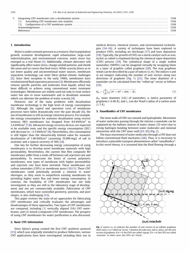
Fig. 1. Letters (n, m) indicate the number of unit vectors in an infinite graphene
sheet and Ch is a ‘rolled up’ vector. T denotes the tube axis, and a1 and a2 are the unit
vectors of graphene. If m = 0, the CNTs are called ‘zigzag’. If n = m, the CNTs are called
‘armchair’. In other cases, the CNTs are ‘chiral’.
1. Introduction
Water is under constant pressure as a resource. Due to populationgrowth, economic development, rapid urbanization, large-scaleindustrialization, and environmental concerns, water stress hasemerged as a real threat [1]. Additionally, climate aberrance willsignificantly affect water stress, change rainfall patterns, and shrinkthe snow and ice covers that feed rivers. While scarcity drives us touse lower quality and unconventional water sources, membraneseparation technology can meet these global climate challenges[2]. Since their inception in the early 1960s, membranes haverevolutionized fluid separation processes [3]. Membranes efficientlyremove specific particles and molecules from liquids, which hasbeen difficult to achieve using conventional water treatmenttechnologies. Membranes are widely used not only to treat surfacewater but also to reuse wastewater and to desalinate seawaterwhich can alleviate the problem of water scarcity [4].
However, one of the main problems with desalinationmembrane technology is the high level of energy consumption[5]. Although the capital and operation costs of membraneprocesses have fallen dramatically over the past decade [6], theuse of membranes is still an energy-intensive process. For example,the energy consumption for seawater desalination using reverseosmosis (RO) membranes has dropped from 8.0 kWh/m3 to3.4 kWh/m3 [7,8]. Advanced energy recovery devices are expectedto be available soon, and the specific energy consumption (SEC)will decrease to <2.5 kWh/m3 [9]. Nevertheless, this consumptionis still higher than the theoretically limited value for seawaterdesalination of 1.06 kWh/m3 (assuming 35,000 mg/L of salt inseawater and a typical recovery of 50%) [4].
One key for further decreasing energy consumption of usingmembranes is to develop novel membrane materials with highpermeability. Nevertheless, the current thin film composite ROmembranes suffer from a trade-off between salt rejection rate andpermeability. To overcome the limits of current polymericmembranes, new types of membrane with higher permeabilityand rejection rate have been invented. These membranes usecarbon nanotubes (CNTs) as membrane pores [10,11]. These CNTmembranes could potentially provide a solution to watershortages, as they seem to outperform existing membranes byproviding higher water flux and lower energy consumption. Incontrast, the feasibility of CNT membranes has not fullyinvestigated, as they are still in the laboratory stage of develop-ment and not yet commercially available. Fabrication of CNTmembranes, which have controlled geometry, porosity, and poreshapes, is also challenging [12].
This paper reviews the state-of-art approaches for fabricatingCNT membranes and critically evaluates the advantages anddisadvantages of these approaches. Two types of CNT membranesare compared, including (1) vertically aligned (VA) CNT mem-branes, and (2) mixed (composite) CNT membranes. The prospectof using CNT membranes for water purification is also discussed.
2. Basic CNT information
Since Iijima’s group created the first CNT synthesis protocol[13], which was originally intended to produce fullerenes, variousCNT applications have been investigated, including their use in
medical devices, chemical sensors, and environmental technolo-gies [14–16]. A variety of techniques have been explored toproduce CNTs, including arc discharge [17] and laser deposition[18]. Typically, the growth of CNTs on a metal catalyst such as iron,nickel, or cobalt is employed during the chemical vapor deposition(CVD) process [19]. The cylindrical shape of a single wallednanotubes (SWNTs) can be imagined virtually by wrapping themin a layer of graphite called graphene [20]. The way graphenewinds can be described by a pair of indices (n, m). The indices n andm are integers indicating the number of unit vectors along twodirections of graphene (Fig. 1) [21]. The inner diameter of ananotube can be calculated from the ‘‘rolled up’’ vector as follows[22].
din ¼a
p
� � ffiffiffiffiffiffiffiffiffiffiffiffiffiffiffiffiffiffiffiffiffiffiffiffiffiffiffiffiffiffiffiffiffiffiffiffiffiffiffiffiffiffiffiffiffiffiffiðn2 þ m2 þ nmÞ � 2rc
q(1)
din, inner diameter (I.D.) of nanotubes; a, lattice parameter ofgraphene (=2.46 A); and rc, van der Waal’s radius of a carbon atom(1.7 A).
3. Nanofluidics of CNT membranes
The inner walls of CNTs are smooth and hydrophobic. Movementof water molecules passing through the interior a nanotube can beexplained by the ballistic motion of water chains (1D wire) due tostrong hydrogen bonding between water molecules and minimalinteraction with the CNT inner wall [23–25] (Fig. 2).
The mass movement of water molecules through a CNT does notfollow conventional fluid mechanics [26]. Thus, it is necessary tointroduce a plausible transport phenomenon called ‘‘nanofluidics’’.In this novel theory, it is assumed that the fluid flowing through a

Fig. 3. Conceptual structures of CNT membranes. (a) Vertically aligned (VA) CNT
membranes, and (b) mixed (composite) CNT membranes.
Fig. 2. Movement of water molecules through a SWNT.
Reprinted with permission from [25].
Table 1Comparison of vertically aligned (VA) CNT membranes and mixed (composite)
CNT membranes.
VA CNT membranes Mixed CNT membranes
� CNTs are aligned vertically � CNTs are mixed with polymeric
materials
� CNTs’ forest is compacted
densely
� Composite layers with PSf membrane
and non-woven support
� Water flux is supposed to be
fast drastically
� Water flux is moderately fast
� Functional group can be attached
at the tip of CNTs or on the
membrane surface conveniently
� Low (or anti-) fouling membrane
� Fabrication procedures are
complicated
� Fabrication processes are
conveniently simple
� May need specially adjusted
operating system
� Operationally feasible to the
conventional membrane process
C.H. Ahn et al. / Journal of Industrial and Engineering Chemistry 18 (2012) 1551–1559 1553
nano-channel has a slip length with no friction [27]. Adopting theslip-flow condition, the Hagen–Poiseuille equation can be used asfollows [26]:
Q slip ¼pðd=2Þ4 þ 4ðd=2Þ3 � LSðdÞ
8m�DP
L(2)
Qslip, water flux depending on slip length; d, diameter of the nano-channel; DP, pressure difference between both ends of the nano-channel; m, viscosity of water; and L, the length of nano-channel.
The slip length (LS (d)) can be computed as follows:
LSðdÞ ¼ LS;1 þC
d3(3)
LS,1, slip length of the graphene surface (assumed to be 30 nm);and C is a fitting parameter. Additionally, the diffusion coefficientof water molecules is estimated as DH2O ¼ 0:9423 � 10�9 m2=s fora 2.1 nm diameter nanotube [28].
In this manner, the CNT membrane uses the inner and/or outersurface of nanotubes as nano-channels for transporting fluid. Withthis configuration, applications of the CNT membrane may not belimited to desalination processes. Additionally, it may be feasibleto extend the use of CNT membranes to include separationtechnologies for oil and gases [29–31].
4. Fabrication of CNT membranes
4.1. Types of CNT membranes
CNTs can be classified into two major categories according tothe fabrication methods; (1) vertically aligned CNT membranes,and (2) mixed (composite) CNT membranes. For VA-CNTmembranes, nanotubes are arranged straight up and perpendicularto the membrane surface. In this configuration, nanotubes arebound to each other by an organic or inorganic filler material. Onthe other hand, mixed-CNT membranes have a structure similar tothat of the thin-film composite RO membranes, where the top layeris mixed with nanotubes and a polymer such as polyamide (PA).Conceptual images of both CNT membranes are shown in Fig. 3.
The features of VA-CNT membranes and mixed-CNT mem-branes are summarized in Table 1. One important advantage ofVA-CNT membranes is that water flux should be very rapid due tothe short nano-channel length and compactness of the nanotubeforest. The VA-CNT membrane was initially attempted due to thenanofluidics, but fabrication made it difficult to produce the largequantities needed for commercialization. Meanwhile, the mixed-CNT membrane has its own merits such as a relatively simplemanufacturing procedure and similarity to existing membraneprocesses. Therefore, more attention must be given to mixed-CNTmembranes.
C.H. Ahn et al. / Journal of Industrial and Engineering Chemistry 18 (2012) 1551–15591554
4.2. Vertically aligned CNT membranes
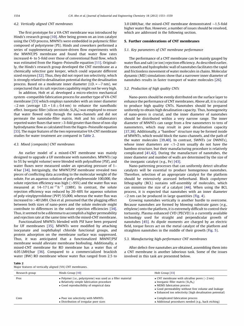
The first prototype for a VA-CNT membrane was introduced byHinds’s research group [10]. After being grown on an iron catalystusing the CVD process, MWNTs were embedded in polymeric fillercomposed of polystyrene (PS). Hinds and coworkers performed aseries of supplementary pressure-driven flow experiments withthe MWNT/PS membrane and found that water flow ratesincreased 4- to 5-fold over those of conventional fluid flow, whichwas estimated from the Hagen–Poiseuille equation [11]. Original-ly, the Hinds’s research group developed the CNT membrane as achemically selective gate keeper, which could separate differentsized enzymes [32]. Thus, they did not report ion selectivity, whichis strongly related to desalination potential during the desalinationprocess. Based on a moderate inner diameter (I.D. = �7 nm), weconjectured that its salt rejection capability might not be very high.
In addition, Holt et al. developed a micro-electro mechanicalsystem -compatible fabrication process for another type of VA-CNTmembrane [33] which employs nanotubes with an inner diameter<2 nm (average I.D. = 1.6 � 0.4 nm) to enhance the nanofluidiceffect. Inorganic filler (silicon nitride, Si3N4) was employed to ensurethat water flowed only through the nano-channels and did notpermeate the nanotube-filler matrix. Holt and his collaboratorsreported water fluxes that were >3-fold greater than those of non-sliphydrodynamic flow as calculated from the Hagen–Poiseuille equation[33]. The major features of the two representative VA-CNT membranestudies for water treatment are compared in Table 2.
4.3. Mixed (composite) CNT membranes
An earlier model of a mixed-CNT membrane was mainlydesigned to upgrade a UF membrane with nanotubes. MWNTs (upto 5% by weight volume) were blended with polysulfone (PSf), andwater fluxes were measured under an operating pressure of 1–4 bar [34]. Intriguingly, the MWNT/PSf membrane revealed twopieces of conflicting data according to the molecular weight of thesolute. For an aqueous solution of poly-ethyleneoxide 100,000, thesolute rejection efficiency was high (>95%) and the water flux wasmeasured at 14–17 L m�2 h�1 (LMH). In contrast, the soluterejection efficiency was reduced by 20–60% for aqueous solutionof poly-vinylpyrrolidone (PVP) 55,000, whereas the water flux wasincreased to >40 LMH. Choi et al. presumed that the plugging effectbetween both sizes of nano-pores and the solute molecule mightcontribute to differences in the solute rejection efficiencies [34].Thus, it seemed to be a dilemma to accomplish a higher permeabilityand rejection rate at the same time with the mixed-CNT membrane.
Functionalized MWNTs blended with PSf have been preparedfor UF membranes [35]. MWNTs were modified by attachingisocyanate and isophthaloyl chloride functional groups, andprotein adsorption on the membrane surface was suppressed.Thus, it was anticipated that a functionalized MWNT/PSfmembrane would alleviate membrane biofouling. Additionally, amixed-CNT membrane for RO membrane has a water flux of4.05 LMH/bar [36]. Compared to a commercialized brackishwater (BW) RO membrane whose water flux ranged from 2.5 to
Table 2Major features of vertically aligned (VA) CNT membranes.
Research group Hinds Group [10]
Pros � Polymer (i.e., polystyrene) was used as a filler m
� Relatively simple fabrication procedure
� Good reproducibility of empirical data
Cons � Poor ion selectivity with MWNTs
� Distribution of irregular pore sizes
3.0 LMH/bar, the mixed-CNT membrane demonstrated �1.5-foldhigher water flux. However, a number of issues should be resolved,which are addressed in the following section.
5. Further considerations of CNT membranes
5.1. Key parameters of CNT membrane performance
The performance of a CNT membrane can be mainly gauged bywater flux and salt (or ion) rejection efficiency. As described earlier,the smooth and hydrophobic wall of nanotubes facilitates the rapidand frictionless movement of water molecules in chains. Moleculardynamic (MD) simulations show that a narrower inner diameter ofnanotubes results in faster transport of water molecules [26].
5.2. Production of high quality CNTs
Nano-pores should be evenly distributed on the surface layer toenhance the performance of CNT membranes. Above all, it is crucialto produce high quality CNTs. Nanotubes should be prepareduniformly to obtain high desalination capacity. Thus, homogeneityof nano-pores is crucial, and the inner diameter of nanotubesshould be distributed within a very narrow range. The innerdiameter of MWNTs can range from a few nanometers to tens ofnanometers, which may result in poor desalination capacity[37,38]. Additionally, a ‘‘bamboo’’ structure may be formed insideof MWNTs, which would block the nano-channels, and the path ofthe water molecules [39,40]. In contrast, SWNTs (or DWNTs),whose inner diameters are <1–2 nm usually do not have thebamboo structure, but their manufacturing procedure is relativelycomplicated [41,42]. During the manufacture of nanotubes, theinner diameter and number of walls are determined by the size ofthe inorganic catalyst (e.g., Fe) [43].
Nano-patterning processes that can uniformly detect ultrafinecatalysts will be essential to produce homogenous nanotubes.Therefore, selection of an appropriate catalyst for the platformshould be extensively assessed beforehand. Block copolymerlithography (BCL) sustains self-assembly of molecules, whichcan minimize the size of a catalyst [44]. When using the BCLprocess, it is expected that nanotubes with an inner diameter<2 nm can be produced in large quantities (Fig. 4).
Growing nanotubes vertically is another hurdle to overcome.Because nanotubes are formed by blowing substrate gases (e.g.,ethylene) onto the platform, it is extremely difficult to control theirtortuosity. Plasma enhanced CVD (PECVD) is a currently availabletechnology used for straight and perpendicular growth ofnanotubes [45]. As dipole moments are charged by an electricfield, torque forces act on the metal catalyst of the platform andstraighten nanotubes in the middle of their growth (Fig. 5).
5.3. Manufacturing high-performance CNT membranes
After defect-free nanotubes are obtained, assembling them intoa CNT membrane is another laborious task. Some of the issuesinvolved in this task are presented below.
Holt Group [33]
aterial � CNT membrane with ultrafine pores (<2 nm)
� Inorganic filler matrix (Si3N4)
� MEMS fabrication process
� Good permeability without free volume and leakage
� Enhanced ion selectivity (high desalination potential)
� Complicated fabrication process
� Additional procedures needed (e.g., back etching)

Fig. 4. Proposed manufacturing process for vertically aligned (VA) CNT membranes using a block copolymer lithography method.
Reprinted with permission from [44].
Fig. 5. Vertical growth of CNTs by using plasma enhanced chemical vapor deposition (PECVD) process.
Reprinted with permission from [45].
C.H. Ahn et al. / Journal of Industrial and Engineering Chemistry 18 (2012) 1551–1559 1555
5.3.1. CNT density
As the number of nanopores (or nano-channels) increases,water flux is augmented proportionally. That is, CNT density is akey parameter determining permeability of a CNT membrane,whereas pore size is one of the main factors enhancing rejectionefficiency. It is essential to augment CNT density (or areal density)to render the highest possible surface porosity. Consideringpreviously reported values, the CNT density should be above�1011 CNT cm�2 to attain water flux of 30–100 LMH [22,33]. Asnanotechnology improves, the CNT density will continue toincrease along with surface porosity. Falconer’s research groupfound a novel way of consolidating a nanotube forest and reported
a density of 2.9 � 1012 CNT cm�2 [46]. The main components ofvarious CNT membranes are compared in Table 3 [10,33,47,48].Improvements in CNT membranes are mainly achieved byincreasing CNT density from �2 � 109 to �7 � 1010 and byemploying SWNT or DWNT instead of MWNT.
5.3.2. Aggregation of nanotubes
Due to van der Waal’s forces, nanotubes tend to agglomeratetogether, and due to the strong agglomeration propensity, eachcane of nanotubes should be sufficiently separated beforehand toform CNTs and a filler matrix, which may not be convenientlyachievable.
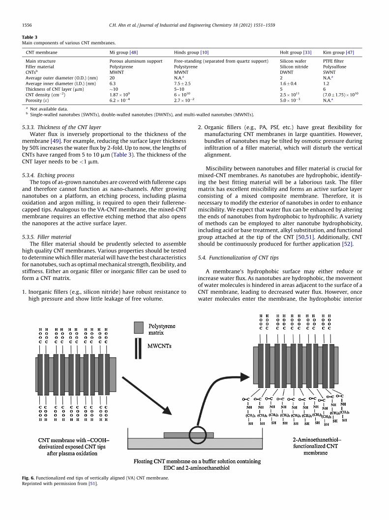
Table 3Main components of various CNT membranes.
CNT membrane Mi group [48] Hinds group [10] Holt group [33] Kim group [47]
Main structure Porous aluminum support Free-standing (separated from quartz support) Silicon wafer PTFE filter
Filler material Polystyrene Polystyrene Silicon nitride Polysulfone
CNTsb MWNT MWNT DWNT SWNT
Average outer diameter (O.D.) (nm) 20 N.A.a 2 N.A.a
Average inner diameter (I.D.) (nm) 6.3 7.5 � 2.5 1.6 � 0.4 1.2
Thickness of CNT layer (mm) �10 5–10 5 6
CNT density (cm�2) 1.87 � 109 6 � 1010 2.5 � 1011 (7.0 � 1.75) � 1010
Porosity (e) 6.2 � 10�4 2.7 � 10�2 5.0 � 10�3 N.A.a
a Not available data.b Single-walled nanotubes (SWNTs), double-walled nanotubes (DWNTs), and multi-walled nanotubes (MWNTs).
C.H. Ahn et al. / Journal of Industrial and Engineering Chemistry 18 (2012) 1551–15591556
5.3.3. Thickness of the CNT layer
Water flux is inversely proportional to the thickness of themembrane [49]. For example, reducing the surface layer thicknessby 50% increases the water flux by 2-fold. Up to now, the lengths ofCNTs have ranged from 5 to 10 mm (Table 3). The thickness of theCNT layer needs to be <1 mm.
5.3.4. Etching process
The tops of as-grown nanotubes are covered with fullerene capsand therefore cannot function as nano-channels. After growingnanotubes on a platform, an etching process, including plasmaoxidation and argon milling, is required to open their fullerene-capped tips. Analogous to the VA-CNT membrane, the mixed-CNTmembrane requires an effective etching method that also opensthe nanopores at the active surface layer.
5.3.5. Filler material
The filler material should be prudently selected to assemblehigh quality CNT membranes. Various properties should be testedto determine which filler material will have the best characteristicsfor nanotubes, such as optimal mechanical strength, flexibility, andstiffness. Either an organic filler or inorganic filler can be used toform a CNT matrix.
1. Inorganic fillers (e.g., silicon nitride) have robust resistance tohigh pressure and show little leakage of free volume.
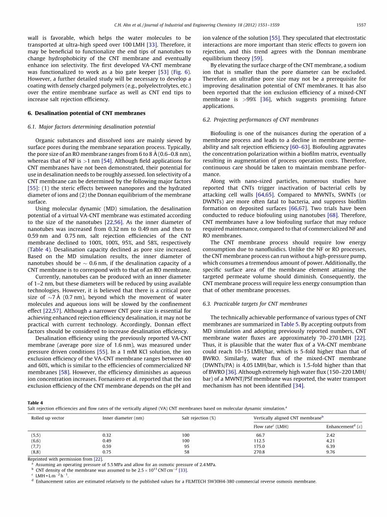
Fig. 6. Functionalized end tips of vertically aligned (VA) CNT membrane.
Reprinted with permission from [51].
2. Organic fillers (e.g., PA, PSf, etc.) have great flexibility formanufacturing CNT membranes in large quantities. However,bundles of nanotubes may be tilted by osmotic pressure duringinfiltration of a filler material, which will disturb the verticalalignment.
Miscibility between nanotubes and filler material is crucial formixed-CNT membranes. As nanotubes are hydrophobic, identify-ing the best fitting material will be a laborious task. The fillermatrix has excellent miscibility and forms an active surface layerconsisting of a mixed composite membrane. Therefore, it isnecessary to modify the exterior of nanotubes in order to enhancemiscibility. We expect that water flux can be enhanced by alteringthe ends of nanotubes from hydrophobic to hydrophilic. A varietyof methods can be employed to alter nanotube hydrophobicity,including acid or base treatment, alkyl substitution, and functionalgroup attached at the tip of the CNT [50,51]. Additionally, CNTshould be continuously produced for further application [52].
5.4. Functionalization of CNT tips
A membrane’s hydrophobic surface may either reduce orincrease water flux. As nanotubes are hydrophobic, the movementof water molecules is hindered in areas adjacent to the surface of aCNT membrane, leading to decreased water flux. However, oncewater molecules enter the membrane, the hydrophobic interior
C.H. Ahn et al. / Journal of Industrial and Engineering Chemistry 18 (2012) 1551–1559 1557
wall is favorable, which helps the water molecules to betransported at ultra-high speed over 100 LMH [33]. Therefore, itmay be beneficial to functionalize the end tips of nanotubes tochange hydrophobicity of the CNT membrane and eventuallyenhance ion selectivity. The first developed VA-CNT membranewas functionalized to work as a bio gate keeper [53] (Fig. 6).However, a further detailed study will be necessary to develop acoating with densely charged polymers (e.g., polyelectrolytes, etc.)over the entire membrane surface as well as CNT end tips toincrease salt rejection efficiency.
6. Desalination potential of CNT membranes
6.1. Major factors determining desalination potential
Organic substances and dissolved ions are mainly sieved bysurface pores during the membrane separation process. Typically,the pore size of an RO membrane ranges from 6 to 8 A (0.6–0.8 nm),whereas that of NF is >1 nm [54]. Although field applications forCNT membranes have not been demonstrated, their potential foruse in desalination needs to be roughly assessed. Ion selectivity of aCNT membrane can be determined by the following major factors[55]: (1) the steric effects between nanopores and the hydrateddiameter of ions and (2) the Donnan equilibrium of the membranesurface.
Using molecular dynamic (MD) simulation, the desalinationpotential of a virtual VA-CNT membrane was estimated accordingto the size of the nanotubes [22,56]. As the inner diameter ofnanotubes was increased from 0.32 nm to 0.49 nm and then to0.59 nm and 0.75 nm, salt rejection efficiencies of the CNTmembrane declined to 100%, 100%, 95%, and 58%, respectively(Table 4). Desalination capacity declined as pore size increased.Based on the MD simulation results, the inner diameter ofnanotubes should be � 0.6 nm, if the desalination capacity of aCNT membrane is to correspond with to that of an RO membrane.
Currently, nanotubes can be produced with an inner diameterof 1–2 nm, but these diameters will be reduced by using availabletechnologies. However, it is believed that there is a critical poresize of �7 A (0.7 nm), beyond which the movement of watermolecules and aqueous ions will be slowed by the confinementeffect [22,57]. Although a narrower CNT pore size is essential forachieving enhanced rejection efficiency desalination, it may not bepractical with current technology. Accordingly, Donnan effectfactors should be considered to increase desalination efficiency.
Desalination efficiency using the previously reported VA-CNTmembrane (average pore size of 1.6 nm), was measured underpressure driven conditions [55]. In a 1 mM KCl solution, the ionexclusion efficiency of the VA-CNT membrane ranges between 40and 60%, which is similar to the efficiencies of commercialized NFmembranes [58]. However, the efficiency diminishes as aqueousion concentration increases. Fornasiero et al. reported that the ionexclusion efficiency of the CNT membrane depends on the pH and
Table 4Salt rejection efficiencies and flow rates of the vertically aligned (VA) CNT membranes
Rolled up vector Inner diameter (nm) Salt reject
(5,5) 0.32 100
(6,6) 0.49 100
(7,7) 0.59 95
(8,8) 0.75 58
Reprinted with permission from [22].a Assuming an operating pressure of 5.5 MPa and allow for an osmotic pressure of 2b CNT density of the membrane was assumed to be 2.5 � 1011 CNT cm�2 [33].c LMH = L m�2 h�1.d Enhancement ratios are estimated relatively to the published values for a FILMTEC
ion valence of the solution [55]. They speculated that electrostaticinteractions are more important than steric effects to govern ionrejection, and this trend agrees with the Donnan membraneequilibrium theory [59].
By elevating the surface charge of the CNT membrane, a sodiumion that is smaller than the pore diameter can be excluded.Therefore, an ultrafine pore size may not be a prerequisite forimproving desalination potential of CNT membranes. It has alsobeen reported that the ion exclusion efficiency of a mixed-CNTmembrane is >99% [36], which suggests promising futureapplications.
6.2. Projecting performances of CNT membranes
Biofouling is one of the nuisances during the operation of amembrane process and leads to a decline in membrane perme-ability and salt rejection efficiency [60–63]. Biofouling aggravatesthe concentration polarization within a biofilm matrix, eventuallyresulting in augmentation of process operation costs. Therefore,continuous care should be taken to maintain membrane perfor-mance.
Along with nano-sized particles, numerous studies havereported that CNTs trigger inactivation of bacterial cells byattacking cell walls [64,65]. Compared to MWNTs, SWNTs (orDWNTs) are more often fatal to bacteria, and suppress biofilmformation on deposited surfaces [66,67]. Two trials have beenconducted to reduce biofouling using nanotubes [68]. Therefore,CNT membranes have a low biofouling surface that may reducerequired maintenance, compared to that of commercialized NF andRO membranes.
The CNT membrane process should require low energyconsumption due to nanofluidics. Unlike the NF or RO processes,the CNT membrane process can run without a high-pressure pump,which consumes a tremendous amount of power. Additionally, thespecific surface area of the membrane element attaining thetargeted permeate volume should diminish. Consequently, theCNT membrane process will require less energy consumption thanthat of other membrane processes.
6.3. Practicable targets for CNT membranes
The technically achievable performance of various types of CNTmembranes are summarized in Table 5. By accepting outputs fromMD simulation and adopting previously reported numbers, CNTmembrane water fluxes are approximately 70–270 LMH [22].Thus, it is plausible that the water flux of a VA-CNT membranecould reach 10–15 LMH/bar, which is 5-fold higher than that ofBWRO. Similarly, water flux of the mixed-CNT membrane(DWNTs/PA) is 4.05 LMH/bar, which is 1.5-fold higher than thatof BWRO [36]. Although extremely high water flux (150–220 LMH/bar) of a MWNT/PSf membrane was reported, the water transportmechanism has not been identified [34].
based on molecular dynamic simulation.a
ion (%) Vertically aligned CNT membraneb
Flow ratec (LMH) Enhancementd (e)
66.7 2.42
112.5 4.21
175.0 6.39
270.8 9.76
.4 MPa.
H SW30H4-380 commercial reverse osmosis membrane.

Table 5Technically achievable performances according to types of CNT membranes.
CNT membrane Vertically aligned Mixed (composite)
Water fluxa (LMH/bar) 10–15 4–6
Salt rejection BWRO levelb BWRO levelb
Antifoulingc N.A. 30%
Membrane element type Plate and frame (�1 m3) Spiral wound (8 in.)
a Assuming that nanotubes of inner diameter 1 nm are employed and CNT
density is 2.5 � 1011 CNT cm�2 for both CNT membranes [33].b Salt rejection efficiency 93% at an applied pressure of 0.5–3.0 MPa.c Reduction of biofouling brings to high energy efficiency.
C.H. Ahn et al. / Journal of Industrial and Engineering Chemistry 18 (2012) 1551–15591558
It seems that VA-CNT membranes will have salt rejectionefficiencies similar to those of commercialized NF membranes.Ultrafine nanotubes (inner diameter �1 nm) should be employedand their surface charge should be elevated to enhance desalina-tion capacity to the level of an RO membrane. By upgradingnanotubes with various functional groups and surface modifica-tions, the salt rejection efficiency of a VA-CNT membrane shouldreach that of a BWRO membrane.
The active surface layer of a mixed CNT membrane is composedof a mixture of nanotubes and polymers (e.g., PA). By employingtechniques analogous to those described above, it may not be a bigchallenge to increase the salt rejection efficiency of mixed CNTmembranes to correspond to that of a BWRO membrane.
7. Integrating CNT membranes into a desalination system
7.1. Assembling CNT membranes into modules
A prototype manufacturing process for a VA-CNT membranecan be described as follows. Fully grown nanotubes are harvestedafter the PECVD process, and filler material infiltrates into the CNTforest. Then, small pieces of CNT membrane would be patched intoplank or plate shapes. Judging from the manufacturing procedures,conventional membrane modules may not be applicable for usewith VA-CNT membranes. In this manner, we postulate that aplate-and-frame type will be suitable as a VA-CNT membranemodule, which can be adapted from the disc-tube module of thePall Corp. (Fig. 7) [69]. Plate shaped CNT membranes would be
Fig. 7. Cross-sectional view of a
laminated in a cylindrical tank and permeates would be collectedfrom a drainage pipeline in the core.
In contrast, we expect that a module configuration of a mixed-CNT membrane may not deviate much from the conventional typesof PA-RO membranes. Currently, the spiral wound type isemployed worldwide in the RO process. A typical manufacturingprocess for a PA-RO membrane can be described as follows [70].First, a membrane film is formed by applying a PSf layer on apolyester support during the ‘‘casting’’ process, which can then beused as an UF membrane. Second, PA is coated by interfacialpolymerization as a skin layer on top of the PSf layer, which iscalled the ‘‘coating’’ process. Subsequently, the membrane sheet isscrolled in a leaf form, producing a spiral-wound type module,which is called the ‘‘rolling’’ process. Assuming an analogousconveyor line can be used for the mixed CNT membrane, only thecoating process would be retrofitted. That is, nanotubes are mixedwith a polymer (e.g., PA) solution and their mixture forms an activelayer on the membrane surface. Alternately, additional proceduresmay be required for mixing nanotubes and polymer in advance,and the mixture would be coated on the PSf support layer. In eithercase, mixed (composite) CNT membranes would be scrolled inthe rolling process and a spiral-would type module would bemanufactured.
7.2. Configuration of a CNT membrane system
In advance of on-site applications, the manufactured mem-brane module should be assessed for short-term and long-termuse. Short-term examinations include measurements of water fluxand salt rejection efficiency, whereas long-period evaluationsinvolve specific energy consumption rate and module stability.Other operating parameters should be considered, such asdisinfectant and chemical cleaning.
Ultra-high water flux should be considered to integrate the CNTmembrane into water treatment processes. If the water flux isextremely high, dissolved salts will be left over and crystallize,leading to a failure of the system. Additionally, various types ofmembrane modules should be considered in the system configu-ration. By maneuvering the newly developed design program,performances of a CNT membrane could be predicted including the
disc-tube membrane [67].

C.H. Ahn et al. / Journal of Industrial and Engineering Chemistry 18 (2012) 1551–1559 1559
qualities of permeates and concentrates. Eventually, a configura-tion for the whole system will be designed (e.g., arrangement ofvessels).
Along with the operating configuration, the safety of the CNTmembrane is also an important issue to be resolved. Concerns willbe raised about the environmental and health impacts of CNTs thatmay be released from CNT membranes during operation [71,72].Considering the multiple layers and supplementary appurtenancesof CNT membranes, it appears that there is little chance that CNTsare able to pass through a wholly integrated membrane element.Even with numerous efforts for regulating nano-materials, nosafety guidelines for use of CNT membranes in the waterpurification process have been adopted. Thus, an interdisciplinaryapproach should be used to establish a policy for CNT membranetechnology. In the near future, CNT membrane related enterprisesare expected to flourish as safety rules are properly enforced.
Acknowledgements
This research was supported by the WCU (World ClassUniversity) program through a Korea Science and EngineeringFoundation grant funded by the Ministry of Education, Science, andTechnology (400-2008-0230) and the National Research Founda-tion of Korea Grant funded by the Korean Government (NRF-2010-C1AAA01-0029061) and the K-water Research & Business Project(K_RBP-1). We thank John Wiley and Sons, the American ChemicalSociety and IOP Publishing for the permission to publish figuresand tables.
References
[1] C.J. Vorosmarty, P. Green, J. Salisbury, R.B. Lammers, Science 289 (2000) 284.[2] M.A. Shannon, P.W. Bohn, M. Elimelech, J.G. Georgiadis, B.J. Marinas, A.M. Mayes,
Nature 452 (2008) 301.[3] J. Glater, Desalination 117 (1998) 297.[4] M. Elimelech, W.A. Phillip, Science 333 (2011) 712.[5] H. Ludwig, Desalination and Water Treatment 13 (2010) 13.[6] GWI, Desalination Markets 2005–2015, GWI, Oxford, 2004.[7] C. Fritzmann, J. Lowenberg, T. Wintgens, T. Melin, Desalination 216 (2007) 1.[8] R. Semiat, Environmental Science & Technology 42 (2008) 8193.[9] O.M. Al-Hawaj, Desalination and Water Treatment 8 (2009) 131.
[10] B.J. Hinds, N. Chopra, T. Rantell, R. Andrews, V. Gavalas, L.G. Bachas, Science 303(2004) 62.
[11] M. Majumder, N. Chopra, R. Andrews, B.J. Hinds, Nature 438 (2005) 44.[12] M. Majumder, P. Ajayan, Comprehensive Membrane Science and Engineering 1
(2010) 291.[13] S. Iijima, Nature 354 (1991) 56.[14] A.M. Popov, Y.E. Lozovik, S. Fiorito, L.H. Yahia, International Journal of Nanome-
dicine 2 (2007) 361.[15] J. Wang, Electroanalysis 17 (2005) 7.[16] M.S. Mauter, M. Elimelech, Environmental Science & Technology 42 (2008) 5843.[17] T. Ebbesen, P. Ajayan, Nature 358 (1992) 220.[18] T. Guo, P. Nikolaev, A.G. Rinzler, D. Tomanek, D.T. Colbert, R.E. Smalley, The
Journal of Physical Chemistry 99 (1995) 10694.[19] M. Jose Yacaman, M. Miki Yoshida, L. Rendon, J. Santiesteban, Applied Physics
Letters 62 (1993) 202.[20] A. Thess, R. Lee, P. Nikolaev, H. Dai, P. Petit, J. Robert, C. Xu, Y.H. Lee, S.G. Kim, A.G.
Rinzler, Science 273 (1996) 483.[21] en.wikipedia.org/wiki/File:CNTnames.png.[22] B. Corry, The Journal of Physical Chemistry B 112 (2008) 1427.[23] G. Hummer, J.C. Rasaiah, J.P. Noworyta, Nature 414 (2001).[24] J. Kofinger, G. Hummer, C. Dellago, Proceedings of the National Academy of
Sciences 105 (2008) 13218.[25] T.A. Hilder, D. Gordon, S.H. Chung, Small 5 (2009) 2183.
[26] J.A. Thomas, A.J.H. McGaughey, Nano Letters 8 (2008) 2788.[27] J.K. Holt, Advanced Materials 21 (2009) 3542.[28] A. Striolo, Nano Letters 6 (2006) 633.[29] A. Ismail, P.S. Goh, S. Sanip, M. Aziz, Separation and Purification Technology 70
(2009) 12.[30] C. Lee, S. Baik, Carbon 48 (2010) 2192.[31] K. Sears, L. Dumee, J. Schutz, M. She, C. Huynh, S. Hawkins, M. Duke, S. Gray,
Materials 3 (2010) 127.[32] M. Majumder, N. Chopra, B.J. Hinds, ACS Nano 5 (2011) 3867.[33] J.K. Holt, H.G. Park, Y. Wang, M. Stadermann, A.B. Artyukhin, C.P. Grigoropoulos, A.
Noy, O. Bakajin, Science 312 (2006) 1034.[34] J.H. Choi, J. Jegal, W.N. Kim, Journal of Membrane Science 284 (2006) 406.[35] S. Qiu, L. Wu, X. Pan, L. Zhang, H. Chen, C. Gao, Journal of Membrane Science 342
(2009) 165.[36] T.V. Ratto, J.K. Holt, A.W. Szmodis, Membranes with embedded nanotubes for
selective permeability, Google Patents, 2011.[37] C.H. Kiang, M. Endo, P. Ajayan, G. Dresselhaus, M. Dresselhaus, Physical Review
Letters 81 (1998) 1869.[38] P.X. Hou, S.T. Xu, Z. Ying, Q.H. Yang, C. Liu, H.M. Cheng, Carbon 41 (2003) 2471.[39] E.T. Thostenson, Z. Ren, T.W. Chou, Composites Science and Technology 61 (2001)
1899.[40] M. Glerup, M. Castignolles, M. Holzinger, G. Hug, A. Loiseau, P. Bernier, Chemical
Communications (2003) 2542.[41] D.H. Lee, W.J. Lee, S.O. Kim, Nano Letters 9 (2009) 1427.[42] D.H. Lee, W.J. Lee, S.O. Kim, Chemistry of Materials 21 (2009) 1368.[43] E. Kukovitsky, S. L’vov, N. Sainov, V. Shustov, L. Chernozatonskii, Chemical Physics
Letters 355 (2002) 497.[44] D.H. Lee, D.O. Shin, W.J. Lee, S.O. Kim, Advanced Materials 20 (2008) 2480.[45] M. Meyyappan, L. Delzeit, A. Cassell, D. Hash, Plasma Sources Science and
Technology 12 (2003) 205.[46] M. Yu, H.H. Funke, J.L. Falconer, R.D. Noble, Nano Letters 9 (2009) 225.[47] S. Kim, J.R. Jinschek, H. Chen, D.S. Sholl, E. Marand, Nano Letters 7 (2007) 2806.[48] W. Mi, Y. Lin, Y. Li, Journal of Membrane Science 304 (2007) 1.[49] A. Zhu, P.D. Christofides, Y. Cohen, Industrial & Engineering Chemistry Research
48 (2009) 6010.[50] M. Majumder, N. Chopra, B.J. Hinds, Journal of the American Chemical Society 127
(2005) 9062.[51] J.M. Lee, S.J. Kim, J.W. Kim, P.H. Kang, Y.C. Nho, Y.S. Lee, Journal of Industrial and
Engineering Chemistry 15 (2009) 66.[52] L.S. Ying, M.A.M. Salleh, S.B.A. Rashid, Journal of Industrial and Engineering
Chemistry 17 (2011) 367.[53] N. Chopra, M. Majumder, B.J. Hinds, Advanced Functional Materials 15 (2005)
858.[54] S.H. Kim, S.Y. Kwak, T. Suzuki, Environmental Science & Technology 39 (2005)
1764.[55] F. Fornasiero, H.G. Park, J.K. Holt, M. Stadermann, C.P. Grigoropoulos, A. Noy, O.
Bakajin, Proceedings of the National Academy of Sciences 105 (2008) 17250.[56] B. Corry, Energy and Environmental Science 4 (2011) 751.[57] M.E. Selvan, D. Keffer, S. Cui, S. Paddison, Molecular Simulation 36 (2010) 568.[58] N. Hilal, H. Al-Zoubi, A. Mohammad, N. Darwish, Desalination 184 (2005) 315.[59] F. Donnan, Journal of Membrane Science 100 (1995) 45.[60] H. Ridgway, H. Flemming, Membrane Biofouling, McGraw-Hill, Washington, DC,
1996.[61] J. Patching, G. Fleming, Biofilms in Medicine, Industry and Environmental Bio-
technology, IWA Publishing, UK, 2003, p. 568.[62] M. Herzberg, M. Elimelech, Journal of Membrane Science 295 (2007) 11.[63] J. Vrouwenvelder, S. Manolarakis, J. Van der Hoek, J. Van Paassen, W. Van der
Meer, J. Van Agtmaal, H. Prummel, J. Kruithof, M. Van Loosdrecht, Water Research42 (2008) 4856.
[64] S. Kang, M. Pinault, L.D. Pfefferle, M. Elimelech, Langmuir 23 (2007) 8670.[65] Q. Li, S. Mahendra, D.Y. Lyon, L. Brunet, M.V. Liga, D. Li, P.J.J. Alvarez, Water
Research 42 (2008) 4591.[66] G. Jia, H. Wang, L. Yan, X. Wang, R. Pei, T. Yan, Y. Zhao, X. Guo, Environmental
Science & Technology 39 (2005) 1378.[67] D.F. Rodrigues, M. Elimelech, Environmental Science & Technology 44 (2010)
4583.[68] P.B. Messersmith, M. Textor, Nature Nanotechnology 2 (2007) 138.[69] http://www.pall.com.[70] R.F. Fibiger, J. Koo, D.J. Forgach, R.J. Petersen, D.L. Schmidt, R.A. Wessling, T.F.
Stocker, Novel polyamide reverse osmosis membranes, Google Patents, 1988.[71] C. Lam, J.T. James, R. McCluskey, S. Arepalli, R.L. Hunter, CRC Critical Reviews in
Toxicology 36 (2006) 189.[72] K. Kostarelos, Nature Biotechnology 26 (2008) 774.