Embed Size (px)
DESCRIPTION
research article
Citation preview
7212019 Journal of Cleaner ProductionExperimental Investigation On
httpslidepdfcomreaderfulljournal-of-cleaner-productionexperimental-investigation-on 111
Experimental investigation on removing cutting 1047298uid from turning of
Inconel 725 with coated carbide tools
Ahmadreza Hosseini Tazehkandi Farid Pilehvarian Behnam Davoodi
Department of Manufacturing Engineering Faculty of Mechanical Engineering University of Tabriz Tabriz Iran
a r t i c l e i n f o
Article history
Received 29 November 2013
Received in revised form
12 May 2014
Accepted 31 May 2014
Available online 11 June 2014
Keywords
Dry machining
Biodegradable vegetable oil
Coated and uncoated tool
Cutting forces
Surface roughness
Response surface methodology
a b s t r a c t
The aim of this study is to investigate the feasibility of removing cutting 1047298
uids from turning process of Inconel 725 For this purpose the effects of machining parameters such as cutting speed feed rate and
depth of cut on machining forces were investigated These forces include feed force thrust force and
cutting force In addition surface roughness was examined in both conditions of dry machining with
coated tool and wet machining with uncoated tool Results showed that in contrast with conventional
machining processes cutting speed and coating of tool are the most important parameters in removing
cutting 1047298uids The data obtained from the tests indicated that in machining with coated tool with special
ranges of parameters cutting 1047298uid could be completely removed from machining process Furthermore
for both of dry and wet machining the optimum ranges of parameters were presented in order to reach a
green manufacturing process
copy 2014 Elsevier Ltd All rights reserved
1 Introduction
The main aim of all machining operations is to reach to lower
machining costs as well as improved quality and productivity This
can be achieved by machining at the highest cutting speed without
affecting tool life reducing the scrap parts and minimize down-
time During machining process lots of parameters could affect the
cutting condition Although machining operations can be carried
out ldquodryrdquo cutting 1047298uids have been used extensively and play a
signi1047297cant role in machining areas Cutting 1047298uids affect the pro-
ductivity of machining operations tool life and quality of work-
piece Also they prevent the cutting tool and machine from
overheating The proper application of cutting 1047298uids provides
higher cutting speeds and higher feed rates In general a successful
cutting 1047298uid must not only improve the machining process per-formance but also ful1047297ll a number of requirements which are non-
toxic non-harmful to health of operators not a 1047297re hazard not
smoke or fog in use and costless One of the drawbacks of using
cutting 1047298uids is the waste disposal after being used (Kuram et al
2013)
The use of cutting 1047298uids repeatedly over time induces theirchemical changes These changes are due to environmental effects
contamination from metal chips and tramp oil The growth of
bacteria and yeast becomes environmental hazard and also
adversely affects the cutting 1047298uids Cutting 1047298uids gradually degrade
in quality and as they lose their quality the disposal of them is
mandatory Waste disposal of cutting 1047298uids is expensive and has
negative effects on the environment The focus on lubricants has
shifted from biodegradability to renewability over the years as a
result of the changes in human beings environmental thinking
(Davim 2013) Biodegradability is the most important aspect with
regard to the environment and human health Considering biode-
gradability esters and vegetable oils are more appropriate to
formulate cutting 1047298uids because they are readily biodegradable in
contrast to the mineral synthetic and semi-synthetic cutting 1047298uids(Lawal et al 2013)
Nickel based superalloys such as Inconel 725 are widely
employed in the aerospace industry in particular in the hot sec-
tions of gas turbine engines this is due to their high temperature
strength and high corrosion resistance They are known as one of
the most dif 1047297cult-to-cut materials In machining dif 1047297cult-to-cut
materials the coolant acquisition use disposal and the cleaning
of the machined components lead to signi1047297cant costs four times as
many as cutting operations of other materials The machining
manufacturers aim is to take the advantages of dry cutting by
eliminating or minimizing the amount of cutting 1047298uids and to
Corresponding author Tel thorn98 914 391 19 31 fax thorn98 914 148 72 63
E-mail addresses AhmadrezaHosseini89mstabrizuacir ahmadreza_
hosseini89yahoocom (A Hosseini Tazehkandi) FaridPilehvarian90mstabrizu
acir (F Pilehvarian) bdavooditabrizuacir (B Davoodi)
Contents lists available at ScienceDirect
Journal of Cleaner Production
j o u r n a l h o m e p a g e w w w e l s e v i e r co m l o c a t e j c l e p r o
httpdxdoiorg101016jjclepro201405098
0959-6526copy
2014 Elsevier Ltd All rights reserved
Journal of Cleaner P roduction 80 (2014) 271e281
7212019 Journal of Cleaner ProductionExperimental Investigation On
httpslidepdfcomreaderfulljournal-of-cleaner-productionexperimental-investigation-on 211
improve material removal rate with high speed machining
(Devillez et al 2011) Furthermore costs relating to using cutting
1047298uids through machining of nickel based superalloys are 7e17
percent of total machining cost (Weinert et al 2004) So it clearly
reveals how dry machining can reduce the costs and increase the
productivity
The costs associated with the use of cutting 1047298uids is estimated
to be several billion dollar per a year Consequently elimination
on the use of cutting 1047298uids if possible can be a signi1047297cant
economic incentive Considering the high cost associated with
the use of cutting 1047298uids and projected escalating costs when the
stricter environmental laws are enforced the choice seems
obvious A moratorium on the use of cutting 1047298uids and chemicals
harmful to the personnel and costly to remediate and by prac-
ticing dry machining This would prepare industry for
manufacturing in the year 2000 and beyond namely green
manufacturing or environmentally friendly manufacturing
(Davim 2013)
Dry machining means that no cutting 1047298uid is used during pro-
cess For economic and environmental reasons machining process
is carried out without any cutting 1047298uid but dry machininghas some
disadvantages Certain grades of carbides and coated carbide cut-
ting tools are developed for the use in dry machining (Groover2007) Dry machining is preferable to operate at lower cutting
speeds and produce a low production rate in order to prolong tool
life During dry machining process temperature of the cutting tool
is very high and this induces excessive tool wear thus decreasing
tool life Also the chips generated at machining cannot be washed
away and these chips cause deterioration on the machined surface
The problems of cutting 1047298uid contamination and disposal are not
seen in dry machining Dry machining does not lead to the pollu-
tion of atmosphere or water resources Contrary to dry machining
in wet machining (machining with cutting 1047298uids by any means
1047298ooding and Minimum Quantity of Lubrication) environment
water source and soil become polluted during disposal of the cut-
ting 1047298uid (Kuram et al 2013)
Turning processes comprise a very big portion of metal cuttingprocess in industry (Nalbant et al 2007) For successful imple-
mentation of turning selection of workpiece material machine tool
and suitable cutting parameters are necessary factors Study of
cutting forces is critically important in turning operations because
cutting forces strongly correlate with cutting performance such as
surface roughness cutting temperature tool wear tool breakage
and forced vibration Therefore choosing appropriate range of
cutting speed feed rate and depth of cut which it is not required to
use cutting 1047298uid plays an important role in the machining process
of the nickel base alloys such as Inconel 725 (Lalwani et al 2008)
Davoodi and Hosseini Tazehkandi investigated the feasibility of
removing cutting 1047298uids in turning of Al5083 in order to lower the
production costs and reduce environmental impacts They found
that when machining process carried out with higher cuttingspeeds and lower values of undeformed chip thickness cutting
forces and cutting tool temperature in dry machining are lower
than those in wet machining so cutting 1047298uids can be omitted from
machining process (Davoodi and Tazehkandi 2014)
Sarikaya and Gullu focused on Taguchi method response surface
methodology and desirability function in order to investigate in-
1047298uences of the cutting parameters and cooling conditions on the
surface roughness in turning of AISI1050 steel In their study
machining parameters were cutting speed feed rate and depth of
cut and investigated cooling conditions were dry cutting conven-
tional wet cooling and MQL They concluded that feed rate and
cooling condition are the most effective parameters on surface
1047297nish (Sarıkaya and Guumllluuml 2014)
Kuram et al used design of experiment method to study opti-
mization of parameters of AISI304 machining with various cutting
1047298uids They drew a conclusion that utilizing vegetable-based 1047298uids
can lower machining costs improve machining performance in-
crease tool life reduce surface roughness and also adapt to envi-
ronmental problems and 1047297nally meet the demands of cleaner
production (Kuram et al 2012)
Zhang et al studied variations of tool-life and cutting force in
operating with minimal cutting 1047298uid and dry machining on
Inconel 718 Their purpose was to reduce or completely omit the
cutting 1047298uids in order to reduce environmental impacts and costs
The results show that in some cases it is not possible to remove
the cutting 1047298uid completely because there was not suf 1047297cient
capacity of air for cooling Although it was reported that mini-
mum quantity cooling lubrication (MQCL) with biodegradable
vegetable oil can signi1047297cantly improve the machinability such as
extension of tool life and reduction of cutting forces (Zhang et al
2012)
Deviilez et al investigated surface roughness and especially
residual stresses during machining of Inconel 718 superalloy
They were focused on the effect of dry machining on surface
integrity Wet and dry turning tests were performed at various
cutting speeds and semi-1047297nishing conditions using a coatedcarbide tool They reported that dry machining with a coated
carbide tool leads to potentially acceptable surface quality with
residual stresses and microhardness values in the machining
affected zone of the same order as those obtained in wet con-
ditions when using the optimized cutting speed value (Devillez
et al 2011)
Fratila and Caizar investigated the selection of optimum
machining parameters and cutting 1047298uids using Taguchi methodand
they concluded that in wet machining feed rate is the most effec-
tive parameter on surface roughness Also they found that a
reduction in using cutting 1047298uids results in less environmental
problems (Fratila and Caizar 2011)
From published works it is clear that there is not any study in
the machining of Inconel 725 Therefore in this research mainattention has been given to reduce or completely remove the
cutting 1047298uids and meet the demands of environment-friendly
cutting processes In this research tool coating cutting speed
feed rate and depth of cut were considered as input parameters
and it was attempted to completely omit the cutting 1047298uids with
coating the carbide tool First stage of experiments was carried
out using uncoated tool and biodegradable vegetable oil and
second stage was done in dry machining condition using coated
tool Machining forces (cutting feed and thrust forces) and sur-
face roughness were measured as output parameters of each stage
of experiments Analyze of variance (ANOVA) and response sur-
face methodology (RSM) were used in order to analysis and
compare the results and investigate the feasibility of removing
cutting 1047298uid The RSM as employed in the present investigationis a collection of mathematical and statistical techniques which is
useful for the modeling and analysis of problems in which a
response of interest is in1047298uenced by several variables and the
objective is to optimize the response (Lalwani et al 2008) The
ANOVA is used for checking the validity of developed model and
studying the effect of machining parameters on responses
(Ezilarasan and Velayudham 2013) In order to obtain good sur-
face quality and lowest cutting forces optimized cutting condi-
tions have to be employed which needs a suitable modeling
technique for achieving better results From the above it is seen
that optimization is one of the important activities for the econ-
omy of manufactures to predict the performance characteristics
of machining (Mandal et al 2011)
A Hosseini Tazehkandi et al Journal of Cleaner Production 80 (2014) 271e 281272
7212019 Journal of Cleaner ProductionExperimental Investigation On
httpslidepdfcomreaderfulljournal-of-cleaner-productionexperimental-investigation-on 311
2 Experimental work
21 Workpiece material
The Inconel 725 material of 20 mm diameter and 250 mm
length was used for all experiments The chemical analysis and
physical and mechanical properties of Inconel 725 at 500 C are
given in Table 1 and Table 2 respectively Heat treatment of Inconel
725 was performed according to Table 3
22 Machine and tools
Coated carbide inserts of ISO designation CNMG 120404-MF
with 1105 grade and chip breaker geometry and uncoated carbide
inserts of ISO designation CNMG 120404-MF with H13A grade by
Sandvik Company were used for the experiments The cutting in-serts were clamped on to a left hand tool holder having ISO
designation PCBNL 2020 M12 by SECO Company A CNC lathe
(EMCOTURN 242 TC Austria) was used for machining of the
workpieces The machine has a maximum spindle speed of
4500 RPM and maximum power of 13 kW In order to meet de-
mands of the environment-friendly cutting processes biodegrad-
able vegetable oil (BioCut 3600) was selected as cutting 1047298uid
BioCut 3600 properties are given in Table 4
23 Cutting forces and surface roughness measurement
Three components of the cutting forces feed force (F a) thrust
force (F r ) and cutting force (F c ) were recorded using a standard
quartz dynamometer (Kistler 9257B) which provides measurementranges from 5 to 5 kN Instantaneous roughness criteria mea-
surement (arithmetic mean roughness Ra) for each cutting con-
dition were carried out by means of Mitutoyo Surftest 201
roughness meter The examined length was 28 mm with a basic
span of 3 The measurements were repeated three times at three
reference lines equally positioned at 120 and the reportedresult is
the average of these values In order to analyze the machined sur-
faces MV2300 Scanning Electron Microscopy (SEM) was used
24 Design of experiments
The aim of the experiments was to analyze the effects of cutting
parameters on cutting forces and surface roughness during turning
of Inconel 725 in order to remove cutting 1047298uid The experimentswere carried out using full factorial method and results were
analyzed with RSM The RSM procedure is capable of determining a
relationship between independent input process parameters and
output data This procedure includes 6 steps These are (1) de1047297ning
the independent input variables and the desired output responses
(2) adopting an experimental design plan (3) performing
regression analysis with the quadratic model of RSM (4) calculating
the ANOVA for the independent input variables in order to 1047297nd
parameters which signi1047297cantly affect the response (5) determining
the situation of the quadric model of RSM and 1047297nally (6) opti-
mizing conducting con1047297rmation experiment and verifying the
predicted performance characteristics (Aouici et al 2012) The
selected cutting parameters were cutting speed feed rate and
depth of cut Various levels of cutting parameters are given in
Table 5 The results obtained from experiments with and without
cutting 1047298uid are presented in Table 6
3 Results and discussion
31 Test series plot
Diagrams of Fig 1 and Fig 2 which obtained from Table 6 show
the comparative variations in machining forces and surface
roughness in both dry machining with coated tool and wet
machining with uncoated tool It is worthy of note that the other
two force components namely thrust and cutting forces have the
same behavior as Feed force represented in Fig 1
It is obvious that in experiment numbers 10 to 18 which is
related to cutting speed of 80 mmin the whole of machining forces
(feed thrust and cutting forces) in dry machining have lower values
than those in wet machining Since the surface roughness values of
dry machining in experiment numbers 10 to 18 are lower than
those of wet machining it can be inferred that at cutting speed of
80 mmin cutting 1047298uid can be removed from turning process of
Inconel 725 using coated tool This could reduce the manufacturingcosts by getting rid of excessive cost of biodegradable vegetable oil
as well as environmental impacts
32 Controllable parameters
321 Cutting speed
Diagrams of Fig 3 demonstrate that at cutting speeds lower than
80 mmin in both wet and dry machining there is a general trend
of decreasing cutting forces(F a F r and F c ) as cutting speed increases
But at cutting speeds higher than 80 mmin cutting forces rise with
increase of cutting speed The same holds good in respect of surface
roughness as it can be observedin Fig 4 Since Inconel 725 is one of
the dif 1047297cult-to-cut materials in dry machining using coated tool
friction is increased and as a result produced heat on cutting sur-face is increased too As Inconel 725 has a low value of heat transfer
coef 1047297cient the produced heat is going to stay at the surface of
workpiece This results in a condition that workpiece reaches to
elastic deformation and material 1047298ow zones There is no doubt that
elastic deformation and material 1047298ow lead to an easier metal
removal operation Therefore dry machining induces lower cutting
Table 1
Chemical analysis of the Inconel 725
Composition Cr Fe Al Si Mo Mn Nb Ti Ni
Wt 20 5 033 019 92 034 38 16 58
Table 2
Physical and mechanical properties of Inconel 725 at 500 C
Workpiece
material
Thermal conductivity
WmK
Density kgm3 Youngs
modulus GPa
Speci1047297c heat Jkg ordmC Tensile strength
MPa
Yield strength
(02 offset) MPa
Melting temperature ordmC
Inconel 725 18152 8310 177 519 1065 572 1325
Table 3
Heat treatment of Inconel 725
Material 1) Solution treatment 2) Intermediate age 3) Final age
Inconel 725 1040 C 2 h air cool 730 C 8 h furnace
cool at 56 Ch
620 C 8 h
air cool
A Hosseini Tazehkandi et al Journal of Cleaner Production 80 (2014) 271e 281 273
7212019 Journal of Cleaner ProductionExperimental Investigation On
httpslidepdfcomreaderfulljournal-of-cleaner-productionexperimental-investigation-on 411
forces as well as better surface 1047297nish It is worth noting that a
coated tool was used in order to decline friction on cuttingarea andprevent the surface of workpiece from reaching to plastic defor-
mation zone In contrast to dry machining in machining using
cutting 1047298uids when cutting speed is increased part of produced
heat on workpiece surface go away and the softening effect of heat
Table 4
Properties of biodegradable vegetable oil (BioCut 3600)
Cutting 1047298uid ISO grade Speci1047297c gravity Viscosity index Pour point Flash point Coppe r corrosion Biodegradability
BioCut 3600 36 0913 150 18 C 260 C Pass gt95
Table 5
Various levels of machining parameters
Symbo l Machi ni ng par ameters U ni t Level 1 Level 2 L evel 3
A Cutting Speed mmin 60 80 100
B Feed rate mmrev 01 015 020
C Depth of cut mm 040 080 120
Table 6
The results of the turning tests on Inconel 725 with and without cutting 1047298uid
Tests Cutting speed
(mmin)
Feed rate
(mmrev)
Depth of cut
(mm)
F a (N) wet
uncoated
F a (N) dry
coated
F r (N) wet
uncoated
F r (N) dry
coated
F c (N) wet
uncoated
F c (N) dry
coated
Ra (mm) wet
uncoated
Ra(mm) dry
coated
01 60 010 04 199 227 314 372 521 612 074 086
02 60 010 08 261 291 397 455 654 744 074 087
03 60 010 12 331 361 476 535 811 901 072 089
04 60 015 04 202 232 325 383 607 697 098 110
05 60 015 08 250 280 410 468 672 762 100 112
06 60 015 12 357 387 510 568 833 922 101 113
07 60 020 04 223 253 369 427 564 654 113 125
08 60 020 08 298 328 447 505 722 812 111 128
09 60 020 12 391 421 617 675 913 1003 109 127
10 80 010 04 155 154 254 252 389 389 056 052
11 80 010 08 227 225 355 354 582 580 056 056
12 80 010 12 336 331 495 495 706 704 053 053
13 80 015 04 161 159 255 253 464 460 072 070
14 80 015 08 235 230 364 359 573 568 075 073
15 80 015 12 344 338 509 491 729 710 078 075
16 80 020 04 185 180 292 282 474 459 083 080
17 80 020 08 267 256 416 400 593 581 085 082
18 80 020 12 383 375 604 592 859 839 084 081
19 100 010 04 174 204 265 323 502 592 060 072
20 100 010 08 238 268 361 419 564 654 061 073
21 100 010 12 321 351 470 528 744 834 062 074
22 100 015 04 172 202 259 317 459 549 078 09023 100 015 08 248 278 363 421 571 661 082 094
24 100 015 12 327 357 465 530 752 842 080 092
25 100 020 04 191 221 306 364 511 601 091 103
26 100 020 08 287 317 473 531 640 730 092 104
27 100 020 12 378 408 621 679 848 938 092 105
Fig 1 Test series plot diagram of Feed force in machining with and without cutting
1047298uid
Fig 2 Test series plot diagram of Surface roughness in machining with and without
cutting 1047298
uid
A Hosseini Tazehkandi et al Journal of Cleaner Production 80 (2014) 271e 281274
7212019 Journal of Cleaner ProductionExperimental Investigation On
httpslidepdfcomreaderfulljournal-of-cleaner-productionexperimental-investigation-on 511
7212019 Journal of Cleaner ProductionExperimental Investigation On
httpslidepdfcomreaderfulljournal-of-cleaner-productionexperimental-investigation-on 611
fact that an increase in feed rate results in formation of built e up e
edge by virtue of cold weld that take place between some pieces of
produced chips and cutting edge of tool Formation of built e up e
edge makes grooves on workpiece surface and this in turn not only
damages the surface of workpiece but also extremely increases the
cutting forces In dry machining with coated tool the coating of tool
can postpone formation of built e up e edge up to a point It can
abate the increasing trend of cutting forces and surface roughness
However in machining with uncoated tool high probability of
formation of built e up e edge induces higher cutting forces and
surface roughness (Settineri et al 2008) Considering the results
that are presented in Table 6 it can be observed that in machining
with cutting speed of 80 mmin even an increase in feed ratewould
result in lower values of cutting forces and surface roughness
compare with those achieved in wet machining Therefore at cut-ting speed of 80 mmin it is possible to remove the cutting 1047298uid
from turning process with any feed rate Fig 9 and Fig10 show SEMimages of workpiece surface in processing with cutting speed of
80 mmin feed rate of 02 mm and depth of cut of 04 mmrev in
wet and dry machining respectively By comparison with Fig 9
which is related to wet machining image of workpiece surface in
dry machining (Fig 10) has less grooves and hence has better
surface 1047297nish It is known that dry machining using excessive feed
rates causes signi1047297cant damages to coating of tool and on the other
hand since there is not any cutting 1047298uid in dry machining the
produced chips are willing to remain at surface of workpiece
Because of these two reasons built e up e edge was formed and
would be hardened during the turning process and therefore in-
duces deep grooves on workpiece surface with plastic deformations
on the edges of these grooves This can noticeably affect the me-
chanical properties of workpiece In some cases hardened built e
up e edge may break some parts of workpiece material and induces
various type of wear mechanisms so it is impossible to remove the
Fig 6 SEM image of Inconel 725 surface machined in dry condition using coated tool
in cutting speed of 80 mmin feed rate of 01 mmrev depth of cut of 04 mm
Fig 7 Effect of feed rate on cutting forces in dry and wet machining
Fig 8 Effect of feed rate on surface roughness in both dry and wet machining
A Hosseini Tazehkandi et al Journal of Cleaner Production 80 (2014) 271e 281276
7212019 Journal of Cleaner ProductionExperimental Investigation On
httpslidepdfcomreaderfulljournal-of-cleaner-productionexperimental-investigation-on 711
cutting1047298
uid On the other hand selecting very low levels of cuttingspeeds is not productive because of increase in special cutting en-
ergy consumption power of machine and machining time In other
words with the increase in consumption power of machine and
machining time the utilization of cutting 1047298uid and machining costs
considerably grow and tool and workpiece are exposed to higher
temperatures for a long period
Taking all above-mentioned discussion into consideration it can
be concluded that in selection of feed rate for purpose of removing
cutting 1047298uid it is very important to choose the appropriate ranges
of this parameter
323 Depth of cut
According to Fig 11 in both wet and dry machining an increase
in depth of cut results in increased cutting forces and Fig12 clearlyreveals that as cutting forces increase so does the surface rough-
ness of workpiece surface When the cutting speed of machining is
80 mmin increasing depth of cut induces higher material
removing rate Also tool coating plays an important role in
Fig 9 SEM image of workpiece surface in processing with cutting speed of 80 mmin
feed rate of02 mmand depthof cutof 04mmrevin wetmachiningwithuncoatedtool
Fig 10 SEM image of workpiece surface in processing with cutting speed of 80 mmin
feed rate of 02 mm and depth of cut of 04 mmrev in dry machining with coated tool
Fig 11 Effect of depth of cut variations on cutting forces in dry and wet machining
Fig 12 Effect of depth of cut variations on surface roughness in both dry and wet
machining
A Hosseini Tazehkandi et al Journal of Cleaner Production 80 (2014) 271e 281 277
7212019 Journal of Cleaner ProductionExperimental Investigation On
httpslidepdfcomreaderfulljournal-of-cleaner-productionexperimental-investigation-on 811
reducing friction between tool cutting edge and produced chips
which can retard the extreme growth of produced heat So higher
amount of depth of cut results in higher cutting forces However in
wet machining using uncoated tool as depth of cut increases
produced heat on surface of workpiece increases too It is known
that Inconel 725 has lower amount of heat transfer coef 1047297cient and
on the other hand cutting 1047298uid can only transfer a small part of
produced heat Therefore excessive heat on cutting surface in
combination with higher material removing rate would raise cut-
ting forces and deteriorate surface 1047297nish Finally increasing trend
of cutting forces in wet machining would be much more noticeable
than that of dry machining It can be concluded that in machining
with cutting speed of 80 mmin even in higher amount of depth of
cut it is possible to remove cutting 1047298uid from the process One
interesting point is that in dry machining with coated tool depth of
cut should not take values lower than radius of tool corner
(04 mm) otherwise cutting operation will be carried out through
tool corner instead of cutting edge In this condition ploughing
phenomenon can cause severe growth in cutting forces and dete-
rioration in surface 1047297nish (Ulutan and Ozel 2011) Fig 13 clearly
reveals how ploughing phenomenon can completely damage the
surface 1047297nish of workpiece
33 Analysis of variance (ANOVA)
The ANOVA method measures the effect of input variables on
response variables through the relationship between these three
sets of variables The purpose of ANOVA is to determine which
machining parameters highly affect the cutting forces and surface
roughness (Camposeco-Negrete 2013) The statistical signi1047297cance
of the 1047297tted quadratic models was evaluated by the P -values of the
ANOVA These values are given in Table 7 (for feed force-Dry)
Table 8 (for thrust force-Dry) Table 9 (for cutting force-Dry)
Table 10 (for surface roughness-Dry) Table 11 (for feed force-
Wet) Table 12 (for thrust force-Wet) Table 13 (for cutting force-
Wet) and Table 14 (for surface roughness-Wet) When P -valuesare less than 005 (or 95 con1047297dence) the obtained models are
considered to be statistically signi1047297cant It demonstrates that the
chosen parameters in model have signi1047297cant effect on the re-
sponses The F-value is an index used to check the adequacy of the
model (Bouacha et al 2010) In both dry and wet machining of
Inconel 725 cutting speed has remarkable effect on feed force andcutting force However cutting speed and cutting force are in order
of the most effective parameters on thrust force In the case of
Table 7
Analysis of variance for feed force (N) e in dry machining with coated tool
Term DOF Seq SS Adj SS Adj MS F P
Regression 9 149704 149704 166338 13652 0000
linear 3 131269 16313 54376 4463 0000
A 1 1682 16127 16127 13236 0000
B 1 6689 219 2187 180 0198
C 1 122897 17 168 014 0715
A2
1 16098 16481 4814 13527 0000B2 1 475 337 3371 277 0115
C2 1 736 821 8211 674 0019
AB 1 0 0 0 000 1000
AC 1 421 421 4213 346 0040
BC 1 705 705 7053 579 0028
Error 17 2071 2071 1218
Total 26 151775
R-Sq 9632
DOF frac14 Degree Of Freedom SS frac14 Sum of Squares MS or MSD frac14 Mean Square F frac14 F -
value P frac14 P -value
Dry frac14 dry machining with coated tool
Wet frac14 machining with cutting 1047298uid and uncoated tool
Table 8
Analysis of variance for thrust force (N) e in dry machining with coated tool
Term DOF Seq SS Adj SS Adj MS F P
Regression 9 344329 344329 382587 11974 0000
linear 3 281721 53015 176716 5531 0000
A 1 4232 51343 513427 16069 0000
B 1 28960 3780 37796 1183 0003
C 1 248529 1136 11362 356 0077
A2 1 47661 48797 487973 15273 0000
B2 1 4397 3628 36279 1135 0004
C2 1 1148 1471 14707 460 0047
AB 1 290 290 2901 091 0354AC 1 3391 3391 33909 1061 0005
BC 1 5720 5720 57203 1790 0001
Error 17 5432 5432 3195
Total 26 349760
R-Sq 9570
DOF frac14 Degree Of Freedom SS frac14 Sum of Squares MS or MSD frac14 Mean Square F frac14 F -
value P frac14 P -value
Dry frac14 dry machining with coated tool
Wet frac14 machining with cutting 1047298uid and uncoated tool
Table 9
Analysis of variance for cutting force (N) e in dry machining with coated tool
Term DOF Seq SS Adj SS Adj MS F P
Regression 9 63145 613145 68127 6600 0000
linear 3 436807 163532 54511 5281 0000
A 1 27691 161302 161302 1 5627 0 000
B 1 20469 68 68 007 0800
C 1 388647 321 321 031 0584
A2 1 167056 169420 57389 16413 0000
B2 1 329 127 127 012 0730
C2 1 4349 4563 4563 442 0051
AB 1 44 44 44 004 0839
AC 1 526 526 526 051 0485
BC 1 4033 4033 4033 391 0065
Error 17 17548 17548 1032
Total 26 630693
R-Sq 9352
DOF frac14 Degree Of Freedom SS frac14 Sum of Squares MS or MSD frac14 Mean Square F frac14 F -
value P frac14 P -value
Dry frac14 dry machining with coated tool
Wetfrac14
machining with cutting 1047298
uid and uncoated tool
Fig 13 SEM image surface of Inconel 725 in dry machining with cutting speed of
80 mmin feed rate of 02 mm and depth of cut of 01 mm for showing ploughing
phenomenon
A Hosseini Tazehkandi et al Journal of Cleaner Production 80 (2014) 271e 281278
7212019 Journal of Cleaner ProductionExperimental Investigation On
httpslidepdfcomreaderfulljournal-of-cleaner-productionexperimental-investigation-on 911
surface 1047297nish these parameters are cutting and feed force The
effectiveness of the models for feed force thrust force cutting force
and surface roughness can be further analyzed with help of the R-
Sq values A higher value of R-Sq is always desirable
34 Regression equations
The relationship between the factors and performance mea-surements were modeled by quartic regression Using these
equations it is possible to achieve the values of machining force
components and surface roughness in both wet and dry conditions
It should be noted that the amount of input parameters needs to be
within the selected ranges As it is presented in ANOVA
Tables 7e14 the parameters with P values less than 005 have less
impact on results of experiments However in order to achieve the
maximum precision and minimum possible error in regression
models 1 to 8 even effect of the less effective machining parame-
ters and counter-effect of them have been taken into account The
cutting parameters of cutting speed feed rate and depth of cut are
represented by symbols of A B and C respectively The obtained
regression equations were as follows
Thefeed force in drymachining model (F a)isgivenbelowinEq (1)
F afrac1410846219Athorn01A2thorn737C2
thorn07ACthorn3833BC (1)
The thrust force in dry machining model (F r ) is given by Eq (2)
F r frac14 2099 391A 3431B thorn 02A2thorn 98893B2
thorn 987C2
thorn 22ACthorn 10916BC (2)
The cutting force model in dry machining (F c ) is given by Eq (3)
Table 10
Analysisof Variance for Surface roughness(mm) ein dry machining withcoated tool
Term DOF Seq SS Adj SS Adj MS F P
Regression 9 119808 116808 0133120 27633 0000
linear 3 063877 057267 0190890 39625 0000
A 1 016056 049409 0494090 102564 0000
B 1 047694 003425 0034255 7111 0000
C 1 000128 000066 0000657 136 0259
A2
1 054101 053815 0538149 11171 0000B2 1 001251 001190 0011905 2471 0000
C2 1 000056 000057 0000566 118 0293
AB 1 000521 000521 0005208 1081 0004
AC 1 000002 000002 0000015 003 00861
BC 1 000001 000001 0000008 002 0897
Error 17 000819 000819 0000482
Total 26 120627
R-Sq 9832
DOF frac14 Degree Of Freedom SS frac14 Sum of Squares MS or MSD frac14 Mean Square F frac14 F -
value P frac14 P -value
Dry frac14 dry machining with coated tool
Wet frac14 machining with cutting 1047298uid and uncoated tool
Table 11
Analysis of variance for feed force (N) e in wet machining with uncoated tool
Term DOF Seq SS Adj SS Adj MS F P
Regression 9 138468 138468 15385 12069 0000
linear 3 134374 2302 7673 602 0005
A 1 1721 2163 2163 1697 0001
B 1 7240 248 2479 194 0181
C 1 125413 14 135 011 0749
A2 1 1719 1853 1853 787 0001
B2 1 520 377 377 296 0104
C2 1 687 772 772 606 0025
AB 1 0 0 03 000 0960
AC 1 447 447 4466 350 0079
BC 1 721 721 7207 565 0029
Error 17 2167 2167 1275
Total 26 140635
R-Sq 9573
DOF frac14 Degree Of Freedom SS frac14 Sum of Squares MS or MSD frac14 Mean Square F frac14 F -value P frac14 P -value
Dry frac14 dry machining with coated tool
Wet frac14 machining with cutting 1047298uid and uncoated tool
Table 12
Analysis of variance for thrust force (N) e in wet machining with uncoated tool
Term DOF Seq SS Adj SS Adj MS F P
Regression 9 308682 308682 34298 13107 0000
linear 3 290198 9127 30422 1163 0000
A 1 4418 5515 55152 2108 0000
B 1 31920 3758 37577 1436 0001
C 1 253860 1174 11738 449 0049
A2 1 3278 3608 36078 1379 0002
B2 1 4458 3677 36772 1405 0002
C2 1 1212 1539 15391 588 0027
AB 1 280 280 2803 107 0315
AC 1 3314 3314 33142 1267 0002
BC 1 5941 5941 59407 2270 0000
Error 17 4448 4448 2617
Total 26 313131
R-Sq 9598
DOF frac14 Degree Of Freedom SS frac14 Sum of Squares MS or MSD frac14 Mean Square F frac14 F -
value P frac14 P -value
Dry frac14 dry machining with coated tool
Wetfrac14
machining with cutting 1047298
uid and uncoated tool
Table 13
Analysis of variance for cutting force (N) e in wet machining with uncoated tool
Term DOF Seq SS Adj SS Adj MS F P
Regression 9 489771 489771 54419 5245 0000
linear 3 452132 30067 100223 966 0001
A 1 28691 29954 299538 2887 0000
B 1 23545 36 361 003 0854
C 1 400897 401 4007 039 0543
A2
1 27855 28876 289763 2793 0000B2 1 284 95 945 009 0766
C2 1 4817 5040 50402 486 0042
AB 1 48 4684 15612 005 0832
AC 1 529 48 480 051 0485
BC 1 4107 529 5285 396 0063
Error 17 17638 4107 41070
Total 26 507409 17638 10375
R-Sq 9173
DOF frac14 Degree Of Freedom SS frac14 Sum of Squares MS or MSD frac14 Mean Square F frac14 F -
value P frac14 P -value
Dry frac14 dry machining with coated tool
Wet frac14 machining with cutting 1047298uid and uncoated tool
Table 14
Analysis of variance for surface roughness (mm) e in wet machining with uncoated
tool
Term DOF Seq SS Adj SS Adj MS F P
Regression 9 0759871 0759871 0084430 17641 0000
linear 3 0605476 0185149 0061716 12895 0000
A 1 0131756 0126925 0126925 26521 0000
B 1 0473689 0040946 0040946 8555 0000
C 1 0000031 0000004 0000004 001 0930
A2 1 0131131 0130791 0130791 27328 0000
B2 1 0018641 0018406 0018406 3846 0000
C2 1 0000291 0000225 0000225 047 0502
AB 1 0003675 0003675 0003675 768 0013
AC 1 0000649 0000649 0000649 136 0260
BC 1 00000080 0000008 0000008 002 0897
Error 17 0008136 0008136 0000479
Total 26 0768007
R-Sq 9825
DOF frac14 Degree Of Freedom SS frac14 Sum of Squares MS or MSD frac14 Mean Square F frac14 F -
value P frac14 P -value
Dry frac14 dry machining with coated tool
Wetfrac14
machining with cutting 1047298
uid and uncoated tool
A Hosseini Tazehkandi et al Journal of Cleaner Production 80 (2014) 271e 281 279
7212019 Journal of Cleaner ProductionExperimental Investigation On
httpslidepdfcomreaderfulljournal-of-cleaner-productionexperimental-investigation-on 1011
F c frac14 32808 694Athorn 04A2thorn 1738C2 (3)
The surface roughness model in dry machining (Ra) is given by
Eq (4)
Ra frac14 47 01Athorn 103Bthorn 00007A2 179B2
002AB (4)
The feed force in wet machining model (F a) is given below in Eq
(5)
F a frac14 5349 81Athorn 004A2thorn 715C2
thorn 3875BC (5)
The thrust force in wet machining model (F r ) is given by Eq (6)
F r frac14 10508 128A 342B 195C thorn 006A2thorn 9956B2
thorn 101C2thorn 22ACthorn 11125BC (6)
The cutting force model in wet machining (F c ) is given byEq (7)
F c frac14 1699 30Athorn 02A2thorn 1826C2 (7)
The surface roughness model in wet machining (Ra) is given by
Eq (8)
Ra frac14 23 006Athorn 113Bthorn 00004A2 22B2 002AB (8)
35 Optimization of cutting conditions
It was assumed that the optimal manufacturing conditions for
turning of Inconel 725 without cutting 1047298uid are those with mini-
mum values of cutting forces (F a F r and F c ) and surface roughness
(Ra) during the turning process It is worth noting that although
main aim of this research is removing cutting 1047298uid from machining
process some operating condition make it mandatory to utilize
cutting 1047298uid So additional study has been presented to optimizing
consumption of cutting 1047298uid during wet machining of Inconel 725
The objective of optimizing the turning process of Inconel 725
with and without cutting 1047298uid is to achieve the minimum possiblelevel of machining force components and maximum level of surface
1047297nish Therefore the optimization has been carried out with taking
the attainment of minimum cutting feed and thrust forces and
maximum surface 1047297nish into account The experiments are also
conducted practically using the provided numbers for the param-
eters A (cutting speed) B (feed rate) and C (depth of cut) in both dry
and wet machining conditions by Minitab software in order to
demonstrate the differences between the values of predicted re-
sponses and the experimental values The results of RSM procedure
have been validated using the output of experiments and it was
con1047297rmed that value of error in RSM method in dry and wet con-
ditions is less than 5 percent Table 15 and Table 16 show the RSM
optimization results for cutting forces and surface roughness in dry
and wet machining
4 Conclusion
In this study effects of process parameters (which include
cutting speed feed rate and depth of cut) and tool coating on
machining forces and surface roughness were investigated in both
dry and wet machining of nickel-based superalloy Inconel 725 in
order to remove the cutting 1047298uid and meet environmental de-
mands Considering environmental problems Biodegradablevegetable oil was utilized as cutting 1047298uid in wet machining All
experiments were carried out in full factorial method and they
were analyzed using RSM and ANOVA methods Finally optimized
parameters were achieved for both dry and wet machining The
foremost conclusions which can be drawn are as follows
Removal of cutting 1047298uid in the above-mentioned conditions
result in reduced production costs and 1047298uid production ex-
penses This in turn reduces costs of removing it from the ma-
chine and the parts and eliminates destructive effect of these
1047298uids on the environment and human health
The role of tool coating in reduction of cutting forces and
improving surface 1047297nish is much more effective than using
cutting 1047298uid Since Inconel 725 is one of the dif 1047297cult-to-cut
materials excessive heat was produced during turning and
remained on workpiece surface due to low heat transfer ca-
pacity of cutting 1047298uid However coating of tool reduced friction
and as a result made it possible to remove the cutting 1047298uid
When Inconel 725 was machined with cutting speed of 80 m
min regardless of the values of feed rate and depth of cut it was
quite feasible to eliminated cutting 1047298uid from turning process
In order to reach to the aim of successfully removing cutting
1047298uids from wet and dry machining cutting speed should not
exceed 80 mmin because it induced higher cutting forces and
deteriorated surface 1047297nish
Excessive increase of cutting speed could damage tool coating
and make it practically impossible to remove cutting 1047298uid
There was a general trend of increasing cutting forces and sur-
face roughness as feed rate and depth of cut increase
References
Aouici H Yallese MA Chaoui K Mabrouki T Rigal J-F 2012 Analysis of sur-face roughness and cutting force components in hard turning with CBN toolprediction model and cutting conditions optimization Measurement 45344e353
Bouacha K Yallese MA Mabrouki T Rigal J-F 2010 Statistical analysis of sur-face roughness and cutting forces using response surface methodology in hardturning of AISI 52100 bearing steel with CBN tool Int J Refract Metals HardMater 28 349e361
Camposeco-Negrete C 2013 Optimization of cutting parameters for minimizingenergy consumption in turning of AISI 6061 T6 using Taguchi methodology andANOVA J Clean Prod 53 195e203
Davim JP 2013 Green Manufacturing Processes and Systems Springer London
UK
Table 15
The improved values for dry machining of Inconel 725
Cutting speed
(mmin)
Feed rate
(mmrev)
Depth of
cut (mm)
Feed force (N) Thrust force (N) Cutting force (N) Surface roughness
(mm)
Error
Predicted values 822 01 04 15834 25727 42801 0492 5
Experimental values 822 01 04 16413 26922 44179 051 e
Table 16
The improved values for wet machining of Inconel 725
Cutting speed
(mmin)
Feed rate
(mmrev)
Depth of
cut (mm)
Feed force (N) Thrust force (N) Cutting force (N) Surface roughness
(mm)
Error
Predicted values 896 01 04 1604 2567 43045 051 5
Experimental values 896 01 04 16729 2669 45240 054 e
A Hosseini Tazehkandi et al Journal of Cleaner Production 80 (2014) 271e 281280
7212019 Journal of Cleaner ProductionExperimental Investigation On
httpslidepdfcomreaderfulljournal-of-cleaner-productionexperimental-investigation-on 1111
Davoodi B Tazehkandi AH 2014 Experimental investigation and optimization of cutting parameters in dry and wet machining of aluminum alloy 5083 in orderto remove cutting 1047298uid J Clean Prod 68 234e242 httpdxdoiorg101016
jjclepro201312056Devillez A Le Coz G Dominiak S Dudzinski D 2011 Dry machining of Inconel
718 workpiece surface integrity J Mater Process Technol 211 1590e1598Ezilarasan C Velayudham A January 2013 An experimental analysis and
measurement of process performances in machining of nimonic C-263super alloy Measurement 46 (1) 185e199 httpdxdoiorg101016
jmeasurement201206006
Fratila D Caizar C 2011 Application of Taguchi method to selection of optimallubrication and cutting conditions in face milling of AlMg 3 J Clean Prod 19640e645
Groover MP 2007 Fundamentals of Modern Manufacturing Materials Processesand Systems Wiley com United States of America
Kuram E Ozcelik B Bayramoglu M Demirbas E Simsek BT 2012 Optimizationof cutting 1047298uids and cutting parameters during end milling by using D-optimaldesign of experiments J Clean Prod
Kuram E Ozcelik B Demirbas E 2013 Environmentally Friendly MachiningVegetable Based Cutting Fluids Green Manufacturing Processes and SystemsSpringer pp 23e47
Lalwani D Mehta N Jain P 2008 Experimental investigations of cutting pa-rameters in1047298uence on cutting forces and surface roughness in 1047297nish hardturning of MDN250 steel J Mater Process Technol 206 167e179
Lawal SA Choudhury IA Nukman Y 2013 A critical assessment of lubricationtechniques in machining processes a case for minimum quantity lubricationusing vegetable oil-based lubricant J Clean Prod 41 210e221
Mandal N Doloi B Mondal B Das R 2011 Optimization of 1047298ank wear usingZirconia Toughened Alumina (ZTA) cutting tool Taguchi method and Regres-sion analysis Measurement 44 2149e2155
Nalbant M Altın A Geurookkaya H 2007 The effect of cutting speed and cutting toolgeometry on machinability properties of nickel-base Inconel 718 super alloysMater Des 28 1334e1338
Sarıkaya M Guumllluuml A 2014 Taguchi design and response surface methodology
based analysis of machining parameters in CNC turning under MQL J CleanProd 65 604e616
Settineri L Faga MG Lerga B 2008 Properties and performances of innovativecoated tools for turning inconel Int J Mach Tools Manuf 48 815e823
Ulutan D Ozel T 2011 Machining induced surface integrity in titanium and nickelalloys a review Int J Mach Tools Manuf 51 250e280
Weinert K Inasaki I Sutherland J Wakabayashi T 2004 Dry machining andminimum quantity lubrication CIRP Ann Manuf Techn 53 511e537
Zhang S Li J Wang Y 2012 Tool life and cutting forces in end milling Inconel 718under dry and minimum quantity cooling lubrication cutting conditions
J Clean Prod 32 81e87ZouB ChenM Huang CAnQ 2009 Studyon surface damages causedby turning
NiCr20TiAl nickel-based alloy J Mater Process Technol 209 5802e5809
A Hosseini Tazehkandi et al Journal of Cleaner Production 80 (2014) 271e 281 281

7212019 Journal of Cleaner ProductionExperimental Investigation On
httpslidepdfcomreaderfulljournal-of-cleaner-productionexperimental-investigation-on 211
improve material removal rate with high speed machining
(Devillez et al 2011) Furthermore costs relating to using cutting
1047298uids through machining of nickel based superalloys are 7e17
percent of total machining cost (Weinert et al 2004) So it clearly
reveals how dry machining can reduce the costs and increase the
productivity
The costs associated with the use of cutting 1047298uids is estimated
to be several billion dollar per a year Consequently elimination
on the use of cutting 1047298uids if possible can be a signi1047297cant
economic incentive Considering the high cost associated with
the use of cutting 1047298uids and projected escalating costs when the
stricter environmental laws are enforced the choice seems
obvious A moratorium on the use of cutting 1047298uids and chemicals
harmful to the personnel and costly to remediate and by prac-
ticing dry machining This would prepare industry for
manufacturing in the year 2000 and beyond namely green
manufacturing or environmentally friendly manufacturing
(Davim 2013)
Dry machining means that no cutting 1047298uid is used during pro-
cess For economic and environmental reasons machining process
is carried out without any cutting 1047298uid but dry machininghas some
disadvantages Certain grades of carbides and coated carbide cut-
ting tools are developed for the use in dry machining (Groover2007) Dry machining is preferable to operate at lower cutting
speeds and produce a low production rate in order to prolong tool
life During dry machining process temperature of the cutting tool
is very high and this induces excessive tool wear thus decreasing
tool life Also the chips generated at machining cannot be washed
away and these chips cause deterioration on the machined surface
The problems of cutting 1047298uid contamination and disposal are not
seen in dry machining Dry machining does not lead to the pollu-
tion of atmosphere or water resources Contrary to dry machining
in wet machining (machining with cutting 1047298uids by any means
1047298ooding and Minimum Quantity of Lubrication) environment
water source and soil become polluted during disposal of the cut-
ting 1047298uid (Kuram et al 2013)
Turning processes comprise a very big portion of metal cuttingprocess in industry (Nalbant et al 2007) For successful imple-
mentation of turning selection of workpiece material machine tool
and suitable cutting parameters are necessary factors Study of
cutting forces is critically important in turning operations because
cutting forces strongly correlate with cutting performance such as
surface roughness cutting temperature tool wear tool breakage
and forced vibration Therefore choosing appropriate range of
cutting speed feed rate and depth of cut which it is not required to
use cutting 1047298uid plays an important role in the machining process
of the nickel base alloys such as Inconel 725 (Lalwani et al 2008)
Davoodi and Hosseini Tazehkandi investigated the feasibility of
removing cutting 1047298uids in turning of Al5083 in order to lower the
production costs and reduce environmental impacts They found
that when machining process carried out with higher cuttingspeeds and lower values of undeformed chip thickness cutting
forces and cutting tool temperature in dry machining are lower
than those in wet machining so cutting 1047298uids can be omitted from
machining process (Davoodi and Tazehkandi 2014)
Sarikaya and Gullu focused on Taguchi method response surface
methodology and desirability function in order to investigate in-
1047298uences of the cutting parameters and cooling conditions on the
surface roughness in turning of AISI1050 steel In their study
machining parameters were cutting speed feed rate and depth of
cut and investigated cooling conditions were dry cutting conven-
tional wet cooling and MQL They concluded that feed rate and
cooling condition are the most effective parameters on surface
1047297nish (Sarıkaya and Guumllluuml 2014)
Kuram et al used design of experiment method to study opti-
mization of parameters of AISI304 machining with various cutting
1047298uids They drew a conclusion that utilizing vegetable-based 1047298uids
can lower machining costs improve machining performance in-
crease tool life reduce surface roughness and also adapt to envi-
ronmental problems and 1047297nally meet the demands of cleaner
production (Kuram et al 2012)
Zhang et al studied variations of tool-life and cutting force in
operating with minimal cutting 1047298uid and dry machining on
Inconel 718 Their purpose was to reduce or completely omit the
cutting 1047298uids in order to reduce environmental impacts and costs
The results show that in some cases it is not possible to remove
the cutting 1047298uid completely because there was not suf 1047297cient
capacity of air for cooling Although it was reported that mini-
mum quantity cooling lubrication (MQCL) with biodegradable
vegetable oil can signi1047297cantly improve the machinability such as
extension of tool life and reduction of cutting forces (Zhang et al
2012)
Deviilez et al investigated surface roughness and especially
residual stresses during machining of Inconel 718 superalloy
They were focused on the effect of dry machining on surface
integrity Wet and dry turning tests were performed at various
cutting speeds and semi-1047297nishing conditions using a coatedcarbide tool They reported that dry machining with a coated
carbide tool leads to potentially acceptable surface quality with
residual stresses and microhardness values in the machining
affected zone of the same order as those obtained in wet con-
ditions when using the optimized cutting speed value (Devillez
et al 2011)
Fratila and Caizar investigated the selection of optimum
machining parameters and cutting 1047298uids using Taguchi methodand
they concluded that in wet machining feed rate is the most effec-
tive parameter on surface roughness Also they found that a
reduction in using cutting 1047298uids results in less environmental
problems (Fratila and Caizar 2011)
From published works it is clear that there is not any study in
the machining of Inconel 725 Therefore in this research mainattention has been given to reduce or completely remove the
cutting 1047298uids and meet the demands of environment-friendly
cutting processes In this research tool coating cutting speed
feed rate and depth of cut were considered as input parameters
and it was attempted to completely omit the cutting 1047298uids with
coating the carbide tool First stage of experiments was carried
out using uncoated tool and biodegradable vegetable oil and
second stage was done in dry machining condition using coated
tool Machining forces (cutting feed and thrust forces) and sur-
face roughness were measured as output parameters of each stage
of experiments Analyze of variance (ANOVA) and response sur-
face methodology (RSM) were used in order to analysis and
compare the results and investigate the feasibility of removing
cutting 1047298uid The RSM as employed in the present investigationis a collection of mathematical and statistical techniques which is
useful for the modeling and analysis of problems in which a
response of interest is in1047298uenced by several variables and the
objective is to optimize the response (Lalwani et al 2008) The
ANOVA is used for checking the validity of developed model and
studying the effect of machining parameters on responses
(Ezilarasan and Velayudham 2013) In order to obtain good sur-
face quality and lowest cutting forces optimized cutting condi-
tions have to be employed which needs a suitable modeling
technique for achieving better results From the above it is seen
that optimization is one of the important activities for the econ-
omy of manufactures to predict the performance characteristics
of machining (Mandal et al 2011)
A Hosseini Tazehkandi et al Journal of Cleaner Production 80 (2014) 271e 281272
7212019 Journal of Cleaner ProductionExperimental Investigation On
httpslidepdfcomreaderfulljournal-of-cleaner-productionexperimental-investigation-on 311
2 Experimental work
21 Workpiece material
The Inconel 725 material of 20 mm diameter and 250 mm
length was used for all experiments The chemical analysis and
physical and mechanical properties of Inconel 725 at 500 C are
given in Table 1 and Table 2 respectively Heat treatment of Inconel
725 was performed according to Table 3
22 Machine and tools
Coated carbide inserts of ISO designation CNMG 120404-MF
with 1105 grade and chip breaker geometry and uncoated carbide
inserts of ISO designation CNMG 120404-MF with H13A grade by
Sandvik Company were used for the experiments The cutting in-serts were clamped on to a left hand tool holder having ISO
designation PCBNL 2020 M12 by SECO Company A CNC lathe
(EMCOTURN 242 TC Austria) was used for machining of the
workpieces The machine has a maximum spindle speed of
4500 RPM and maximum power of 13 kW In order to meet de-
mands of the environment-friendly cutting processes biodegrad-
able vegetable oil (BioCut 3600) was selected as cutting 1047298uid
BioCut 3600 properties are given in Table 4
23 Cutting forces and surface roughness measurement
Three components of the cutting forces feed force (F a) thrust
force (F r ) and cutting force (F c ) were recorded using a standard
quartz dynamometer (Kistler 9257B) which provides measurementranges from 5 to 5 kN Instantaneous roughness criteria mea-
surement (arithmetic mean roughness Ra) for each cutting con-
dition were carried out by means of Mitutoyo Surftest 201
roughness meter The examined length was 28 mm with a basic
span of 3 The measurements were repeated three times at three
reference lines equally positioned at 120 and the reportedresult is
the average of these values In order to analyze the machined sur-
faces MV2300 Scanning Electron Microscopy (SEM) was used
24 Design of experiments
The aim of the experiments was to analyze the effects of cutting
parameters on cutting forces and surface roughness during turning
of Inconel 725 in order to remove cutting 1047298uid The experimentswere carried out using full factorial method and results were
analyzed with RSM The RSM procedure is capable of determining a
relationship between independent input process parameters and
output data This procedure includes 6 steps These are (1) de1047297ning
the independent input variables and the desired output responses
(2) adopting an experimental design plan (3) performing
regression analysis with the quadratic model of RSM (4) calculating
the ANOVA for the independent input variables in order to 1047297nd
parameters which signi1047297cantly affect the response (5) determining
the situation of the quadric model of RSM and 1047297nally (6) opti-
mizing conducting con1047297rmation experiment and verifying the
predicted performance characteristics (Aouici et al 2012) The
selected cutting parameters were cutting speed feed rate and
depth of cut Various levels of cutting parameters are given in
Table 5 The results obtained from experiments with and without
cutting 1047298uid are presented in Table 6
3 Results and discussion
31 Test series plot
Diagrams of Fig 1 and Fig 2 which obtained from Table 6 show
the comparative variations in machining forces and surface
roughness in both dry machining with coated tool and wet
machining with uncoated tool It is worthy of note that the other
two force components namely thrust and cutting forces have the
same behavior as Feed force represented in Fig 1
It is obvious that in experiment numbers 10 to 18 which is
related to cutting speed of 80 mmin the whole of machining forces
(feed thrust and cutting forces) in dry machining have lower values
than those in wet machining Since the surface roughness values of
dry machining in experiment numbers 10 to 18 are lower than
those of wet machining it can be inferred that at cutting speed of
80 mmin cutting 1047298uid can be removed from turning process of
Inconel 725 using coated tool This could reduce the manufacturingcosts by getting rid of excessive cost of biodegradable vegetable oil
as well as environmental impacts
32 Controllable parameters
321 Cutting speed
Diagrams of Fig 3 demonstrate that at cutting speeds lower than
80 mmin in both wet and dry machining there is a general trend
of decreasing cutting forces(F a F r and F c ) as cutting speed increases
But at cutting speeds higher than 80 mmin cutting forces rise with
increase of cutting speed The same holds good in respect of surface
roughness as it can be observedin Fig 4 Since Inconel 725 is one of
the dif 1047297cult-to-cut materials in dry machining using coated tool
friction is increased and as a result produced heat on cutting sur-face is increased too As Inconel 725 has a low value of heat transfer
coef 1047297cient the produced heat is going to stay at the surface of
workpiece This results in a condition that workpiece reaches to
elastic deformation and material 1047298ow zones There is no doubt that
elastic deformation and material 1047298ow lead to an easier metal
removal operation Therefore dry machining induces lower cutting
Table 1
Chemical analysis of the Inconel 725
Composition Cr Fe Al Si Mo Mn Nb Ti Ni
Wt 20 5 033 019 92 034 38 16 58
Table 2
Physical and mechanical properties of Inconel 725 at 500 C
Workpiece
material
Thermal conductivity
WmK
Density kgm3 Youngs
modulus GPa
Speci1047297c heat Jkg ordmC Tensile strength
MPa
Yield strength
(02 offset) MPa
Melting temperature ordmC
Inconel 725 18152 8310 177 519 1065 572 1325
Table 3
Heat treatment of Inconel 725
Material 1) Solution treatment 2) Intermediate age 3) Final age
Inconel 725 1040 C 2 h air cool 730 C 8 h furnace
cool at 56 Ch
620 C 8 h
air cool
A Hosseini Tazehkandi et al Journal of Cleaner Production 80 (2014) 271e 281 273
7212019 Journal of Cleaner ProductionExperimental Investigation On
httpslidepdfcomreaderfulljournal-of-cleaner-productionexperimental-investigation-on 411
forces as well as better surface 1047297nish It is worth noting that a
coated tool was used in order to decline friction on cuttingarea andprevent the surface of workpiece from reaching to plastic defor-
mation zone In contrast to dry machining in machining using
cutting 1047298uids when cutting speed is increased part of produced
heat on workpiece surface go away and the softening effect of heat
Table 4
Properties of biodegradable vegetable oil (BioCut 3600)
Cutting 1047298uid ISO grade Speci1047297c gravity Viscosity index Pour point Flash point Coppe r corrosion Biodegradability
BioCut 3600 36 0913 150 18 C 260 C Pass gt95
Table 5
Various levels of machining parameters
Symbo l Machi ni ng par ameters U ni t Level 1 Level 2 L evel 3
A Cutting Speed mmin 60 80 100
B Feed rate mmrev 01 015 020
C Depth of cut mm 040 080 120
Table 6
The results of the turning tests on Inconel 725 with and without cutting 1047298uid
Tests Cutting speed
(mmin)
Feed rate
(mmrev)
Depth of cut
(mm)
F a (N) wet
uncoated
F a (N) dry
coated
F r (N) wet
uncoated
F r (N) dry
coated
F c (N) wet
uncoated
F c (N) dry
coated
Ra (mm) wet
uncoated
Ra(mm) dry
coated
01 60 010 04 199 227 314 372 521 612 074 086
02 60 010 08 261 291 397 455 654 744 074 087
03 60 010 12 331 361 476 535 811 901 072 089
04 60 015 04 202 232 325 383 607 697 098 110
05 60 015 08 250 280 410 468 672 762 100 112
06 60 015 12 357 387 510 568 833 922 101 113
07 60 020 04 223 253 369 427 564 654 113 125
08 60 020 08 298 328 447 505 722 812 111 128
09 60 020 12 391 421 617 675 913 1003 109 127
10 80 010 04 155 154 254 252 389 389 056 052
11 80 010 08 227 225 355 354 582 580 056 056
12 80 010 12 336 331 495 495 706 704 053 053
13 80 015 04 161 159 255 253 464 460 072 070
14 80 015 08 235 230 364 359 573 568 075 073
15 80 015 12 344 338 509 491 729 710 078 075
16 80 020 04 185 180 292 282 474 459 083 080
17 80 020 08 267 256 416 400 593 581 085 082
18 80 020 12 383 375 604 592 859 839 084 081
19 100 010 04 174 204 265 323 502 592 060 072
20 100 010 08 238 268 361 419 564 654 061 073
21 100 010 12 321 351 470 528 744 834 062 074
22 100 015 04 172 202 259 317 459 549 078 09023 100 015 08 248 278 363 421 571 661 082 094
24 100 015 12 327 357 465 530 752 842 080 092
25 100 020 04 191 221 306 364 511 601 091 103
26 100 020 08 287 317 473 531 640 730 092 104
27 100 020 12 378 408 621 679 848 938 092 105
Fig 1 Test series plot diagram of Feed force in machining with and without cutting
1047298uid
Fig 2 Test series plot diagram of Surface roughness in machining with and without
cutting 1047298
uid
A Hosseini Tazehkandi et al Journal of Cleaner Production 80 (2014) 271e 281274
7212019 Journal of Cleaner ProductionExperimental Investigation On
httpslidepdfcomreaderfulljournal-of-cleaner-productionexperimental-investigation-on 511
7212019 Journal of Cleaner ProductionExperimental Investigation On
httpslidepdfcomreaderfulljournal-of-cleaner-productionexperimental-investigation-on 611
fact that an increase in feed rate results in formation of built e up e
edge by virtue of cold weld that take place between some pieces of
produced chips and cutting edge of tool Formation of built e up e
edge makes grooves on workpiece surface and this in turn not only
damages the surface of workpiece but also extremely increases the
cutting forces In dry machining with coated tool the coating of tool
can postpone formation of built e up e edge up to a point It can
abate the increasing trend of cutting forces and surface roughness
However in machining with uncoated tool high probability of
formation of built e up e edge induces higher cutting forces and
surface roughness (Settineri et al 2008) Considering the results
that are presented in Table 6 it can be observed that in machining
with cutting speed of 80 mmin even an increase in feed ratewould
result in lower values of cutting forces and surface roughness
compare with those achieved in wet machining Therefore at cut-ting speed of 80 mmin it is possible to remove the cutting 1047298uid
from turning process with any feed rate Fig 9 and Fig10 show SEMimages of workpiece surface in processing with cutting speed of
80 mmin feed rate of 02 mm and depth of cut of 04 mmrev in
wet and dry machining respectively By comparison with Fig 9
which is related to wet machining image of workpiece surface in
dry machining (Fig 10) has less grooves and hence has better
surface 1047297nish It is known that dry machining using excessive feed
rates causes signi1047297cant damages to coating of tool and on the other
hand since there is not any cutting 1047298uid in dry machining the
produced chips are willing to remain at surface of workpiece
Because of these two reasons built e up e edge was formed and
would be hardened during the turning process and therefore in-
duces deep grooves on workpiece surface with plastic deformations
on the edges of these grooves This can noticeably affect the me-
chanical properties of workpiece In some cases hardened built e
up e edge may break some parts of workpiece material and induces
various type of wear mechanisms so it is impossible to remove the
Fig 6 SEM image of Inconel 725 surface machined in dry condition using coated tool
in cutting speed of 80 mmin feed rate of 01 mmrev depth of cut of 04 mm
Fig 7 Effect of feed rate on cutting forces in dry and wet machining
Fig 8 Effect of feed rate on surface roughness in both dry and wet machining
A Hosseini Tazehkandi et al Journal of Cleaner Production 80 (2014) 271e 281276
7212019 Journal of Cleaner ProductionExperimental Investigation On
httpslidepdfcomreaderfulljournal-of-cleaner-productionexperimental-investigation-on 711
cutting1047298
uid On the other hand selecting very low levels of cuttingspeeds is not productive because of increase in special cutting en-
ergy consumption power of machine and machining time In other
words with the increase in consumption power of machine and
machining time the utilization of cutting 1047298uid and machining costs
considerably grow and tool and workpiece are exposed to higher
temperatures for a long period
Taking all above-mentioned discussion into consideration it can
be concluded that in selection of feed rate for purpose of removing
cutting 1047298uid it is very important to choose the appropriate ranges
of this parameter
323 Depth of cut
According to Fig 11 in both wet and dry machining an increase
in depth of cut results in increased cutting forces and Fig12 clearlyreveals that as cutting forces increase so does the surface rough-
ness of workpiece surface When the cutting speed of machining is
80 mmin increasing depth of cut induces higher material
removing rate Also tool coating plays an important role in
Fig 9 SEM image of workpiece surface in processing with cutting speed of 80 mmin
feed rate of02 mmand depthof cutof 04mmrevin wetmachiningwithuncoatedtool
Fig 10 SEM image of workpiece surface in processing with cutting speed of 80 mmin
feed rate of 02 mm and depth of cut of 04 mmrev in dry machining with coated tool
Fig 11 Effect of depth of cut variations on cutting forces in dry and wet machining
Fig 12 Effect of depth of cut variations on surface roughness in both dry and wet
machining
A Hosseini Tazehkandi et al Journal of Cleaner Production 80 (2014) 271e 281 277
7212019 Journal of Cleaner ProductionExperimental Investigation On
httpslidepdfcomreaderfulljournal-of-cleaner-productionexperimental-investigation-on 811
reducing friction between tool cutting edge and produced chips
which can retard the extreme growth of produced heat So higher
amount of depth of cut results in higher cutting forces However in
wet machining using uncoated tool as depth of cut increases
produced heat on surface of workpiece increases too It is known
that Inconel 725 has lower amount of heat transfer coef 1047297cient and
on the other hand cutting 1047298uid can only transfer a small part of
produced heat Therefore excessive heat on cutting surface in
combination with higher material removing rate would raise cut-
ting forces and deteriorate surface 1047297nish Finally increasing trend
of cutting forces in wet machining would be much more noticeable
than that of dry machining It can be concluded that in machining
with cutting speed of 80 mmin even in higher amount of depth of
cut it is possible to remove cutting 1047298uid from the process One
interesting point is that in dry machining with coated tool depth of
cut should not take values lower than radius of tool corner
(04 mm) otherwise cutting operation will be carried out through
tool corner instead of cutting edge In this condition ploughing
phenomenon can cause severe growth in cutting forces and dete-
rioration in surface 1047297nish (Ulutan and Ozel 2011) Fig 13 clearly
reveals how ploughing phenomenon can completely damage the
surface 1047297nish of workpiece
33 Analysis of variance (ANOVA)
The ANOVA method measures the effect of input variables on
response variables through the relationship between these three
sets of variables The purpose of ANOVA is to determine which
machining parameters highly affect the cutting forces and surface
roughness (Camposeco-Negrete 2013) The statistical signi1047297cance
of the 1047297tted quadratic models was evaluated by the P -values of the
ANOVA These values are given in Table 7 (for feed force-Dry)
Table 8 (for thrust force-Dry) Table 9 (for cutting force-Dry)
Table 10 (for surface roughness-Dry) Table 11 (for feed force-
Wet) Table 12 (for thrust force-Wet) Table 13 (for cutting force-
Wet) and Table 14 (for surface roughness-Wet) When P -valuesare less than 005 (or 95 con1047297dence) the obtained models are
considered to be statistically signi1047297cant It demonstrates that the
chosen parameters in model have signi1047297cant effect on the re-
sponses The F-value is an index used to check the adequacy of the
model (Bouacha et al 2010) In both dry and wet machining of
Inconel 725 cutting speed has remarkable effect on feed force andcutting force However cutting speed and cutting force are in order
of the most effective parameters on thrust force In the case of
Table 7
Analysis of variance for feed force (N) e in dry machining with coated tool
Term DOF Seq SS Adj SS Adj MS F P
Regression 9 149704 149704 166338 13652 0000
linear 3 131269 16313 54376 4463 0000
A 1 1682 16127 16127 13236 0000
B 1 6689 219 2187 180 0198
C 1 122897 17 168 014 0715
A2
1 16098 16481 4814 13527 0000B2 1 475 337 3371 277 0115
C2 1 736 821 8211 674 0019
AB 1 0 0 0 000 1000
AC 1 421 421 4213 346 0040
BC 1 705 705 7053 579 0028
Error 17 2071 2071 1218
Total 26 151775
R-Sq 9632
DOF frac14 Degree Of Freedom SS frac14 Sum of Squares MS or MSD frac14 Mean Square F frac14 F -
value P frac14 P -value
Dry frac14 dry machining with coated tool
Wet frac14 machining with cutting 1047298uid and uncoated tool
Table 8
Analysis of variance for thrust force (N) e in dry machining with coated tool
Term DOF Seq SS Adj SS Adj MS F P
Regression 9 344329 344329 382587 11974 0000
linear 3 281721 53015 176716 5531 0000
A 1 4232 51343 513427 16069 0000
B 1 28960 3780 37796 1183 0003
C 1 248529 1136 11362 356 0077
A2 1 47661 48797 487973 15273 0000
B2 1 4397 3628 36279 1135 0004
C2 1 1148 1471 14707 460 0047
AB 1 290 290 2901 091 0354AC 1 3391 3391 33909 1061 0005
BC 1 5720 5720 57203 1790 0001
Error 17 5432 5432 3195
Total 26 349760
R-Sq 9570
DOF frac14 Degree Of Freedom SS frac14 Sum of Squares MS or MSD frac14 Mean Square F frac14 F -
value P frac14 P -value
Dry frac14 dry machining with coated tool
Wet frac14 machining with cutting 1047298uid and uncoated tool
Table 9
Analysis of variance for cutting force (N) e in dry machining with coated tool
Term DOF Seq SS Adj SS Adj MS F P
Regression 9 63145 613145 68127 6600 0000
linear 3 436807 163532 54511 5281 0000
A 1 27691 161302 161302 1 5627 0 000
B 1 20469 68 68 007 0800
C 1 388647 321 321 031 0584
A2 1 167056 169420 57389 16413 0000
B2 1 329 127 127 012 0730
C2 1 4349 4563 4563 442 0051
AB 1 44 44 44 004 0839
AC 1 526 526 526 051 0485
BC 1 4033 4033 4033 391 0065
Error 17 17548 17548 1032
Total 26 630693
R-Sq 9352
DOF frac14 Degree Of Freedom SS frac14 Sum of Squares MS or MSD frac14 Mean Square F frac14 F -
value P frac14 P -value
Dry frac14 dry machining with coated tool
Wetfrac14
machining with cutting 1047298
uid and uncoated tool
Fig 13 SEM image surface of Inconel 725 in dry machining with cutting speed of
80 mmin feed rate of 02 mm and depth of cut of 01 mm for showing ploughing
phenomenon
A Hosseini Tazehkandi et al Journal of Cleaner Production 80 (2014) 271e 281278
7212019 Journal of Cleaner ProductionExperimental Investigation On
httpslidepdfcomreaderfulljournal-of-cleaner-productionexperimental-investigation-on 911
surface 1047297nish these parameters are cutting and feed force The
effectiveness of the models for feed force thrust force cutting force
and surface roughness can be further analyzed with help of the R-
Sq values A higher value of R-Sq is always desirable
34 Regression equations
The relationship between the factors and performance mea-surements were modeled by quartic regression Using these
equations it is possible to achieve the values of machining force
components and surface roughness in both wet and dry conditions
It should be noted that the amount of input parameters needs to be
within the selected ranges As it is presented in ANOVA
Tables 7e14 the parameters with P values less than 005 have less
impact on results of experiments However in order to achieve the
maximum precision and minimum possible error in regression
models 1 to 8 even effect of the less effective machining parame-
ters and counter-effect of them have been taken into account The
cutting parameters of cutting speed feed rate and depth of cut are
represented by symbols of A B and C respectively The obtained
regression equations were as follows
Thefeed force in drymachining model (F a)isgivenbelowinEq (1)
F afrac1410846219Athorn01A2thorn737C2
thorn07ACthorn3833BC (1)
The thrust force in dry machining model (F r ) is given by Eq (2)
F r frac14 2099 391A 3431B thorn 02A2thorn 98893B2
thorn 987C2
thorn 22ACthorn 10916BC (2)
The cutting force model in dry machining (F c ) is given by Eq (3)
Table 10
Analysisof Variance for Surface roughness(mm) ein dry machining withcoated tool
Term DOF Seq SS Adj SS Adj MS F P
Regression 9 119808 116808 0133120 27633 0000
linear 3 063877 057267 0190890 39625 0000
A 1 016056 049409 0494090 102564 0000
B 1 047694 003425 0034255 7111 0000
C 1 000128 000066 0000657 136 0259
A2
1 054101 053815 0538149 11171 0000B2 1 001251 001190 0011905 2471 0000
C2 1 000056 000057 0000566 118 0293
AB 1 000521 000521 0005208 1081 0004
AC 1 000002 000002 0000015 003 00861
BC 1 000001 000001 0000008 002 0897
Error 17 000819 000819 0000482
Total 26 120627
R-Sq 9832
DOF frac14 Degree Of Freedom SS frac14 Sum of Squares MS or MSD frac14 Mean Square F frac14 F -
value P frac14 P -value
Dry frac14 dry machining with coated tool
Wet frac14 machining with cutting 1047298uid and uncoated tool
Table 11
Analysis of variance for feed force (N) e in wet machining with uncoated tool
Term DOF Seq SS Adj SS Adj MS F P
Regression 9 138468 138468 15385 12069 0000
linear 3 134374 2302 7673 602 0005
A 1 1721 2163 2163 1697 0001
B 1 7240 248 2479 194 0181
C 1 125413 14 135 011 0749
A2 1 1719 1853 1853 787 0001
B2 1 520 377 377 296 0104
C2 1 687 772 772 606 0025
AB 1 0 0 03 000 0960
AC 1 447 447 4466 350 0079
BC 1 721 721 7207 565 0029
Error 17 2167 2167 1275
Total 26 140635
R-Sq 9573
DOF frac14 Degree Of Freedom SS frac14 Sum of Squares MS or MSD frac14 Mean Square F frac14 F -value P frac14 P -value
Dry frac14 dry machining with coated tool
Wet frac14 machining with cutting 1047298uid and uncoated tool
Table 12
Analysis of variance for thrust force (N) e in wet machining with uncoated tool
Term DOF Seq SS Adj SS Adj MS F P
Regression 9 308682 308682 34298 13107 0000
linear 3 290198 9127 30422 1163 0000
A 1 4418 5515 55152 2108 0000
B 1 31920 3758 37577 1436 0001
C 1 253860 1174 11738 449 0049
A2 1 3278 3608 36078 1379 0002
B2 1 4458 3677 36772 1405 0002
C2 1 1212 1539 15391 588 0027
AB 1 280 280 2803 107 0315
AC 1 3314 3314 33142 1267 0002
BC 1 5941 5941 59407 2270 0000
Error 17 4448 4448 2617
Total 26 313131
R-Sq 9598
DOF frac14 Degree Of Freedom SS frac14 Sum of Squares MS or MSD frac14 Mean Square F frac14 F -
value P frac14 P -value
Dry frac14 dry machining with coated tool
Wetfrac14
machining with cutting 1047298
uid and uncoated tool
Table 13
Analysis of variance for cutting force (N) e in wet machining with uncoated tool
Term DOF Seq SS Adj SS Adj MS F P
Regression 9 489771 489771 54419 5245 0000
linear 3 452132 30067 100223 966 0001
A 1 28691 29954 299538 2887 0000
B 1 23545 36 361 003 0854
C 1 400897 401 4007 039 0543
A2
1 27855 28876 289763 2793 0000B2 1 284 95 945 009 0766
C2 1 4817 5040 50402 486 0042
AB 1 48 4684 15612 005 0832
AC 1 529 48 480 051 0485
BC 1 4107 529 5285 396 0063
Error 17 17638 4107 41070
Total 26 507409 17638 10375
R-Sq 9173
DOF frac14 Degree Of Freedom SS frac14 Sum of Squares MS or MSD frac14 Mean Square F frac14 F -
value P frac14 P -value
Dry frac14 dry machining with coated tool
Wet frac14 machining with cutting 1047298uid and uncoated tool
Table 14
Analysis of variance for surface roughness (mm) e in wet machining with uncoated
tool
Term DOF Seq SS Adj SS Adj MS F P
Regression 9 0759871 0759871 0084430 17641 0000
linear 3 0605476 0185149 0061716 12895 0000
A 1 0131756 0126925 0126925 26521 0000
B 1 0473689 0040946 0040946 8555 0000
C 1 0000031 0000004 0000004 001 0930
A2 1 0131131 0130791 0130791 27328 0000
B2 1 0018641 0018406 0018406 3846 0000
C2 1 0000291 0000225 0000225 047 0502
AB 1 0003675 0003675 0003675 768 0013
AC 1 0000649 0000649 0000649 136 0260
BC 1 00000080 0000008 0000008 002 0897
Error 17 0008136 0008136 0000479
Total 26 0768007
R-Sq 9825
DOF frac14 Degree Of Freedom SS frac14 Sum of Squares MS or MSD frac14 Mean Square F frac14 F -
value P frac14 P -value
Dry frac14 dry machining with coated tool
Wetfrac14
machining with cutting 1047298
uid and uncoated tool
A Hosseini Tazehkandi et al Journal of Cleaner Production 80 (2014) 271e 281 279
7212019 Journal of Cleaner ProductionExperimental Investigation On
httpslidepdfcomreaderfulljournal-of-cleaner-productionexperimental-investigation-on 1011
F c frac14 32808 694Athorn 04A2thorn 1738C2 (3)
The surface roughness model in dry machining (Ra) is given by
Eq (4)
Ra frac14 47 01Athorn 103Bthorn 00007A2 179B2
002AB (4)
The feed force in wet machining model (F a) is given below in Eq
(5)
F a frac14 5349 81Athorn 004A2thorn 715C2
thorn 3875BC (5)
The thrust force in wet machining model (F r ) is given by Eq (6)
F r frac14 10508 128A 342B 195C thorn 006A2thorn 9956B2
thorn 101C2thorn 22ACthorn 11125BC (6)
The cutting force model in wet machining (F c ) is given byEq (7)
F c frac14 1699 30Athorn 02A2thorn 1826C2 (7)
The surface roughness model in wet machining (Ra) is given by
Eq (8)
Ra frac14 23 006Athorn 113Bthorn 00004A2 22B2 002AB (8)
35 Optimization of cutting conditions
It was assumed that the optimal manufacturing conditions for
turning of Inconel 725 without cutting 1047298uid are those with mini-
mum values of cutting forces (F a F r and F c ) and surface roughness
(Ra) during the turning process It is worth noting that although
main aim of this research is removing cutting 1047298uid from machining
process some operating condition make it mandatory to utilize
cutting 1047298uid So additional study has been presented to optimizing
consumption of cutting 1047298uid during wet machining of Inconel 725
The objective of optimizing the turning process of Inconel 725
with and without cutting 1047298uid is to achieve the minimum possiblelevel of machining force components and maximum level of surface
1047297nish Therefore the optimization has been carried out with taking
the attainment of minimum cutting feed and thrust forces and
maximum surface 1047297nish into account The experiments are also
conducted practically using the provided numbers for the param-
eters A (cutting speed) B (feed rate) and C (depth of cut) in both dry
and wet machining conditions by Minitab software in order to
demonstrate the differences between the values of predicted re-
sponses and the experimental values The results of RSM procedure
have been validated using the output of experiments and it was
con1047297rmed that value of error in RSM method in dry and wet con-
ditions is less than 5 percent Table 15 and Table 16 show the RSM
optimization results for cutting forces and surface roughness in dry
and wet machining
4 Conclusion
In this study effects of process parameters (which include
cutting speed feed rate and depth of cut) and tool coating on
machining forces and surface roughness were investigated in both
dry and wet machining of nickel-based superalloy Inconel 725 in
order to remove the cutting 1047298uid and meet environmental de-
mands Considering environmental problems Biodegradablevegetable oil was utilized as cutting 1047298uid in wet machining All
experiments were carried out in full factorial method and they
were analyzed using RSM and ANOVA methods Finally optimized
parameters were achieved for both dry and wet machining The
foremost conclusions which can be drawn are as follows
Removal of cutting 1047298uid in the above-mentioned conditions
result in reduced production costs and 1047298uid production ex-
penses This in turn reduces costs of removing it from the ma-
chine and the parts and eliminates destructive effect of these
1047298uids on the environment and human health
The role of tool coating in reduction of cutting forces and
improving surface 1047297nish is much more effective than using
cutting 1047298uid Since Inconel 725 is one of the dif 1047297cult-to-cut
materials excessive heat was produced during turning and
remained on workpiece surface due to low heat transfer ca-
pacity of cutting 1047298uid However coating of tool reduced friction
and as a result made it possible to remove the cutting 1047298uid
When Inconel 725 was machined with cutting speed of 80 m
min regardless of the values of feed rate and depth of cut it was
quite feasible to eliminated cutting 1047298uid from turning process
In order to reach to the aim of successfully removing cutting
1047298uids from wet and dry machining cutting speed should not
exceed 80 mmin because it induced higher cutting forces and
deteriorated surface 1047297nish
Excessive increase of cutting speed could damage tool coating
and make it practically impossible to remove cutting 1047298uid
There was a general trend of increasing cutting forces and sur-
face roughness as feed rate and depth of cut increase
References
Aouici H Yallese MA Chaoui K Mabrouki T Rigal J-F 2012 Analysis of sur-face roughness and cutting force components in hard turning with CBN toolprediction model and cutting conditions optimization Measurement 45344e353
Bouacha K Yallese MA Mabrouki T Rigal J-F 2010 Statistical analysis of sur-face roughness and cutting forces using response surface methodology in hardturning of AISI 52100 bearing steel with CBN tool Int J Refract Metals HardMater 28 349e361
Camposeco-Negrete C 2013 Optimization of cutting parameters for minimizingenergy consumption in turning of AISI 6061 T6 using Taguchi methodology andANOVA J Clean Prod 53 195e203
Davim JP 2013 Green Manufacturing Processes and Systems Springer London
UK
Table 15
The improved values for dry machining of Inconel 725
Cutting speed
(mmin)
Feed rate
(mmrev)
Depth of
cut (mm)
Feed force (N) Thrust force (N) Cutting force (N) Surface roughness
(mm)
Error
Predicted values 822 01 04 15834 25727 42801 0492 5
Experimental values 822 01 04 16413 26922 44179 051 e
Table 16
The improved values for wet machining of Inconel 725
Cutting speed
(mmin)
Feed rate
(mmrev)
Depth of
cut (mm)
Feed force (N) Thrust force (N) Cutting force (N) Surface roughness
(mm)
Error
Predicted values 896 01 04 1604 2567 43045 051 5
Experimental values 896 01 04 16729 2669 45240 054 e
A Hosseini Tazehkandi et al Journal of Cleaner Production 80 (2014) 271e 281280
7212019 Journal of Cleaner ProductionExperimental Investigation On
httpslidepdfcomreaderfulljournal-of-cleaner-productionexperimental-investigation-on 1111
Davoodi B Tazehkandi AH 2014 Experimental investigation and optimization of cutting parameters in dry and wet machining of aluminum alloy 5083 in orderto remove cutting 1047298uid J Clean Prod 68 234e242 httpdxdoiorg101016
jjclepro201312056Devillez A Le Coz G Dominiak S Dudzinski D 2011 Dry machining of Inconel
718 workpiece surface integrity J Mater Process Technol 211 1590e1598Ezilarasan C Velayudham A January 2013 An experimental analysis and
measurement of process performances in machining of nimonic C-263super alloy Measurement 46 (1) 185e199 httpdxdoiorg101016
jmeasurement201206006
Fratila D Caizar C 2011 Application of Taguchi method to selection of optimallubrication and cutting conditions in face milling of AlMg 3 J Clean Prod 19640e645
Groover MP 2007 Fundamentals of Modern Manufacturing Materials Processesand Systems Wiley com United States of America
Kuram E Ozcelik B Bayramoglu M Demirbas E Simsek BT 2012 Optimizationof cutting 1047298uids and cutting parameters during end milling by using D-optimaldesign of experiments J Clean Prod
Kuram E Ozcelik B Demirbas E 2013 Environmentally Friendly MachiningVegetable Based Cutting Fluids Green Manufacturing Processes and SystemsSpringer pp 23e47
Lalwani D Mehta N Jain P 2008 Experimental investigations of cutting pa-rameters in1047298uence on cutting forces and surface roughness in 1047297nish hardturning of MDN250 steel J Mater Process Technol 206 167e179
Lawal SA Choudhury IA Nukman Y 2013 A critical assessment of lubricationtechniques in machining processes a case for minimum quantity lubricationusing vegetable oil-based lubricant J Clean Prod 41 210e221
Mandal N Doloi B Mondal B Das R 2011 Optimization of 1047298ank wear usingZirconia Toughened Alumina (ZTA) cutting tool Taguchi method and Regres-sion analysis Measurement 44 2149e2155
Nalbant M Altın A Geurookkaya H 2007 The effect of cutting speed and cutting toolgeometry on machinability properties of nickel-base Inconel 718 super alloysMater Des 28 1334e1338
Sarıkaya M Guumllluuml A 2014 Taguchi design and response surface methodology
based analysis of machining parameters in CNC turning under MQL J CleanProd 65 604e616
Settineri L Faga MG Lerga B 2008 Properties and performances of innovativecoated tools for turning inconel Int J Mach Tools Manuf 48 815e823
Ulutan D Ozel T 2011 Machining induced surface integrity in titanium and nickelalloys a review Int J Mach Tools Manuf 51 250e280
Weinert K Inasaki I Sutherland J Wakabayashi T 2004 Dry machining andminimum quantity lubrication CIRP Ann Manuf Techn 53 511e537
Zhang S Li J Wang Y 2012 Tool life and cutting forces in end milling Inconel 718under dry and minimum quantity cooling lubrication cutting conditions
J Clean Prod 32 81e87ZouB ChenM Huang CAnQ 2009 Studyon surface damages causedby turning
NiCr20TiAl nickel-based alloy J Mater Process Technol 209 5802e5809
A Hosseini Tazehkandi et al Journal of Cleaner Production 80 (2014) 271e 281 281
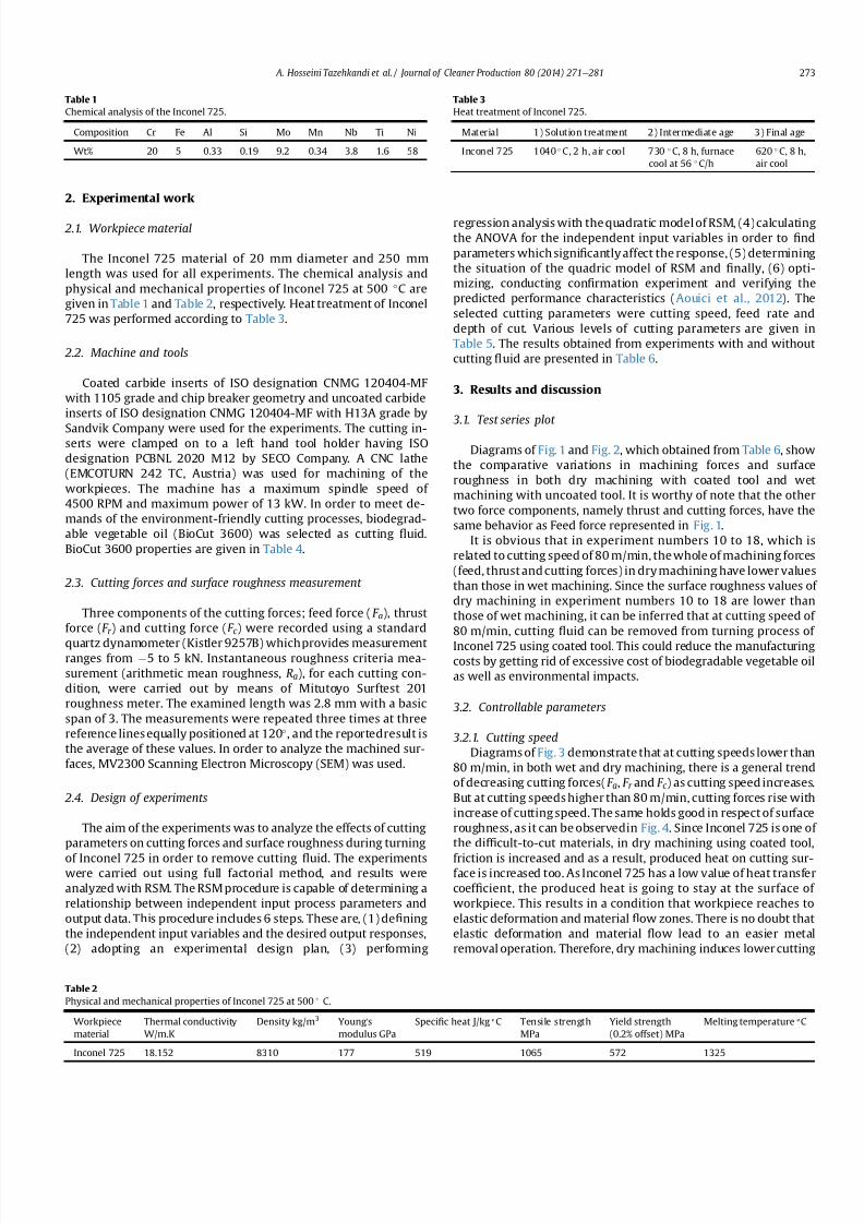
7212019 Journal of Cleaner ProductionExperimental Investigation On
httpslidepdfcomreaderfulljournal-of-cleaner-productionexperimental-investigation-on 311
2 Experimental work
21 Workpiece material
The Inconel 725 material of 20 mm diameter and 250 mm
length was used for all experiments The chemical analysis and
physical and mechanical properties of Inconel 725 at 500 C are
given in Table 1 and Table 2 respectively Heat treatment of Inconel
725 was performed according to Table 3
22 Machine and tools
Coated carbide inserts of ISO designation CNMG 120404-MF
with 1105 grade and chip breaker geometry and uncoated carbide
inserts of ISO designation CNMG 120404-MF with H13A grade by
Sandvik Company were used for the experiments The cutting in-serts were clamped on to a left hand tool holder having ISO
designation PCBNL 2020 M12 by SECO Company A CNC lathe
(EMCOTURN 242 TC Austria) was used for machining of the
workpieces The machine has a maximum spindle speed of
4500 RPM and maximum power of 13 kW In order to meet de-
mands of the environment-friendly cutting processes biodegrad-
able vegetable oil (BioCut 3600) was selected as cutting 1047298uid
BioCut 3600 properties are given in Table 4
23 Cutting forces and surface roughness measurement
Three components of the cutting forces feed force (F a) thrust
force (F r ) and cutting force (F c ) were recorded using a standard
quartz dynamometer (Kistler 9257B) which provides measurementranges from 5 to 5 kN Instantaneous roughness criteria mea-
surement (arithmetic mean roughness Ra) for each cutting con-
dition were carried out by means of Mitutoyo Surftest 201
roughness meter The examined length was 28 mm with a basic
span of 3 The measurements were repeated three times at three
reference lines equally positioned at 120 and the reportedresult is
the average of these values In order to analyze the machined sur-
faces MV2300 Scanning Electron Microscopy (SEM) was used
24 Design of experiments
The aim of the experiments was to analyze the effects of cutting
parameters on cutting forces and surface roughness during turning
of Inconel 725 in order to remove cutting 1047298uid The experimentswere carried out using full factorial method and results were
analyzed with RSM The RSM procedure is capable of determining a
relationship between independent input process parameters and
output data This procedure includes 6 steps These are (1) de1047297ning
the independent input variables and the desired output responses
(2) adopting an experimental design plan (3) performing
regression analysis with the quadratic model of RSM (4) calculating
the ANOVA for the independent input variables in order to 1047297nd
parameters which signi1047297cantly affect the response (5) determining
the situation of the quadric model of RSM and 1047297nally (6) opti-
mizing conducting con1047297rmation experiment and verifying the
predicted performance characteristics (Aouici et al 2012) The
selected cutting parameters were cutting speed feed rate and
depth of cut Various levels of cutting parameters are given in
Table 5 The results obtained from experiments with and without
cutting 1047298uid are presented in Table 6
3 Results and discussion
31 Test series plot
Diagrams of Fig 1 and Fig 2 which obtained from Table 6 show
the comparative variations in machining forces and surface
roughness in both dry machining with coated tool and wet
machining with uncoated tool It is worthy of note that the other
two force components namely thrust and cutting forces have the
same behavior as Feed force represented in Fig 1
It is obvious that in experiment numbers 10 to 18 which is
related to cutting speed of 80 mmin the whole of machining forces
(feed thrust and cutting forces) in dry machining have lower values
than those in wet machining Since the surface roughness values of
dry machining in experiment numbers 10 to 18 are lower than
those of wet machining it can be inferred that at cutting speed of
80 mmin cutting 1047298uid can be removed from turning process of
Inconel 725 using coated tool This could reduce the manufacturingcosts by getting rid of excessive cost of biodegradable vegetable oil
as well as environmental impacts
32 Controllable parameters
321 Cutting speed
Diagrams of Fig 3 demonstrate that at cutting speeds lower than
80 mmin in both wet and dry machining there is a general trend
of decreasing cutting forces(F a F r and F c ) as cutting speed increases
But at cutting speeds higher than 80 mmin cutting forces rise with
increase of cutting speed The same holds good in respect of surface
roughness as it can be observedin Fig 4 Since Inconel 725 is one of
the dif 1047297cult-to-cut materials in dry machining using coated tool
friction is increased and as a result produced heat on cutting sur-face is increased too As Inconel 725 has a low value of heat transfer
coef 1047297cient the produced heat is going to stay at the surface of
workpiece This results in a condition that workpiece reaches to
elastic deformation and material 1047298ow zones There is no doubt that
elastic deformation and material 1047298ow lead to an easier metal
removal operation Therefore dry machining induces lower cutting
Table 1
Chemical analysis of the Inconel 725
Composition Cr Fe Al Si Mo Mn Nb Ti Ni
Wt 20 5 033 019 92 034 38 16 58
Table 2
Physical and mechanical properties of Inconel 725 at 500 C
Workpiece
material
Thermal conductivity
WmK
Density kgm3 Youngs
modulus GPa
Speci1047297c heat Jkg ordmC Tensile strength
MPa
Yield strength
(02 offset) MPa
Melting temperature ordmC
Inconel 725 18152 8310 177 519 1065 572 1325
Table 3
Heat treatment of Inconel 725
Material 1) Solution treatment 2) Intermediate age 3) Final age
Inconel 725 1040 C 2 h air cool 730 C 8 h furnace
cool at 56 Ch
620 C 8 h
air cool
A Hosseini Tazehkandi et al Journal of Cleaner Production 80 (2014) 271e 281 273
7212019 Journal of Cleaner ProductionExperimental Investigation On
httpslidepdfcomreaderfulljournal-of-cleaner-productionexperimental-investigation-on 411
forces as well as better surface 1047297nish It is worth noting that a
coated tool was used in order to decline friction on cuttingarea andprevent the surface of workpiece from reaching to plastic defor-
mation zone In contrast to dry machining in machining using
cutting 1047298uids when cutting speed is increased part of produced
heat on workpiece surface go away and the softening effect of heat
Table 4
Properties of biodegradable vegetable oil (BioCut 3600)
Cutting 1047298uid ISO grade Speci1047297c gravity Viscosity index Pour point Flash point Coppe r corrosion Biodegradability
BioCut 3600 36 0913 150 18 C 260 C Pass gt95
Table 5
Various levels of machining parameters
Symbo l Machi ni ng par ameters U ni t Level 1 Level 2 L evel 3
A Cutting Speed mmin 60 80 100
B Feed rate mmrev 01 015 020
C Depth of cut mm 040 080 120
Table 6
The results of the turning tests on Inconel 725 with and without cutting 1047298uid
Tests Cutting speed
(mmin)
Feed rate
(mmrev)
Depth of cut
(mm)
F a (N) wet
uncoated
F a (N) dry
coated
F r (N) wet
uncoated
F r (N) dry
coated
F c (N) wet
uncoated
F c (N) dry
coated
Ra (mm) wet
uncoated
Ra(mm) dry
coated
01 60 010 04 199 227 314 372 521 612 074 086
02 60 010 08 261 291 397 455 654 744 074 087
03 60 010 12 331 361 476 535 811 901 072 089
04 60 015 04 202 232 325 383 607 697 098 110
05 60 015 08 250 280 410 468 672 762 100 112
06 60 015 12 357 387 510 568 833 922 101 113
07 60 020 04 223 253 369 427 564 654 113 125
08 60 020 08 298 328 447 505 722 812 111 128
09 60 020 12 391 421 617 675 913 1003 109 127
10 80 010 04 155 154 254 252 389 389 056 052
11 80 010 08 227 225 355 354 582 580 056 056
12 80 010 12 336 331 495 495 706 704 053 053
13 80 015 04 161 159 255 253 464 460 072 070
14 80 015 08 235 230 364 359 573 568 075 073
15 80 015 12 344 338 509 491 729 710 078 075
16 80 020 04 185 180 292 282 474 459 083 080
17 80 020 08 267 256 416 400 593 581 085 082
18 80 020 12 383 375 604 592 859 839 084 081
19 100 010 04 174 204 265 323 502 592 060 072
20 100 010 08 238 268 361 419 564 654 061 073
21 100 010 12 321 351 470 528 744 834 062 074
22 100 015 04 172 202 259 317 459 549 078 09023 100 015 08 248 278 363 421 571 661 082 094
24 100 015 12 327 357 465 530 752 842 080 092
25 100 020 04 191 221 306 364 511 601 091 103
26 100 020 08 287 317 473 531 640 730 092 104
27 100 020 12 378 408 621 679 848 938 092 105
Fig 1 Test series plot diagram of Feed force in machining with and without cutting
1047298uid
Fig 2 Test series plot diagram of Surface roughness in machining with and without
cutting 1047298
uid
A Hosseini Tazehkandi et al Journal of Cleaner Production 80 (2014) 271e 281274
7212019 Journal of Cleaner ProductionExperimental Investigation On
httpslidepdfcomreaderfulljournal-of-cleaner-productionexperimental-investigation-on 511
7212019 Journal of Cleaner ProductionExperimental Investigation On
httpslidepdfcomreaderfulljournal-of-cleaner-productionexperimental-investigation-on 611
fact that an increase in feed rate results in formation of built e up e
edge by virtue of cold weld that take place between some pieces of
produced chips and cutting edge of tool Formation of built e up e
edge makes grooves on workpiece surface and this in turn not only
damages the surface of workpiece but also extremely increases the
cutting forces In dry machining with coated tool the coating of tool
can postpone formation of built e up e edge up to a point It can
abate the increasing trend of cutting forces and surface roughness
However in machining with uncoated tool high probability of
formation of built e up e edge induces higher cutting forces and
surface roughness (Settineri et al 2008) Considering the results
that are presented in Table 6 it can be observed that in machining
with cutting speed of 80 mmin even an increase in feed ratewould
result in lower values of cutting forces and surface roughness
compare with those achieved in wet machining Therefore at cut-ting speed of 80 mmin it is possible to remove the cutting 1047298uid
from turning process with any feed rate Fig 9 and Fig10 show SEMimages of workpiece surface in processing with cutting speed of
80 mmin feed rate of 02 mm and depth of cut of 04 mmrev in
wet and dry machining respectively By comparison with Fig 9
which is related to wet machining image of workpiece surface in
dry machining (Fig 10) has less grooves and hence has better
surface 1047297nish It is known that dry machining using excessive feed
rates causes signi1047297cant damages to coating of tool and on the other
hand since there is not any cutting 1047298uid in dry machining the
produced chips are willing to remain at surface of workpiece
Because of these two reasons built e up e edge was formed and
would be hardened during the turning process and therefore in-
duces deep grooves on workpiece surface with plastic deformations
on the edges of these grooves This can noticeably affect the me-
chanical properties of workpiece In some cases hardened built e
up e edge may break some parts of workpiece material and induces
various type of wear mechanisms so it is impossible to remove the
Fig 6 SEM image of Inconel 725 surface machined in dry condition using coated tool
in cutting speed of 80 mmin feed rate of 01 mmrev depth of cut of 04 mm
Fig 7 Effect of feed rate on cutting forces in dry and wet machining
Fig 8 Effect of feed rate on surface roughness in both dry and wet machining
A Hosseini Tazehkandi et al Journal of Cleaner Production 80 (2014) 271e 281276
7212019 Journal of Cleaner ProductionExperimental Investigation On
httpslidepdfcomreaderfulljournal-of-cleaner-productionexperimental-investigation-on 711
cutting1047298
uid On the other hand selecting very low levels of cuttingspeeds is not productive because of increase in special cutting en-
ergy consumption power of machine and machining time In other
words with the increase in consumption power of machine and
machining time the utilization of cutting 1047298uid and machining costs
considerably grow and tool and workpiece are exposed to higher
temperatures for a long period
Taking all above-mentioned discussion into consideration it can
be concluded that in selection of feed rate for purpose of removing
cutting 1047298uid it is very important to choose the appropriate ranges
of this parameter
323 Depth of cut
According to Fig 11 in both wet and dry machining an increase
in depth of cut results in increased cutting forces and Fig12 clearlyreveals that as cutting forces increase so does the surface rough-
ness of workpiece surface When the cutting speed of machining is
80 mmin increasing depth of cut induces higher material
removing rate Also tool coating plays an important role in
Fig 9 SEM image of workpiece surface in processing with cutting speed of 80 mmin
feed rate of02 mmand depthof cutof 04mmrevin wetmachiningwithuncoatedtool
Fig 10 SEM image of workpiece surface in processing with cutting speed of 80 mmin
feed rate of 02 mm and depth of cut of 04 mmrev in dry machining with coated tool
Fig 11 Effect of depth of cut variations on cutting forces in dry and wet machining
Fig 12 Effect of depth of cut variations on surface roughness in both dry and wet
machining
A Hosseini Tazehkandi et al Journal of Cleaner Production 80 (2014) 271e 281 277
7212019 Journal of Cleaner ProductionExperimental Investigation On
httpslidepdfcomreaderfulljournal-of-cleaner-productionexperimental-investigation-on 811
reducing friction between tool cutting edge and produced chips
which can retard the extreme growth of produced heat So higher
amount of depth of cut results in higher cutting forces However in
wet machining using uncoated tool as depth of cut increases
produced heat on surface of workpiece increases too It is known
that Inconel 725 has lower amount of heat transfer coef 1047297cient and
on the other hand cutting 1047298uid can only transfer a small part of
produced heat Therefore excessive heat on cutting surface in
combination with higher material removing rate would raise cut-
ting forces and deteriorate surface 1047297nish Finally increasing trend
of cutting forces in wet machining would be much more noticeable
than that of dry machining It can be concluded that in machining
with cutting speed of 80 mmin even in higher amount of depth of
cut it is possible to remove cutting 1047298uid from the process One
interesting point is that in dry machining with coated tool depth of
cut should not take values lower than radius of tool corner
(04 mm) otherwise cutting operation will be carried out through
tool corner instead of cutting edge In this condition ploughing
phenomenon can cause severe growth in cutting forces and dete-
rioration in surface 1047297nish (Ulutan and Ozel 2011) Fig 13 clearly
reveals how ploughing phenomenon can completely damage the
surface 1047297nish of workpiece
33 Analysis of variance (ANOVA)
The ANOVA method measures the effect of input variables on
response variables through the relationship between these three
sets of variables The purpose of ANOVA is to determine which
machining parameters highly affect the cutting forces and surface
roughness (Camposeco-Negrete 2013) The statistical signi1047297cance
of the 1047297tted quadratic models was evaluated by the P -values of the
ANOVA These values are given in Table 7 (for feed force-Dry)
Table 8 (for thrust force-Dry) Table 9 (for cutting force-Dry)
Table 10 (for surface roughness-Dry) Table 11 (for feed force-
Wet) Table 12 (for thrust force-Wet) Table 13 (for cutting force-
Wet) and Table 14 (for surface roughness-Wet) When P -valuesare less than 005 (or 95 con1047297dence) the obtained models are
considered to be statistically signi1047297cant It demonstrates that the
chosen parameters in model have signi1047297cant effect on the re-
sponses The F-value is an index used to check the adequacy of the
model (Bouacha et al 2010) In both dry and wet machining of
Inconel 725 cutting speed has remarkable effect on feed force andcutting force However cutting speed and cutting force are in order
of the most effective parameters on thrust force In the case of
Table 7
Analysis of variance for feed force (N) e in dry machining with coated tool
Term DOF Seq SS Adj SS Adj MS F P
Regression 9 149704 149704 166338 13652 0000
linear 3 131269 16313 54376 4463 0000
A 1 1682 16127 16127 13236 0000
B 1 6689 219 2187 180 0198
C 1 122897 17 168 014 0715
A2
1 16098 16481 4814 13527 0000B2 1 475 337 3371 277 0115
C2 1 736 821 8211 674 0019
AB 1 0 0 0 000 1000
AC 1 421 421 4213 346 0040
BC 1 705 705 7053 579 0028
Error 17 2071 2071 1218
Total 26 151775
R-Sq 9632
DOF frac14 Degree Of Freedom SS frac14 Sum of Squares MS or MSD frac14 Mean Square F frac14 F -
value P frac14 P -value
Dry frac14 dry machining with coated tool
Wet frac14 machining with cutting 1047298uid and uncoated tool
Table 8
Analysis of variance for thrust force (N) e in dry machining with coated tool
Term DOF Seq SS Adj SS Adj MS F P
Regression 9 344329 344329 382587 11974 0000
linear 3 281721 53015 176716 5531 0000
A 1 4232 51343 513427 16069 0000
B 1 28960 3780 37796 1183 0003
C 1 248529 1136 11362 356 0077
A2 1 47661 48797 487973 15273 0000
B2 1 4397 3628 36279 1135 0004
C2 1 1148 1471 14707 460 0047
AB 1 290 290 2901 091 0354AC 1 3391 3391 33909 1061 0005
BC 1 5720 5720 57203 1790 0001
Error 17 5432 5432 3195
Total 26 349760
R-Sq 9570
DOF frac14 Degree Of Freedom SS frac14 Sum of Squares MS or MSD frac14 Mean Square F frac14 F -
value P frac14 P -value
Dry frac14 dry machining with coated tool
Wet frac14 machining with cutting 1047298uid and uncoated tool
Table 9
Analysis of variance for cutting force (N) e in dry machining with coated tool
Term DOF Seq SS Adj SS Adj MS F P
Regression 9 63145 613145 68127 6600 0000
linear 3 436807 163532 54511 5281 0000
A 1 27691 161302 161302 1 5627 0 000
B 1 20469 68 68 007 0800
C 1 388647 321 321 031 0584
A2 1 167056 169420 57389 16413 0000
B2 1 329 127 127 012 0730
C2 1 4349 4563 4563 442 0051
AB 1 44 44 44 004 0839
AC 1 526 526 526 051 0485
BC 1 4033 4033 4033 391 0065
Error 17 17548 17548 1032
Total 26 630693
R-Sq 9352
DOF frac14 Degree Of Freedom SS frac14 Sum of Squares MS or MSD frac14 Mean Square F frac14 F -
value P frac14 P -value
Dry frac14 dry machining with coated tool
Wetfrac14
machining with cutting 1047298
uid and uncoated tool
Fig 13 SEM image surface of Inconel 725 in dry machining with cutting speed of
80 mmin feed rate of 02 mm and depth of cut of 01 mm for showing ploughing
phenomenon
A Hosseini Tazehkandi et al Journal of Cleaner Production 80 (2014) 271e 281278
7212019 Journal of Cleaner ProductionExperimental Investigation On
httpslidepdfcomreaderfulljournal-of-cleaner-productionexperimental-investigation-on 911
surface 1047297nish these parameters are cutting and feed force The
effectiveness of the models for feed force thrust force cutting force
and surface roughness can be further analyzed with help of the R-
Sq values A higher value of R-Sq is always desirable
34 Regression equations
The relationship between the factors and performance mea-surements were modeled by quartic regression Using these
equations it is possible to achieve the values of machining force
components and surface roughness in both wet and dry conditions
It should be noted that the amount of input parameters needs to be
within the selected ranges As it is presented in ANOVA
Tables 7e14 the parameters with P values less than 005 have less
impact on results of experiments However in order to achieve the
maximum precision and minimum possible error in regression
models 1 to 8 even effect of the less effective machining parame-
ters and counter-effect of them have been taken into account The
cutting parameters of cutting speed feed rate and depth of cut are
represented by symbols of A B and C respectively The obtained
regression equations were as follows
Thefeed force in drymachining model (F a)isgivenbelowinEq (1)
F afrac1410846219Athorn01A2thorn737C2
thorn07ACthorn3833BC (1)
The thrust force in dry machining model (F r ) is given by Eq (2)
F r frac14 2099 391A 3431B thorn 02A2thorn 98893B2
thorn 987C2
thorn 22ACthorn 10916BC (2)
The cutting force model in dry machining (F c ) is given by Eq (3)
Table 10
Analysisof Variance for Surface roughness(mm) ein dry machining withcoated tool
Term DOF Seq SS Adj SS Adj MS F P
Regression 9 119808 116808 0133120 27633 0000
linear 3 063877 057267 0190890 39625 0000
A 1 016056 049409 0494090 102564 0000
B 1 047694 003425 0034255 7111 0000
C 1 000128 000066 0000657 136 0259
A2
1 054101 053815 0538149 11171 0000B2 1 001251 001190 0011905 2471 0000
C2 1 000056 000057 0000566 118 0293
AB 1 000521 000521 0005208 1081 0004
AC 1 000002 000002 0000015 003 00861
BC 1 000001 000001 0000008 002 0897
Error 17 000819 000819 0000482
Total 26 120627
R-Sq 9832
DOF frac14 Degree Of Freedom SS frac14 Sum of Squares MS or MSD frac14 Mean Square F frac14 F -
value P frac14 P -value
Dry frac14 dry machining with coated tool
Wet frac14 machining with cutting 1047298uid and uncoated tool
Table 11
Analysis of variance for feed force (N) e in wet machining with uncoated tool
Term DOF Seq SS Adj SS Adj MS F P
Regression 9 138468 138468 15385 12069 0000
linear 3 134374 2302 7673 602 0005
A 1 1721 2163 2163 1697 0001
B 1 7240 248 2479 194 0181
C 1 125413 14 135 011 0749
A2 1 1719 1853 1853 787 0001
B2 1 520 377 377 296 0104
C2 1 687 772 772 606 0025
AB 1 0 0 03 000 0960
AC 1 447 447 4466 350 0079
BC 1 721 721 7207 565 0029
Error 17 2167 2167 1275
Total 26 140635
R-Sq 9573
DOF frac14 Degree Of Freedom SS frac14 Sum of Squares MS or MSD frac14 Mean Square F frac14 F -value P frac14 P -value
Dry frac14 dry machining with coated tool
Wet frac14 machining with cutting 1047298uid and uncoated tool
Table 12
Analysis of variance for thrust force (N) e in wet machining with uncoated tool
Term DOF Seq SS Adj SS Adj MS F P
Regression 9 308682 308682 34298 13107 0000
linear 3 290198 9127 30422 1163 0000
A 1 4418 5515 55152 2108 0000
B 1 31920 3758 37577 1436 0001
C 1 253860 1174 11738 449 0049
A2 1 3278 3608 36078 1379 0002
B2 1 4458 3677 36772 1405 0002
C2 1 1212 1539 15391 588 0027
AB 1 280 280 2803 107 0315
AC 1 3314 3314 33142 1267 0002
BC 1 5941 5941 59407 2270 0000
Error 17 4448 4448 2617
Total 26 313131
R-Sq 9598
DOF frac14 Degree Of Freedom SS frac14 Sum of Squares MS or MSD frac14 Mean Square F frac14 F -
value P frac14 P -value
Dry frac14 dry machining with coated tool
Wetfrac14
machining with cutting 1047298
uid and uncoated tool
Table 13
Analysis of variance for cutting force (N) e in wet machining with uncoated tool
Term DOF Seq SS Adj SS Adj MS F P
Regression 9 489771 489771 54419 5245 0000
linear 3 452132 30067 100223 966 0001
A 1 28691 29954 299538 2887 0000
B 1 23545 36 361 003 0854
C 1 400897 401 4007 039 0543
A2
1 27855 28876 289763 2793 0000B2 1 284 95 945 009 0766
C2 1 4817 5040 50402 486 0042
AB 1 48 4684 15612 005 0832
AC 1 529 48 480 051 0485
BC 1 4107 529 5285 396 0063
Error 17 17638 4107 41070
Total 26 507409 17638 10375
R-Sq 9173
DOF frac14 Degree Of Freedom SS frac14 Sum of Squares MS or MSD frac14 Mean Square F frac14 F -
value P frac14 P -value
Dry frac14 dry machining with coated tool
Wet frac14 machining with cutting 1047298uid and uncoated tool
Table 14
Analysis of variance for surface roughness (mm) e in wet machining with uncoated
tool
Term DOF Seq SS Adj SS Adj MS F P
Regression 9 0759871 0759871 0084430 17641 0000
linear 3 0605476 0185149 0061716 12895 0000
A 1 0131756 0126925 0126925 26521 0000
B 1 0473689 0040946 0040946 8555 0000
C 1 0000031 0000004 0000004 001 0930
A2 1 0131131 0130791 0130791 27328 0000
B2 1 0018641 0018406 0018406 3846 0000
C2 1 0000291 0000225 0000225 047 0502
AB 1 0003675 0003675 0003675 768 0013
AC 1 0000649 0000649 0000649 136 0260
BC 1 00000080 0000008 0000008 002 0897
Error 17 0008136 0008136 0000479
Total 26 0768007
R-Sq 9825
DOF frac14 Degree Of Freedom SS frac14 Sum of Squares MS or MSD frac14 Mean Square F frac14 F -
value P frac14 P -value
Dry frac14 dry machining with coated tool
Wetfrac14
machining with cutting 1047298
uid and uncoated tool
A Hosseini Tazehkandi et al Journal of Cleaner Production 80 (2014) 271e 281 279
7212019 Journal of Cleaner ProductionExperimental Investigation On
httpslidepdfcomreaderfulljournal-of-cleaner-productionexperimental-investigation-on 1011
F c frac14 32808 694Athorn 04A2thorn 1738C2 (3)
The surface roughness model in dry machining (Ra) is given by
Eq (4)
Ra frac14 47 01Athorn 103Bthorn 00007A2 179B2
002AB (4)
The feed force in wet machining model (F a) is given below in Eq
(5)
F a frac14 5349 81Athorn 004A2thorn 715C2
thorn 3875BC (5)
The thrust force in wet machining model (F r ) is given by Eq (6)
F r frac14 10508 128A 342B 195C thorn 006A2thorn 9956B2
thorn 101C2thorn 22ACthorn 11125BC (6)
The cutting force model in wet machining (F c ) is given byEq (7)
F c frac14 1699 30Athorn 02A2thorn 1826C2 (7)
The surface roughness model in wet machining (Ra) is given by
Eq (8)
Ra frac14 23 006Athorn 113Bthorn 00004A2 22B2 002AB (8)
35 Optimization of cutting conditions
It was assumed that the optimal manufacturing conditions for
turning of Inconel 725 without cutting 1047298uid are those with mini-
mum values of cutting forces (F a F r and F c ) and surface roughness
(Ra) during the turning process It is worth noting that although
main aim of this research is removing cutting 1047298uid from machining
process some operating condition make it mandatory to utilize
cutting 1047298uid So additional study has been presented to optimizing
consumption of cutting 1047298uid during wet machining of Inconel 725
The objective of optimizing the turning process of Inconel 725
with and without cutting 1047298uid is to achieve the minimum possiblelevel of machining force components and maximum level of surface
1047297nish Therefore the optimization has been carried out with taking
the attainment of minimum cutting feed and thrust forces and
maximum surface 1047297nish into account The experiments are also
conducted practically using the provided numbers for the param-
eters A (cutting speed) B (feed rate) and C (depth of cut) in both dry
and wet machining conditions by Minitab software in order to
demonstrate the differences between the values of predicted re-
sponses and the experimental values The results of RSM procedure
have been validated using the output of experiments and it was
con1047297rmed that value of error in RSM method in dry and wet con-
ditions is less than 5 percent Table 15 and Table 16 show the RSM
optimization results for cutting forces and surface roughness in dry
and wet machining
4 Conclusion
In this study effects of process parameters (which include
cutting speed feed rate and depth of cut) and tool coating on
machining forces and surface roughness were investigated in both
dry and wet machining of nickel-based superalloy Inconel 725 in
order to remove the cutting 1047298uid and meet environmental de-
mands Considering environmental problems Biodegradablevegetable oil was utilized as cutting 1047298uid in wet machining All
experiments were carried out in full factorial method and they
were analyzed using RSM and ANOVA methods Finally optimized
parameters were achieved for both dry and wet machining The
foremost conclusions which can be drawn are as follows
Removal of cutting 1047298uid in the above-mentioned conditions
result in reduced production costs and 1047298uid production ex-
penses This in turn reduces costs of removing it from the ma-
chine and the parts and eliminates destructive effect of these
1047298uids on the environment and human health
The role of tool coating in reduction of cutting forces and
improving surface 1047297nish is much more effective than using
cutting 1047298uid Since Inconel 725 is one of the dif 1047297cult-to-cut
materials excessive heat was produced during turning and
remained on workpiece surface due to low heat transfer ca-
pacity of cutting 1047298uid However coating of tool reduced friction
and as a result made it possible to remove the cutting 1047298uid
When Inconel 725 was machined with cutting speed of 80 m
min regardless of the values of feed rate and depth of cut it was
quite feasible to eliminated cutting 1047298uid from turning process
In order to reach to the aim of successfully removing cutting
1047298uids from wet and dry machining cutting speed should not
exceed 80 mmin because it induced higher cutting forces and
deteriorated surface 1047297nish
Excessive increase of cutting speed could damage tool coating
and make it practically impossible to remove cutting 1047298uid
There was a general trend of increasing cutting forces and sur-
face roughness as feed rate and depth of cut increase
References
Aouici H Yallese MA Chaoui K Mabrouki T Rigal J-F 2012 Analysis of sur-face roughness and cutting force components in hard turning with CBN toolprediction model and cutting conditions optimization Measurement 45344e353
Bouacha K Yallese MA Mabrouki T Rigal J-F 2010 Statistical analysis of sur-face roughness and cutting forces using response surface methodology in hardturning of AISI 52100 bearing steel with CBN tool Int J Refract Metals HardMater 28 349e361
Camposeco-Negrete C 2013 Optimization of cutting parameters for minimizingenergy consumption in turning of AISI 6061 T6 using Taguchi methodology andANOVA J Clean Prod 53 195e203
Davim JP 2013 Green Manufacturing Processes and Systems Springer London
UK
Table 15
The improved values for dry machining of Inconel 725
Cutting speed
(mmin)
Feed rate
(mmrev)
Depth of
cut (mm)
Feed force (N) Thrust force (N) Cutting force (N) Surface roughness
(mm)
Error
Predicted values 822 01 04 15834 25727 42801 0492 5
Experimental values 822 01 04 16413 26922 44179 051 e
Table 16
The improved values for wet machining of Inconel 725
Cutting speed
(mmin)
Feed rate
(mmrev)
Depth of
cut (mm)
Feed force (N) Thrust force (N) Cutting force (N) Surface roughness
(mm)
Error
Predicted values 896 01 04 1604 2567 43045 051 5
Experimental values 896 01 04 16729 2669 45240 054 e
A Hosseini Tazehkandi et al Journal of Cleaner Production 80 (2014) 271e 281280
7212019 Journal of Cleaner ProductionExperimental Investigation On
httpslidepdfcomreaderfulljournal-of-cleaner-productionexperimental-investigation-on 1111
Davoodi B Tazehkandi AH 2014 Experimental investigation and optimization of cutting parameters in dry and wet machining of aluminum alloy 5083 in orderto remove cutting 1047298uid J Clean Prod 68 234e242 httpdxdoiorg101016
jjclepro201312056Devillez A Le Coz G Dominiak S Dudzinski D 2011 Dry machining of Inconel
718 workpiece surface integrity J Mater Process Technol 211 1590e1598Ezilarasan C Velayudham A January 2013 An experimental analysis and
measurement of process performances in machining of nimonic C-263super alloy Measurement 46 (1) 185e199 httpdxdoiorg101016
jmeasurement201206006
Fratila D Caizar C 2011 Application of Taguchi method to selection of optimallubrication and cutting conditions in face milling of AlMg 3 J Clean Prod 19640e645
Groover MP 2007 Fundamentals of Modern Manufacturing Materials Processesand Systems Wiley com United States of America
Kuram E Ozcelik B Bayramoglu M Demirbas E Simsek BT 2012 Optimizationof cutting 1047298uids and cutting parameters during end milling by using D-optimaldesign of experiments J Clean Prod
Kuram E Ozcelik B Demirbas E 2013 Environmentally Friendly MachiningVegetable Based Cutting Fluids Green Manufacturing Processes and SystemsSpringer pp 23e47
Lalwani D Mehta N Jain P 2008 Experimental investigations of cutting pa-rameters in1047298uence on cutting forces and surface roughness in 1047297nish hardturning of MDN250 steel J Mater Process Technol 206 167e179
Lawal SA Choudhury IA Nukman Y 2013 A critical assessment of lubricationtechniques in machining processes a case for minimum quantity lubricationusing vegetable oil-based lubricant J Clean Prod 41 210e221
Mandal N Doloi B Mondal B Das R 2011 Optimization of 1047298ank wear usingZirconia Toughened Alumina (ZTA) cutting tool Taguchi method and Regres-sion analysis Measurement 44 2149e2155
Nalbant M Altın A Geurookkaya H 2007 The effect of cutting speed and cutting toolgeometry on machinability properties of nickel-base Inconel 718 super alloysMater Des 28 1334e1338
Sarıkaya M Guumllluuml A 2014 Taguchi design and response surface methodology
based analysis of machining parameters in CNC turning under MQL J CleanProd 65 604e616
Settineri L Faga MG Lerga B 2008 Properties and performances of innovativecoated tools for turning inconel Int J Mach Tools Manuf 48 815e823
Ulutan D Ozel T 2011 Machining induced surface integrity in titanium and nickelalloys a review Int J Mach Tools Manuf 51 250e280
Weinert K Inasaki I Sutherland J Wakabayashi T 2004 Dry machining andminimum quantity lubrication CIRP Ann Manuf Techn 53 511e537
Zhang S Li J Wang Y 2012 Tool life and cutting forces in end milling Inconel 718under dry and minimum quantity cooling lubrication cutting conditions
J Clean Prod 32 81e87ZouB ChenM Huang CAnQ 2009 Studyon surface damages causedby turning
NiCr20TiAl nickel-based alloy J Mater Process Technol 209 5802e5809
A Hosseini Tazehkandi et al Journal of Cleaner Production 80 (2014) 271e 281 281
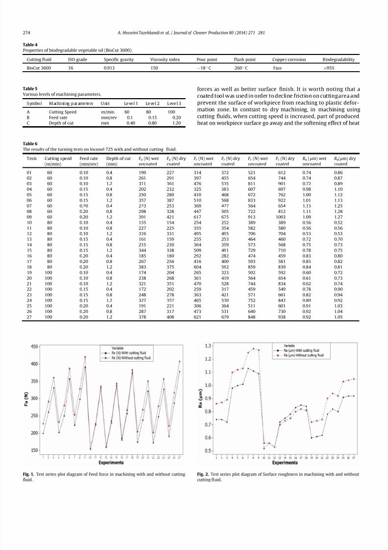
7212019 Journal of Cleaner ProductionExperimental Investigation On
httpslidepdfcomreaderfulljournal-of-cleaner-productionexperimental-investigation-on 411
forces as well as better surface 1047297nish It is worth noting that a
coated tool was used in order to decline friction on cuttingarea andprevent the surface of workpiece from reaching to plastic defor-
mation zone In contrast to dry machining in machining using
cutting 1047298uids when cutting speed is increased part of produced
heat on workpiece surface go away and the softening effect of heat
Table 4
Properties of biodegradable vegetable oil (BioCut 3600)
Cutting 1047298uid ISO grade Speci1047297c gravity Viscosity index Pour point Flash point Coppe r corrosion Biodegradability
BioCut 3600 36 0913 150 18 C 260 C Pass gt95
Table 5
Various levels of machining parameters
Symbo l Machi ni ng par ameters U ni t Level 1 Level 2 L evel 3
A Cutting Speed mmin 60 80 100
B Feed rate mmrev 01 015 020
C Depth of cut mm 040 080 120
Table 6
The results of the turning tests on Inconel 725 with and without cutting 1047298uid
Tests Cutting speed
(mmin)
Feed rate
(mmrev)
Depth of cut
(mm)
F a (N) wet
uncoated
F a (N) dry
coated
F r (N) wet
uncoated
F r (N) dry
coated
F c (N) wet
uncoated
F c (N) dry
coated
Ra (mm) wet
uncoated
Ra(mm) dry
coated
01 60 010 04 199 227 314 372 521 612 074 086
02 60 010 08 261 291 397 455 654 744 074 087
03 60 010 12 331 361 476 535 811 901 072 089
04 60 015 04 202 232 325 383 607 697 098 110
05 60 015 08 250 280 410 468 672 762 100 112
06 60 015 12 357 387 510 568 833 922 101 113
07 60 020 04 223 253 369 427 564 654 113 125
08 60 020 08 298 328 447 505 722 812 111 128
09 60 020 12 391 421 617 675 913 1003 109 127
10 80 010 04 155 154 254 252 389 389 056 052
11 80 010 08 227 225 355 354 582 580 056 056
12 80 010 12 336 331 495 495 706 704 053 053
13 80 015 04 161 159 255 253 464 460 072 070
14 80 015 08 235 230 364 359 573 568 075 073
15 80 015 12 344 338 509 491 729 710 078 075
16 80 020 04 185 180 292 282 474 459 083 080
17 80 020 08 267 256 416 400 593 581 085 082
18 80 020 12 383 375 604 592 859 839 084 081
19 100 010 04 174 204 265 323 502 592 060 072
20 100 010 08 238 268 361 419 564 654 061 073
21 100 010 12 321 351 470 528 744 834 062 074
22 100 015 04 172 202 259 317 459 549 078 09023 100 015 08 248 278 363 421 571 661 082 094
24 100 015 12 327 357 465 530 752 842 080 092
25 100 020 04 191 221 306 364 511 601 091 103
26 100 020 08 287 317 473 531 640 730 092 104
27 100 020 12 378 408 621 679 848 938 092 105
Fig 1 Test series plot diagram of Feed force in machining with and without cutting
1047298uid
Fig 2 Test series plot diagram of Surface roughness in machining with and without
cutting 1047298
uid
A Hosseini Tazehkandi et al Journal of Cleaner Production 80 (2014) 271e 281274
7212019 Journal of Cleaner ProductionExperimental Investigation On
httpslidepdfcomreaderfulljournal-of-cleaner-productionexperimental-investigation-on 511
7212019 Journal of Cleaner ProductionExperimental Investigation On
httpslidepdfcomreaderfulljournal-of-cleaner-productionexperimental-investigation-on 611
fact that an increase in feed rate results in formation of built e up e
edge by virtue of cold weld that take place between some pieces of
produced chips and cutting edge of tool Formation of built e up e
edge makes grooves on workpiece surface and this in turn not only
damages the surface of workpiece but also extremely increases the
cutting forces In dry machining with coated tool the coating of tool
can postpone formation of built e up e edge up to a point It can
abate the increasing trend of cutting forces and surface roughness
However in machining with uncoated tool high probability of
formation of built e up e edge induces higher cutting forces and
surface roughness (Settineri et al 2008) Considering the results
that are presented in Table 6 it can be observed that in machining
with cutting speed of 80 mmin even an increase in feed ratewould
result in lower values of cutting forces and surface roughness
compare with those achieved in wet machining Therefore at cut-ting speed of 80 mmin it is possible to remove the cutting 1047298uid
from turning process with any feed rate Fig 9 and Fig10 show SEMimages of workpiece surface in processing with cutting speed of
80 mmin feed rate of 02 mm and depth of cut of 04 mmrev in
wet and dry machining respectively By comparison with Fig 9
which is related to wet machining image of workpiece surface in
dry machining (Fig 10) has less grooves and hence has better
surface 1047297nish It is known that dry machining using excessive feed
rates causes signi1047297cant damages to coating of tool and on the other
hand since there is not any cutting 1047298uid in dry machining the
produced chips are willing to remain at surface of workpiece
Because of these two reasons built e up e edge was formed and
would be hardened during the turning process and therefore in-
duces deep grooves on workpiece surface with plastic deformations
on the edges of these grooves This can noticeably affect the me-
chanical properties of workpiece In some cases hardened built e
up e edge may break some parts of workpiece material and induces
various type of wear mechanisms so it is impossible to remove the
Fig 6 SEM image of Inconel 725 surface machined in dry condition using coated tool
in cutting speed of 80 mmin feed rate of 01 mmrev depth of cut of 04 mm
Fig 7 Effect of feed rate on cutting forces in dry and wet machining
Fig 8 Effect of feed rate on surface roughness in both dry and wet machining
A Hosseini Tazehkandi et al Journal of Cleaner Production 80 (2014) 271e 281276
7212019 Journal of Cleaner ProductionExperimental Investigation On
httpslidepdfcomreaderfulljournal-of-cleaner-productionexperimental-investigation-on 711
cutting1047298
uid On the other hand selecting very low levels of cuttingspeeds is not productive because of increase in special cutting en-
ergy consumption power of machine and machining time In other
words with the increase in consumption power of machine and
machining time the utilization of cutting 1047298uid and machining costs
considerably grow and tool and workpiece are exposed to higher
temperatures for a long period
Taking all above-mentioned discussion into consideration it can
be concluded that in selection of feed rate for purpose of removing
cutting 1047298uid it is very important to choose the appropriate ranges
of this parameter
323 Depth of cut
According to Fig 11 in both wet and dry machining an increase
in depth of cut results in increased cutting forces and Fig12 clearlyreveals that as cutting forces increase so does the surface rough-
ness of workpiece surface When the cutting speed of machining is
80 mmin increasing depth of cut induces higher material
removing rate Also tool coating plays an important role in
Fig 9 SEM image of workpiece surface in processing with cutting speed of 80 mmin
feed rate of02 mmand depthof cutof 04mmrevin wetmachiningwithuncoatedtool
Fig 10 SEM image of workpiece surface in processing with cutting speed of 80 mmin
feed rate of 02 mm and depth of cut of 04 mmrev in dry machining with coated tool
Fig 11 Effect of depth of cut variations on cutting forces in dry and wet machining
Fig 12 Effect of depth of cut variations on surface roughness in both dry and wet
machining
A Hosseini Tazehkandi et al Journal of Cleaner Production 80 (2014) 271e 281 277
7212019 Journal of Cleaner ProductionExperimental Investigation On
httpslidepdfcomreaderfulljournal-of-cleaner-productionexperimental-investigation-on 811
reducing friction between tool cutting edge and produced chips
which can retard the extreme growth of produced heat So higher
amount of depth of cut results in higher cutting forces However in
wet machining using uncoated tool as depth of cut increases
produced heat on surface of workpiece increases too It is known
that Inconel 725 has lower amount of heat transfer coef 1047297cient and
on the other hand cutting 1047298uid can only transfer a small part of
produced heat Therefore excessive heat on cutting surface in
combination with higher material removing rate would raise cut-
ting forces and deteriorate surface 1047297nish Finally increasing trend
of cutting forces in wet machining would be much more noticeable
than that of dry machining It can be concluded that in machining
with cutting speed of 80 mmin even in higher amount of depth of
cut it is possible to remove cutting 1047298uid from the process One
interesting point is that in dry machining with coated tool depth of
cut should not take values lower than radius of tool corner
(04 mm) otherwise cutting operation will be carried out through
tool corner instead of cutting edge In this condition ploughing
phenomenon can cause severe growth in cutting forces and dete-
rioration in surface 1047297nish (Ulutan and Ozel 2011) Fig 13 clearly
reveals how ploughing phenomenon can completely damage the
surface 1047297nish of workpiece
33 Analysis of variance (ANOVA)
The ANOVA method measures the effect of input variables on
response variables through the relationship between these three
sets of variables The purpose of ANOVA is to determine which
machining parameters highly affect the cutting forces and surface
roughness (Camposeco-Negrete 2013) The statistical signi1047297cance
of the 1047297tted quadratic models was evaluated by the P -values of the
ANOVA These values are given in Table 7 (for feed force-Dry)
Table 8 (for thrust force-Dry) Table 9 (for cutting force-Dry)
Table 10 (for surface roughness-Dry) Table 11 (for feed force-
Wet) Table 12 (for thrust force-Wet) Table 13 (for cutting force-
Wet) and Table 14 (for surface roughness-Wet) When P -valuesare less than 005 (or 95 con1047297dence) the obtained models are
considered to be statistically signi1047297cant It demonstrates that the
chosen parameters in model have signi1047297cant effect on the re-
sponses The F-value is an index used to check the adequacy of the
model (Bouacha et al 2010) In both dry and wet machining of
Inconel 725 cutting speed has remarkable effect on feed force andcutting force However cutting speed and cutting force are in order
of the most effective parameters on thrust force In the case of
Table 7
Analysis of variance for feed force (N) e in dry machining with coated tool
Term DOF Seq SS Adj SS Adj MS F P
Regression 9 149704 149704 166338 13652 0000
linear 3 131269 16313 54376 4463 0000
A 1 1682 16127 16127 13236 0000
B 1 6689 219 2187 180 0198
C 1 122897 17 168 014 0715
A2
1 16098 16481 4814 13527 0000B2 1 475 337 3371 277 0115
C2 1 736 821 8211 674 0019
AB 1 0 0 0 000 1000
AC 1 421 421 4213 346 0040
BC 1 705 705 7053 579 0028
Error 17 2071 2071 1218
Total 26 151775
R-Sq 9632
DOF frac14 Degree Of Freedom SS frac14 Sum of Squares MS or MSD frac14 Mean Square F frac14 F -
value P frac14 P -value
Dry frac14 dry machining with coated tool
Wet frac14 machining with cutting 1047298uid and uncoated tool
Table 8
Analysis of variance for thrust force (N) e in dry machining with coated tool
Term DOF Seq SS Adj SS Adj MS F P
Regression 9 344329 344329 382587 11974 0000
linear 3 281721 53015 176716 5531 0000
A 1 4232 51343 513427 16069 0000
B 1 28960 3780 37796 1183 0003
C 1 248529 1136 11362 356 0077
A2 1 47661 48797 487973 15273 0000
B2 1 4397 3628 36279 1135 0004
C2 1 1148 1471 14707 460 0047
AB 1 290 290 2901 091 0354AC 1 3391 3391 33909 1061 0005
BC 1 5720 5720 57203 1790 0001
Error 17 5432 5432 3195
Total 26 349760
R-Sq 9570
DOF frac14 Degree Of Freedom SS frac14 Sum of Squares MS or MSD frac14 Mean Square F frac14 F -
value P frac14 P -value
Dry frac14 dry machining with coated tool
Wet frac14 machining with cutting 1047298uid and uncoated tool
Table 9
Analysis of variance for cutting force (N) e in dry machining with coated tool
Term DOF Seq SS Adj SS Adj MS F P
Regression 9 63145 613145 68127 6600 0000
linear 3 436807 163532 54511 5281 0000
A 1 27691 161302 161302 1 5627 0 000
B 1 20469 68 68 007 0800
C 1 388647 321 321 031 0584
A2 1 167056 169420 57389 16413 0000
B2 1 329 127 127 012 0730
C2 1 4349 4563 4563 442 0051
AB 1 44 44 44 004 0839
AC 1 526 526 526 051 0485
BC 1 4033 4033 4033 391 0065
Error 17 17548 17548 1032
Total 26 630693
R-Sq 9352
DOF frac14 Degree Of Freedom SS frac14 Sum of Squares MS or MSD frac14 Mean Square F frac14 F -
value P frac14 P -value
Dry frac14 dry machining with coated tool
Wetfrac14
machining with cutting 1047298
uid and uncoated tool
Fig 13 SEM image surface of Inconel 725 in dry machining with cutting speed of
80 mmin feed rate of 02 mm and depth of cut of 01 mm for showing ploughing
phenomenon
A Hosseini Tazehkandi et al Journal of Cleaner Production 80 (2014) 271e 281278
7212019 Journal of Cleaner ProductionExperimental Investigation On
httpslidepdfcomreaderfulljournal-of-cleaner-productionexperimental-investigation-on 911
surface 1047297nish these parameters are cutting and feed force The
effectiveness of the models for feed force thrust force cutting force
and surface roughness can be further analyzed with help of the R-
Sq values A higher value of R-Sq is always desirable
34 Regression equations
The relationship between the factors and performance mea-surements were modeled by quartic regression Using these
equations it is possible to achieve the values of machining force
components and surface roughness in both wet and dry conditions
It should be noted that the amount of input parameters needs to be
within the selected ranges As it is presented in ANOVA
Tables 7e14 the parameters with P values less than 005 have less
impact on results of experiments However in order to achieve the
maximum precision and minimum possible error in regression
models 1 to 8 even effect of the less effective machining parame-
ters and counter-effect of them have been taken into account The
cutting parameters of cutting speed feed rate and depth of cut are
represented by symbols of A B and C respectively The obtained
regression equations were as follows
Thefeed force in drymachining model (F a)isgivenbelowinEq (1)
F afrac1410846219Athorn01A2thorn737C2
thorn07ACthorn3833BC (1)
The thrust force in dry machining model (F r ) is given by Eq (2)
F r frac14 2099 391A 3431B thorn 02A2thorn 98893B2
thorn 987C2
thorn 22ACthorn 10916BC (2)
The cutting force model in dry machining (F c ) is given by Eq (3)
Table 10
Analysisof Variance for Surface roughness(mm) ein dry machining withcoated tool
Term DOF Seq SS Adj SS Adj MS F P
Regression 9 119808 116808 0133120 27633 0000
linear 3 063877 057267 0190890 39625 0000
A 1 016056 049409 0494090 102564 0000
B 1 047694 003425 0034255 7111 0000
C 1 000128 000066 0000657 136 0259
A2
1 054101 053815 0538149 11171 0000B2 1 001251 001190 0011905 2471 0000
C2 1 000056 000057 0000566 118 0293
AB 1 000521 000521 0005208 1081 0004
AC 1 000002 000002 0000015 003 00861
BC 1 000001 000001 0000008 002 0897
Error 17 000819 000819 0000482
Total 26 120627
R-Sq 9832
DOF frac14 Degree Of Freedom SS frac14 Sum of Squares MS or MSD frac14 Mean Square F frac14 F -
value P frac14 P -value
Dry frac14 dry machining with coated tool
Wet frac14 machining with cutting 1047298uid and uncoated tool
Table 11
Analysis of variance for feed force (N) e in wet machining with uncoated tool
Term DOF Seq SS Adj SS Adj MS F P
Regression 9 138468 138468 15385 12069 0000
linear 3 134374 2302 7673 602 0005
A 1 1721 2163 2163 1697 0001
B 1 7240 248 2479 194 0181
C 1 125413 14 135 011 0749
A2 1 1719 1853 1853 787 0001
B2 1 520 377 377 296 0104
C2 1 687 772 772 606 0025
AB 1 0 0 03 000 0960
AC 1 447 447 4466 350 0079
BC 1 721 721 7207 565 0029
Error 17 2167 2167 1275
Total 26 140635
R-Sq 9573
DOF frac14 Degree Of Freedom SS frac14 Sum of Squares MS or MSD frac14 Mean Square F frac14 F -value P frac14 P -value
Dry frac14 dry machining with coated tool
Wet frac14 machining with cutting 1047298uid and uncoated tool
Table 12
Analysis of variance for thrust force (N) e in wet machining with uncoated tool
Term DOF Seq SS Adj SS Adj MS F P
Regression 9 308682 308682 34298 13107 0000
linear 3 290198 9127 30422 1163 0000
A 1 4418 5515 55152 2108 0000
B 1 31920 3758 37577 1436 0001
C 1 253860 1174 11738 449 0049
A2 1 3278 3608 36078 1379 0002
B2 1 4458 3677 36772 1405 0002
C2 1 1212 1539 15391 588 0027
AB 1 280 280 2803 107 0315
AC 1 3314 3314 33142 1267 0002
BC 1 5941 5941 59407 2270 0000
Error 17 4448 4448 2617
Total 26 313131
R-Sq 9598
DOF frac14 Degree Of Freedom SS frac14 Sum of Squares MS or MSD frac14 Mean Square F frac14 F -
value P frac14 P -value
Dry frac14 dry machining with coated tool
Wetfrac14
machining with cutting 1047298
uid and uncoated tool
Table 13
Analysis of variance for cutting force (N) e in wet machining with uncoated tool
Term DOF Seq SS Adj SS Adj MS F P
Regression 9 489771 489771 54419 5245 0000
linear 3 452132 30067 100223 966 0001
A 1 28691 29954 299538 2887 0000
B 1 23545 36 361 003 0854
C 1 400897 401 4007 039 0543
A2
1 27855 28876 289763 2793 0000B2 1 284 95 945 009 0766
C2 1 4817 5040 50402 486 0042
AB 1 48 4684 15612 005 0832
AC 1 529 48 480 051 0485
BC 1 4107 529 5285 396 0063
Error 17 17638 4107 41070
Total 26 507409 17638 10375
R-Sq 9173
DOF frac14 Degree Of Freedom SS frac14 Sum of Squares MS or MSD frac14 Mean Square F frac14 F -
value P frac14 P -value
Dry frac14 dry machining with coated tool
Wet frac14 machining with cutting 1047298uid and uncoated tool
Table 14
Analysis of variance for surface roughness (mm) e in wet machining with uncoated
tool
Term DOF Seq SS Adj SS Adj MS F P
Regression 9 0759871 0759871 0084430 17641 0000
linear 3 0605476 0185149 0061716 12895 0000
A 1 0131756 0126925 0126925 26521 0000
B 1 0473689 0040946 0040946 8555 0000
C 1 0000031 0000004 0000004 001 0930
A2 1 0131131 0130791 0130791 27328 0000
B2 1 0018641 0018406 0018406 3846 0000
C2 1 0000291 0000225 0000225 047 0502
AB 1 0003675 0003675 0003675 768 0013
AC 1 0000649 0000649 0000649 136 0260
BC 1 00000080 0000008 0000008 002 0897
Error 17 0008136 0008136 0000479
Total 26 0768007
R-Sq 9825
DOF frac14 Degree Of Freedom SS frac14 Sum of Squares MS or MSD frac14 Mean Square F frac14 F -
value P frac14 P -value
Dry frac14 dry machining with coated tool
Wetfrac14
machining with cutting 1047298
uid and uncoated tool
A Hosseini Tazehkandi et al Journal of Cleaner Production 80 (2014) 271e 281 279
7212019 Journal of Cleaner ProductionExperimental Investigation On
httpslidepdfcomreaderfulljournal-of-cleaner-productionexperimental-investigation-on 1011
F c frac14 32808 694Athorn 04A2thorn 1738C2 (3)
The surface roughness model in dry machining (Ra) is given by
Eq (4)
Ra frac14 47 01Athorn 103Bthorn 00007A2 179B2
002AB (4)
The feed force in wet machining model (F a) is given below in Eq
(5)
F a frac14 5349 81Athorn 004A2thorn 715C2
thorn 3875BC (5)
The thrust force in wet machining model (F r ) is given by Eq (6)
F r frac14 10508 128A 342B 195C thorn 006A2thorn 9956B2
thorn 101C2thorn 22ACthorn 11125BC (6)
The cutting force model in wet machining (F c ) is given byEq (7)
F c frac14 1699 30Athorn 02A2thorn 1826C2 (7)
The surface roughness model in wet machining (Ra) is given by
Eq (8)
Ra frac14 23 006Athorn 113Bthorn 00004A2 22B2 002AB (8)
35 Optimization of cutting conditions
It was assumed that the optimal manufacturing conditions for
turning of Inconel 725 without cutting 1047298uid are those with mini-
mum values of cutting forces (F a F r and F c ) and surface roughness
(Ra) during the turning process It is worth noting that although
main aim of this research is removing cutting 1047298uid from machining
process some operating condition make it mandatory to utilize
cutting 1047298uid So additional study has been presented to optimizing
consumption of cutting 1047298uid during wet machining of Inconel 725
The objective of optimizing the turning process of Inconel 725
with and without cutting 1047298uid is to achieve the minimum possiblelevel of machining force components and maximum level of surface
1047297nish Therefore the optimization has been carried out with taking
the attainment of minimum cutting feed and thrust forces and
maximum surface 1047297nish into account The experiments are also
conducted practically using the provided numbers for the param-
eters A (cutting speed) B (feed rate) and C (depth of cut) in both dry
and wet machining conditions by Minitab software in order to
demonstrate the differences between the values of predicted re-
sponses and the experimental values The results of RSM procedure
have been validated using the output of experiments and it was
con1047297rmed that value of error in RSM method in dry and wet con-
ditions is less than 5 percent Table 15 and Table 16 show the RSM
optimization results for cutting forces and surface roughness in dry
and wet machining
4 Conclusion
In this study effects of process parameters (which include
cutting speed feed rate and depth of cut) and tool coating on
machining forces and surface roughness were investigated in both
dry and wet machining of nickel-based superalloy Inconel 725 in
order to remove the cutting 1047298uid and meet environmental de-
mands Considering environmental problems Biodegradablevegetable oil was utilized as cutting 1047298uid in wet machining All
experiments were carried out in full factorial method and they
were analyzed using RSM and ANOVA methods Finally optimized
parameters were achieved for both dry and wet machining The
foremost conclusions which can be drawn are as follows
Removal of cutting 1047298uid in the above-mentioned conditions
result in reduced production costs and 1047298uid production ex-
penses This in turn reduces costs of removing it from the ma-
chine and the parts and eliminates destructive effect of these
1047298uids on the environment and human health
The role of tool coating in reduction of cutting forces and
improving surface 1047297nish is much more effective than using
cutting 1047298uid Since Inconel 725 is one of the dif 1047297cult-to-cut
materials excessive heat was produced during turning and
remained on workpiece surface due to low heat transfer ca-
pacity of cutting 1047298uid However coating of tool reduced friction
and as a result made it possible to remove the cutting 1047298uid
When Inconel 725 was machined with cutting speed of 80 m
min regardless of the values of feed rate and depth of cut it was
quite feasible to eliminated cutting 1047298uid from turning process
In order to reach to the aim of successfully removing cutting
1047298uids from wet and dry machining cutting speed should not
exceed 80 mmin because it induced higher cutting forces and
deteriorated surface 1047297nish
Excessive increase of cutting speed could damage tool coating
and make it practically impossible to remove cutting 1047298uid
There was a general trend of increasing cutting forces and sur-
face roughness as feed rate and depth of cut increase
References
Aouici H Yallese MA Chaoui K Mabrouki T Rigal J-F 2012 Analysis of sur-face roughness and cutting force components in hard turning with CBN toolprediction model and cutting conditions optimization Measurement 45344e353
Bouacha K Yallese MA Mabrouki T Rigal J-F 2010 Statistical analysis of sur-face roughness and cutting forces using response surface methodology in hardturning of AISI 52100 bearing steel with CBN tool Int J Refract Metals HardMater 28 349e361
Camposeco-Negrete C 2013 Optimization of cutting parameters for minimizingenergy consumption in turning of AISI 6061 T6 using Taguchi methodology andANOVA J Clean Prod 53 195e203
Davim JP 2013 Green Manufacturing Processes and Systems Springer London
UK
Table 15
The improved values for dry machining of Inconel 725
Cutting speed
(mmin)
Feed rate
(mmrev)
Depth of
cut (mm)
Feed force (N) Thrust force (N) Cutting force (N) Surface roughness
(mm)
Error
Predicted values 822 01 04 15834 25727 42801 0492 5
Experimental values 822 01 04 16413 26922 44179 051 e
Table 16
The improved values for wet machining of Inconel 725
Cutting speed
(mmin)
Feed rate
(mmrev)
Depth of
cut (mm)
Feed force (N) Thrust force (N) Cutting force (N) Surface roughness
(mm)
Error
Predicted values 896 01 04 1604 2567 43045 051 5
Experimental values 896 01 04 16729 2669 45240 054 e
A Hosseini Tazehkandi et al Journal of Cleaner Production 80 (2014) 271e 281280
7212019 Journal of Cleaner ProductionExperimental Investigation On
httpslidepdfcomreaderfulljournal-of-cleaner-productionexperimental-investigation-on 1111
Davoodi B Tazehkandi AH 2014 Experimental investigation and optimization of cutting parameters in dry and wet machining of aluminum alloy 5083 in orderto remove cutting 1047298uid J Clean Prod 68 234e242 httpdxdoiorg101016
jjclepro201312056Devillez A Le Coz G Dominiak S Dudzinski D 2011 Dry machining of Inconel
718 workpiece surface integrity J Mater Process Technol 211 1590e1598Ezilarasan C Velayudham A January 2013 An experimental analysis and
measurement of process performances in machining of nimonic C-263super alloy Measurement 46 (1) 185e199 httpdxdoiorg101016
jmeasurement201206006
Fratila D Caizar C 2011 Application of Taguchi method to selection of optimallubrication and cutting conditions in face milling of AlMg 3 J Clean Prod 19640e645
Groover MP 2007 Fundamentals of Modern Manufacturing Materials Processesand Systems Wiley com United States of America
Kuram E Ozcelik B Bayramoglu M Demirbas E Simsek BT 2012 Optimizationof cutting 1047298uids and cutting parameters during end milling by using D-optimaldesign of experiments J Clean Prod
Kuram E Ozcelik B Demirbas E 2013 Environmentally Friendly MachiningVegetable Based Cutting Fluids Green Manufacturing Processes and SystemsSpringer pp 23e47
Lalwani D Mehta N Jain P 2008 Experimental investigations of cutting pa-rameters in1047298uence on cutting forces and surface roughness in 1047297nish hardturning of MDN250 steel J Mater Process Technol 206 167e179
Lawal SA Choudhury IA Nukman Y 2013 A critical assessment of lubricationtechniques in machining processes a case for minimum quantity lubricationusing vegetable oil-based lubricant J Clean Prod 41 210e221
Mandal N Doloi B Mondal B Das R 2011 Optimization of 1047298ank wear usingZirconia Toughened Alumina (ZTA) cutting tool Taguchi method and Regres-sion analysis Measurement 44 2149e2155
Nalbant M Altın A Geurookkaya H 2007 The effect of cutting speed and cutting toolgeometry on machinability properties of nickel-base Inconel 718 super alloysMater Des 28 1334e1338
Sarıkaya M Guumllluuml A 2014 Taguchi design and response surface methodology
based analysis of machining parameters in CNC turning under MQL J CleanProd 65 604e616
Settineri L Faga MG Lerga B 2008 Properties and performances of innovativecoated tools for turning inconel Int J Mach Tools Manuf 48 815e823
Ulutan D Ozel T 2011 Machining induced surface integrity in titanium and nickelalloys a review Int J Mach Tools Manuf 51 250e280
Weinert K Inasaki I Sutherland J Wakabayashi T 2004 Dry machining andminimum quantity lubrication CIRP Ann Manuf Techn 53 511e537
Zhang S Li J Wang Y 2012 Tool life and cutting forces in end milling Inconel 718under dry and minimum quantity cooling lubrication cutting conditions
J Clean Prod 32 81e87ZouB ChenM Huang CAnQ 2009 Studyon surface damages causedby turning
NiCr20TiAl nickel-based alloy J Mater Process Technol 209 5802e5809
A Hosseini Tazehkandi et al Journal of Cleaner Production 80 (2014) 271e 281 281
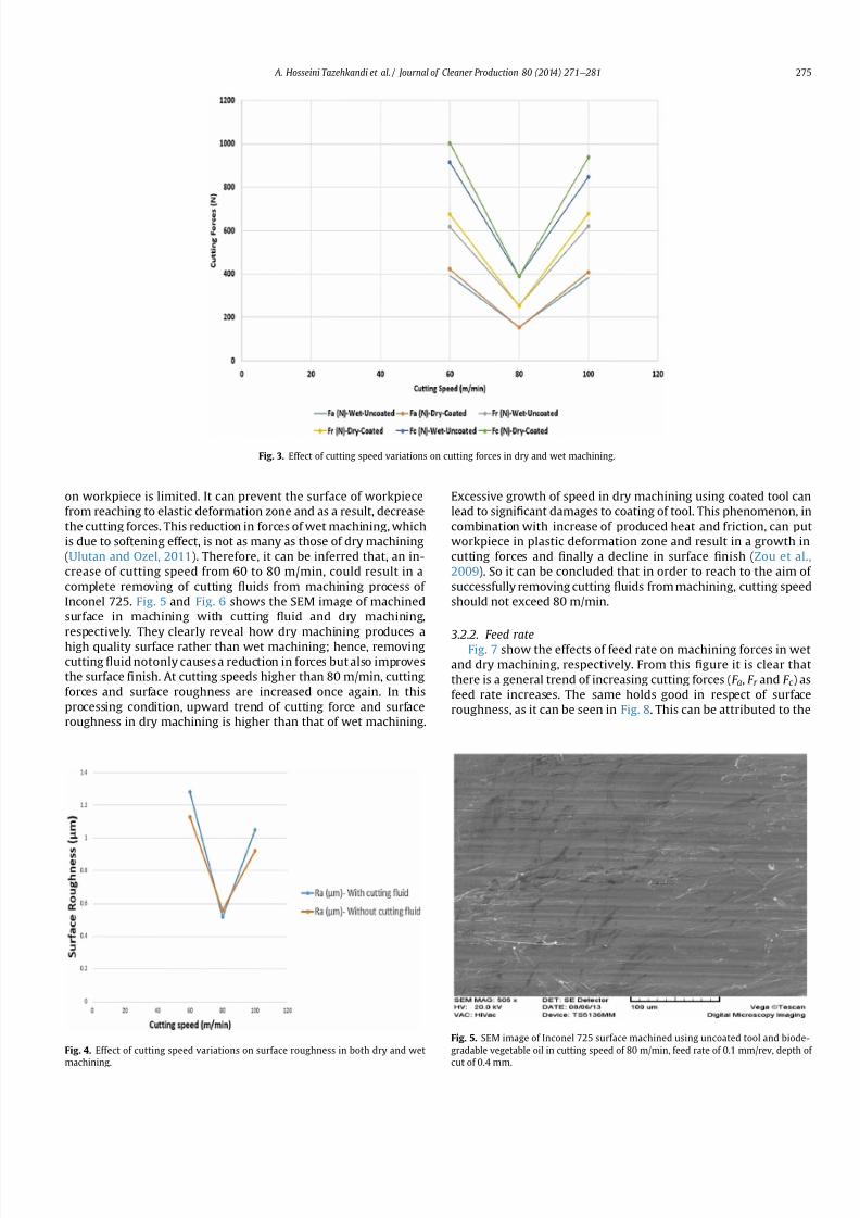
7212019 Journal of Cleaner ProductionExperimental Investigation On
httpslidepdfcomreaderfulljournal-of-cleaner-productionexperimental-investigation-on 511
7212019 Journal of Cleaner ProductionExperimental Investigation On
httpslidepdfcomreaderfulljournal-of-cleaner-productionexperimental-investigation-on 611
fact that an increase in feed rate results in formation of built e up e
edge by virtue of cold weld that take place between some pieces of
produced chips and cutting edge of tool Formation of built e up e
edge makes grooves on workpiece surface and this in turn not only
damages the surface of workpiece but also extremely increases the
cutting forces In dry machining with coated tool the coating of tool
can postpone formation of built e up e edge up to a point It can
abate the increasing trend of cutting forces and surface roughness
However in machining with uncoated tool high probability of
formation of built e up e edge induces higher cutting forces and
surface roughness (Settineri et al 2008) Considering the results
that are presented in Table 6 it can be observed that in machining
with cutting speed of 80 mmin even an increase in feed ratewould
result in lower values of cutting forces and surface roughness
compare with those achieved in wet machining Therefore at cut-ting speed of 80 mmin it is possible to remove the cutting 1047298uid
from turning process with any feed rate Fig 9 and Fig10 show SEMimages of workpiece surface in processing with cutting speed of
80 mmin feed rate of 02 mm and depth of cut of 04 mmrev in
wet and dry machining respectively By comparison with Fig 9
which is related to wet machining image of workpiece surface in
dry machining (Fig 10) has less grooves and hence has better
surface 1047297nish It is known that dry machining using excessive feed
rates causes signi1047297cant damages to coating of tool and on the other
hand since there is not any cutting 1047298uid in dry machining the
produced chips are willing to remain at surface of workpiece
Because of these two reasons built e up e edge was formed and
would be hardened during the turning process and therefore in-
duces deep grooves on workpiece surface with plastic deformations
on the edges of these grooves This can noticeably affect the me-
chanical properties of workpiece In some cases hardened built e
up e edge may break some parts of workpiece material and induces
various type of wear mechanisms so it is impossible to remove the
Fig 6 SEM image of Inconel 725 surface machined in dry condition using coated tool
in cutting speed of 80 mmin feed rate of 01 mmrev depth of cut of 04 mm
Fig 7 Effect of feed rate on cutting forces in dry and wet machining
Fig 8 Effect of feed rate on surface roughness in both dry and wet machining
A Hosseini Tazehkandi et al Journal of Cleaner Production 80 (2014) 271e 281276
7212019 Journal of Cleaner ProductionExperimental Investigation On
httpslidepdfcomreaderfulljournal-of-cleaner-productionexperimental-investigation-on 711
cutting1047298
uid On the other hand selecting very low levels of cuttingspeeds is not productive because of increase in special cutting en-
ergy consumption power of machine and machining time In other
words with the increase in consumption power of machine and
machining time the utilization of cutting 1047298uid and machining costs
considerably grow and tool and workpiece are exposed to higher
temperatures for a long period
Taking all above-mentioned discussion into consideration it can
be concluded that in selection of feed rate for purpose of removing
cutting 1047298uid it is very important to choose the appropriate ranges
of this parameter
323 Depth of cut
According to Fig 11 in both wet and dry machining an increase
in depth of cut results in increased cutting forces and Fig12 clearlyreveals that as cutting forces increase so does the surface rough-
ness of workpiece surface When the cutting speed of machining is
80 mmin increasing depth of cut induces higher material
removing rate Also tool coating plays an important role in
Fig 9 SEM image of workpiece surface in processing with cutting speed of 80 mmin
feed rate of02 mmand depthof cutof 04mmrevin wetmachiningwithuncoatedtool
Fig 10 SEM image of workpiece surface in processing with cutting speed of 80 mmin
feed rate of 02 mm and depth of cut of 04 mmrev in dry machining with coated tool
Fig 11 Effect of depth of cut variations on cutting forces in dry and wet machining
Fig 12 Effect of depth of cut variations on surface roughness in both dry and wet
machining
A Hosseini Tazehkandi et al Journal of Cleaner Production 80 (2014) 271e 281 277
7212019 Journal of Cleaner ProductionExperimental Investigation On
httpslidepdfcomreaderfulljournal-of-cleaner-productionexperimental-investigation-on 811
reducing friction between tool cutting edge and produced chips
which can retard the extreme growth of produced heat So higher
amount of depth of cut results in higher cutting forces However in
wet machining using uncoated tool as depth of cut increases
produced heat on surface of workpiece increases too It is known
that Inconel 725 has lower amount of heat transfer coef 1047297cient and
on the other hand cutting 1047298uid can only transfer a small part of
produced heat Therefore excessive heat on cutting surface in
combination with higher material removing rate would raise cut-
ting forces and deteriorate surface 1047297nish Finally increasing trend
of cutting forces in wet machining would be much more noticeable
than that of dry machining It can be concluded that in machining
with cutting speed of 80 mmin even in higher amount of depth of
cut it is possible to remove cutting 1047298uid from the process One
interesting point is that in dry machining with coated tool depth of
cut should not take values lower than radius of tool corner
(04 mm) otherwise cutting operation will be carried out through
tool corner instead of cutting edge In this condition ploughing
phenomenon can cause severe growth in cutting forces and dete-
rioration in surface 1047297nish (Ulutan and Ozel 2011) Fig 13 clearly
reveals how ploughing phenomenon can completely damage the
surface 1047297nish of workpiece
33 Analysis of variance (ANOVA)
The ANOVA method measures the effect of input variables on
response variables through the relationship between these three
sets of variables The purpose of ANOVA is to determine which
machining parameters highly affect the cutting forces and surface
roughness (Camposeco-Negrete 2013) The statistical signi1047297cance
of the 1047297tted quadratic models was evaluated by the P -values of the
ANOVA These values are given in Table 7 (for feed force-Dry)
Table 8 (for thrust force-Dry) Table 9 (for cutting force-Dry)
Table 10 (for surface roughness-Dry) Table 11 (for feed force-
Wet) Table 12 (for thrust force-Wet) Table 13 (for cutting force-
Wet) and Table 14 (for surface roughness-Wet) When P -valuesare less than 005 (or 95 con1047297dence) the obtained models are
considered to be statistically signi1047297cant It demonstrates that the
chosen parameters in model have signi1047297cant effect on the re-
sponses The F-value is an index used to check the adequacy of the
model (Bouacha et al 2010) In both dry and wet machining of
Inconel 725 cutting speed has remarkable effect on feed force andcutting force However cutting speed and cutting force are in order
of the most effective parameters on thrust force In the case of
Table 7
Analysis of variance for feed force (N) e in dry machining with coated tool
Term DOF Seq SS Adj SS Adj MS F P
Regression 9 149704 149704 166338 13652 0000
linear 3 131269 16313 54376 4463 0000
A 1 1682 16127 16127 13236 0000
B 1 6689 219 2187 180 0198
C 1 122897 17 168 014 0715
A2
1 16098 16481 4814 13527 0000B2 1 475 337 3371 277 0115
C2 1 736 821 8211 674 0019
AB 1 0 0 0 000 1000
AC 1 421 421 4213 346 0040
BC 1 705 705 7053 579 0028
Error 17 2071 2071 1218
Total 26 151775
R-Sq 9632
DOF frac14 Degree Of Freedom SS frac14 Sum of Squares MS or MSD frac14 Mean Square F frac14 F -
value P frac14 P -value
Dry frac14 dry machining with coated tool
Wet frac14 machining with cutting 1047298uid and uncoated tool
Table 8
Analysis of variance for thrust force (N) e in dry machining with coated tool
Term DOF Seq SS Adj SS Adj MS F P
Regression 9 344329 344329 382587 11974 0000
linear 3 281721 53015 176716 5531 0000
A 1 4232 51343 513427 16069 0000
B 1 28960 3780 37796 1183 0003
C 1 248529 1136 11362 356 0077
A2 1 47661 48797 487973 15273 0000
B2 1 4397 3628 36279 1135 0004
C2 1 1148 1471 14707 460 0047
AB 1 290 290 2901 091 0354AC 1 3391 3391 33909 1061 0005
BC 1 5720 5720 57203 1790 0001
Error 17 5432 5432 3195
Total 26 349760
R-Sq 9570
DOF frac14 Degree Of Freedom SS frac14 Sum of Squares MS or MSD frac14 Mean Square F frac14 F -
value P frac14 P -value
Dry frac14 dry machining with coated tool
Wet frac14 machining with cutting 1047298uid and uncoated tool
Table 9
Analysis of variance for cutting force (N) e in dry machining with coated tool
Term DOF Seq SS Adj SS Adj MS F P
Regression 9 63145 613145 68127 6600 0000
linear 3 436807 163532 54511 5281 0000
A 1 27691 161302 161302 1 5627 0 000
B 1 20469 68 68 007 0800
C 1 388647 321 321 031 0584
A2 1 167056 169420 57389 16413 0000
B2 1 329 127 127 012 0730
C2 1 4349 4563 4563 442 0051
AB 1 44 44 44 004 0839
AC 1 526 526 526 051 0485
BC 1 4033 4033 4033 391 0065
Error 17 17548 17548 1032
Total 26 630693
R-Sq 9352
DOF frac14 Degree Of Freedom SS frac14 Sum of Squares MS or MSD frac14 Mean Square F frac14 F -
value P frac14 P -value
Dry frac14 dry machining with coated tool
Wetfrac14
machining with cutting 1047298
uid and uncoated tool
Fig 13 SEM image surface of Inconel 725 in dry machining with cutting speed of
80 mmin feed rate of 02 mm and depth of cut of 01 mm for showing ploughing
phenomenon
A Hosseini Tazehkandi et al Journal of Cleaner Production 80 (2014) 271e 281278
7212019 Journal of Cleaner ProductionExperimental Investigation On
httpslidepdfcomreaderfulljournal-of-cleaner-productionexperimental-investigation-on 911
surface 1047297nish these parameters are cutting and feed force The
effectiveness of the models for feed force thrust force cutting force
and surface roughness can be further analyzed with help of the R-
Sq values A higher value of R-Sq is always desirable
34 Regression equations
The relationship between the factors and performance mea-surements were modeled by quartic regression Using these
equations it is possible to achieve the values of machining force
components and surface roughness in both wet and dry conditions
It should be noted that the amount of input parameters needs to be
within the selected ranges As it is presented in ANOVA
Tables 7e14 the parameters with P values less than 005 have less
impact on results of experiments However in order to achieve the
maximum precision and minimum possible error in regression
models 1 to 8 even effect of the less effective machining parame-
ters and counter-effect of them have been taken into account The
cutting parameters of cutting speed feed rate and depth of cut are
represented by symbols of A B and C respectively The obtained
regression equations were as follows
Thefeed force in drymachining model (F a)isgivenbelowinEq (1)
F afrac1410846219Athorn01A2thorn737C2
thorn07ACthorn3833BC (1)
The thrust force in dry machining model (F r ) is given by Eq (2)
F r frac14 2099 391A 3431B thorn 02A2thorn 98893B2
thorn 987C2
thorn 22ACthorn 10916BC (2)
The cutting force model in dry machining (F c ) is given by Eq (3)
Table 10
Analysisof Variance for Surface roughness(mm) ein dry machining withcoated tool
Term DOF Seq SS Adj SS Adj MS F P
Regression 9 119808 116808 0133120 27633 0000
linear 3 063877 057267 0190890 39625 0000
A 1 016056 049409 0494090 102564 0000
B 1 047694 003425 0034255 7111 0000
C 1 000128 000066 0000657 136 0259
A2
1 054101 053815 0538149 11171 0000B2 1 001251 001190 0011905 2471 0000
C2 1 000056 000057 0000566 118 0293
AB 1 000521 000521 0005208 1081 0004
AC 1 000002 000002 0000015 003 00861
BC 1 000001 000001 0000008 002 0897
Error 17 000819 000819 0000482
Total 26 120627
R-Sq 9832
DOF frac14 Degree Of Freedom SS frac14 Sum of Squares MS or MSD frac14 Mean Square F frac14 F -
value P frac14 P -value
Dry frac14 dry machining with coated tool
Wet frac14 machining with cutting 1047298uid and uncoated tool
Table 11
Analysis of variance for feed force (N) e in wet machining with uncoated tool
Term DOF Seq SS Adj SS Adj MS F P
Regression 9 138468 138468 15385 12069 0000
linear 3 134374 2302 7673 602 0005
A 1 1721 2163 2163 1697 0001
B 1 7240 248 2479 194 0181
C 1 125413 14 135 011 0749
A2 1 1719 1853 1853 787 0001
B2 1 520 377 377 296 0104
C2 1 687 772 772 606 0025
AB 1 0 0 03 000 0960
AC 1 447 447 4466 350 0079
BC 1 721 721 7207 565 0029
Error 17 2167 2167 1275
Total 26 140635
R-Sq 9573
DOF frac14 Degree Of Freedom SS frac14 Sum of Squares MS or MSD frac14 Mean Square F frac14 F -value P frac14 P -value
Dry frac14 dry machining with coated tool
Wet frac14 machining with cutting 1047298uid and uncoated tool
Table 12
Analysis of variance for thrust force (N) e in wet machining with uncoated tool
Term DOF Seq SS Adj SS Adj MS F P
Regression 9 308682 308682 34298 13107 0000
linear 3 290198 9127 30422 1163 0000
A 1 4418 5515 55152 2108 0000
B 1 31920 3758 37577 1436 0001
C 1 253860 1174 11738 449 0049
A2 1 3278 3608 36078 1379 0002
B2 1 4458 3677 36772 1405 0002
C2 1 1212 1539 15391 588 0027
AB 1 280 280 2803 107 0315
AC 1 3314 3314 33142 1267 0002
BC 1 5941 5941 59407 2270 0000
Error 17 4448 4448 2617
Total 26 313131
R-Sq 9598
DOF frac14 Degree Of Freedom SS frac14 Sum of Squares MS or MSD frac14 Mean Square F frac14 F -
value P frac14 P -value
Dry frac14 dry machining with coated tool
Wetfrac14
machining with cutting 1047298
uid and uncoated tool
Table 13
Analysis of variance for cutting force (N) e in wet machining with uncoated tool
Term DOF Seq SS Adj SS Adj MS F P
Regression 9 489771 489771 54419 5245 0000
linear 3 452132 30067 100223 966 0001
A 1 28691 29954 299538 2887 0000
B 1 23545 36 361 003 0854
C 1 400897 401 4007 039 0543
A2
1 27855 28876 289763 2793 0000B2 1 284 95 945 009 0766
C2 1 4817 5040 50402 486 0042
AB 1 48 4684 15612 005 0832
AC 1 529 48 480 051 0485
BC 1 4107 529 5285 396 0063
Error 17 17638 4107 41070
Total 26 507409 17638 10375
R-Sq 9173
DOF frac14 Degree Of Freedom SS frac14 Sum of Squares MS or MSD frac14 Mean Square F frac14 F -
value P frac14 P -value
Dry frac14 dry machining with coated tool
Wet frac14 machining with cutting 1047298uid and uncoated tool
Table 14
Analysis of variance for surface roughness (mm) e in wet machining with uncoated
tool
Term DOF Seq SS Adj SS Adj MS F P
Regression 9 0759871 0759871 0084430 17641 0000
linear 3 0605476 0185149 0061716 12895 0000
A 1 0131756 0126925 0126925 26521 0000
B 1 0473689 0040946 0040946 8555 0000
C 1 0000031 0000004 0000004 001 0930
A2 1 0131131 0130791 0130791 27328 0000
B2 1 0018641 0018406 0018406 3846 0000
C2 1 0000291 0000225 0000225 047 0502
AB 1 0003675 0003675 0003675 768 0013
AC 1 0000649 0000649 0000649 136 0260
BC 1 00000080 0000008 0000008 002 0897
Error 17 0008136 0008136 0000479
Total 26 0768007
R-Sq 9825
DOF frac14 Degree Of Freedom SS frac14 Sum of Squares MS or MSD frac14 Mean Square F frac14 F -
value P frac14 P -value
Dry frac14 dry machining with coated tool
Wetfrac14
machining with cutting 1047298
uid and uncoated tool
A Hosseini Tazehkandi et al Journal of Cleaner Production 80 (2014) 271e 281 279
7212019 Journal of Cleaner ProductionExperimental Investigation On
httpslidepdfcomreaderfulljournal-of-cleaner-productionexperimental-investigation-on 1011
F c frac14 32808 694Athorn 04A2thorn 1738C2 (3)
The surface roughness model in dry machining (Ra) is given by
Eq (4)
Ra frac14 47 01Athorn 103Bthorn 00007A2 179B2
002AB (4)
The feed force in wet machining model (F a) is given below in Eq
(5)
F a frac14 5349 81Athorn 004A2thorn 715C2
thorn 3875BC (5)
The thrust force in wet machining model (F r ) is given by Eq (6)
F r frac14 10508 128A 342B 195C thorn 006A2thorn 9956B2
thorn 101C2thorn 22ACthorn 11125BC (6)
The cutting force model in wet machining (F c ) is given byEq (7)
F c frac14 1699 30Athorn 02A2thorn 1826C2 (7)
The surface roughness model in wet machining (Ra) is given by
Eq (8)
Ra frac14 23 006Athorn 113Bthorn 00004A2 22B2 002AB (8)
35 Optimization of cutting conditions
It was assumed that the optimal manufacturing conditions for
turning of Inconel 725 without cutting 1047298uid are those with mini-
mum values of cutting forces (F a F r and F c ) and surface roughness
(Ra) during the turning process It is worth noting that although
main aim of this research is removing cutting 1047298uid from machining
process some operating condition make it mandatory to utilize
cutting 1047298uid So additional study has been presented to optimizing
consumption of cutting 1047298uid during wet machining of Inconel 725
The objective of optimizing the turning process of Inconel 725
with and without cutting 1047298uid is to achieve the minimum possiblelevel of machining force components and maximum level of surface
1047297nish Therefore the optimization has been carried out with taking
the attainment of minimum cutting feed and thrust forces and
maximum surface 1047297nish into account The experiments are also
conducted practically using the provided numbers for the param-
eters A (cutting speed) B (feed rate) and C (depth of cut) in both dry
and wet machining conditions by Minitab software in order to
demonstrate the differences between the values of predicted re-
sponses and the experimental values The results of RSM procedure
have been validated using the output of experiments and it was
con1047297rmed that value of error in RSM method in dry and wet con-
ditions is less than 5 percent Table 15 and Table 16 show the RSM
optimization results for cutting forces and surface roughness in dry
and wet machining
4 Conclusion
In this study effects of process parameters (which include
cutting speed feed rate and depth of cut) and tool coating on
machining forces and surface roughness were investigated in both
dry and wet machining of nickel-based superalloy Inconel 725 in
order to remove the cutting 1047298uid and meet environmental de-
mands Considering environmental problems Biodegradablevegetable oil was utilized as cutting 1047298uid in wet machining All
experiments were carried out in full factorial method and they
were analyzed using RSM and ANOVA methods Finally optimized
parameters were achieved for both dry and wet machining The
foremost conclusions which can be drawn are as follows
Removal of cutting 1047298uid in the above-mentioned conditions
result in reduced production costs and 1047298uid production ex-
penses This in turn reduces costs of removing it from the ma-
chine and the parts and eliminates destructive effect of these
1047298uids on the environment and human health
The role of tool coating in reduction of cutting forces and
improving surface 1047297nish is much more effective than using
cutting 1047298uid Since Inconel 725 is one of the dif 1047297cult-to-cut
materials excessive heat was produced during turning and
remained on workpiece surface due to low heat transfer ca-
pacity of cutting 1047298uid However coating of tool reduced friction
and as a result made it possible to remove the cutting 1047298uid
When Inconel 725 was machined with cutting speed of 80 m
min regardless of the values of feed rate and depth of cut it was
quite feasible to eliminated cutting 1047298uid from turning process
In order to reach to the aim of successfully removing cutting
1047298uids from wet and dry machining cutting speed should not
exceed 80 mmin because it induced higher cutting forces and
deteriorated surface 1047297nish
Excessive increase of cutting speed could damage tool coating
and make it practically impossible to remove cutting 1047298uid
There was a general trend of increasing cutting forces and sur-
face roughness as feed rate and depth of cut increase
References
Aouici H Yallese MA Chaoui K Mabrouki T Rigal J-F 2012 Analysis of sur-face roughness and cutting force components in hard turning with CBN toolprediction model and cutting conditions optimization Measurement 45344e353
Bouacha K Yallese MA Mabrouki T Rigal J-F 2010 Statistical analysis of sur-face roughness and cutting forces using response surface methodology in hardturning of AISI 52100 bearing steel with CBN tool Int J Refract Metals HardMater 28 349e361
Camposeco-Negrete C 2013 Optimization of cutting parameters for minimizingenergy consumption in turning of AISI 6061 T6 using Taguchi methodology andANOVA J Clean Prod 53 195e203
Davim JP 2013 Green Manufacturing Processes and Systems Springer London
UK
Table 15
The improved values for dry machining of Inconel 725
Cutting speed
(mmin)
Feed rate
(mmrev)
Depth of
cut (mm)
Feed force (N) Thrust force (N) Cutting force (N) Surface roughness
(mm)
Error
Predicted values 822 01 04 15834 25727 42801 0492 5
Experimental values 822 01 04 16413 26922 44179 051 e
Table 16
The improved values for wet machining of Inconel 725
Cutting speed
(mmin)
Feed rate
(mmrev)
Depth of
cut (mm)
Feed force (N) Thrust force (N) Cutting force (N) Surface roughness
(mm)
Error
Predicted values 896 01 04 1604 2567 43045 051 5
Experimental values 896 01 04 16729 2669 45240 054 e
A Hosseini Tazehkandi et al Journal of Cleaner Production 80 (2014) 271e 281280
7212019 Journal of Cleaner ProductionExperimental Investigation On
httpslidepdfcomreaderfulljournal-of-cleaner-productionexperimental-investigation-on 1111
Davoodi B Tazehkandi AH 2014 Experimental investigation and optimization of cutting parameters in dry and wet machining of aluminum alloy 5083 in orderto remove cutting 1047298uid J Clean Prod 68 234e242 httpdxdoiorg101016
jjclepro201312056Devillez A Le Coz G Dominiak S Dudzinski D 2011 Dry machining of Inconel
718 workpiece surface integrity J Mater Process Technol 211 1590e1598Ezilarasan C Velayudham A January 2013 An experimental analysis and
measurement of process performances in machining of nimonic C-263super alloy Measurement 46 (1) 185e199 httpdxdoiorg101016
jmeasurement201206006
Fratila D Caizar C 2011 Application of Taguchi method to selection of optimallubrication and cutting conditions in face milling of AlMg 3 J Clean Prod 19640e645
Groover MP 2007 Fundamentals of Modern Manufacturing Materials Processesand Systems Wiley com United States of America
Kuram E Ozcelik B Bayramoglu M Demirbas E Simsek BT 2012 Optimizationof cutting 1047298uids and cutting parameters during end milling by using D-optimaldesign of experiments J Clean Prod
Kuram E Ozcelik B Demirbas E 2013 Environmentally Friendly MachiningVegetable Based Cutting Fluids Green Manufacturing Processes and SystemsSpringer pp 23e47
Lalwani D Mehta N Jain P 2008 Experimental investigations of cutting pa-rameters in1047298uence on cutting forces and surface roughness in 1047297nish hardturning of MDN250 steel J Mater Process Technol 206 167e179
Lawal SA Choudhury IA Nukman Y 2013 A critical assessment of lubricationtechniques in machining processes a case for minimum quantity lubricationusing vegetable oil-based lubricant J Clean Prod 41 210e221
Mandal N Doloi B Mondal B Das R 2011 Optimization of 1047298ank wear usingZirconia Toughened Alumina (ZTA) cutting tool Taguchi method and Regres-sion analysis Measurement 44 2149e2155
Nalbant M Altın A Geurookkaya H 2007 The effect of cutting speed and cutting toolgeometry on machinability properties of nickel-base Inconel 718 super alloysMater Des 28 1334e1338
Sarıkaya M Guumllluuml A 2014 Taguchi design and response surface methodology
based analysis of machining parameters in CNC turning under MQL J CleanProd 65 604e616
Settineri L Faga MG Lerga B 2008 Properties and performances of innovativecoated tools for turning inconel Int J Mach Tools Manuf 48 815e823
Ulutan D Ozel T 2011 Machining induced surface integrity in titanium and nickelalloys a review Int J Mach Tools Manuf 51 250e280
Weinert K Inasaki I Sutherland J Wakabayashi T 2004 Dry machining andminimum quantity lubrication CIRP Ann Manuf Techn 53 511e537
Zhang S Li J Wang Y 2012 Tool life and cutting forces in end milling Inconel 718under dry and minimum quantity cooling lubrication cutting conditions
J Clean Prod 32 81e87ZouB ChenM Huang CAnQ 2009 Studyon surface damages causedby turning
NiCr20TiAl nickel-based alloy J Mater Process Technol 209 5802e5809
A Hosseini Tazehkandi et al Journal of Cleaner Production 80 (2014) 271e 281 281
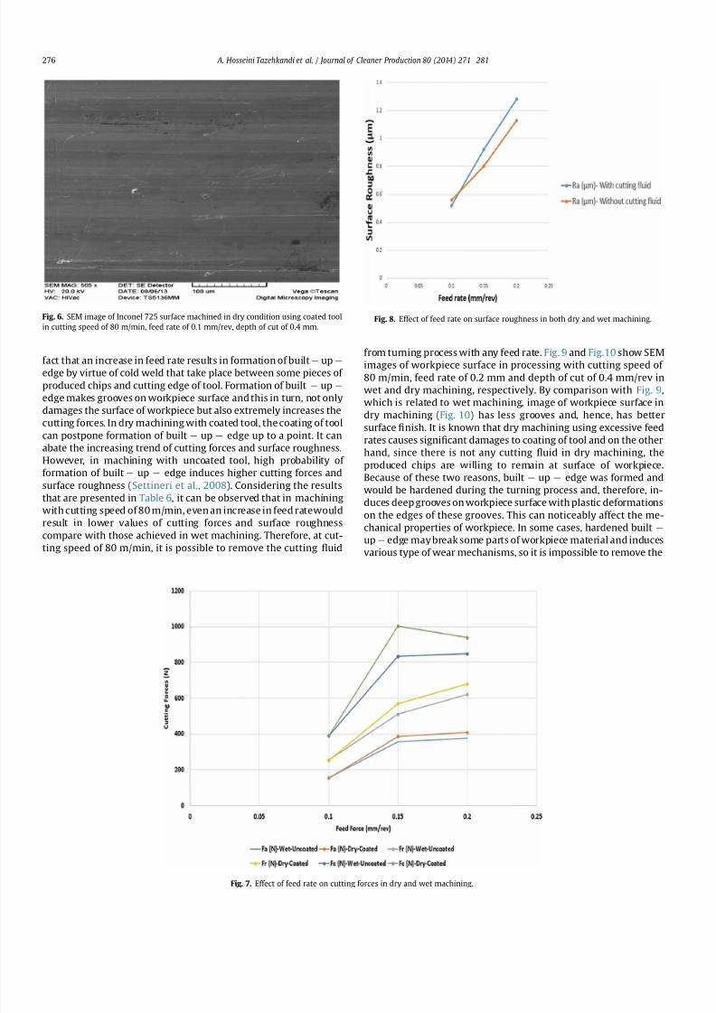
7212019 Journal of Cleaner ProductionExperimental Investigation On
httpslidepdfcomreaderfulljournal-of-cleaner-productionexperimental-investigation-on 611
fact that an increase in feed rate results in formation of built e up e
edge by virtue of cold weld that take place between some pieces of
produced chips and cutting edge of tool Formation of built e up e
edge makes grooves on workpiece surface and this in turn not only
damages the surface of workpiece but also extremely increases the
cutting forces In dry machining with coated tool the coating of tool
can postpone formation of built e up e edge up to a point It can
abate the increasing trend of cutting forces and surface roughness
However in machining with uncoated tool high probability of
formation of built e up e edge induces higher cutting forces and
surface roughness (Settineri et al 2008) Considering the results
that are presented in Table 6 it can be observed that in machining
with cutting speed of 80 mmin even an increase in feed ratewould
result in lower values of cutting forces and surface roughness
compare with those achieved in wet machining Therefore at cut-ting speed of 80 mmin it is possible to remove the cutting 1047298uid
from turning process with any feed rate Fig 9 and Fig10 show SEMimages of workpiece surface in processing with cutting speed of
80 mmin feed rate of 02 mm and depth of cut of 04 mmrev in
wet and dry machining respectively By comparison with Fig 9
which is related to wet machining image of workpiece surface in
dry machining (Fig 10) has less grooves and hence has better
surface 1047297nish It is known that dry machining using excessive feed
rates causes signi1047297cant damages to coating of tool and on the other
hand since there is not any cutting 1047298uid in dry machining the
produced chips are willing to remain at surface of workpiece
Because of these two reasons built e up e edge was formed and
would be hardened during the turning process and therefore in-
duces deep grooves on workpiece surface with plastic deformations
on the edges of these grooves This can noticeably affect the me-
chanical properties of workpiece In some cases hardened built e
up e edge may break some parts of workpiece material and induces
various type of wear mechanisms so it is impossible to remove the
Fig 6 SEM image of Inconel 725 surface machined in dry condition using coated tool
in cutting speed of 80 mmin feed rate of 01 mmrev depth of cut of 04 mm
Fig 7 Effect of feed rate on cutting forces in dry and wet machining
Fig 8 Effect of feed rate on surface roughness in both dry and wet machining
A Hosseini Tazehkandi et al Journal of Cleaner Production 80 (2014) 271e 281276
7212019 Journal of Cleaner ProductionExperimental Investigation On
httpslidepdfcomreaderfulljournal-of-cleaner-productionexperimental-investigation-on 711
cutting1047298
uid On the other hand selecting very low levels of cuttingspeeds is not productive because of increase in special cutting en-
ergy consumption power of machine and machining time In other
words with the increase in consumption power of machine and
machining time the utilization of cutting 1047298uid and machining costs
considerably grow and tool and workpiece are exposed to higher
temperatures for a long period
Taking all above-mentioned discussion into consideration it can
be concluded that in selection of feed rate for purpose of removing
cutting 1047298uid it is very important to choose the appropriate ranges
of this parameter
323 Depth of cut
According to Fig 11 in both wet and dry machining an increase
in depth of cut results in increased cutting forces and Fig12 clearlyreveals that as cutting forces increase so does the surface rough-
ness of workpiece surface When the cutting speed of machining is
80 mmin increasing depth of cut induces higher material
removing rate Also tool coating plays an important role in
Fig 9 SEM image of workpiece surface in processing with cutting speed of 80 mmin
feed rate of02 mmand depthof cutof 04mmrevin wetmachiningwithuncoatedtool
Fig 10 SEM image of workpiece surface in processing with cutting speed of 80 mmin
feed rate of 02 mm and depth of cut of 04 mmrev in dry machining with coated tool
Fig 11 Effect of depth of cut variations on cutting forces in dry and wet machining
Fig 12 Effect of depth of cut variations on surface roughness in both dry and wet
machining
A Hosseini Tazehkandi et al Journal of Cleaner Production 80 (2014) 271e 281 277
7212019 Journal of Cleaner ProductionExperimental Investigation On
httpslidepdfcomreaderfulljournal-of-cleaner-productionexperimental-investigation-on 811
reducing friction between tool cutting edge and produced chips
which can retard the extreme growth of produced heat So higher
amount of depth of cut results in higher cutting forces However in
wet machining using uncoated tool as depth of cut increases
produced heat on surface of workpiece increases too It is known
that Inconel 725 has lower amount of heat transfer coef 1047297cient and
on the other hand cutting 1047298uid can only transfer a small part of
produced heat Therefore excessive heat on cutting surface in
combination with higher material removing rate would raise cut-
ting forces and deteriorate surface 1047297nish Finally increasing trend
of cutting forces in wet machining would be much more noticeable
than that of dry machining It can be concluded that in machining
with cutting speed of 80 mmin even in higher amount of depth of
cut it is possible to remove cutting 1047298uid from the process One
interesting point is that in dry machining with coated tool depth of
cut should not take values lower than radius of tool corner
(04 mm) otherwise cutting operation will be carried out through
tool corner instead of cutting edge In this condition ploughing
phenomenon can cause severe growth in cutting forces and dete-
rioration in surface 1047297nish (Ulutan and Ozel 2011) Fig 13 clearly
reveals how ploughing phenomenon can completely damage the
surface 1047297nish of workpiece
33 Analysis of variance (ANOVA)
The ANOVA method measures the effect of input variables on
response variables through the relationship between these three
sets of variables The purpose of ANOVA is to determine which
machining parameters highly affect the cutting forces and surface
roughness (Camposeco-Negrete 2013) The statistical signi1047297cance
of the 1047297tted quadratic models was evaluated by the P -values of the
ANOVA These values are given in Table 7 (for feed force-Dry)
Table 8 (for thrust force-Dry) Table 9 (for cutting force-Dry)
Table 10 (for surface roughness-Dry) Table 11 (for feed force-
Wet) Table 12 (for thrust force-Wet) Table 13 (for cutting force-
Wet) and Table 14 (for surface roughness-Wet) When P -valuesare less than 005 (or 95 con1047297dence) the obtained models are
considered to be statistically signi1047297cant It demonstrates that the
chosen parameters in model have signi1047297cant effect on the re-
sponses The F-value is an index used to check the adequacy of the
model (Bouacha et al 2010) In both dry and wet machining of
Inconel 725 cutting speed has remarkable effect on feed force andcutting force However cutting speed and cutting force are in order
of the most effective parameters on thrust force In the case of
Table 7
Analysis of variance for feed force (N) e in dry machining with coated tool
Term DOF Seq SS Adj SS Adj MS F P
Regression 9 149704 149704 166338 13652 0000
linear 3 131269 16313 54376 4463 0000
A 1 1682 16127 16127 13236 0000
B 1 6689 219 2187 180 0198
C 1 122897 17 168 014 0715
A2
1 16098 16481 4814 13527 0000B2 1 475 337 3371 277 0115
C2 1 736 821 8211 674 0019
AB 1 0 0 0 000 1000
AC 1 421 421 4213 346 0040
BC 1 705 705 7053 579 0028
Error 17 2071 2071 1218
Total 26 151775
R-Sq 9632
DOF frac14 Degree Of Freedom SS frac14 Sum of Squares MS or MSD frac14 Mean Square F frac14 F -
value P frac14 P -value
Dry frac14 dry machining with coated tool
Wet frac14 machining with cutting 1047298uid and uncoated tool
Table 8
Analysis of variance for thrust force (N) e in dry machining with coated tool
Term DOF Seq SS Adj SS Adj MS F P
Regression 9 344329 344329 382587 11974 0000
linear 3 281721 53015 176716 5531 0000
A 1 4232 51343 513427 16069 0000
B 1 28960 3780 37796 1183 0003
C 1 248529 1136 11362 356 0077
A2 1 47661 48797 487973 15273 0000
B2 1 4397 3628 36279 1135 0004
C2 1 1148 1471 14707 460 0047
AB 1 290 290 2901 091 0354AC 1 3391 3391 33909 1061 0005
BC 1 5720 5720 57203 1790 0001
Error 17 5432 5432 3195
Total 26 349760
R-Sq 9570
DOF frac14 Degree Of Freedom SS frac14 Sum of Squares MS or MSD frac14 Mean Square F frac14 F -
value P frac14 P -value
Dry frac14 dry machining with coated tool
Wet frac14 machining with cutting 1047298uid and uncoated tool
Table 9
Analysis of variance for cutting force (N) e in dry machining with coated tool
Term DOF Seq SS Adj SS Adj MS F P
Regression 9 63145 613145 68127 6600 0000
linear 3 436807 163532 54511 5281 0000
A 1 27691 161302 161302 1 5627 0 000
B 1 20469 68 68 007 0800
C 1 388647 321 321 031 0584
A2 1 167056 169420 57389 16413 0000
B2 1 329 127 127 012 0730
C2 1 4349 4563 4563 442 0051
AB 1 44 44 44 004 0839
AC 1 526 526 526 051 0485
BC 1 4033 4033 4033 391 0065
Error 17 17548 17548 1032
Total 26 630693
R-Sq 9352
DOF frac14 Degree Of Freedom SS frac14 Sum of Squares MS or MSD frac14 Mean Square F frac14 F -
value P frac14 P -value
Dry frac14 dry machining with coated tool
Wetfrac14
machining with cutting 1047298
uid and uncoated tool
Fig 13 SEM image surface of Inconel 725 in dry machining with cutting speed of
80 mmin feed rate of 02 mm and depth of cut of 01 mm for showing ploughing
phenomenon
A Hosseini Tazehkandi et al Journal of Cleaner Production 80 (2014) 271e 281278
7212019 Journal of Cleaner ProductionExperimental Investigation On
httpslidepdfcomreaderfulljournal-of-cleaner-productionexperimental-investigation-on 911
surface 1047297nish these parameters are cutting and feed force The
effectiveness of the models for feed force thrust force cutting force
and surface roughness can be further analyzed with help of the R-
Sq values A higher value of R-Sq is always desirable
34 Regression equations
The relationship between the factors and performance mea-surements were modeled by quartic regression Using these
equations it is possible to achieve the values of machining force
components and surface roughness in both wet and dry conditions
It should be noted that the amount of input parameters needs to be
within the selected ranges As it is presented in ANOVA
Tables 7e14 the parameters with P values less than 005 have less
impact on results of experiments However in order to achieve the
maximum precision and minimum possible error in regression
models 1 to 8 even effect of the less effective machining parame-
ters and counter-effect of them have been taken into account The
cutting parameters of cutting speed feed rate and depth of cut are
represented by symbols of A B and C respectively The obtained
regression equations were as follows
Thefeed force in drymachining model (F a)isgivenbelowinEq (1)
F afrac1410846219Athorn01A2thorn737C2
thorn07ACthorn3833BC (1)
The thrust force in dry machining model (F r ) is given by Eq (2)
F r frac14 2099 391A 3431B thorn 02A2thorn 98893B2
thorn 987C2
thorn 22ACthorn 10916BC (2)
The cutting force model in dry machining (F c ) is given by Eq (3)
Table 10
Analysisof Variance for Surface roughness(mm) ein dry machining withcoated tool
Term DOF Seq SS Adj SS Adj MS F P
Regression 9 119808 116808 0133120 27633 0000
linear 3 063877 057267 0190890 39625 0000
A 1 016056 049409 0494090 102564 0000
B 1 047694 003425 0034255 7111 0000
C 1 000128 000066 0000657 136 0259
A2
1 054101 053815 0538149 11171 0000B2 1 001251 001190 0011905 2471 0000
C2 1 000056 000057 0000566 118 0293
AB 1 000521 000521 0005208 1081 0004
AC 1 000002 000002 0000015 003 00861
BC 1 000001 000001 0000008 002 0897
Error 17 000819 000819 0000482
Total 26 120627
R-Sq 9832
DOF frac14 Degree Of Freedom SS frac14 Sum of Squares MS or MSD frac14 Mean Square F frac14 F -
value P frac14 P -value
Dry frac14 dry machining with coated tool
Wet frac14 machining with cutting 1047298uid and uncoated tool
Table 11
Analysis of variance for feed force (N) e in wet machining with uncoated tool
Term DOF Seq SS Adj SS Adj MS F P
Regression 9 138468 138468 15385 12069 0000
linear 3 134374 2302 7673 602 0005
A 1 1721 2163 2163 1697 0001
B 1 7240 248 2479 194 0181
C 1 125413 14 135 011 0749
A2 1 1719 1853 1853 787 0001
B2 1 520 377 377 296 0104
C2 1 687 772 772 606 0025
AB 1 0 0 03 000 0960
AC 1 447 447 4466 350 0079
BC 1 721 721 7207 565 0029
Error 17 2167 2167 1275
Total 26 140635
R-Sq 9573
DOF frac14 Degree Of Freedom SS frac14 Sum of Squares MS or MSD frac14 Mean Square F frac14 F -value P frac14 P -value
Dry frac14 dry machining with coated tool
Wet frac14 machining with cutting 1047298uid and uncoated tool
Table 12
Analysis of variance for thrust force (N) e in wet machining with uncoated tool
Term DOF Seq SS Adj SS Adj MS F P
Regression 9 308682 308682 34298 13107 0000
linear 3 290198 9127 30422 1163 0000
A 1 4418 5515 55152 2108 0000
B 1 31920 3758 37577 1436 0001
C 1 253860 1174 11738 449 0049
A2 1 3278 3608 36078 1379 0002
B2 1 4458 3677 36772 1405 0002
C2 1 1212 1539 15391 588 0027
AB 1 280 280 2803 107 0315
AC 1 3314 3314 33142 1267 0002
BC 1 5941 5941 59407 2270 0000
Error 17 4448 4448 2617
Total 26 313131
R-Sq 9598
DOF frac14 Degree Of Freedom SS frac14 Sum of Squares MS or MSD frac14 Mean Square F frac14 F -
value P frac14 P -value
Dry frac14 dry machining with coated tool
Wetfrac14
machining with cutting 1047298
uid and uncoated tool
Table 13
Analysis of variance for cutting force (N) e in wet machining with uncoated tool
Term DOF Seq SS Adj SS Adj MS F P
Regression 9 489771 489771 54419 5245 0000
linear 3 452132 30067 100223 966 0001
A 1 28691 29954 299538 2887 0000
B 1 23545 36 361 003 0854
C 1 400897 401 4007 039 0543
A2
1 27855 28876 289763 2793 0000B2 1 284 95 945 009 0766
C2 1 4817 5040 50402 486 0042
AB 1 48 4684 15612 005 0832
AC 1 529 48 480 051 0485
BC 1 4107 529 5285 396 0063
Error 17 17638 4107 41070
Total 26 507409 17638 10375
R-Sq 9173
DOF frac14 Degree Of Freedom SS frac14 Sum of Squares MS or MSD frac14 Mean Square F frac14 F -
value P frac14 P -value
Dry frac14 dry machining with coated tool
Wet frac14 machining with cutting 1047298uid and uncoated tool
Table 14
Analysis of variance for surface roughness (mm) e in wet machining with uncoated
tool
Term DOF Seq SS Adj SS Adj MS F P
Regression 9 0759871 0759871 0084430 17641 0000
linear 3 0605476 0185149 0061716 12895 0000
A 1 0131756 0126925 0126925 26521 0000
B 1 0473689 0040946 0040946 8555 0000
C 1 0000031 0000004 0000004 001 0930
A2 1 0131131 0130791 0130791 27328 0000
B2 1 0018641 0018406 0018406 3846 0000
C2 1 0000291 0000225 0000225 047 0502
AB 1 0003675 0003675 0003675 768 0013
AC 1 0000649 0000649 0000649 136 0260
BC 1 00000080 0000008 0000008 002 0897
Error 17 0008136 0008136 0000479
Total 26 0768007
R-Sq 9825
DOF frac14 Degree Of Freedom SS frac14 Sum of Squares MS or MSD frac14 Mean Square F frac14 F -
value P frac14 P -value
Dry frac14 dry machining with coated tool
Wetfrac14
machining with cutting 1047298
uid and uncoated tool
A Hosseini Tazehkandi et al Journal of Cleaner Production 80 (2014) 271e 281 279
7212019 Journal of Cleaner ProductionExperimental Investigation On
httpslidepdfcomreaderfulljournal-of-cleaner-productionexperimental-investigation-on 1011
F c frac14 32808 694Athorn 04A2thorn 1738C2 (3)
The surface roughness model in dry machining (Ra) is given by
Eq (4)
Ra frac14 47 01Athorn 103Bthorn 00007A2 179B2
002AB (4)
The feed force in wet machining model (F a) is given below in Eq
(5)
F a frac14 5349 81Athorn 004A2thorn 715C2
thorn 3875BC (5)
The thrust force in wet machining model (F r ) is given by Eq (6)
F r frac14 10508 128A 342B 195C thorn 006A2thorn 9956B2
thorn 101C2thorn 22ACthorn 11125BC (6)
The cutting force model in wet machining (F c ) is given byEq (7)
F c frac14 1699 30Athorn 02A2thorn 1826C2 (7)
The surface roughness model in wet machining (Ra) is given by
Eq (8)
Ra frac14 23 006Athorn 113Bthorn 00004A2 22B2 002AB (8)
35 Optimization of cutting conditions
It was assumed that the optimal manufacturing conditions for
turning of Inconel 725 without cutting 1047298uid are those with mini-
mum values of cutting forces (F a F r and F c ) and surface roughness
(Ra) during the turning process It is worth noting that although
main aim of this research is removing cutting 1047298uid from machining
process some operating condition make it mandatory to utilize
cutting 1047298uid So additional study has been presented to optimizing
consumption of cutting 1047298uid during wet machining of Inconel 725
The objective of optimizing the turning process of Inconel 725
with and without cutting 1047298uid is to achieve the minimum possiblelevel of machining force components and maximum level of surface
1047297nish Therefore the optimization has been carried out with taking
the attainment of minimum cutting feed and thrust forces and
maximum surface 1047297nish into account The experiments are also
conducted practically using the provided numbers for the param-
eters A (cutting speed) B (feed rate) and C (depth of cut) in both dry
and wet machining conditions by Minitab software in order to
demonstrate the differences between the values of predicted re-
sponses and the experimental values The results of RSM procedure
have been validated using the output of experiments and it was
con1047297rmed that value of error in RSM method in dry and wet con-
ditions is less than 5 percent Table 15 and Table 16 show the RSM
optimization results for cutting forces and surface roughness in dry
and wet machining
4 Conclusion
In this study effects of process parameters (which include
cutting speed feed rate and depth of cut) and tool coating on
machining forces and surface roughness were investigated in both
dry and wet machining of nickel-based superalloy Inconel 725 in
order to remove the cutting 1047298uid and meet environmental de-
mands Considering environmental problems Biodegradablevegetable oil was utilized as cutting 1047298uid in wet machining All
experiments were carried out in full factorial method and they
were analyzed using RSM and ANOVA methods Finally optimized
parameters were achieved for both dry and wet machining The
foremost conclusions which can be drawn are as follows
Removal of cutting 1047298uid in the above-mentioned conditions
result in reduced production costs and 1047298uid production ex-
penses This in turn reduces costs of removing it from the ma-
chine and the parts and eliminates destructive effect of these
1047298uids on the environment and human health
The role of tool coating in reduction of cutting forces and
improving surface 1047297nish is much more effective than using
cutting 1047298uid Since Inconel 725 is one of the dif 1047297cult-to-cut
materials excessive heat was produced during turning and
remained on workpiece surface due to low heat transfer ca-
pacity of cutting 1047298uid However coating of tool reduced friction
and as a result made it possible to remove the cutting 1047298uid
When Inconel 725 was machined with cutting speed of 80 m
min regardless of the values of feed rate and depth of cut it was
quite feasible to eliminated cutting 1047298uid from turning process
In order to reach to the aim of successfully removing cutting
1047298uids from wet and dry machining cutting speed should not
exceed 80 mmin because it induced higher cutting forces and
deteriorated surface 1047297nish
Excessive increase of cutting speed could damage tool coating
and make it practically impossible to remove cutting 1047298uid
There was a general trend of increasing cutting forces and sur-
face roughness as feed rate and depth of cut increase
References
Aouici H Yallese MA Chaoui K Mabrouki T Rigal J-F 2012 Analysis of sur-face roughness and cutting force components in hard turning with CBN toolprediction model and cutting conditions optimization Measurement 45344e353
Bouacha K Yallese MA Mabrouki T Rigal J-F 2010 Statistical analysis of sur-face roughness and cutting forces using response surface methodology in hardturning of AISI 52100 bearing steel with CBN tool Int J Refract Metals HardMater 28 349e361
Camposeco-Negrete C 2013 Optimization of cutting parameters for minimizingenergy consumption in turning of AISI 6061 T6 using Taguchi methodology andANOVA J Clean Prod 53 195e203
Davim JP 2013 Green Manufacturing Processes and Systems Springer London
UK
Table 15
The improved values for dry machining of Inconel 725
Cutting speed
(mmin)
Feed rate
(mmrev)
Depth of
cut (mm)
Feed force (N) Thrust force (N) Cutting force (N) Surface roughness
(mm)
Error
Predicted values 822 01 04 15834 25727 42801 0492 5
Experimental values 822 01 04 16413 26922 44179 051 e
Table 16
The improved values for wet machining of Inconel 725
Cutting speed
(mmin)
Feed rate
(mmrev)
Depth of
cut (mm)
Feed force (N) Thrust force (N) Cutting force (N) Surface roughness
(mm)
Error
Predicted values 896 01 04 1604 2567 43045 051 5
Experimental values 896 01 04 16729 2669 45240 054 e
A Hosseini Tazehkandi et al Journal of Cleaner Production 80 (2014) 271e 281280
7212019 Journal of Cleaner ProductionExperimental Investigation On
httpslidepdfcomreaderfulljournal-of-cleaner-productionexperimental-investigation-on 1111
Davoodi B Tazehkandi AH 2014 Experimental investigation and optimization of cutting parameters in dry and wet machining of aluminum alloy 5083 in orderto remove cutting 1047298uid J Clean Prod 68 234e242 httpdxdoiorg101016
jjclepro201312056Devillez A Le Coz G Dominiak S Dudzinski D 2011 Dry machining of Inconel
718 workpiece surface integrity J Mater Process Technol 211 1590e1598Ezilarasan C Velayudham A January 2013 An experimental analysis and
measurement of process performances in machining of nimonic C-263super alloy Measurement 46 (1) 185e199 httpdxdoiorg101016
jmeasurement201206006
Fratila D Caizar C 2011 Application of Taguchi method to selection of optimallubrication and cutting conditions in face milling of AlMg 3 J Clean Prod 19640e645
Groover MP 2007 Fundamentals of Modern Manufacturing Materials Processesand Systems Wiley com United States of America
Kuram E Ozcelik B Bayramoglu M Demirbas E Simsek BT 2012 Optimizationof cutting 1047298uids and cutting parameters during end milling by using D-optimaldesign of experiments J Clean Prod
Kuram E Ozcelik B Demirbas E 2013 Environmentally Friendly MachiningVegetable Based Cutting Fluids Green Manufacturing Processes and SystemsSpringer pp 23e47
Lalwani D Mehta N Jain P 2008 Experimental investigations of cutting pa-rameters in1047298uence on cutting forces and surface roughness in 1047297nish hardturning of MDN250 steel J Mater Process Technol 206 167e179
Lawal SA Choudhury IA Nukman Y 2013 A critical assessment of lubricationtechniques in machining processes a case for minimum quantity lubricationusing vegetable oil-based lubricant J Clean Prod 41 210e221
Mandal N Doloi B Mondal B Das R 2011 Optimization of 1047298ank wear usingZirconia Toughened Alumina (ZTA) cutting tool Taguchi method and Regres-sion analysis Measurement 44 2149e2155
Nalbant M Altın A Geurookkaya H 2007 The effect of cutting speed and cutting toolgeometry on machinability properties of nickel-base Inconel 718 super alloysMater Des 28 1334e1338
Sarıkaya M Guumllluuml A 2014 Taguchi design and response surface methodology
based analysis of machining parameters in CNC turning under MQL J CleanProd 65 604e616
Settineri L Faga MG Lerga B 2008 Properties and performances of innovativecoated tools for turning inconel Int J Mach Tools Manuf 48 815e823
Ulutan D Ozel T 2011 Machining induced surface integrity in titanium and nickelalloys a review Int J Mach Tools Manuf 51 250e280
Weinert K Inasaki I Sutherland J Wakabayashi T 2004 Dry machining andminimum quantity lubrication CIRP Ann Manuf Techn 53 511e537
Zhang S Li J Wang Y 2012 Tool life and cutting forces in end milling Inconel 718under dry and minimum quantity cooling lubrication cutting conditions
J Clean Prod 32 81e87ZouB ChenM Huang CAnQ 2009 Studyon surface damages causedby turning
NiCr20TiAl nickel-based alloy J Mater Process Technol 209 5802e5809
A Hosseini Tazehkandi et al Journal of Cleaner Production 80 (2014) 271e 281 281
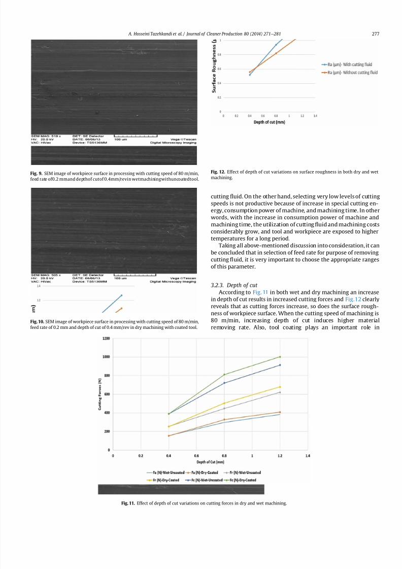
7212019 Journal of Cleaner ProductionExperimental Investigation On
httpslidepdfcomreaderfulljournal-of-cleaner-productionexperimental-investigation-on 711
cutting1047298
uid On the other hand selecting very low levels of cuttingspeeds is not productive because of increase in special cutting en-
ergy consumption power of machine and machining time In other
words with the increase in consumption power of machine and
machining time the utilization of cutting 1047298uid and machining costs
considerably grow and tool and workpiece are exposed to higher
temperatures for a long period
Taking all above-mentioned discussion into consideration it can
be concluded that in selection of feed rate for purpose of removing
cutting 1047298uid it is very important to choose the appropriate ranges
of this parameter
323 Depth of cut
According to Fig 11 in both wet and dry machining an increase
in depth of cut results in increased cutting forces and Fig12 clearlyreveals that as cutting forces increase so does the surface rough-
ness of workpiece surface When the cutting speed of machining is
80 mmin increasing depth of cut induces higher material
removing rate Also tool coating plays an important role in
Fig 9 SEM image of workpiece surface in processing with cutting speed of 80 mmin
feed rate of02 mmand depthof cutof 04mmrevin wetmachiningwithuncoatedtool
Fig 10 SEM image of workpiece surface in processing with cutting speed of 80 mmin
feed rate of 02 mm and depth of cut of 04 mmrev in dry machining with coated tool
Fig 11 Effect of depth of cut variations on cutting forces in dry and wet machining
Fig 12 Effect of depth of cut variations on surface roughness in both dry and wet
machining
A Hosseini Tazehkandi et al Journal of Cleaner Production 80 (2014) 271e 281 277
7212019 Journal of Cleaner ProductionExperimental Investigation On
httpslidepdfcomreaderfulljournal-of-cleaner-productionexperimental-investigation-on 811
reducing friction between tool cutting edge and produced chips
which can retard the extreme growth of produced heat So higher
amount of depth of cut results in higher cutting forces However in
wet machining using uncoated tool as depth of cut increases
produced heat on surface of workpiece increases too It is known
that Inconel 725 has lower amount of heat transfer coef 1047297cient and
on the other hand cutting 1047298uid can only transfer a small part of
produced heat Therefore excessive heat on cutting surface in
combination with higher material removing rate would raise cut-
ting forces and deteriorate surface 1047297nish Finally increasing trend
of cutting forces in wet machining would be much more noticeable
than that of dry machining It can be concluded that in machining
with cutting speed of 80 mmin even in higher amount of depth of
cut it is possible to remove cutting 1047298uid from the process One
interesting point is that in dry machining with coated tool depth of
cut should not take values lower than radius of tool corner
(04 mm) otherwise cutting operation will be carried out through
tool corner instead of cutting edge In this condition ploughing
phenomenon can cause severe growth in cutting forces and dete-
rioration in surface 1047297nish (Ulutan and Ozel 2011) Fig 13 clearly
reveals how ploughing phenomenon can completely damage the
surface 1047297nish of workpiece
33 Analysis of variance (ANOVA)
The ANOVA method measures the effect of input variables on
response variables through the relationship between these three
sets of variables The purpose of ANOVA is to determine which
machining parameters highly affect the cutting forces and surface
roughness (Camposeco-Negrete 2013) The statistical signi1047297cance
of the 1047297tted quadratic models was evaluated by the P -values of the
ANOVA These values are given in Table 7 (for feed force-Dry)
Table 8 (for thrust force-Dry) Table 9 (for cutting force-Dry)
Table 10 (for surface roughness-Dry) Table 11 (for feed force-
Wet) Table 12 (for thrust force-Wet) Table 13 (for cutting force-
Wet) and Table 14 (for surface roughness-Wet) When P -valuesare less than 005 (or 95 con1047297dence) the obtained models are
considered to be statistically signi1047297cant It demonstrates that the
chosen parameters in model have signi1047297cant effect on the re-
sponses The F-value is an index used to check the adequacy of the
model (Bouacha et al 2010) In both dry and wet machining of
Inconel 725 cutting speed has remarkable effect on feed force andcutting force However cutting speed and cutting force are in order
of the most effective parameters on thrust force In the case of
Table 7
Analysis of variance for feed force (N) e in dry machining with coated tool
Term DOF Seq SS Adj SS Adj MS F P
Regression 9 149704 149704 166338 13652 0000
linear 3 131269 16313 54376 4463 0000
A 1 1682 16127 16127 13236 0000
B 1 6689 219 2187 180 0198
C 1 122897 17 168 014 0715
A2
1 16098 16481 4814 13527 0000B2 1 475 337 3371 277 0115
C2 1 736 821 8211 674 0019
AB 1 0 0 0 000 1000
AC 1 421 421 4213 346 0040
BC 1 705 705 7053 579 0028
Error 17 2071 2071 1218
Total 26 151775
R-Sq 9632
DOF frac14 Degree Of Freedom SS frac14 Sum of Squares MS or MSD frac14 Mean Square F frac14 F -
value P frac14 P -value
Dry frac14 dry machining with coated tool
Wet frac14 machining with cutting 1047298uid and uncoated tool
Table 8
Analysis of variance for thrust force (N) e in dry machining with coated tool
Term DOF Seq SS Adj SS Adj MS F P
Regression 9 344329 344329 382587 11974 0000
linear 3 281721 53015 176716 5531 0000
A 1 4232 51343 513427 16069 0000
B 1 28960 3780 37796 1183 0003
C 1 248529 1136 11362 356 0077
A2 1 47661 48797 487973 15273 0000
B2 1 4397 3628 36279 1135 0004
C2 1 1148 1471 14707 460 0047
AB 1 290 290 2901 091 0354AC 1 3391 3391 33909 1061 0005
BC 1 5720 5720 57203 1790 0001
Error 17 5432 5432 3195
Total 26 349760
R-Sq 9570
DOF frac14 Degree Of Freedom SS frac14 Sum of Squares MS or MSD frac14 Mean Square F frac14 F -
value P frac14 P -value
Dry frac14 dry machining with coated tool
Wet frac14 machining with cutting 1047298uid and uncoated tool
Table 9
Analysis of variance for cutting force (N) e in dry machining with coated tool
Term DOF Seq SS Adj SS Adj MS F P
Regression 9 63145 613145 68127 6600 0000
linear 3 436807 163532 54511 5281 0000
A 1 27691 161302 161302 1 5627 0 000
B 1 20469 68 68 007 0800
C 1 388647 321 321 031 0584
A2 1 167056 169420 57389 16413 0000
B2 1 329 127 127 012 0730
C2 1 4349 4563 4563 442 0051
AB 1 44 44 44 004 0839
AC 1 526 526 526 051 0485
BC 1 4033 4033 4033 391 0065
Error 17 17548 17548 1032
Total 26 630693
R-Sq 9352
DOF frac14 Degree Of Freedom SS frac14 Sum of Squares MS or MSD frac14 Mean Square F frac14 F -
value P frac14 P -value
Dry frac14 dry machining with coated tool
Wetfrac14
machining with cutting 1047298
uid and uncoated tool
Fig 13 SEM image surface of Inconel 725 in dry machining with cutting speed of
80 mmin feed rate of 02 mm and depth of cut of 01 mm for showing ploughing
phenomenon
A Hosseini Tazehkandi et al Journal of Cleaner Production 80 (2014) 271e 281278
7212019 Journal of Cleaner ProductionExperimental Investigation On
httpslidepdfcomreaderfulljournal-of-cleaner-productionexperimental-investigation-on 911
surface 1047297nish these parameters are cutting and feed force The
effectiveness of the models for feed force thrust force cutting force
and surface roughness can be further analyzed with help of the R-
Sq values A higher value of R-Sq is always desirable
34 Regression equations
The relationship between the factors and performance mea-surements were modeled by quartic regression Using these
equations it is possible to achieve the values of machining force
components and surface roughness in both wet and dry conditions
It should be noted that the amount of input parameters needs to be
within the selected ranges As it is presented in ANOVA
Tables 7e14 the parameters with P values less than 005 have less
impact on results of experiments However in order to achieve the
maximum precision and minimum possible error in regression
models 1 to 8 even effect of the less effective machining parame-
ters and counter-effect of them have been taken into account The
cutting parameters of cutting speed feed rate and depth of cut are
represented by symbols of A B and C respectively The obtained
regression equations were as follows
Thefeed force in drymachining model (F a)isgivenbelowinEq (1)
F afrac1410846219Athorn01A2thorn737C2
thorn07ACthorn3833BC (1)
The thrust force in dry machining model (F r ) is given by Eq (2)
F r frac14 2099 391A 3431B thorn 02A2thorn 98893B2
thorn 987C2
thorn 22ACthorn 10916BC (2)
The cutting force model in dry machining (F c ) is given by Eq (3)
Table 10
Analysisof Variance for Surface roughness(mm) ein dry machining withcoated tool
Term DOF Seq SS Adj SS Adj MS F P
Regression 9 119808 116808 0133120 27633 0000
linear 3 063877 057267 0190890 39625 0000
A 1 016056 049409 0494090 102564 0000
B 1 047694 003425 0034255 7111 0000
C 1 000128 000066 0000657 136 0259
A2
1 054101 053815 0538149 11171 0000B2 1 001251 001190 0011905 2471 0000
C2 1 000056 000057 0000566 118 0293
AB 1 000521 000521 0005208 1081 0004
AC 1 000002 000002 0000015 003 00861
BC 1 000001 000001 0000008 002 0897
Error 17 000819 000819 0000482
Total 26 120627
R-Sq 9832
DOF frac14 Degree Of Freedom SS frac14 Sum of Squares MS or MSD frac14 Mean Square F frac14 F -
value P frac14 P -value
Dry frac14 dry machining with coated tool
Wet frac14 machining with cutting 1047298uid and uncoated tool
Table 11
Analysis of variance for feed force (N) e in wet machining with uncoated tool
Term DOF Seq SS Adj SS Adj MS F P
Regression 9 138468 138468 15385 12069 0000
linear 3 134374 2302 7673 602 0005
A 1 1721 2163 2163 1697 0001
B 1 7240 248 2479 194 0181
C 1 125413 14 135 011 0749
A2 1 1719 1853 1853 787 0001
B2 1 520 377 377 296 0104
C2 1 687 772 772 606 0025
AB 1 0 0 03 000 0960
AC 1 447 447 4466 350 0079
BC 1 721 721 7207 565 0029
Error 17 2167 2167 1275
Total 26 140635
R-Sq 9573
DOF frac14 Degree Of Freedom SS frac14 Sum of Squares MS or MSD frac14 Mean Square F frac14 F -value P frac14 P -value
Dry frac14 dry machining with coated tool
Wet frac14 machining with cutting 1047298uid and uncoated tool
Table 12
Analysis of variance for thrust force (N) e in wet machining with uncoated tool
Term DOF Seq SS Adj SS Adj MS F P
Regression 9 308682 308682 34298 13107 0000
linear 3 290198 9127 30422 1163 0000
A 1 4418 5515 55152 2108 0000
B 1 31920 3758 37577 1436 0001
C 1 253860 1174 11738 449 0049
A2 1 3278 3608 36078 1379 0002
B2 1 4458 3677 36772 1405 0002
C2 1 1212 1539 15391 588 0027
AB 1 280 280 2803 107 0315
AC 1 3314 3314 33142 1267 0002
BC 1 5941 5941 59407 2270 0000
Error 17 4448 4448 2617
Total 26 313131
R-Sq 9598
DOF frac14 Degree Of Freedom SS frac14 Sum of Squares MS or MSD frac14 Mean Square F frac14 F -
value P frac14 P -value
Dry frac14 dry machining with coated tool
Wetfrac14
machining with cutting 1047298
uid and uncoated tool
Table 13
Analysis of variance for cutting force (N) e in wet machining with uncoated tool
Term DOF Seq SS Adj SS Adj MS F P
Regression 9 489771 489771 54419 5245 0000
linear 3 452132 30067 100223 966 0001
A 1 28691 29954 299538 2887 0000
B 1 23545 36 361 003 0854
C 1 400897 401 4007 039 0543
A2
1 27855 28876 289763 2793 0000B2 1 284 95 945 009 0766
C2 1 4817 5040 50402 486 0042
AB 1 48 4684 15612 005 0832
AC 1 529 48 480 051 0485
BC 1 4107 529 5285 396 0063
Error 17 17638 4107 41070
Total 26 507409 17638 10375
R-Sq 9173
DOF frac14 Degree Of Freedom SS frac14 Sum of Squares MS or MSD frac14 Mean Square F frac14 F -
value P frac14 P -value
Dry frac14 dry machining with coated tool
Wet frac14 machining with cutting 1047298uid and uncoated tool
Table 14
Analysis of variance for surface roughness (mm) e in wet machining with uncoated
tool
Term DOF Seq SS Adj SS Adj MS F P
Regression 9 0759871 0759871 0084430 17641 0000
linear 3 0605476 0185149 0061716 12895 0000
A 1 0131756 0126925 0126925 26521 0000
B 1 0473689 0040946 0040946 8555 0000
C 1 0000031 0000004 0000004 001 0930
A2 1 0131131 0130791 0130791 27328 0000
B2 1 0018641 0018406 0018406 3846 0000
C2 1 0000291 0000225 0000225 047 0502
AB 1 0003675 0003675 0003675 768 0013
AC 1 0000649 0000649 0000649 136 0260
BC 1 00000080 0000008 0000008 002 0897
Error 17 0008136 0008136 0000479
Total 26 0768007
R-Sq 9825
DOF frac14 Degree Of Freedom SS frac14 Sum of Squares MS or MSD frac14 Mean Square F frac14 F -
value P frac14 P -value
Dry frac14 dry machining with coated tool
Wetfrac14
machining with cutting 1047298
uid and uncoated tool
A Hosseini Tazehkandi et al Journal of Cleaner Production 80 (2014) 271e 281 279
7212019 Journal of Cleaner ProductionExperimental Investigation On
httpslidepdfcomreaderfulljournal-of-cleaner-productionexperimental-investigation-on 1011
F c frac14 32808 694Athorn 04A2thorn 1738C2 (3)
The surface roughness model in dry machining (Ra) is given by
Eq (4)
Ra frac14 47 01Athorn 103Bthorn 00007A2 179B2
002AB (4)
The feed force in wet machining model (F a) is given below in Eq
(5)
F a frac14 5349 81Athorn 004A2thorn 715C2
thorn 3875BC (5)
The thrust force in wet machining model (F r ) is given by Eq (6)
F r frac14 10508 128A 342B 195C thorn 006A2thorn 9956B2
thorn 101C2thorn 22ACthorn 11125BC (6)
The cutting force model in wet machining (F c ) is given byEq (7)
F c frac14 1699 30Athorn 02A2thorn 1826C2 (7)
The surface roughness model in wet machining (Ra) is given by
Eq (8)
Ra frac14 23 006Athorn 113Bthorn 00004A2 22B2 002AB (8)
35 Optimization of cutting conditions
It was assumed that the optimal manufacturing conditions for
turning of Inconel 725 without cutting 1047298uid are those with mini-
mum values of cutting forces (F a F r and F c ) and surface roughness
(Ra) during the turning process It is worth noting that although
main aim of this research is removing cutting 1047298uid from machining
process some operating condition make it mandatory to utilize
cutting 1047298uid So additional study has been presented to optimizing
consumption of cutting 1047298uid during wet machining of Inconel 725
The objective of optimizing the turning process of Inconel 725
with and without cutting 1047298uid is to achieve the minimum possiblelevel of machining force components and maximum level of surface
1047297nish Therefore the optimization has been carried out with taking
the attainment of minimum cutting feed and thrust forces and
maximum surface 1047297nish into account The experiments are also
conducted practically using the provided numbers for the param-
eters A (cutting speed) B (feed rate) and C (depth of cut) in both dry
and wet machining conditions by Minitab software in order to
demonstrate the differences between the values of predicted re-
sponses and the experimental values The results of RSM procedure
have been validated using the output of experiments and it was
con1047297rmed that value of error in RSM method in dry and wet con-
ditions is less than 5 percent Table 15 and Table 16 show the RSM
optimization results for cutting forces and surface roughness in dry
and wet machining
4 Conclusion
In this study effects of process parameters (which include
cutting speed feed rate and depth of cut) and tool coating on
machining forces and surface roughness were investigated in both
dry and wet machining of nickel-based superalloy Inconel 725 in
order to remove the cutting 1047298uid and meet environmental de-
mands Considering environmental problems Biodegradablevegetable oil was utilized as cutting 1047298uid in wet machining All
experiments were carried out in full factorial method and they
were analyzed using RSM and ANOVA methods Finally optimized
parameters were achieved for both dry and wet machining The
foremost conclusions which can be drawn are as follows
Removal of cutting 1047298uid in the above-mentioned conditions
result in reduced production costs and 1047298uid production ex-
penses This in turn reduces costs of removing it from the ma-
chine and the parts and eliminates destructive effect of these
1047298uids on the environment and human health
The role of tool coating in reduction of cutting forces and
improving surface 1047297nish is much more effective than using
cutting 1047298uid Since Inconel 725 is one of the dif 1047297cult-to-cut
materials excessive heat was produced during turning and
remained on workpiece surface due to low heat transfer ca-
pacity of cutting 1047298uid However coating of tool reduced friction
and as a result made it possible to remove the cutting 1047298uid
When Inconel 725 was machined with cutting speed of 80 m
min regardless of the values of feed rate and depth of cut it was
quite feasible to eliminated cutting 1047298uid from turning process
In order to reach to the aim of successfully removing cutting
1047298uids from wet and dry machining cutting speed should not
exceed 80 mmin because it induced higher cutting forces and
deteriorated surface 1047297nish
Excessive increase of cutting speed could damage tool coating
and make it practically impossible to remove cutting 1047298uid
There was a general trend of increasing cutting forces and sur-
face roughness as feed rate and depth of cut increase
References
Aouici H Yallese MA Chaoui K Mabrouki T Rigal J-F 2012 Analysis of sur-face roughness and cutting force components in hard turning with CBN toolprediction model and cutting conditions optimization Measurement 45344e353
Bouacha K Yallese MA Mabrouki T Rigal J-F 2010 Statistical analysis of sur-face roughness and cutting forces using response surface methodology in hardturning of AISI 52100 bearing steel with CBN tool Int J Refract Metals HardMater 28 349e361
Camposeco-Negrete C 2013 Optimization of cutting parameters for minimizingenergy consumption in turning of AISI 6061 T6 using Taguchi methodology andANOVA J Clean Prod 53 195e203
Davim JP 2013 Green Manufacturing Processes and Systems Springer London
UK
Table 15
The improved values for dry machining of Inconel 725
Cutting speed
(mmin)
Feed rate
(mmrev)
Depth of
cut (mm)
Feed force (N) Thrust force (N) Cutting force (N) Surface roughness
(mm)
Error
Predicted values 822 01 04 15834 25727 42801 0492 5
Experimental values 822 01 04 16413 26922 44179 051 e
Table 16
The improved values for wet machining of Inconel 725
Cutting speed
(mmin)
Feed rate
(mmrev)
Depth of
cut (mm)
Feed force (N) Thrust force (N) Cutting force (N) Surface roughness
(mm)
Error
Predicted values 896 01 04 1604 2567 43045 051 5
Experimental values 896 01 04 16729 2669 45240 054 e
A Hosseini Tazehkandi et al Journal of Cleaner Production 80 (2014) 271e 281280
7212019 Journal of Cleaner ProductionExperimental Investigation On
httpslidepdfcomreaderfulljournal-of-cleaner-productionexperimental-investigation-on 1111
Davoodi B Tazehkandi AH 2014 Experimental investigation and optimization of cutting parameters in dry and wet machining of aluminum alloy 5083 in orderto remove cutting 1047298uid J Clean Prod 68 234e242 httpdxdoiorg101016
jjclepro201312056Devillez A Le Coz G Dominiak S Dudzinski D 2011 Dry machining of Inconel
718 workpiece surface integrity J Mater Process Technol 211 1590e1598Ezilarasan C Velayudham A January 2013 An experimental analysis and
measurement of process performances in machining of nimonic C-263super alloy Measurement 46 (1) 185e199 httpdxdoiorg101016
jmeasurement201206006
Fratila D Caizar C 2011 Application of Taguchi method to selection of optimallubrication and cutting conditions in face milling of AlMg 3 J Clean Prod 19640e645
Groover MP 2007 Fundamentals of Modern Manufacturing Materials Processesand Systems Wiley com United States of America
Kuram E Ozcelik B Bayramoglu M Demirbas E Simsek BT 2012 Optimizationof cutting 1047298uids and cutting parameters during end milling by using D-optimaldesign of experiments J Clean Prod
Kuram E Ozcelik B Demirbas E 2013 Environmentally Friendly MachiningVegetable Based Cutting Fluids Green Manufacturing Processes and SystemsSpringer pp 23e47
Lalwani D Mehta N Jain P 2008 Experimental investigations of cutting pa-rameters in1047298uence on cutting forces and surface roughness in 1047297nish hardturning of MDN250 steel J Mater Process Technol 206 167e179
Lawal SA Choudhury IA Nukman Y 2013 A critical assessment of lubricationtechniques in machining processes a case for minimum quantity lubricationusing vegetable oil-based lubricant J Clean Prod 41 210e221
Mandal N Doloi B Mondal B Das R 2011 Optimization of 1047298ank wear usingZirconia Toughened Alumina (ZTA) cutting tool Taguchi method and Regres-sion analysis Measurement 44 2149e2155
Nalbant M Altın A Geurookkaya H 2007 The effect of cutting speed and cutting toolgeometry on machinability properties of nickel-base Inconel 718 super alloysMater Des 28 1334e1338
Sarıkaya M Guumllluuml A 2014 Taguchi design and response surface methodology
based analysis of machining parameters in CNC turning under MQL J CleanProd 65 604e616
Settineri L Faga MG Lerga B 2008 Properties and performances of innovativecoated tools for turning inconel Int J Mach Tools Manuf 48 815e823
Ulutan D Ozel T 2011 Machining induced surface integrity in titanium and nickelalloys a review Int J Mach Tools Manuf 51 250e280
Weinert K Inasaki I Sutherland J Wakabayashi T 2004 Dry machining andminimum quantity lubrication CIRP Ann Manuf Techn 53 511e537
Zhang S Li J Wang Y 2012 Tool life and cutting forces in end milling Inconel 718under dry and minimum quantity cooling lubrication cutting conditions
J Clean Prod 32 81e87ZouB ChenM Huang CAnQ 2009 Studyon surface damages causedby turning
NiCr20TiAl nickel-based alloy J Mater Process Technol 209 5802e5809
A Hosseini Tazehkandi et al Journal of Cleaner Production 80 (2014) 271e 281 281
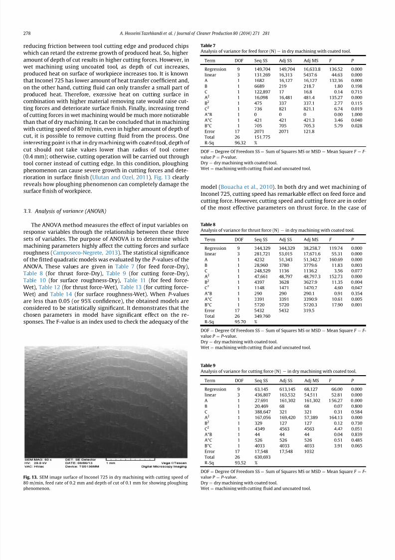
7212019 Journal of Cleaner ProductionExperimental Investigation On
httpslidepdfcomreaderfulljournal-of-cleaner-productionexperimental-investigation-on 811
reducing friction between tool cutting edge and produced chips
which can retard the extreme growth of produced heat So higher
amount of depth of cut results in higher cutting forces However in
wet machining using uncoated tool as depth of cut increases
produced heat on surface of workpiece increases too It is known
that Inconel 725 has lower amount of heat transfer coef 1047297cient and
on the other hand cutting 1047298uid can only transfer a small part of
produced heat Therefore excessive heat on cutting surface in
combination with higher material removing rate would raise cut-
ting forces and deteriorate surface 1047297nish Finally increasing trend
of cutting forces in wet machining would be much more noticeable
than that of dry machining It can be concluded that in machining
with cutting speed of 80 mmin even in higher amount of depth of
cut it is possible to remove cutting 1047298uid from the process One
interesting point is that in dry machining with coated tool depth of
cut should not take values lower than radius of tool corner
(04 mm) otherwise cutting operation will be carried out through
tool corner instead of cutting edge In this condition ploughing
phenomenon can cause severe growth in cutting forces and dete-
rioration in surface 1047297nish (Ulutan and Ozel 2011) Fig 13 clearly
reveals how ploughing phenomenon can completely damage the
surface 1047297nish of workpiece
33 Analysis of variance (ANOVA)
The ANOVA method measures the effect of input variables on
response variables through the relationship between these three
sets of variables The purpose of ANOVA is to determine which
machining parameters highly affect the cutting forces and surface
roughness (Camposeco-Negrete 2013) The statistical signi1047297cance
of the 1047297tted quadratic models was evaluated by the P -values of the
ANOVA These values are given in Table 7 (for feed force-Dry)
Table 8 (for thrust force-Dry) Table 9 (for cutting force-Dry)
Table 10 (for surface roughness-Dry) Table 11 (for feed force-
Wet) Table 12 (for thrust force-Wet) Table 13 (for cutting force-
Wet) and Table 14 (for surface roughness-Wet) When P -valuesare less than 005 (or 95 con1047297dence) the obtained models are
considered to be statistically signi1047297cant It demonstrates that the
chosen parameters in model have signi1047297cant effect on the re-
sponses The F-value is an index used to check the adequacy of the
model (Bouacha et al 2010) In both dry and wet machining of
Inconel 725 cutting speed has remarkable effect on feed force andcutting force However cutting speed and cutting force are in order
of the most effective parameters on thrust force In the case of
Table 7
Analysis of variance for feed force (N) e in dry machining with coated tool
Term DOF Seq SS Adj SS Adj MS F P
Regression 9 149704 149704 166338 13652 0000
linear 3 131269 16313 54376 4463 0000
A 1 1682 16127 16127 13236 0000
B 1 6689 219 2187 180 0198
C 1 122897 17 168 014 0715
A2
1 16098 16481 4814 13527 0000B2 1 475 337 3371 277 0115
C2 1 736 821 8211 674 0019
AB 1 0 0 0 000 1000
AC 1 421 421 4213 346 0040
BC 1 705 705 7053 579 0028
Error 17 2071 2071 1218
Total 26 151775
R-Sq 9632
DOF frac14 Degree Of Freedom SS frac14 Sum of Squares MS or MSD frac14 Mean Square F frac14 F -
value P frac14 P -value
Dry frac14 dry machining with coated tool
Wet frac14 machining with cutting 1047298uid and uncoated tool
Table 8
Analysis of variance for thrust force (N) e in dry machining with coated tool
Term DOF Seq SS Adj SS Adj MS F P
Regression 9 344329 344329 382587 11974 0000
linear 3 281721 53015 176716 5531 0000
A 1 4232 51343 513427 16069 0000
B 1 28960 3780 37796 1183 0003
C 1 248529 1136 11362 356 0077
A2 1 47661 48797 487973 15273 0000
B2 1 4397 3628 36279 1135 0004
C2 1 1148 1471 14707 460 0047
AB 1 290 290 2901 091 0354AC 1 3391 3391 33909 1061 0005
BC 1 5720 5720 57203 1790 0001
Error 17 5432 5432 3195
Total 26 349760
R-Sq 9570
DOF frac14 Degree Of Freedom SS frac14 Sum of Squares MS or MSD frac14 Mean Square F frac14 F -
value P frac14 P -value
Dry frac14 dry machining with coated tool
Wet frac14 machining with cutting 1047298uid and uncoated tool
Table 9
Analysis of variance for cutting force (N) e in dry machining with coated tool
Term DOF Seq SS Adj SS Adj MS F P
Regression 9 63145 613145 68127 6600 0000
linear 3 436807 163532 54511 5281 0000
A 1 27691 161302 161302 1 5627 0 000
B 1 20469 68 68 007 0800
C 1 388647 321 321 031 0584
A2 1 167056 169420 57389 16413 0000
B2 1 329 127 127 012 0730
C2 1 4349 4563 4563 442 0051
AB 1 44 44 44 004 0839
AC 1 526 526 526 051 0485
BC 1 4033 4033 4033 391 0065
Error 17 17548 17548 1032
Total 26 630693
R-Sq 9352
DOF frac14 Degree Of Freedom SS frac14 Sum of Squares MS or MSD frac14 Mean Square F frac14 F -
value P frac14 P -value
Dry frac14 dry machining with coated tool
Wetfrac14
machining with cutting 1047298
uid and uncoated tool
Fig 13 SEM image surface of Inconel 725 in dry machining with cutting speed of
80 mmin feed rate of 02 mm and depth of cut of 01 mm for showing ploughing
phenomenon
A Hosseini Tazehkandi et al Journal of Cleaner Production 80 (2014) 271e 281278
7212019 Journal of Cleaner ProductionExperimental Investigation On
httpslidepdfcomreaderfulljournal-of-cleaner-productionexperimental-investigation-on 911
surface 1047297nish these parameters are cutting and feed force The
effectiveness of the models for feed force thrust force cutting force
and surface roughness can be further analyzed with help of the R-
Sq values A higher value of R-Sq is always desirable
34 Regression equations
The relationship between the factors and performance mea-surements were modeled by quartic regression Using these
equations it is possible to achieve the values of machining force
components and surface roughness in both wet and dry conditions
It should be noted that the amount of input parameters needs to be
within the selected ranges As it is presented in ANOVA
Tables 7e14 the parameters with P values less than 005 have less
impact on results of experiments However in order to achieve the
maximum precision and minimum possible error in regression
models 1 to 8 even effect of the less effective machining parame-
ters and counter-effect of them have been taken into account The
cutting parameters of cutting speed feed rate and depth of cut are
represented by symbols of A B and C respectively The obtained
regression equations were as follows
Thefeed force in drymachining model (F a)isgivenbelowinEq (1)
F afrac1410846219Athorn01A2thorn737C2
thorn07ACthorn3833BC (1)
The thrust force in dry machining model (F r ) is given by Eq (2)
F r frac14 2099 391A 3431B thorn 02A2thorn 98893B2
thorn 987C2
thorn 22ACthorn 10916BC (2)
The cutting force model in dry machining (F c ) is given by Eq (3)
Table 10
Analysisof Variance for Surface roughness(mm) ein dry machining withcoated tool
Term DOF Seq SS Adj SS Adj MS F P
Regression 9 119808 116808 0133120 27633 0000
linear 3 063877 057267 0190890 39625 0000
A 1 016056 049409 0494090 102564 0000
B 1 047694 003425 0034255 7111 0000
C 1 000128 000066 0000657 136 0259
A2
1 054101 053815 0538149 11171 0000B2 1 001251 001190 0011905 2471 0000
C2 1 000056 000057 0000566 118 0293
AB 1 000521 000521 0005208 1081 0004
AC 1 000002 000002 0000015 003 00861
BC 1 000001 000001 0000008 002 0897
Error 17 000819 000819 0000482
Total 26 120627
R-Sq 9832
DOF frac14 Degree Of Freedom SS frac14 Sum of Squares MS or MSD frac14 Mean Square F frac14 F -
value P frac14 P -value
Dry frac14 dry machining with coated tool
Wet frac14 machining with cutting 1047298uid and uncoated tool
Table 11
Analysis of variance for feed force (N) e in wet machining with uncoated tool
Term DOF Seq SS Adj SS Adj MS F P
Regression 9 138468 138468 15385 12069 0000
linear 3 134374 2302 7673 602 0005
A 1 1721 2163 2163 1697 0001
B 1 7240 248 2479 194 0181
C 1 125413 14 135 011 0749
A2 1 1719 1853 1853 787 0001
B2 1 520 377 377 296 0104
C2 1 687 772 772 606 0025
AB 1 0 0 03 000 0960
AC 1 447 447 4466 350 0079
BC 1 721 721 7207 565 0029
Error 17 2167 2167 1275
Total 26 140635
R-Sq 9573
DOF frac14 Degree Of Freedom SS frac14 Sum of Squares MS or MSD frac14 Mean Square F frac14 F -value P frac14 P -value
Dry frac14 dry machining with coated tool
Wet frac14 machining with cutting 1047298uid and uncoated tool
Table 12
Analysis of variance for thrust force (N) e in wet machining with uncoated tool
Term DOF Seq SS Adj SS Adj MS F P
Regression 9 308682 308682 34298 13107 0000
linear 3 290198 9127 30422 1163 0000
A 1 4418 5515 55152 2108 0000
B 1 31920 3758 37577 1436 0001
C 1 253860 1174 11738 449 0049
A2 1 3278 3608 36078 1379 0002
B2 1 4458 3677 36772 1405 0002
C2 1 1212 1539 15391 588 0027
AB 1 280 280 2803 107 0315
AC 1 3314 3314 33142 1267 0002
BC 1 5941 5941 59407 2270 0000
Error 17 4448 4448 2617
Total 26 313131
R-Sq 9598
DOF frac14 Degree Of Freedom SS frac14 Sum of Squares MS or MSD frac14 Mean Square F frac14 F -
value P frac14 P -value
Dry frac14 dry machining with coated tool
Wetfrac14
machining with cutting 1047298
uid and uncoated tool
Table 13
Analysis of variance for cutting force (N) e in wet machining with uncoated tool
Term DOF Seq SS Adj SS Adj MS F P
Regression 9 489771 489771 54419 5245 0000
linear 3 452132 30067 100223 966 0001
A 1 28691 29954 299538 2887 0000
B 1 23545 36 361 003 0854
C 1 400897 401 4007 039 0543
A2
1 27855 28876 289763 2793 0000B2 1 284 95 945 009 0766
C2 1 4817 5040 50402 486 0042
AB 1 48 4684 15612 005 0832
AC 1 529 48 480 051 0485
BC 1 4107 529 5285 396 0063
Error 17 17638 4107 41070
Total 26 507409 17638 10375
R-Sq 9173
DOF frac14 Degree Of Freedom SS frac14 Sum of Squares MS or MSD frac14 Mean Square F frac14 F -
value P frac14 P -value
Dry frac14 dry machining with coated tool
Wet frac14 machining with cutting 1047298uid and uncoated tool
Table 14
Analysis of variance for surface roughness (mm) e in wet machining with uncoated
tool
Term DOF Seq SS Adj SS Adj MS F P
Regression 9 0759871 0759871 0084430 17641 0000
linear 3 0605476 0185149 0061716 12895 0000
A 1 0131756 0126925 0126925 26521 0000
B 1 0473689 0040946 0040946 8555 0000
C 1 0000031 0000004 0000004 001 0930
A2 1 0131131 0130791 0130791 27328 0000
B2 1 0018641 0018406 0018406 3846 0000
C2 1 0000291 0000225 0000225 047 0502
AB 1 0003675 0003675 0003675 768 0013
AC 1 0000649 0000649 0000649 136 0260
BC 1 00000080 0000008 0000008 002 0897
Error 17 0008136 0008136 0000479
Total 26 0768007
R-Sq 9825
DOF frac14 Degree Of Freedom SS frac14 Sum of Squares MS or MSD frac14 Mean Square F frac14 F -
value P frac14 P -value
Dry frac14 dry machining with coated tool
Wetfrac14
machining with cutting 1047298
uid and uncoated tool
A Hosseini Tazehkandi et al Journal of Cleaner Production 80 (2014) 271e 281 279
7212019 Journal of Cleaner ProductionExperimental Investigation On
httpslidepdfcomreaderfulljournal-of-cleaner-productionexperimental-investigation-on 1011
F c frac14 32808 694Athorn 04A2thorn 1738C2 (3)
The surface roughness model in dry machining (Ra) is given by
Eq (4)
Ra frac14 47 01Athorn 103Bthorn 00007A2 179B2
002AB (4)
The feed force in wet machining model (F a) is given below in Eq
(5)
F a frac14 5349 81Athorn 004A2thorn 715C2
thorn 3875BC (5)
The thrust force in wet machining model (F r ) is given by Eq (6)
F r frac14 10508 128A 342B 195C thorn 006A2thorn 9956B2
thorn 101C2thorn 22ACthorn 11125BC (6)
The cutting force model in wet machining (F c ) is given byEq (7)
F c frac14 1699 30Athorn 02A2thorn 1826C2 (7)
The surface roughness model in wet machining (Ra) is given by
Eq (8)
Ra frac14 23 006Athorn 113Bthorn 00004A2 22B2 002AB (8)
35 Optimization of cutting conditions
It was assumed that the optimal manufacturing conditions for
turning of Inconel 725 without cutting 1047298uid are those with mini-
mum values of cutting forces (F a F r and F c ) and surface roughness
(Ra) during the turning process It is worth noting that although
main aim of this research is removing cutting 1047298uid from machining
process some operating condition make it mandatory to utilize
cutting 1047298uid So additional study has been presented to optimizing
consumption of cutting 1047298uid during wet machining of Inconel 725
The objective of optimizing the turning process of Inconel 725
with and without cutting 1047298uid is to achieve the minimum possiblelevel of machining force components and maximum level of surface
1047297nish Therefore the optimization has been carried out with taking
the attainment of minimum cutting feed and thrust forces and
maximum surface 1047297nish into account The experiments are also
conducted practically using the provided numbers for the param-
eters A (cutting speed) B (feed rate) and C (depth of cut) in both dry
and wet machining conditions by Minitab software in order to
demonstrate the differences between the values of predicted re-
sponses and the experimental values The results of RSM procedure
have been validated using the output of experiments and it was
con1047297rmed that value of error in RSM method in dry and wet con-
ditions is less than 5 percent Table 15 and Table 16 show the RSM
optimization results for cutting forces and surface roughness in dry
and wet machining
4 Conclusion
In this study effects of process parameters (which include
cutting speed feed rate and depth of cut) and tool coating on
machining forces and surface roughness were investigated in both
dry and wet machining of nickel-based superalloy Inconel 725 in
order to remove the cutting 1047298uid and meet environmental de-
mands Considering environmental problems Biodegradablevegetable oil was utilized as cutting 1047298uid in wet machining All
experiments were carried out in full factorial method and they
were analyzed using RSM and ANOVA methods Finally optimized
parameters were achieved for both dry and wet machining The
foremost conclusions which can be drawn are as follows
Removal of cutting 1047298uid in the above-mentioned conditions
result in reduced production costs and 1047298uid production ex-
penses This in turn reduces costs of removing it from the ma-
chine and the parts and eliminates destructive effect of these
1047298uids on the environment and human health
The role of tool coating in reduction of cutting forces and
improving surface 1047297nish is much more effective than using
cutting 1047298uid Since Inconel 725 is one of the dif 1047297cult-to-cut
materials excessive heat was produced during turning and
remained on workpiece surface due to low heat transfer ca-
pacity of cutting 1047298uid However coating of tool reduced friction
and as a result made it possible to remove the cutting 1047298uid
When Inconel 725 was machined with cutting speed of 80 m
min regardless of the values of feed rate and depth of cut it was
quite feasible to eliminated cutting 1047298uid from turning process
In order to reach to the aim of successfully removing cutting
1047298uids from wet and dry machining cutting speed should not
exceed 80 mmin because it induced higher cutting forces and
deteriorated surface 1047297nish
Excessive increase of cutting speed could damage tool coating
and make it practically impossible to remove cutting 1047298uid
There was a general trend of increasing cutting forces and sur-
face roughness as feed rate and depth of cut increase
References
Aouici H Yallese MA Chaoui K Mabrouki T Rigal J-F 2012 Analysis of sur-face roughness and cutting force components in hard turning with CBN toolprediction model and cutting conditions optimization Measurement 45344e353
Bouacha K Yallese MA Mabrouki T Rigal J-F 2010 Statistical analysis of sur-face roughness and cutting forces using response surface methodology in hardturning of AISI 52100 bearing steel with CBN tool Int J Refract Metals HardMater 28 349e361
Camposeco-Negrete C 2013 Optimization of cutting parameters for minimizingenergy consumption in turning of AISI 6061 T6 using Taguchi methodology andANOVA J Clean Prod 53 195e203
Davim JP 2013 Green Manufacturing Processes and Systems Springer London
UK
Table 15
The improved values for dry machining of Inconel 725
Cutting speed
(mmin)
Feed rate
(mmrev)
Depth of
cut (mm)
Feed force (N) Thrust force (N) Cutting force (N) Surface roughness
(mm)
Error
Predicted values 822 01 04 15834 25727 42801 0492 5
Experimental values 822 01 04 16413 26922 44179 051 e
Table 16
The improved values for wet machining of Inconel 725
Cutting speed
(mmin)
Feed rate
(mmrev)
Depth of
cut (mm)
Feed force (N) Thrust force (N) Cutting force (N) Surface roughness
(mm)
Error
Predicted values 896 01 04 1604 2567 43045 051 5
Experimental values 896 01 04 16729 2669 45240 054 e
A Hosseini Tazehkandi et al Journal of Cleaner Production 80 (2014) 271e 281280
7212019 Journal of Cleaner ProductionExperimental Investigation On
httpslidepdfcomreaderfulljournal-of-cleaner-productionexperimental-investigation-on 1111
Davoodi B Tazehkandi AH 2014 Experimental investigation and optimization of cutting parameters in dry and wet machining of aluminum alloy 5083 in orderto remove cutting 1047298uid J Clean Prod 68 234e242 httpdxdoiorg101016
jjclepro201312056Devillez A Le Coz G Dominiak S Dudzinski D 2011 Dry machining of Inconel
718 workpiece surface integrity J Mater Process Technol 211 1590e1598Ezilarasan C Velayudham A January 2013 An experimental analysis and
measurement of process performances in machining of nimonic C-263super alloy Measurement 46 (1) 185e199 httpdxdoiorg101016
jmeasurement201206006
Fratila D Caizar C 2011 Application of Taguchi method to selection of optimallubrication and cutting conditions in face milling of AlMg 3 J Clean Prod 19640e645
Groover MP 2007 Fundamentals of Modern Manufacturing Materials Processesand Systems Wiley com United States of America
Kuram E Ozcelik B Bayramoglu M Demirbas E Simsek BT 2012 Optimizationof cutting 1047298uids and cutting parameters during end milling by using D-optimaldesign of experiments J Clean Prod
Kuram E Ozcelik B Demirbas E 2013 Environmentally Friendly MachiningVegetable Based Cutting Fluids Green Manufacturing Processes and SystemsSpringer pp 23e47
Lalwani D Mehta N Jain P 2008 Experimental investigations of cutting pa-rameters in1047298uence on cutting forces and surface roughness in 1047297nish hardturning of MDN250 steel J Mater Process Technol 206 167e179
Lawal SA Choudhury IA Nukman Y 2013 A critical assessment of lubricationtechniques in machining processes a case for minimum quantity lubricationusing vegetable oil-based lubricant J Clean Prod 41 210e221
Mandal N Doloi B Mondal B Das R 2011 Optimization of 1047298ank wear usingZirconia Toughened Alumina (ZTA) cutting tool Taguchi method and Regres-sion analysis Measurement 44 2149e2155
Nalbant M Altın A Geurookkaya H 2007 The effect of cutting speed and cutting toolgeometry on machinability properties of nickel-base Inconel 718 super alloysMater Des 28 1334e1338
Sarıkaya M Guumllluuml A 2014 Taguchi design and response surface methodology
based analysis of machining parameters in CNC turning under MQL J CleanProd 65 604e616
Settineri L Faga MG Lerga B 2008 Properties and performances of innovativecoated tools for turning inconel Int J Mach Tools Manuf 48 815e823
Ulutan D Ozel T 2011 Machining induced surface integrity in titanium and nickelalloys a review Int J Mach Tools Manuf 51 250e280
Weinert K Inasaki I Sutherland J Wakabayashi T 2004 Dry machining andminimum quantity lubrication CIRP Ann Manuf Techn 53 511e537
Zhang S Li J Wang Y 2012 Tool life and cutting forces in end milling Inconel 718under dry and minimum quantity cooling lubrication cutting conditions
J Clean Prod 32 81e87ZouB ChenM Huang CAnQ 2009 Studyon surface damages causedby turning
NiCr20TiAl nickel-based alloy J Mater Process Technol 209 5802e5809
A Hosseini Tazehkandi et al Journal of Cleaner Production 80 (2014) 271e 281 281
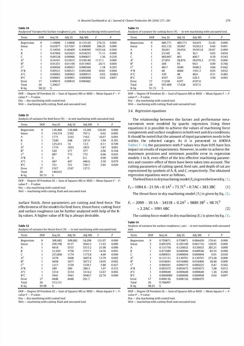
7212019 Journal of Cleaner ProductionExperimental Investigation On
httpslidepdfcomreaderfulljournal-of-cleaner-productionexperimental-investigation-on 911
surface 1047297nish these parameters are cutting and feed force The
effectiveness of the models for feed force thrust force cutting force
and surface roughness can be further analyzed with help of the R-
Sq values A higher value of R-Sq is always desirable
34 Regression equations
The relationship between the factors and performance mea-surements were modeled by quartic regression Using these
equations it is possible to achieve the values of machining force
components and surface roughness in both wet and dry conditions
It should be noted that the amount of input parameters needs to be
within the selected ranges As it is presented in ANOVA
Tables 7e14 the parameters with P values less than 005 have less
impact on results of experiments However in order to achieve the
maximum precision and minimum possible error in regression
models 1 to 8 even effect of the less effective machining parame-
ters and counter-effect of them have been taken into account The
cutting parameters of cutting speed feed rate and depth of cut are
represented by symbols of A B and C respectively The obtained
regression equations were as follows
Thefeed force in drymachining model (F a)isgivenbelowinEq (1)
F afrac1410846219Athorn01A2thorn737C2
thorn07ACthorn3833BC (1)
The thrust force in dry machining model (F r ) is given by Eq (2)
F r frac14 2099 391A 3431B thorn 02A2thorn 98893B2
thorn 987C2
thorn 22ACthorn 10916BC (2)
The cutting force model in dry machining (F c ) is given by Eq (3)
Table 10
Analysisof Variance for Surface roughness(mm) ein dry machining withcoated tool
Term DOF Seq SS Adj SS Adj MS F P
Regression 9 119808 116808 0133120 27633 0000
linear 3 063877 057267 0190890 39625 0000
A 1 016056 049409 0494090 102564 0000
B 1 047694 003425 0034255 7111 0000
C 1 000128 000066 0000657 136 0259
A2
1 054101 053815 0538149 11171 0000B2 1 001251 001190 0011905 2471 0000
C2 1 000056 000057 0000566 118 0293
AB 1 000521 000521 0005208 1081 0004
AC 1 000002 000002 0000015 003 00861
BC 1 000001 000001 0000008 002 0897
Error 17 000819 000819 0000482
Total 26 120627
R-Sq 9832
DOF frac14 Degree Of Freedom SS frac14 Sum of Squares MS or MSD frac14 Mean Square F frac14 F -
value P frac14 P -value
Dry frac14 dry machining with coated tool
Wet frac14 machining with cutting 1047298uid and uncoated tool
Table 11
Analysis of variance for feed force (N) e in wet machining with uncoated tool
Term DOF Seq SS Adj SS Adj MS F P
Regression 9 138468 138468 15385 12069 0000
linear 3 134374 2302 7673 602 0005
A 1 1721 2163 2163 1697 0001
B 1 7240 248 2479 194 0181
C 1 125413 14 135 011 0749
A2 1 1719 1853 1853 787 0001
B2 1 520 377 377 296 0104
C2 1 687 772 772 606 0025
AB 1 0 0 03 000 0960
AC 1 447 447 4466 350 0079
BC 1 721 721 7207 565 0029
Error 17 2167 2167 1275
Total 26 140635
R-Sq 9573
DOF frac14 Degree Of Freedom SS frac14 Sum of Squares MS or MSD frac14 Mean Square F frac14 F -value P frac14 P -value
Dry frac14 dry machining with coated tool
Wet frac14 machining with cutting 1047298uid and uncoated tool
Table 12
Analysis of variance for thrust force (N) e in wet machining with uncoated tool
Term DOF Seq SS Adj SS Adj MS F P
Regression 9 308682 308682 34298 13107 0000
linear 3 290198 9127 30422 1163 0000
A 1 4418 5515 55152 2108 0000
B 1 31920 3758 37577 1436 0001
C 1 253860 1174 11738 449 0049
A2 1 3278 3608 36078 1379 0002
B2 1 4458 3677 36772 1405 0002
C2 1 1212 1539 15391 588 0027
AB 1 280 280 2803 107 0315
AC 1 3314 3314 33142 1267 0002
BC 1 5941 5941 59407 2270 0000
Error 17 4448 4448 2617
Total 26 313131
R-Sq 9598
DOF frac14 Degree Of Freedom SS frac14 Sum of Squares MS or MSD frac14 Mean Square F frac14 F -
value P frac14 P -value
Dry frac14 dry machining with coated tool
Wetfrac14
machining with cutting 1047298
uid and uncoated tool
Table 13
Analysis of variance for cutting force (N) e in wet machining with uncoated tool
Term DOF Seq SS Adj SS Adj MS F P
Regression 9 489771 489771 54419 5245 0000
linear 3 452132 30067 100223 966 0001
A 1 28691 29954 299538 2887 0000
B 1 23545 36 361 003 0854
C 1 400897 401 4007 039 0543
A2
1 27855 28876 289763 2793 0000B2 1 284 95 945 009 0766
C2 1 4817 5040 50402 486 0042
AB 1 48 4684 15612 005 0832
AC 1 529 48 480 051 0485
BC 1 4107 529 5285 396 0063
Error 17 17638 4107 41070
Total 26 507409 17638 10375
R-Sq 9173
DOF frac14 Degree Of Freedom SS frac14 Sum of Squares MS or MSD frac14 Mean Square F frac14 F -
value P frac14 P -value
Dry frac14 dry machining with coated tool
Wet frac14 machining with cutting 1047298uid and uncoated tool
Table 14
Analysis of variance for surface roughness (mm) e in wet machining with uncoated
tool
Term DOF Seq SS Adj SS Adj MS F P
Regression 9 0759871 0759871 0084430 17641 0000
linear 3 0605476 0185149 0061716 12895 0000
A 1 0131756 0126925 0126925 26521 0000
B 1 0473689 0040946 0040946 8555 0000
C 1 0000031 0000004 0000004 001 0930
A2 1 0131131 0130791 0130791 27328 0000
B2 1 0018641 0018406 0018406 3846 0000
C2 1 0000291 0000225 0000225 047 0502
AB 1 0003675 0003675 0003675 768 0013
AC 1 0000649 0000649 0000649 136 0260
BC 1 00000080 0000008 0000008 002 0897
Error 17 0008136 0008136 0000479
Total 26 0768007
R-Sq 9825
DOF frac14 Degree Of Freedom SS frac14 Sum of Squares MS or MSD frac14 Mean Square F frac14 F -
value P frac14 P -value
Dry frac14 dry machining with coated tool
Wetfrac14
machining with cutting 1047298
uid and uncoated tool
A Hosseini Tazehkandi et al Journal of Cleaner Production 80 (2014) 271e 281 279
7212019 Journal of Cleaner ProductionExperimental Investigation On
httpslidepdfcomreaderfulljournal-of-cleaner-productionexperimental-investigation-on 1011
F c frac14 32808 694Athorn 04A2thorn 1738C2 (3)
The surface roughness model in dry machining (Ra) is given by
Eq (4)
Ra frac14 47 01Athorn 103Bthorn 00007A2 179B2
002AB (4)
The feed force in wet machining model (F a) is given below in Eq
(5)
F a frac14 5349 81Athorn 004A2thorn 715C2
thorn 3875BC (5)
The thrust force in wet machining model (F r ) is given by Eq (6)
F r frac14 10508 128A 342B 195C thorn 006A2thorn 9956B2
thorn 101C2thorn 22ACthorn 11125BC (6)
The cutting force model in wet machining (F c ) is given byEq (7)
F c frac14 1699 30Athorn 02A2thorn 1826C2 (7)
The surface roughness model in wet machining (Ra) is given by
Eq (8)
Ra frac14 23 006Athorn 113Bthorn 00004A2 22B2 002AB (8)
35 Optimization of cutting conditions
It was assumed that the optimal manufacturing conditions for
turning of Inconel 725 without cutting 1047298uid are those with mini-
mum values of cutting forces (F a F r and F c ) and surface roughness
(Ra) during the turning process It is worth noting that although
main aim of this research is removing cutting 1047298uid from machining
process some operating condition make it mandatory to utilize
cutting 1047298uid So additional study has been presented to optimizing
consumption of cutting 1047298uid during wet machining of Inconel 725
The objective of optimizing the turning process of Inconel 725
with and without cutting 1047298uid is to achieve the minimum possiblelevel of machining force components and maximum level of surface
1047297nish Therefore the optimization has been carried out with taking
the attainment of minimum cutting feed and thrust forces and
maximum surface 1047297nish into account The experiments are also
conducted practically using the provided numbers for the param-
eters A (cutting speed) B (feed rate) and C (depth of cut) in both dry
and wet machining conditions by Minitab software in order to
demonstrate the differences between the values of predicted re-
sponses and the experimental values The results of RSM procedure
have been validated using the output of experiments and it was
con1047297rmed that value of error in RSM method in dry and wet con-
ditions is less than 5 percent Table 15 and Table 16 show the RSM
optimization results for cutting forces and surface roughness in dry
and wet machining
4 Conclusion
In this study effects of process parameters (which include
cutting speed feed rate and depth of cut) and tool coating on
machining forces and surface roughness were investigated in both
dry and wet machining of nickel-based superalloy Inconel 725 in
order to remove the cutting 1047298uid and meet environmental de-
mands Considering environmental problems Biodegradablevegetable oil was utilized as cutting 1047298uid in wet machining All
experiments were carried out in full factorial method and they
were analyzed using RSM and ANOVA methods Finally optimized
parameters were achieved for both dry and wet machining The
foremost conclusions which can be drawn are as follows
Removal of cutting 1047298uid in the above-mentioned conditions
result in reduced production costs and 1047298uid production ex-
penses This in turn reduces costs of removing it from the ma-
chine and the parts and eliminates destructive effect of these
1047298uids on the environment and human health
The role of tool coating in reduction of cutting forces and
improving surface 1047297nish is much more effective than using
cutting 1047298uid Since Inconel 725 is one of the dif 1047297cult-to-cut
materials excessive heat was produced during turning and
remained on workpiece surface due to low heat transfer ca-
pacity of cutting 1047298uid However coating of tool reduced friction
and as a result made it possible to remove the cutting 1047298uid
When Inconel 725 was machined with cutting speed of 80 m
min regardless of the values of feed rate and depth of cut it was
quite feasible to eliminated cutting 1047298uid from turning process
In order to reach to the aim of successfully removing cutting
1047298uids from wet and dry machining cutting speed should not
exceed 80 mmin because it induced higher cutting forces and
deteriorated surface 1047297nish
Excessive increase of cutting speed could damage tool coating
and make it practically impossible to remove cutting 1047298uid
There was a general trend of increasing cutting forces and sur-
face roughness as feed rate and depth of cut increase
References
Aouici H Yallese MA Chaoui K Mabrouki T Rigal J-F 2012 Analysis of sur-face roughness and cutting force components in hard turning with CBN toolprediction model and cutting conditions optimization Measurement 45344e353
Bouacha K Yallese MA Mabrouki T Rigal J-F 2010 Statistical analysis of sur-face roughness and cutting forces using response surface methodology in hardturning of AISI 52100 bearing steel with CBN tool Int J Refract Metals HardMater 28 349e361
Camposeco-Negrete C 2013 Optimization of cutting parameters for minimizingenergy consumption in turning of AISI 6061 T6 using Taguchi methodology andANOVA J Clean Prod 53 195e203
Davim JP 2013 Green Manufacturing Processes and Systems Springer London
UK
Table 15
The improved values for dry machining of Inconel 725
Cutting speed
(mmin)
Feed rate
(mmrev)
Depth of
cut (mm)
Feed force (N) Thrust force (N) Cutting force (N) Surface roughness
(mm)
Error
Predicted values 822 01 04 15834 25727 42801 0492 5
Experimental values 822 01 04 16413 26922 44179 051 e
Table 16
The improved values for wet machining of Inconel 725
Cutting speed
(mmin)
Feed rate
(mmrev)
Depth of
cut (mm)
Feed force (N) Thrust force (N) Cutting force (N) Surface roughness
(mm)
Error
Predicted values 896 01 04 1604 2567 43045 051 5
Experimental values 896 01 04 16729 2669 45240 054 e
A Hosseini Tazehkandi et al Journal of Cleaner Production 80 (2014) 271e 281280
7212019 Journal of Cleaner ProductionExperimental Investigation On
httpslidepdfcomreaderfulljournal-of-cleaner-productionexperimental-investigation-on 1111
Davoodi B Tazehkandi AH 2014 Experimental investigation and optimization of cutting parameters in dry and wet machining of aluminum alloy 5083 in orderto remove cutting 1047298uid J Clean Prod 68 234e242 httpdxdoiorg101016
jjclepro201312056Devillez A Le Coz G Dominiak S Dudzinski D 2011 Dry machining of Inconel
718 workpiece surface integrity J Mater Process Technol 211 1590e1598Ezilarasan C Velayudham A January 2013 An experimental analysis and
measurement of process performances in machining of nimonic C-263super alloy Measurement 46 (1) 185e199 httpdxdoiorg101016
jmeasurement201206006
Fratila D Caizar C 2011 Application of Taguchi method to selection of optimallubrication and cutting conditions in face milling of AlMg 3 J Clean Prod 19640e645
Groover MP 2007 Fundamentals of Modern Manufacturing Materials Processesand Systems Wiley com United States of America
Kuram E Ozcelik B Bayramoglu M Demirbas E Simsek BT 2012 Optimizationof cutting 1047298uids and cutting parameters during end milling by using D-optimaldesign of experiments J Clean Prod
Kuram E Ozcelik B Demirbas E 2013 Environmentally Friendly MachiningVegetable Based Cutting Fluids Green Manufacturing Processes and SystemsSpringer pp 23e47
Lalwani D Mehta N Jain P 2008 Experimental investigations of cutting pa-rameters in1047298uence on cutting forces and surface roughness in 1047297nish hardturning of MDN250 steel J Mater Process Technol 206 167e179
Lawal SA Choudhury IA Nukman Y 2013 A critical assessment of lubricationtechniques in machining processes a case for minimum quantity lubricationusing vegetable oil-based lubricant J Clean Prod 41 210e221
Mandal N Doloi B Mondal B Das R 2011 Optimization of 1047298ank wear usingZirconia Toughened Alumina (ZTA) cutting tool Taguchi method and Regres-sion analysis Measurement 44 2149e2155
Nalbant M Altın A Geurookkaya H 2007 The effect of cutting speed and cutting toolgeometry on machinability properties of nickel-base Inconel 718 super alloysMater Des 28 1334e1338
Sarıkaya M Guumllluuml A 2014 Taguchi design and response surface methodology
based analysis of machining parameters in CNC turning under MQL J CleanProd 65 604e616
Settineri L Faga MG Lerga B 2008 Properties and performances of innovativecoated tools for turning inconel Int J Mach Tools Manuf 48 815e823
Ulutan D Ozel T 2011 Machining induced surface integrity in titanium and nickelalloys a review Int J Mach Tools Manuf 51 250e280
Weinert K Inasaki I Sutherland J Wakabayashi T 2004 Dry machining andminimum quantity lubrication CIRP Ann Manuf Techn 53 511e537
Zhang S Li J Wang Y 2012 Tool life and cutting forces in end milling Inconel 718under dry and minimum quantity cooling lubrication cutting conditions
J Clean Prod 32 81e87ZouB ChenM Huang CAnQ 2009 Studyon surface damages causedby turning
NiCr20TiAl nickel-based alloy J Mater Process Technol 209 5802e5809
A Hosseini Tazehkandi et al Journal of Cleaner Production 80 (2014) 271e 281 281
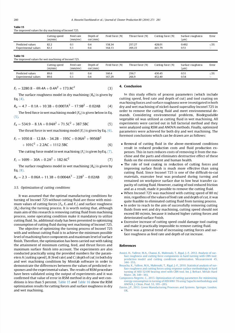
7212019 Journal of Cleaner ProductionExperimental Investigation On
httpslidepdfcomreaderfulljournal-of-cleaner-productionexperimental-investigation-on 1111
Davoodi B Tazehkandi AH 2014 Experimental investigation and optimization of cutting parameters in dry and wet machining of aluminum alloy 5083 in orderto remove cutting 1047298uid J Clean Prod 68 234e242 httpdxdoiorg101016
jjclepro201312056Devillez A Le Coz G Dominiak S Dudzinski D 2011 Dry machining of Inconel
718 workpiece surface integrity J Mater Process Technol 211 1590e1598Ezilarasan C Velayudham A January 2013 An experimental analysis and
measurement of process performances in machining of nimonic C-263super alloy Measurement 46 (1) 185e199 httpdxdoiorg101016
jmeasurement201206006
Fratila D Caizar C 2011 Application of Taguchi method to selection of optimallubrication and cutting conditions in face milling of AlMg 3 J Clean Prod 19640e645
Groover MP 2007 Fundamentals of Modern Manufacturing Materials Processesand Systems Wiley com United States of America
Kuram E Ozcelik B Bayramoglu M Demirbas E Simsek BT 2012 Optimizationof cutting 1047298uids and cutting parameters during end milling by using D-optimaldesign of experiments J Clean Prod
Kuram E Ozcelik B Demirbas E 2013 Environmentally Friendly MachiningVegetable Based Cutting Fluids Green Manufacturing Processes and SystemsSpringer pp 23e47
Lalwani D Mehta N Jain P 2008 Experimental investigations of cutting pa-rameters in1047298uence on cutting forces and surface roughness in 1047297nish hardturning of MDN250 steel J Mater Process Technol 206 167e179
Lawal SA Choudhury IA Nukman Y 2013 A critical assessment of lubricationtechniques in machining processes a case for minimum quantity lubricationusing vegetable oil-based lubricant J Clean Prod 41 210e221
Mandal N Doloi B Mondal B Das R 2011 Optimization of 1047298ank wear usingZirconia Toughened Alumina (ZTA) cutting tool Taguchi method and Regres-sion analysis Measurement 44 2149e2155
Nalbant M Altın A Geurookkaya H 2007 The effect of cutting speed and cutting toolgeometry on machinability properties of nickel-base Inconel 718 super alloysMater Des 28 1334e1338
Sarıkaya M Guumllluuml A 2014 Taguchi design and response surface methodology
based analysis of machining parameters in CNC turning under MQL J CleanProd 65 604e616
Settineri L Faga MG Lerga B 2008 Properties and performances of innovativecoated tools for turning inconel Int J Mach Tools Manuf 48 815e823
Ulutan D Ozel T 2011 Machining induced surface integrity in titanium and nickelalloys a review Int J Mach Tools Manuf 51 250e280
Weinert K Inasaki I Sutherland J Wakabayashi T 2004 Dry machining andminimum quantity lubrication CIRP Ann Manuf Techn 53 511e537
Zhang S Li J Wang Y 2012 Tool life and cutting forces in end milling Inconel 718under dry and minimum quantity cooling lubrication cutting conditions
J Clean Prod 32 81e87ZouB ChenM Huang CAnQ 2009 Studyon surface damages causedby turning
NiCr20TiAl nickel-based alloy J Mater Process Technol 209 5802e5809
A Hosseini Tazehkandi et al Journal of Cleaner Production 80 (2014) 271e 281 281