Embed Size (px)
Citation preview
Joining Sintered Steel to Wrought Steel Using Various Welding Processes
A means of evaluating weldability is described for joining pressed and sintered steel powder parts to wrought mild steel parts using various welding processes
BY J. F. H I N R I C H S , P. W. R A M S E Y , A N D M. W. Z I M M E R M A N N
ABSTRACT. The use of sintered steel parts has grown due to the economic advantages of efficient utilization of material and elimination of machining. Weldments of sintered and wrought steel parts can result in additional economic gains and improved quality, but there is a lack of knowledge on the weldability of such joints. The normal test plate approach was not considered practical because of the difficulty of compacting plates of sufficient size.
A torsion test was devised to evaluate weld joints between pressed and sintered steel powder parts and wrought steel parts. Cylinders 1 in. in diameter X 2 in. were' prepared from atomized steel powders and joined to semi-killed wrought steel plates B/1( i X 3 X 3 in.
The sintered steel compacts were varied in both carbon level (0.02%-0.8% C) and density (82-95% of theoretical density).
The six processes chosen for evaluation were gas tungsten-arc (argon), gas metal-arc (COo), nonvacuum and medium vacuum electron beam, resistance projection, and friction welding. The weld joint was modified to suit each process, and welding conditions used were considered typical, but not necessarily optimum, for each process.
The torsion specimen was then tested in a special fixture using a laboratory hydraulic tensile testing machine to determine maximum load. To provide comparative data, sintered steel cylinders mechanically connected to wrought steel plate using 1/4 X V4 in. steel keys were also tested.
Further evaluation included visual inspection, dye - penetrant, macro-sections, and DPH hardness traverses. This weldability evaluation led to the conclusion
J. F . HINRICHS is Pro jec t Engineer . P . W. RAMSEY is Manager and M. W. ZIMMERMANN is Senior Engineer a t the Welding Research & Development Labora to ry , A. O. Smith Corp. . Milwaukee, Wis.
Pape r presented at the AWS 52nd Annual Meeting held in San Francisco, Calif., during April 26-29, 1971.
that all processes investigated can be successfully used to join sintered steel to wrought mild steel, and showed significantly higher torsional load-carrying ability than mechancial key connections. It was also determined that the torsional load-carrying ability increased directly with both carbon level and density of the sintered steel. All fusion processes produced crack-free welds, based on visual and dye-penetrant examination.
Introduction Sintered steel parts are used to gain
economic advantage due to more efficient material utilization and the elimination of machining. Pressed and sintered parts generally are made in
SINTERED STEEt 1"0IA. X 2"
h>/////////J/////////4 • *
0.080'
i
SINTERED STEEL*'
t'DIA. X 2"
r
y
.58" »j
X
large quantit ies, and therefore welding processes that lend themselves to high speed product ion are of more interest than such processes as shielded metal arc welding.
Welding of sintered steel parts to wrought steel parts can result in additional economic gains and improved quality. As one example, the attachment of a gear to a shaft could be done by a high speed welding process, thereby eliminating the machining of a keyway and key.
Brazing is also used to join gears to shafts but distortion of the parts due to brazing tempera ture could cause dimensional problems. Selection of a
90* X ft DEEP GROOVE
SINTERED STEEL T'DIA. X 2"
SINTERED STEEL
T'DIA. X 2"
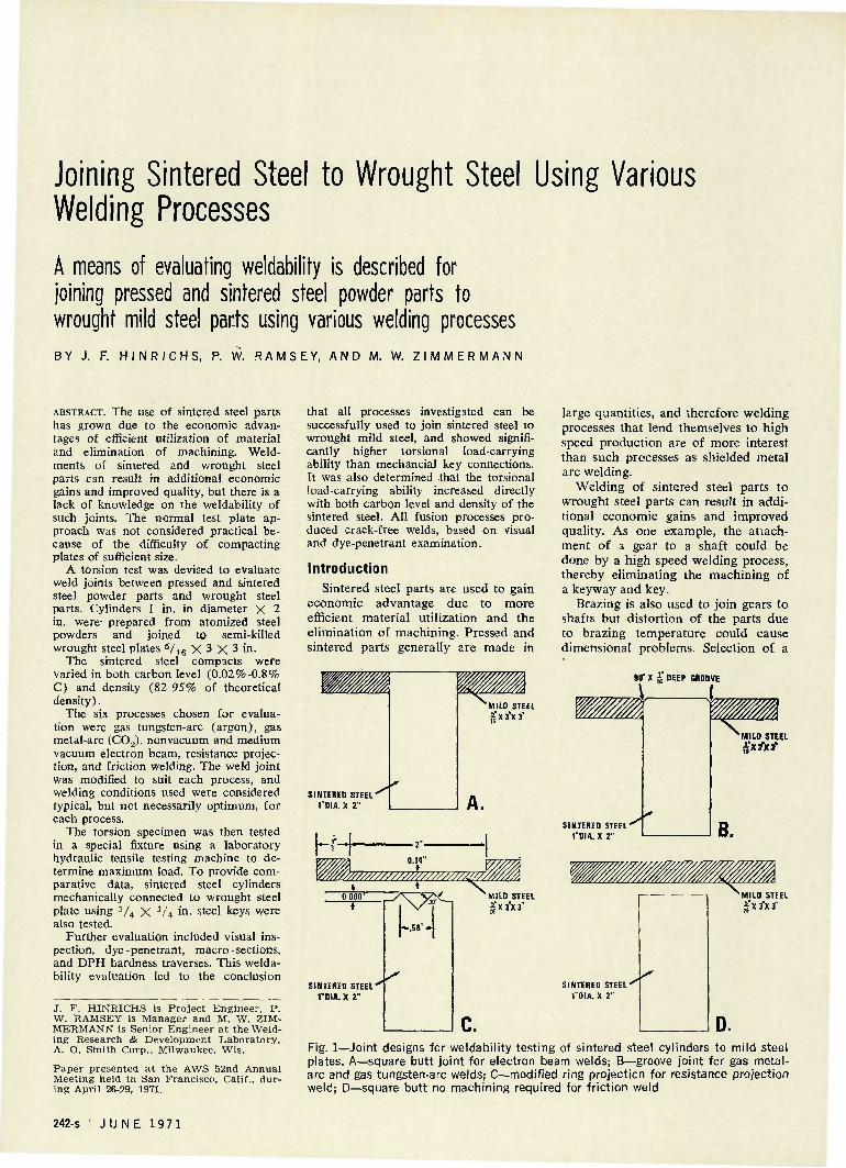
Fig. 1—Joint designs for weldability testing of sintered steel cylinders to mild steel plates. A—square butt joint for electron beam welds; B—groove joint for gas metal-arc and gas tungsten-arc welds; C—modified ring projection for resistance projection weld; D—square butt no machining required for friction weld
242-s | J U N E 1971

proper welding process could minimize this problem.
Weldability has been defined* as "the capacity of a metal to be welded, under fabrication conditions imposed, into a specific, suitably designed struc
ture, and to perform satisfactorily in the intended service." Evaluation of weldability in the case of wrought materials generally involves making a test plate with the intended service in mind, and using the desired welding
Table 1—Processes and Typical Welding Conditions for Weldability Testing of Sintered Steel to Mild Steel
Welding process
Semi-automatic gas metal-arc welding
Typical welding conditions
Power source: 300 amp constant potential
Manual gas tungsten-arc welding
Welding current: Welding voltage: Shielding gas: Travel speed: Filler metal:
Power source:
Welding current: Welding voltage: Shielding gas: Travel speed: Electrode:
Filler metal:
Medium vacuum Welding unit: electron beam vacuum welding Beam current: 15 ma
Beam voltage: 120 kv Chamber vacuum: 50 microns Travel speed: 34.5 ipm Filler metal: None
180ampd-c+ 23 v d-c 40 cfh-C02
30 ipm AWS E70S-3-.035 in. diam
300 amp a-c/d-c constant current
125 amp d-c— 13 v d-c 6 cfh-Argon 3-6 ipm 2% Thoriated tungsten y% in. diam AWS E70S-3-.045 in. diam
EB6 KW-medium & high
Type of weld joint
45 deg X He in. Deep groove (See Fig. IB)
45 deg X He, in. Deep groove (See Fig. IB)
Square butt (See Fig. 1A)
Nonvacuum electron beam welding
Resistance Projection welding
Friction welding
Welding unit: Beam current: Beam voltage: Pressure: Travel speed: Filler metal:
Welding unit: Welding current: Electrode force: Weld t ime:
Welding unit: Inertial mass: Spindle speed: Thrust force:
EB 12 KW-nonvacuum 18 ma 175 kv Atmospheric 35 ipm None
200 kva 39,000 amp a-c 4,750 lb 30 cycles.
Inertia (Caterp 68lb-ft2
2250 rpm 20,000 lb
liar Model 250)
Square butt (See Fig. 1A)
Modified Ring projection (See Fig. 1C)
Square butt No machining required. (See Fig. ID)
MILD STEEL STATIONARY PLATE
WRENCH TYPE
MILD STEEL
FIXTURE TOP CLAMP
GMAW FILLET WELD
INTERED STEEL TEST CYLINDER
FIXTURE BASE
Fig. 2—Schematic view showing a cross-section of the torsion test specimen and fixture
process. This plate is then evaluated using tensile, bend, hardness, and other metallurgical techniques as set forth in various AWS specifications and Section IX of ASME Boiler and Pressure Vessel Code. The degree of compliance of the welded joint to such codes is one measure of its weldability.
In the case of sintered parts it is not generally possible to compact test plates of sufficient size to evaluate in accordance with such specifications. In addition, sintered steel powder parts characteristically do not exhibit as much ductility as melted and rolled steel.
A more appropriate test was therefore developed which could be used with various welding processes, and by which the welded samples could be easily evaluated by mechanical and metallurgical methods.
The ease of preparing standard pressed and sintered steel parts also had to be considered inasmuch as a number of variations in composition and density were to be evaluated.
Design of Test Specimen After a review of various sintered
steel shapes that could be readily produced in the laboratory, a cylinder of approximately 1 in. diameter by 2 in. was selected. Composition of the steel powder and compacted density could be easily controlled with this cylinder.
Atomized steel powder was blended with the desired level of graphite and 0.75% zinc stearate lubricant to produce a homogeneous mixture. Composition of the powder (A. O. Smith-Inland Goode EMP-300M) is similar in composition to an AISI-1005 steel, and is nominally 0.02% C, 0.20% Mn, 0.02% Si, 0.005% P, 0.010% S. Four combined carbon levels in the mild steel powder parts were investigated, 0.02%, 0.2%, 0.4%, and 0.8% by adding 0%, 0.25%, 0.45%, and 0.85% graphite. A slight excess of graphite .was required to compensate for loss during sintering.
Sintered densities of 82%, 89%, and 95% of theoretical density for each of the four carbon levels were prepared. Calculations were based on 7.86 gm/cc, the density of iron. Compacting pressures of 25 tons/in.2 and 40 tons/in.2 were used to produce densities of 82% and 89%. To obtain 95% density the specimens were first pressed at 76 tons/in.,2 presintered in dissociated ammonia for 10 min. at 1650° F, and then repressed at 45 tons/in.2. All specimens were then sintered at 2050° F for 20 min. in a
*American Welding Society, Welding Handbook, Section 2 (6th edition) p. 56— Appendix.
W E L D I N G R E S E A R C H S U P P L E M E N T | 243-s

commercial sintering furnace using a dissociated ammonia atmosphere. For comparison purposes, wrought steel cylinders were also used to prepare test assemblies representing 100% theoretical density.
Wrought steel plates for the test specimen were 5/1G X 3 X 3 in. and had a nominal composition of 0.25% C, 1.11% Mn, 0.13% Si, 0.024% P, 0.025% S. This choice of a semi-killed mild steel provided some silicon for use as a weld deoxidizer. A small amount of deoxidizer such as silicon or aluminum is required to obtain reasonably sound welds with fusion welding processes such as medium vacuum and nonvacuum electron beam welding, where no deoxidizing filler metal was added.
Welding Procedures The joint design was varied to suit
the welding process and four weld joint designs were used as shown in Fig. 1. Each type was prepared by machining the sintered steel cylinder and the mild steel plate. Six welding processes were chosen for evaluation: gas tungsten-arc, gas metal-arc, non-vacuum electron beam, medium vacuum electron beam, resistance projection, and friction welding.
In the case of the fusion welding processes the depth of penetration was approximately 1 / 8 in., using joints as shown in Fig. 1A and IB. Modifications of the mild steel plate to accommodate a reasonable set of resistance projection welding parameters are shown in Fig. 1C. The diameter of the ring projection selected was the maximum that could be welded within the capacity of the 200 kva laboratory resistance welding machine. For friction welding a square butt joint, (Fig. ID) was satisfactory.
A summary of the typical welding condtions for the six processes used to make torsion test specimens is shown in Table 1.
In the case of the fusion welds a small rotating fixture was used to hold the test specimen and provide uniform relative motion between workpiece and welding arc or electron beam.
The resistance projection welding electrodes consisted of an upper round electrode 1 in. in diameter and a lower split electrode to grip the sintered metal cylinder within V 4 in. of the top of the ring projection.
Welding procedures were selected to produce a penetration of approximately V s in. or a reasonably comparable and satisfactory weld. The welding conditions used were judged to be practical for all processes. However, maximum welding speeds were not necessarily achieved.
Fig. 3—Effect of carbon content on porosity level of nonvacuum electron beam welds. Photographs show sintered steel cylinders (95% density)
Test welds made by the fusion welding processes were first visually inspected and then the weld bead was
ground flush with the surface of the steel plate for dye-penetrant inspection.
Extruded flash from the friction welded specimen was removed by machining. Only visual inspection was used to evaluate these welds and the resistance projection welds.
After completing the test weld, a similar sized mild steel plate, with a 1 in. hole, was fillet welded on the opposite end of the sintered steel cylinder using semi-automatic gas metal-arc welding with CO., shielding. The second plate provided a means of holding the sintered steel cylinder during torque testing, and established a fixed distance of about 1 in. between this steel plate and the plate with the test welds.
The torque testing fixture and load arm were designed for use with a laboratory hydraulic tensile testing machine. A cross sectional view of the test fixture with a specimen in place is shown in Fig. 2. The possibility of bending the test specimen was minimized by holding a close tolerance between the fixture and the steel plate. The load on the 6 in. lever arm was then slowly increased until the specimen failed in torsion.
In addition, specimens of the wrought steel plates and sintered steel cylinders were prepared with standard V4 in X V 4 in. keys and tested to provide torque data for comparison with the welded specimens.
Discussion and Results Conditions for joining each of the
four carbon levels and three densities of sintered steel to wrought steel were held essentially constant for each of the welding processes investigated. This assured that the primary variables were the composition and density of the sintered steel cylinder.
All welds made by the six processes were visually inspected and considered to be of satisfactory quality for torsion testing. Dye-penetrant inspection of all fusion welds showed no evidence of surface cracking.
Visual inspection of the weld bead surfaces in the electron beam welds did show increasing porosity as the carbon level increased. The effect of increasing carbon content in nonvacuum electron beam welds of 95% density sintered steel to wrought steel is shown in Fig. 3, and it is evident that to minimize porosity due to evolution of CO gas in the weld, the carbon content should be kept as low as possible.
Torsion test results of the welded specimens were compared to those using the standard key connections. The effect of combined carbon in the
244-s I J U N E 1 9 7 1

Q 16,000
g 14,000 X ' u z ~ 12,000
as 7 10,000
O io Q 8000
z O 6000 UJ
o
< 2000
.2 .3 .4 .5 .6 , .7
% C A R B O N IN SINTERED METAL
Fig. 4—Effect of sinte'red metal combined carbon content on torsional strength of welded specimens. (Points represent averaged values of 82, 89, and 95% density specimens)
Q 16,000
* 14,000'
z"
ac ~. 10,000
O
Q 8000
2 ***' 6000 UJ
O
g 4000
X < 2000
% OF THEORETICAL DENSITY
Fig. 5.—Effect of sintered metal density on torsional strength of welded specimens. (Points represent averaged values of 0.02, 0.2, 0.4 and 0.8% C specimens. For the 100% density values wrought cylinders to wrought plates were used.)
sintered steel on torsional strength for each welding process is shown in Fig. 4. In this plot the values for the three densities were averaged to obtain the plotted point. The effect of density on torsional strength is shown in Fig. 5, and for this plot the values for various carbon levels were averaged. The points plotted at 100% density represent specimens prepared by welding wrought steel cylinders to wrought steel plates.
The effect of the porosity in the nonvacuum electron beam welds, which increased with carbon content, was to reduce the torsional strength.
For all other combinations tested, without exception, increasing torsional loads were carried by the test specimens when either carbon level or density of the sintered steel was increased. In every case, welded specimens showed higher load carrying capabilities than the standard keyed specimens.
Failure of the torsion test specimens occurred in the sintered steel cylinder, except for the nonvacuum electron beam and resistance projection welds.
The high carbon nonvacuum electron beam welded torsion specimens
with gross porosity failed in the weld. The projection weld joint design
finally selected resulted in some reduction of the desired torsion test area. The capacity of the resistance welding machine was about 200 kva, not enough to weld the 0.80 in. projection ring considered desirable for a 1 in. cylinder. A 0.58 in. projection ring was finally used and the torsion values normalized for better comparison with other welding processes using a ratio of these diameters (0.80 in/0.58 in -1.4). Both normalized and actual test values are plotted in Figs. 4 and 5. Normalizing the data shifted the resist-
Fig. 6—Typical macrographs of sintered steel-to-wrought steel welds made using various processes (sintered steel on left, wrought steel on right). A—gas tungsten arc weld; B—medium vacuum electron beam weld; C—resistance projection weld; D—gas metal-arc weld; E—nonvacuum electron beam weld; F—friction weld. Etchant: 20% ammonium persulfate. X4
W E L D I N G R E S E A R C H S U P P L E M E N T | 245-s

ance projection weld results into the same band with welds made using other processes.
Two modes of failures were found with the resistance projection welded specimens. Wrought steel failures occurred with sintered steel of 95% density and the higher carbon levels of 0.4% and 0.8%. All other resistance projection welded specimens failed in the weld area.
Marco inspection of sections of the various welds generally revealed sound weld metal. However, some root porosity was found in the medium vacuum electron beam welds, a common defect in partial penetration electron beam welds. Typical macro sections are shown in Fig. 6.
The average diamond penetration hardness values (10 kg load) for the various welding processes and densities are plotted in Fig. 7 as a function of combined carbon level in the sintered steel. Hardness increases with the carbon level and the highest levels were found in the medium vacuum electron beam welds. This was not unexpected since these welds were made without the diluting effects of filler metal. In addition, the quenching rate is the most rapid of the fusion processes studied.
A detailed hardness study of the projection weld revealed the weld nugget consisting of two distinct layers. The hardness in the layer adjacent to the wrought plate is relatively constant, but the larger nugget on the sintered steel side showed a higher hardness which varies directly with carbon content of the sintered material.
The lowest hardness levels were found in friction welded specimens. This is due to the slow cooling of the larger mass of hot metal including the upset material. Considerable sintered metal is extruded in the upsetting operation, resulting in a reduction in cylinder height of 0.14-.30 in., with the greatest upsetting associated with low density and low carbon levels.
9b CARBON IN SINTERED STEEL
Fig. 7—Effect of sintered metal combined carbon content on weld hardness. (Points represent averaged values of 82, 89, and 95% density specimens)
The weld line with friction welds was extremely narrow, so a diamond penetration hardness survey using a 1 kg load was made on one specimen in an effort to restrict the identation more closely to the line and avoid averaging with nonwelded areas. However, hardness values at the 1 kg load were no different than values with the 10 kg load.
Weldability, as defined earlier, related to the welded structure's satisfactory service performance. Using the test methods and results of this investigation, a judgment could be made as to weldability. For example, all welds tested had a higher torsional load-carrying capability than the standard key connection. However, in the 0.8% C sintered steel part, the hardness of electron beam welds made without filler metal is considerably higher than gas metal-arc and gas tungsten-arc welds with filler metal added. If the assembly is of such a nature that postweld heat treatment is not practical and a lower as-welded hardness is required, then this process should be ruled out. The gas metal-arc and gas tungsten-arc processes have
better weldability with the higher carbon sintered steel to wrought steel combination because of the reduced weld hardness.
Conclusions 1. Acceptable welds of sintered
steel to wrought semi-killed steel, as judged by torsional strengths, can be produced with a variety of processes—• gas tungsten-arc (argon), gas metal-arc ( C 0 2 ) , nonvacuum and medium vacuum electron beam, resistance projection, and friction welding—and covering a wide range of sintered steel densities (82-95%) and carbon levels (0.02-0.80%).
2. In general, both torsional strength and hardness levels increased with increasing carbon and density of the sintered steel.
3. Weld hardness and strength levels also varied inversely with the heat input of the process with electron beam producing maximum and friction welding minimum values.
4. Visual and dye-penetrant examination of fusion welds showed crack-free surfaces.
5. A torsional test provides a useful measure of weldability of sintered steel-wrought steel joints.
Acknowledgements
The writers wish to acknowledge the help of L. E. Emond, Metallurgical Research Laboratory, in preparing the sintered steel cylinders and of J. S. Stubbe, T. M. Mustaleski, and H. E. Nielsen, Welding Research & Development Laboratory, for specimen welding and testing.
We also express our appreciation to E. W. Bruss, Aero Welder Mfg. Co. for valuable assistance in the resistance projection welding tests.
In particular, we appreciate the support of R. A. Huseby and C. J. Landgraf, A. O. Smith-Inland, Inc. in sponsoring and permitting publication of this work.
NEW WELDING RESEARCH COUNCIL BULLETINS
WRC BULLETIN 160:
WRC BULLETIN 161:
"High-Frequency Resistance Welding" by D. C. Martin
"The Fabrication and Welding of High-Strength Line-Pipe Steel" by H. Thomasson
The price of either WRC Bulletin 160 or 161 is $1.50 per copy. Orders for single copies should be sent to the American Welding Society, 345 East 47th St., New York, N.Y. 10017. Orders for bulk lots, 10 or more copies, should be sent to the Welding Research Council, 345 East 47th St., New York, N.Y. 10017.
246-s | J U N E 1 9 7 1