Embed Size (px)
Citation preview

1
2
3
4
5
6
7
8
9
10
Johns Hopkins Administrative Specification 11
for Cable Plant Labeling and Records 12
13
14
15
16
Znavyl Krieger School of Arts and Sciences G.W.C. Whiting School of Engineering 17
School of Professional Studies in Business and Education The Sheridan Libraries 18
Johns Hopkins Hospital and Health System Bloomberg School of Public Health 19
School of Medicine School of Nursing 20
Peabody Institute Paul H. Nitze School of Advanced International Studies 21
Applied Physics Laboratory Institute for Policy Studies 22
23
Homewood Campus Eastern Campus 24
Medical Campus Washington Campus 25
Montgomery County Campus Downtown Center 26
Peabody Campus Mt. Washington Campus 27
Bayview Campus Applied Physics Laboratory Campus 28
29
30
Developed by Homewood Plant Operations & Information Technology @ Johns Hopkins 31 32
v. 2 33 December 6, 2004 34


Johns Hopkins Administrative Specification for Cable Plant Labeling and Records
Johns Hopkins Institutions, Version 2 Page 1
Administrative Specifications- Labeling & Records 1
Administrative specifications include labeling requirements and installation records. This section includes 2 requirements and guidelines for OSP and ISP cable plant elements. 3
1 Safety and Restrictions 4
There are no specific safety information for this section. 5
2 Design Considerations 6
This specification is based on the ANSI/TIA/EIA-606-A - “Administration Standard for Commercial 7 Telecommunications Infrastructure” standard for a Class 4 environment (multiple buildings, multiple campuses). 8 The ANSI/TIA/EIA standard does not adequately address the outside plant elements to the satisfaction of the Johns 9 Hopkins University. 10
This standard provides designers, installers and University staff with the guidelines to be used to document the 11 Outside and Inside Cable Plants. Plant Operations requires adherence to this standard for all OSP cabling. It is 12 recommended that designers meet with Plant Operations to review labeling. Most identifiers are set by Homewood 13 Plant Operations and a review meeting would enable identifiers to be resolved during planning and design. 14
This standard will apply an application independent administrative process for identifying and characterizing 15 cabling. Given the number of vendors and cabling projects at Johns Hopkins campuses, a uniform standard is 16 required and strictly enforced to maximize the understanding of the cabling infrastructure. 17
This document is to replace all references to ANSI/TIA/EIA-606-A. 18
2.1 Administration 19
2.1.1 General 20
The ANSI/TIA/EIA-606A standard covers four levels of administration. This standard is based on Class 4, multiple 21 network rooms within multiple buildings at multiple campuses. It is the most extensive class. 22
Within this class, there are requirements for identifiers, records, and labeling. Identifiers are unique designations 23 that indicate each element of the infrastructure. Records comprise the information associated with each identifier, 24 stored electronically for ready access. Labeling is the physical representation of the identifier that is attached to 25 each element of the infrastructure. 26
2.1.2 Records 27
Plant Operations shall maintain a system by which records can be readily retrieved for any identifier. The software 28 shall provide flexible reporting options on the OSP. These records shall exist in bound form as periodic reporting 29 from the digital records. The digital records shall be considered the authoritative version. 30
Installers shall provide these records to Plant Operations at completion of new installations as well as 31 moves/adds/changes. These records shall be provided in digital format as a text-based file. 32
2.1.3 Drawings 33
Drawings in AutoDesk AutoCAD and schematics in Microsoft Visio shall accompany the physical, paper-based 34 records. All project records shall be in a single file, with JH architectural drawings linked as external references 35 (XREF). The Contractor shall coordinate the final layout of all digital records with JH. The digital version of JH 36 architectural drawings shall be considered the current version. Users of print drawings should confirm the accuracy 37 of those drawings against the current digital records. Updates to drawings shall be done by Homewood Plant 38 Operations or other JH entities as determined by the JH project manager. 39

Johns Hopkins Administrative Specification for Cable Plant Labeling and Records
Page 2 Johns Hopkins Institutions, Version 2
2.1.4 Labels 1
All identifier labels shall be of a size, color, and contrast to be readily visible by those maintaining the system. 2 Labels should be resistant to environmental conditions likely to be encountered where they are installed, such as 3 moisture or heat, and should be designed to have a useful life equal or greater to that of the component labeled. 4 Where possible, industrial grade adhesive should be used on labels. Plant Operations shall approve a sample label 5 for all cabling installations. Lack of pre-approval may result in re-labeling at the vendor’s expense. 6
Building network rooms identifier labels shall be installed by Homewood Plant Operations. Network room 7 identifier labels may be installed on the interior of a room at the primary access point at the discretion of Plant 8 Operations. 9
Space identifier labels shall be installed by Homewood Plant Operations or by vendors, when provided with labels 10 by Homewood Plant Operations. Conduits, cable trays, ladder trays, innerducts, and other cabling pathway elements 11 shall be labeled with the pathway identifier at pathway openings and every 25 feet along the element, when possible. 12
Device labels shall be installed on the exterior of all devices, when possible. Device labels may be installed on the 13 interior of a device at the primary access point. Plant Operations shall decide label positioning. Plant Operations 14 and vendors may install these labels. 15
Cable labels shall be installed in such a position as to be visible during the installation and normal maintenance of 16 the infrastructure. Labels shall be installed on cables every 25 feet when visible. Labels shall be installed at every 17 point of transition between conduits, raceways, cable trays, and access points. Plant Operations and vendors may 18 install these labels. 19
All backbone cables shall be labeled with physical, logical, and pathway identifiers. Physical identifier labels shall 20 use black lettering on a white background. Logical identifier labels shall use red lettering, red background color, or 21 be placed on a red tag. Pathway identifier labels shall use blue lettering, blue background color, or be placed on a 22 blue tag. Color requirements may be waived if all identifiers are on a single label. When on a single label, the 23 printed order shall be physical identifier, logical identifier, and pathway identifier, from top to bottom. Logical 24 identifiers may be optional. 25
To maximize legibility, all labels shall be printed or generated by a mechanical device, and shall not be written by 26 hand. Labels shall be able to withstand high and low temperatures without detaching. Labels in exterior spaces 27 shall be able to withstand extended submersion. 28
2.1.5 Reports 29
Required Linkages 30
Each identifier shall be linked to each record or report in which it appears. 31
Required Reports 32
Plant Operations shall make available to IT@JH or other JH entities, at Plant Operations’ discretion, reports 33 comprising information from groups of records. Each report shall list all records of the selected identifier and all 34 information in those records, or any desired subset of the records and of the information in those records. 35
H3. Identifiers 36
The primary identifier for an element in the infrastructure shall uniquely identify that element of the infrastructure. 37 Secondary, non-unique identifiers are allowed for cable elements. This allows each physical segment of cable to be 38 identified by a primary identifier. It also allows a secondary identifier for a cable, a logical identifier, to be used that 39 can be carried over multiple segments. This logical identifier allows the original pairs/strands to be tracked from the 40 source of the service. 41
Each building has a unique identifier. These identifiers were originally based on the building number designations 42 of the Office of Facilities Management at the time this document was prepared. Changes in the designation of 43 buildings by the Office of Facilities Management shall not be reflected in this standard. It is preferable to have 44 discrepancies between two lists than to have to re-label cables to reflect changes in designation by Facilities 45 Management. Plant Operations shall maintain a separate list within this document of building identifiers for the 46 purposes of OSP administration. Vendors and Johns Hopkins staff shall use this list for administrative purposes. 47

Johns Hopkins Administrative Specification for Cable Plant Labeling and Records
Johns Hopkins Institutions, Version 2 Page 3
A summary of identifier formats is in a table later in this document. A sample map is provided that illustrates 1 combinations of primary (physical) and secondary (logical) identifiers. 2
All letters used in identifiers are in upper case. 3
2.2 Identifiers 4
Johns Hopkins campuses have a variety of identification schemes in place. While it is easy to implement the 5 following identification scheme to new construction, it is difficult to use this scheme in current locations using a 6 different scheme. For small projects and MAC work (moves, adds, and changes), it is likely to be better to extend 7 the existing labeling scheme to the new infrastructure. New construction of buildings or network rooms shall adhere 8 to the new administrative standard unless directed otherwise by JH project managers. Designers and contractors 9 shall coordinate labeling with JH project managers. 10
2.2.1 Campus & Building Identifiers 11
Campus identifiers are pre-determined by Homewood Plant Operations. Campus identifiers are two letters (e.g. 12 HW, EC). 13
Table 1: Campus Identifiers AP Applied Physics Laboratory BC Baltimore City pathways (used for DPW pathways)
BGE Baltimore Gas & Electric pathways BV Bayview Campus CC Columbia Center CS Camp Singewald, Washington County field station DC Washington, D.C. DN Downtown Center EB East Baltimore Medical Campus EC JHU@E, Eastern Campus EV Evergreen House HW Homewood MC Montgomery Campus MW Mt. Washington PB Peabody VZ Verizon pathways
“BGE” is an exception to the two-digit rule on campus 14 identifier length. 15
Each building shall have a unique identifier. 16
Building identifier shall have the following format: 17
s-b HW-0001, HW-0002, EC-0001 18
Building identifiers are pre-determined by Homewood Office of Facilities Management, Space Planning. New 19 building identifiers may be added by the Office of Facilities Management. The number element of a building 20 identifier is four digits with leading zeros as needed (e.g. 0001, 0010). Campus and building elements of an 21 identifier are always separated by a hyphen. 22

Johns Hopkins Administrative Specification for Cable Plant Labeling and Records
Page 4 Johns Hopkins Institutions, Version 2
Table 2: Building Identifiers 1
Numbers not shown may represent demolished buildings with those numbers being reserved for historical reference. 2 Numbers are assigned by the Office of Facilities Management Space Planning. Cable plant campus codes may not 3 correspond with Space Planning site codes. Cable plant campus codes are based on geographic considerations. 4
Multiple sections of a building may have different building codes, especially if constructed separately. If the cable 5 plant is continuous between the sections and if the electrical service shares a common ground, the sections of the 6 building shall be considered a single location for the implementation of cable plant identifiers. Gray entries in the 7 identifier table indicate former buildings or sections of buildings covered by another identifier. 8
ARCHIBUS/FM Data Transfer Building Code Building Name
Applied Physics Laboratory
AP-1000 Library Service Center
Bayview Campus BV-0938 Bayview - Administrative Center BV-0939 Bayview - AA Building
BV-0948 Bayview - Bayview Medical Offices
BV-0949 Bayview - FSK Pavilion BV-0960 Bayview - Triad Bldg BV-0961 Bayview - A Bldg BV-0962 Bayview - B Bldg BV-0963 Bayview - Mason Lord Bldg BV-0964 Bayview - G Bldg BV-0965 Bayview - CSC Bldg BV-0966 Bayview - Trailer BV-0987 Bayview - Geriatrics Bldg BV-0997 Bayview Alpha Center Columbia Center CC-0913 CPIA - Columbia, MD CC-0973 SPSBE - Columbia Center CC-0975 SPSBE-Columbia Center Camp Singewald, Washington County field station CS-0950 Singewald - Main House CS-0951 Singewald - Secondary House CS-0952 Singewald - Bunk House CS-0953 Singewald - Class Building CS-0954 Singewald - Bunk House CS-0955 Singewald - Spring House CS-0956 Singewald - Workshop CS-0957 Singewald - Daisy House Washington, D.C. DC-0400 SAIS - Nitze Bldg (Wash. DC) DC-0401 SAIS - Bologna, Italy DC-0402 SAIS - Rome Bldg (Wash. DC) DC-0403 German Studies - Wash. DC
DC-0404 Bernstein/Offit Bldg. 1717 Mass. Ave.
DC-0804 1776 Mass. Ave. Wash. DC DC-0805 Airline Pilots Bldg. Wash. DC DC-0986 STSCI - Washington DC Downtown Center DN-0946 100 N. Charles Street DN-0958 SPSBE-Downtown Center (NEW) East Baltimore Medical Campus
EB-0100 Welch Medical Library EB-0101 Biophysics Building EB-0102 Physiology Building EB-0103 Woods Basic Science Building EB-0104 Hunterian III EB-0105 Pre-Clinical Teaching Building EB-0106 Traylor Building EB-0107 Turner Auditorium EB-0108 Reed Hall - West Wing EB-0109 Reed Hall - East Wing EB-0110 Med School Admin Bldg EB-0111 Richard Ross Research Bldg EB-0112 Denton Cooley Athletic Center EB-0113 Alumni Swimming Pool EB-0114 Pinkard Bldg. - Nursing
EB-0115 Bunting-Blaustein Cancer Research Bldg
EB-0116 Temporary Admin. Building EB-0117 Broadway Research Building EB-0118 CRB - Tower 2 - Cancer ResearchEB-0200 Woods Building EB-0201 Wilmer Building EB-0202 Maintenance Building EB-0204 Houck Building EB-0205 Billings Building EB-0207 CMSC EB-0208 Marburg Building EB-0209 Parks Building EB-0210 Brady Building EB-0211 Blalock Building EB-0212 Radiology Building EB-0213 Halsted Building EB-0214 Hurd Hall EB-0215 New Auditorium EB-0216 Osler Building EB-0217 Carnegie Building EB-0218 Pathology Building EB-0219 Adolf Meyer Building EB-0220 Parking Garage EB-0221 Jefferson St Building EB-0222 Central Power Plant EB-0223 Nelson/Harvey Building EB-0224 Monument St. Parking Garage EB-0225 Maumenee Building EB-0226 MRI Building EB-0227 Johns Hopkins Out-Patient CenterEB-0228 Weinberg Cancer Center EB-0300 BSPH -Teaching/Research 1 EB-0301 BSPH - Teaching/Research 2
EB-0302 BSPH - Wolfe Street Building EB-0303 BSPH - Teaching/Research 3 EB-0304 BSPH - Teaching/Research 4 EB-0305 Hampton House EB-0307 2007 E. Monument St. EB-0308 411 N. Caroline St. EB-0310 621 N. Washington St. EB-0311 613 N. Washington St. EB-0313 627 N. Washington Street EB-0314 2021 E. Monument Street EB-0315 2017 E. Monument St. EB-0327 BSPH- Teaching/Research 5 EB-0328 BSPH- Teaching/Research 6 EB-0912 2024 E. Monument St. EB-0916 2027 E. Monument St. EB-0940 Church Home EB-0983 Kennedy Institute EB-0991 1830 Monument St. EB-0993 1235E. Monument St
EB-0994 2041E. Monument St. Immunogenetics
JHU@E, Eastern Campus EC-0801 Eastern High School EC-0902 Caroline Street Building Evergreen House EV-0500 Evergreen House Homewood HW-0001 Garland Hall HW-0002 Merryman Hall HW-0003 Levering Hall HW-0004 Shriver Hall HW-0005 Barton Hall HW-0006 Latrobe Hall HW-0007 Shaffer Hall HW-0008 Maryland Hall HW-0009 Power Plant HW-0010 Whitehead Hall HW-0011 Milton S. Eisenhower Library HW-0012 Krieger Hall HW-0013 Ames Hall HW-0014 Gilman Hall HW-0015 Jenkins Hall HW-0016 Mergenthaler/Jenkins Hall HW-0017 Remsen Hall HW-0018 Homewood House HW-0019 AMRI HW-0020 AMRII HW-0021 Dunning Hall

Johns Hopkins Administrative Specification for Cable Plant Labeling and Records
Johns Hopkins Institutions, Version 2 Page 5
HW-0022 Macaulay Hall HW-0023 Owen House HW-0024 Faculty Club HW-0025 Greenhouse HW-0026 Nichols House HW-0027 Athletic Center HW-0028 ROTC Building HW-0029 Merrick Barn Theatre
HW-0030 3211 N. Charles Street [Steinwald]
HW-0031 Bradford Apartments HW-0032 Wolman Hall HW-0033 Homewood Garage HW-0034 McCoy Hall HW-0035 3505 N. Charles Street & Annex HW-0036 3506 Greenway [Rogers House] HW-0037 Carnegie Embryological Center HW-0038 Athletic Strands HW-0039 JHU Press Warehouse HW-0040 Levi Hall HW-0041 Biology III
HW-0042 Tool House [Homewood House Outbuilding]
HW-0043 2933 N Charles Street [Baltimorean]
HW-0044 Gate House HW-0045 Mudd Hall HW-0046 Bloomberg Research Center HW-0047 Homewood Apartments HW-0048 2948 Wyman Park HW-0049 3001 N. Charles Street HW-0050 Steven Muller Building - STSCI HW-0051 Bloomberg Instruction Center HW-0052 Olin Hall HW-0053 New Engineering Building [NEB] HW-0054 2701 N. Charles St. HW-0055 3503 N. Charles St. HW-0057 AMRIII HW-0058 AMRIII - B Building HW-0059 AMRIII - Terrace HW-0060 North Chiller Plant HW-0061 STSCI Parking Garage HW-0062 Belward Research Ctr. - Banks HW-0063 Ivy Hall [10-12 E. 33rd St] HW-0064 3301 N. Charles St.
HW-0065 2715 N. Charles Street [JHU Press]
HW-0066 4 East 33rd Street [3301 Carriage]
HW-0067 3213 N. Charles Street [Wolman House]
HW-0068 3509 N. Charles Street [Bunting-Meyerhoff Center]
HW-0069 Moravia Park Warehouse HW-0070 9 W. 29th Street
HW-0071 Schelle Pavilion (New Athletic Stands)
HW-0072 Mattin Center (Students Arts Center)
HW-0073 3001 Remington Ave. HW-0074 3103 N. Charles St. HW-0075 3105 N. Charles St.
HW-0076 Clark Hall HW-0077 Hodson Hall HW-0078 Recreation Center HW-0079 3109 N. Charles Street [Hillel]
HW-0080 3003 N. Charles Street [Homewood Apts. Annex]
HW-0081 Chemistry Building HW-0082 Chemistry Parking Deck HW-0083 Storage Building-Athletic Field HW-0084 San Martin Center-Shell/Garage HW-0085 Seton Hall HW-0086 Charles Street Building HW-0087 St. Paul Street Building HW-0097 Wyman Park Center-Building 2 HW-0099 Wyman Park Center-Building 3
HW-0802 800 Wyman Park Drive [Kirk-Steiff]
HW-0803 San Martin Center-Carnegie HW-0806 Lacrosse Hall of Fame HW-0914 Broadview Apts. - Univ. Parkway
HW-0915 2850 N. Charles Street- Dell House
HW-0918 3401 Greenway Rd - Eden Hall Condominium
HW-0969 Wyman Park Center-Building 1 HW-0982 2216 N. Charles St- WYPR Montgomery Campus MC-0944 Montgomery County Ctr. II MC-0971 DC Ctr. Rockville, MD MC-0980 Montgomery County Ctr. Mt. Washington MW-0600 Davis MW-0601 McAuley MW-0602 Conference Center MW-0603 Founders Building MW-0604 Power House MW-0605 Childrens Guild Peabody PB-0501 Peabody - Leakin Hall PB-0502 Peabody - Conservatory PB-0503 Peabody - Record Library PB-0504 Peabody - Shapiro House PB-0505 Peabody - Dorm & Cafeteria PB-0506 Peabody - Towson Prep. Bldg. PB-0507 Music Academic Building PB-0508 Peabody - Elder Hostel PB-0509 Peabody - 3-5 Centre St. PB-0510 Peabody - 7-9 Centre St. Misc. Building Codes 0056 Villa Spelman - Italy 0318 Henderson House 0320 Alive/Eastern Health Clinic
0321 Candler Building - 111 Market Place
0322 Expansion Property 0323 Storage Building 0324 403 Washington St. 0326 JHU/Lighthouse - 1629E Balto. 0900 GSH - O'Neil Labs
0901 GSH - Associates Bldg. 0903 GSH - Professional Office Bldg 0904 Children's Hosp. - Pierce Bldg. 0905 GSH - POB II - Morgan Bldg. 0906 201 N. Charles St. 0907 509 W. Washington St.
0908 Pro-Hlth-1849 Gwynn Oak Ave. Balto, MD
0909 808 N. Chester St. 0910 SPSBE Catonsville, MD
0917 Maryland Athletic Bldg. - Timonium, MD.
0919 1627 Thames Street 0920 1629 Thames Street 0921 901 S Bond Street 0941 White Marsh Professional Bldg. 0942 Lancaster Square 0943 Tindeco Wharf 0945 World Trade Center - Baltimore 0947 Lighthouse Point 0959 Hagerstown Hlth Ctr
0967 Johns Hopkins Asthma & Allergy Center
0968 Brown's Wharf 0970 1631E. Balto. St. 0972 550 N. Broadway 0974 Levenson & Klein - Biddle St. 0976 JHU Regional Ofc - Calif. 0978 Greenspring Station 0979 Nanging Center 0981 503 N. Chester St. - Coflac Cl 0984 JH Health Plan - Eager St. 0985 ARIC Ctr. - Hagerstown, MD 0989 JH Patient Billing @ White Marsh0990 CNR - 509 Washington St. 0992 Pediatrics - Severna Park 0995 JH Suburban Hlth - Falls Road 0996 Walter Reed - Forest Glen, MD 0998 Parkway Center 1
2
Johns Hopkins Administrative Specification for Cable Plant Labeling and Records
Page 6 Johns Hopkins Institutions, Version 2
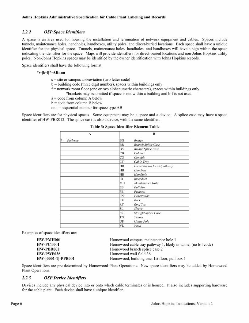
2.2.2 OSP Space Identifiers A space is an area used for housing the installation and termination of network equipment and cables. Spaces include tunnels, maintenance holes, handholes, handboxes, utility poles, and direct-buried locations. Each space shall have a unique identifier for the physical space. Tunnels, maintenance holes, handholes, and handboxes will have a sign within the space indicating the identifier for the space. Maps will provide identifiers for direct-buried locations and non-Johns Hopkins utility poles. Non-Johns Hopkins spaces may be identified by the owner identification with Johns Hopkins records.
Space identifiers shall have the following format:
*s-[b-f]*-ABnnn
s = site or campus abbreviation (two letter code) b = building code (three digit number), spaces within buildings only f = network room floor (one or two alphanumeric characters), spaces within buildings only
*brackets may be omitted if space is not within a building and b-f is not used a = code from column A below b = code from column B below nnn = sequential number for space type AB
Space identifiers are for physical spaces. Some equipment may be a space and a device. A splice case may have a space identifier of HW-PBR012. The splice case is also a device, with the same identifier.
Table 3: Space Identifier Element Table
A B
P Pathway BG Bridge BR Branch Splice Case BS Bridge Splice Case CB Cabinet CO Conduit CT Cable Tray DB Direct Buried locale/pathway HB Handbox HH Handhole ID Innerduct MH Maintenance Hole PB Pull Box PE Pedestal PN Penetration RK Rack RT Roof Top SL Sleeve SS Straight Splice Case TN Tunnel UP Utility Pole VL Vault
Examples of space identifiers are:
HW-PMH001 Homewood campus, maintenance hole 1 HW-PCT001 Homewood cable tray pathway 1, likely in tunnel (no b-f code) HW-PBR002 Homewood branch splice case 2 HW-PWF036 Homewood wall field 36 HW-[0001-1]-PPB001 Homewood, building one, 1st floor, pull box 1
Space identifiers are pre-determined by Homewood Plant Operations. New space identifiers may be added by Homewood Plant Operations.
2.2.3 OSP Device Identifiers Devices include any physical device into or onto which cable terminates or is housed. It also includes supporting hardware for the cable plant. Each device shall have a unique identifier.

Johns Hopkins Administrative Specification for Cable Plant Labeling and Records
Johns Hopkins Institutions, Version 2 Page 7
Device identifiers shall have the following format:
*s-[b-f]*-ABnnn
s = site or campus abbreviation (two letter code) b = building code (three digit number), spaces within buildings only f = network room floor (one or two alphanumeric characters), spaces within buildings only *brackets may be omitted if device is not within a building a = code from column A below b = code from column B below nnn = sequential number for space type AB
Table 4: Device Identifier Element Table
A B C Copper BK Block CA Case CC Cross Connect ET Entrance Terminal FP Feed Pair HP House Pair MS Mechanical Splice PL Panel PT Port SH Sheath ST Stub TM Termination F Fiber CA Case FS Fusion Splice MS Mechanical Splice PL Panel PT Port SH Sheath TM Termination X Coax TP Tap (coax) TM Termination
CMR Camera DLR Dialer ETL Emergency Telephone FAX Fax GBR Glass Break HNS Handset KSK Kiosk MDM Modem MIC Microphone MNT Monitor PAY Payphone PC PC PB Pull box RDR Reader SNS Sensor SPK Speaker STR Strike TEL Telephone TV Television
A Active Devices
WLP Wall Phone
Devices may have an additional element to indicate a division within the device. The format for division it to add “.ddd” to the device identifier, where “.ddd” is a sequential number.
Examples of device identifiers are:
HW-CMS001 Homewood copper mechanical splice 1 HW-CMS001.004 Homewood copper mechanical splice 1, splice module 4 HW-ADLR001 Homewood dialer 1 (e.g. emergency phone)

Johns Hopkins Administrative Specification for Cable Plant Labeling and Records
Page 8 Johns Hopkins Institutions, Version 2
HW-[0004-G]-APAY001 Homewood, building 4, ground floor, payphone 1
Device identifiers are pre-determined by Homewood Plant Operations. New device identifiers may be added by Homewood Plant Operations only. Vendors shall contact Plant Operations for device identifiers.
2.2.4 OSP Pathway Identifiers Pathways shall be identified by the space of origin, the space of destination, and the specific pathway element. Pathways include conduits, direct-buried pathways, and aerial pathways.
Pathway identifiers shall have the following format:
s-[sp1]/[sp2]-pe(sz).sd
[s1-sp1]/[s2-sp2]-pe(sz).sd (inter-campus pathways)
s1 = site or campus abbreviation (two letter code) s2 = site or campus abbreviation (two letter code) sp1 = space identifier of origin or destination sp2 = space identifier of origin or destination *brackets may be omitted if pathway is not to, from, or within a building pe = pathway element sz = size of pathway element, when applicable (e.g. 4”) sd = element subdivision, when applicable (e.g. innerduct)
Pathway elements are identified as:
Space identifier for the element plus a sequential number, plus a pathway size, where applicable. These identifiers are specific for a given pathway. For example, PDB001 can be used to describe a direct-buried pathway between two points. The same identifier can be used between two other point since the initial parts of the pathway identifier shall be different (e.g. HW-[004-1A]/PDB002-PDB001 and HW-[006-GA]/PDB003-PDB001).
Example of pathway identifiers are:
HW-PMH004/PTN001-PCN001(4”)
(path from Homewood maintenance hole 4 to tunnel 1 using the 1st conduit, which is a 4” conduit, between these 2 points)
HW-[004-1A]/PDB002-PDB001
(path from Homewood Bldg 4, 1st floor, network room A to direct-buried location 2 using direct-buried path 1 between these 2 points)
HW-PBR003/PMH003-CST001
(path from Homewood branch splice 3 to maintenance hole 3 to copper stub 1- this is a stub out of the splice case in the maintenance hole)
HW-PTN001/PTN001-PCT001(9”)
(path from Homewood tunnel 1 to tunnel 1 using cable tray 1 which is 9” wide- path within a single tunnel segment)
HW-PMH003/PMH004-PCN002(4”).PID1
(path from Homewood maintenance hole 3 to maintenance hole 4 using innerduct 1 of the 2nd conduit which is a 4” conduit).
Vendors should confirm pathway identifiers with Plant Operations during planning and design of an installation.
2.2.5 Interbuilding Backbone Cabling Identifier Physical Labeling

Johns Hopkins Administrative Specification for Cable Plant Labeling and Records
Johns Hopkins Institutions, Version 2 Page 9
Backbone cabling shall be identified by the building and network room of origin and destination and a sequentially numbered identifier, to accommodate multiple cables running between these two network rooms. Backbone cablings shall be identified by a logical identifier indicating the specific pairs/strands from the source of service (section 4.3.2.).
The physical identifier shall have the following format:
If the cable originates and ends on the same campus and
1. runs between two buildings’ network rooms: s-[b1-ft1]/[b2-ft2]-nnn 2. runs between a building and a splice: s-[b1-ft1]/dv-nnn 3. runs between two splices: s-dv1/dv2-nnn
If the cable originates and ends on different campuses and
1. runs between two buildings’ network rooms: [s-b1-ft1]/[s-b2-ft2]-nnn 2. runs between a building and a splice: [s-b1-ft1]/[s-dv]-nnn 3. runs between two splices: [s-dv1]/[s-dv2]-nnn
s = site or campus abbreviation b = building code f = network room floor t = network room identifier dv = OSP device or space nnn = sequential cable number
Examples of physical identifiers:
HW-[0001-GA]/[0002-1A]-002 Cable from building to building
(Cable from Homewood building 1, ground floor, network room A to building 2, 1st floor, network room A, 2nd physical cable between these 2 points)
HW-[0001-GA]/PBR001-001 Cable from building to splice
(Cable from Homewood building 1, ground floor, network room A to branch splice 1, 1st cable between these 2 points.)
HW-PBR001/PSS001-001 Cable from splice to splice
(Cable from Homewood branch splice 1 to straight splice 1- first cable between these 2 points)
[EC-PSS002]/[HW-PSS001]-001 Cable from splice on one campus to splice one second campus
(Cable from Eastern straight splice 2 to Homewood straight splice 1, 1st cable between these 2 points)
HW-[0001-GA]/ARDR005-001 Cable from building to parking lot card reader
(Cable from Homewood building 1, ground floor, network room A to active device reader 5, 1st physical cable between these 2 points)
The label elements on either side of the slash are positioned in alphabetical order. This rule applies to all labels within this standard when two label elements are separated by a slash.
Only Plant Operations shall approve deviations from these cable identifiers.
Logical Labeling
Backbone cables shall be identified by the originating cable identifier, including pair/strand count. This label does not have to be unique to a physical cable. For example, a single logical label may follow several physical segments of a cable run connected by straight splices. This label will track the path of each pair/strand from the origin of service to the ultimate point of service.
The logical identifier shall have the following format:
s-[b-tf]-nnn.d1-d2
s = site or campus abbreviation

Johns Hopkins Administrative Specification for Cable Plant Labeling and Records
Page 10 Johns Hopkins Institutions, Version 2
b = building code for source of service f = network room floor t = network room identifier nnn = sequential cable number for cable leaving source building d1 = initial or only pair/strand number d2 = last pair/strand number (if applicable)
Examples of logical identifiers:
HW-[0006-1A]-001.301-400
(Logical pairs 301-400 of the 1st cable leaving Homewood building 6, 1st floor, network room A)
HW-[0001-GA]-002.1-36
(Logical strands 1-36 of the 2nd cable leaving Homewood building 1, ground floor, network room A)
When labeling hybrid optical fiber, strand 1 is multimode fiber with additional multimode fibers sequentially numbers. The first single mode fiber takes the next sequential number and does not restart the numbering sequence at 1.
Plant Operations may waive logical labeling as a requirement for new installations.
2.2.6 Network Room Identifiers Each network rooms shall have a unique identifier with a format described in this section. Each network room will have a small sign on the door indicating the identifier for the room. This sign may be on the inside of the door, if Plant Operations is prohibited from placing it on the outside of the door.
Network rooms identifiers shall have the following format:
s-b-ft HW-0001-GA, HW-0002-1A, EC-001-1A
s = site or campus abbreviation (two letter code) b = building code (three digit number) f = network room floor (one or two alphanumeric characters) t = network room identifier (single sequential letter)
Floor identifiers can be numbers, letters, or a number/letter combination and can be two digits, if needed. This will accommodate 99 floors and includes ground [g], basement [b], mezzanine [m], penthouse [p], lobby [l], and sub-basement [s] (second sub-basement [s2], etc.). Additional floor identifiers may be added by Homewood Plant Operations only.
Network room identifiers are sequential letters starting at [A]. Network rooms include any space housing network equipment, device, and means of cable termination including splice cases and wall fields. Additional network room identifiers may be added by Homewood Plant Operations only. Vendors shall contact Plant Operations for network room identifiers.
2.2.7 Intrabuilding Backbone Cabling Identifier Physical Labeling
Intra-building backbone cabling may be identified by the building and network room of origin and destination and a sequentially numbered identifier, to accommodate multiple cables running between these two network rooms. Intra-building backbone cablings may be identified by a logical identifier indicating the specific pairs/strands from the source of service (section 4.6.1.2.).
The physical identifier may have the following format:
s-b-f1t1/ f2t2-nnn
s = site or campus abbreviation b = building code f = network room floor t = network room identifier nnn = sequential cable number
Examples of physical identifiers:

Johns Hopkins Administrative Specification for Cable Plant Labeling and Records
Johns Hopkins Institutions, Version 2 Page 11
HW-0001-GA/1A-002 (Cable from Homewood building 1, ground floor, network room A to 1st floor, network room A, 2nd physical cable between these 2 points)
Logical labeling
Intra-building backbone cables may be identified by the originating cable identifier, including pair/strand count. This label does not have to be unique to a physical cable. For example, a single logical label may follow several physical segments of a cable run connected by straight splices. This label will track the path of each pair/strand from the origin of service to the ultimate point of service. Not all intra-building backbone cables may have a logical label. For example, optical fiber connecting two switches does not have a logical identifier. Only optical fiber directly cross-connected to optical fiber within an inter-building backbone cable would have a logical label.
The logical identifier may have the following format:
s-[b-tf]-nnn.d1-d2
s = site or campus abbreviation b = building code for source of service f = network room floor t = network room identifier nnn = sequential cable number for cable leaving source building d1 = initial or only pair/strand number d2 = last pair/strand number (if applicable)
Examples of logical identifiers:
HW-[0006-1A]-001.301-400 (Logical pairs 301-400 of the 1st cable leaving Homewood building 6, 1st floor, network room A)
HW-[0001-GA]-002.1-36 (Logical strands 1-36 of the 2nd cable leaving Homewood building 1, ground floor, network room A)
When labeling hybrid optical fiber, strand 1 is multimode fiber with additional multimode fibers sequentially numbers. The first single mode fiber takes the next sequential number and does not restart the numbering sequence at 1.
Networking or Telecommunications may waive logical labeling as a requirement for new installations.
2.2.8 ISP Pathway Identifiers Pathways shall be identified by the space of origin, the space of destination, and the specific pathway element.
Pathway identifiers shall have the following format:
s-b-f1t1/ f2t2-pe(sz).sd
s = site or campus abbreviation b = building code f = network room floor t = network room identifier pe = pathway element sz = size of pathway element, when applicable (e.g. 4”) sd = element subdivision, when applicable (e.g. innerduct)
Pathway elements are identified as:
Space identifier for the element plus a sequential number, plus a pathway size, where applicable.
Example of pathway identifiers are:
HW-0001-1A/2A-PCN001(4”)
(path from building 1, network room 1A to network room 2A. It is conduit #1 between these spaces and is 4”)
HW-0001-2A/2B-PCT001(9”)

Johns Hopkins Administrative Specification for Cable Plant Labeling and Records
Page 12 Johns Hopkins Institutions, Version 2
(path from building 1, network room 2A to network room 2B. It is cable tray #1 between these spaces and is 9”wide)
HW-0001-1A/2A-PCN001(4”).PID1
(path from building 1, network room 1A to network room 2A. It is conduit #1, innerduct 1 between these spaces and is 4”)
2.2.9 Horizontal Cable Identifiers Physical Labeling
Horizontal links may be identified by the network room of origin and a sequentially numbered identifier based on termination location. Horizontal links may be identified by a logical identifier indicating the specific pairs/strands from the source of service (section 5.9.2.1.2).
The physical identifier may have the following format:
ft-annn
f = network room floor t = network room identifier a = one or two letters uniquely identifying the single patch panel, group of patch panels, termination block, or group of termination blocks nnn = number uniquely identifying the port or block section within the single patch panel, group of patch panels, termination block, or group of termination blocks where the cable terminates
Examples of physical identifiers:
GA-B002 (Cable from ground floor, network room A, termination device B, location 2)
Termination devices shall be number continuously in a vertical stack of the same type of termination device. Patch panels on the same rack shall be identified with the same single letters (rack A, B, C…). A set of two 48-port panels would be labeled as A001 through A096. Termination blocks shall also be identified as groups with sequential numbering within a group. A set of two 300-pair 110 blocks would be labeled B001 through B144. Sequential lettering is to include all forms of cabling termination and be mutually exclusive between patch panels, termination blocks, and any other form of cable termination.
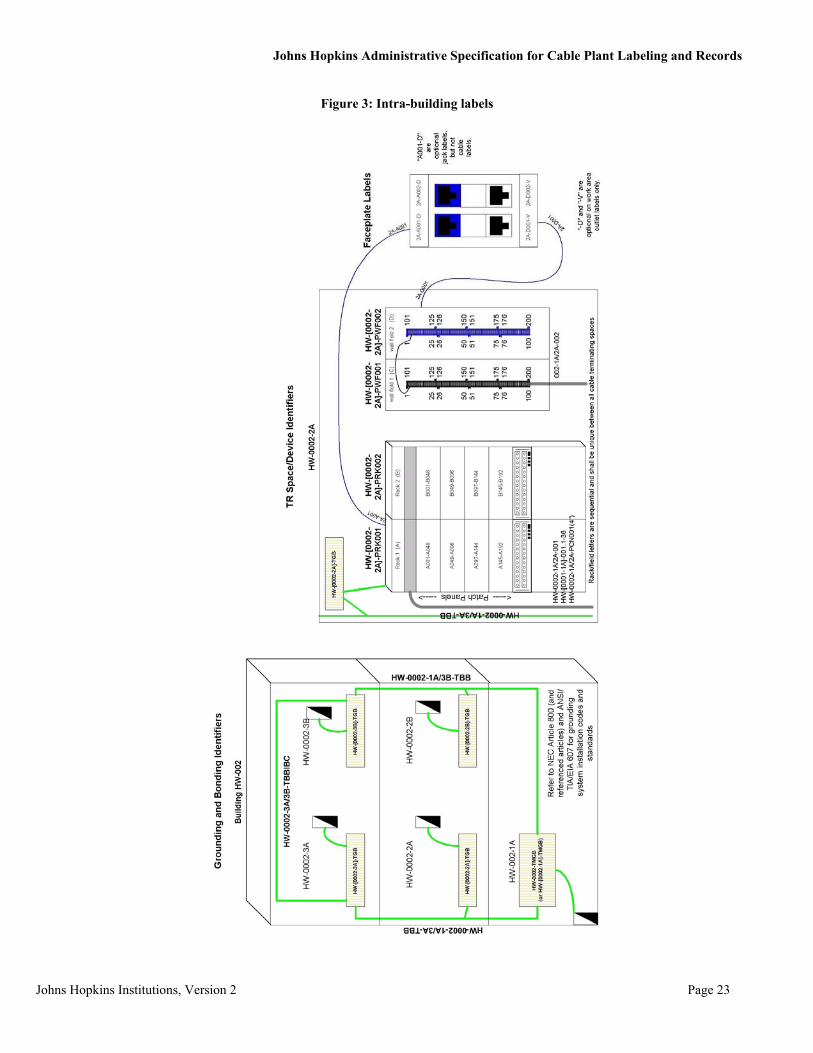
The horizontal link identifier shall be the work area outlet identifier. A “-V” for voice or a “-D” for data may be added to the end of the work area outlet identifier, but not to the horizontal link identifier. The “ft-” portion of the horizontal link identifier may be omitted from the work area outlet identifier, if a building has a single network room. This portion should not be omitted from the horizontal link identifier, just the work area outlet identifier (on the faceplate).
Examples of optional work area outlet identifiers:
A002 (Optional format for work area outlet wired from the only building network room, termination device A, location 2)
B002-V (Optional format for work area outlet wired from the only building network room, telecommunication termination device B, location 2)
A002-D (Optional format for work area outlet wired from the only building network room, patch panel A, port 2)
Logical labeling
Horizontal link may be identified by the originating cable identifier, including pair/strand count. This label does not have to be unique to a physical cable. For example, a single logical label may follow several physical segments of a cable run connected by straight splices. This label will track the path of each pair/strand from the origin of service to the ultimate point of service.
The logical identifier may have the following format:
b-tf-nnn.d1-d2
b = building code for source of service f = network room floor t = network room identifier

Johns Hopkins Administrative Specification for Cable Plant Labeling and Records
Johns Hopkins Institutions, Version 2 Page 13
nnn = sequential cable number for cable leaving source building d1 = initial or only pair/strand number d2 = last pair/strand number (if applicable)
Examples of logical identifiers:
0006-1A-001.301 (Logical pairs 301 of the 1st cable leaving Homewood building 6, 1st floor, network room A)
0001-GA-002.1-2 (Logical strands 1-2 of the 2nd cable leaving Homewood building 1, ground floor, network room A)
When labeling hybrid optical fiber, strand 1 is multimode fiber with additional multimode fibers sequentially numbers. The first single mode fiber takes the next sequential number and does not restart the numbering sequence at 1.
Networking or Telecommunications may waive logical labeling as a requirement for new installations.
2.2.10 Firestopping Identifier A firestopping location identifier shall identify each installation of Firestopping material.
The firestopping location identifier shall have the following format:
s-[b-f]-FSLn(h) HW-[0001-1]-FSL01(2)
s = site or campus abbreviation b = building code for source of service f = building floor (one or two alphanumeric characters) n = two to four numeric characters identifying one firestopping location h = one numeric character specifying the hour rating of the firestopping system
Each firestopping location shall be labeled on both sides, where possible, of the penetration with the firestopping identifier. Each firestopping location shall be identified with a firestopping warning label similar to this label. The label shall include the manufacturer of the product, the installer and company name, the UL number for the product, the rating of the material, the installation date, and the number and type of cables passing through the opening.
Figure 1: Sample Firestopping Label
The firestopping warning label can include the firestopping location identifier, eliminating the need for a separate label. The firestopping label shall be located within 12 inches of the penetration and, when possible, on both sides of the penetration.

Johns Hopkins Administrative Specification for Cable Plant Labeling and Records
Page 14 Johns Hopkins Institutions, Version 2
Penetration modifications requiring the repair/re-installation of the firestopping material require the addition of a new firestopping warning label. No previous firestopping warning labels shall be removed or obscured by new labels. In the event the penetration is completely cleaned of existing firestopping material and new material installed, the previous label shall be removed or obscured completely.
2.2.11 Grounding and Bonding Identifiers 2.2.11.1 TMGB Identifier
The Telecommunications Main Grounding Busbar is the main busbar for a building. The TMBG identifier is used to identify the single TMGB present in a single building system. The TMGB shall be labeled with the TMGB identifier.
TMBG identifier shall have the following format:
s-bf*t*-TMGB HW-0001-TMGB HW-[0001-1A]-TMGB
s = site or campus abbreviation b = building code (three digit number) f = optional network room floor (one or two alphanumeric characters)* t = optional network room identifier (single sequential letter)*
* As each building shall only have one TMGB, no network room identifier is required. It may be added as on option to act as a reminder to its location in a building with multiple network rooms. Entrance facilities with a TMGB shall be labeled as a network rooms.
2.2.11.2 TGB Identifier
The Telecommunication Grounding Busbar is a point of contact for telecommunication and network equipment to the building ground by way of the TMGB. Each network room should have a TGB, if it is not a building’s main cross-connect (campus intermediary cross-connect for a specific building) with a TMGB. The TGB shall be labeled with the TGB identifier.
The TGB identifier shall have the following format:
s-[b-ft]-TGB HW-[0002-1A]-TGB
s = site or campus abbreviation b = building code (three digit number) f = network room floor (one or two alphanumeric characters) t = network room identifier (single sequential letter)
2.2.11.3 TBB Identifier
The Telecommunication Bonding Backbone is a conductor that interconnects the TMGB to one or more telecommunication bonding backbones within a building system. A building system may have multiple telecommunication bonding backbones. The TBB shall be labeled with a TBB identifier.
Contiguous buildings may share network grounding, if the buildings share a common electrical ground. Otherwise, each section of an overall building shell shall have its own network grounding system matching the building electrical power grounding system topology.
The TBB identifier shall have the following format:
s-b1-ft1/ft2-TBB HW-0001-1A/2A-TBB
s-[b1-ft1]/[b2-ft2]-TBB HW-[0001-1A]/[0002-2A]-TBB Two attached buildings with a common electrical ground
s = site or campus abbreviation b = building code (three digit number) f = network room floor (one or two alphanumeric characters) t = network room identifier (single sequential letter)

Johns Hopkins Administrative Specification for Cable Plant Labeling and Records
Johns Hopkins Institutions, Version 2 Page 15
2.2.11.4 GE Identifier
The Grounding Equalizer is a conductor that interconnects two telecommunication bonding backbones within a building system. A building system may have multiple GEs. The GE shall be labeled with a GE identifier.
Contiguous buildings may share network grounding, if the buildings share a common electrical ground. Otherwise, each section of an overall building shell shall have its own network grounding system.
The GE identifier shall have the following format:
s-b1-ft1/ft2-GE HW-0001-1A/1B-GE
s-[b1-ft1]/[b2-ft2]-GE HW-[0001-3A]/[0002-3B]-GE Two buildings with a common electrical ground
s = site or campus abbreviation b = building code (three digit number) f = network room floor (one or two alphanumeric characters) t = network room identifier (single sequential letter)
2.3 Records Plant Operations shall maintain all cable plant records for OSP elements. Any changes to the cable plant shall be reported to Plant Operations for record entry/modification.
Required Linkages
Each identifier shall be linked to each record or report in which it appears.
Required Reports
Homewood Plant Operations shall make available to IT@JH or other JH entities, at Plant Operations discretion, reports comprising information from groups of records. Each report shall list all records of the selected identifier and all information in those records, or any desired subset of the records and of the information in those records.
2.3.1 Campus/Building Records The site or campus records shall contain the following information:
• site or campus name • site or campus location (e.g.: street address) • contact information for local administrator(s) of infrastructure • list of all buildings at the site or campus • location of main cross-connect, if applicable • access hours, if applicable • comments
The building records shall contain the following information:
• building name • building location (e.g.: street address) • a list of all network rooms and their locations in the building • contact information for access • access hours • comments

Johns Hopkins Administrative Specification for Cable Plant Labeling and Records
Page 16 Johns Hopkins Institutions, Version 2
2.3.2 Space Records Space records shall contain the following information based on space type:
Table 5: Space Record Requirements
X- Required
O- Optional
Brid
ge
Cab
inet
C
able
Tra
y D
irect
-bur
ied
Loca
tions
H
andb
oxes
H
andh
oles
M
aint
enan
ce H
oles
N
etw
ork
Roo
ms
Splic
e C
ases
U
tility
Pol
es
Pede
stal
Pene
tratio
n R
ack
Roo
f top
Slee
ve
Tunn
el
Vau
lt W
all F
ield
Building identifier X X X X X
Comments X X X X X X X X X X X X X X X
Contact information for local administrator(s) X X X X X X X X X X X X X X X
Dead conductors
Environmental information O O X X X X X O O O O O X X
Grounding (Y/N) X X X X X X X X
Hours of access X X X X X X X X X X X X X X X
Key information X X X X X
Location description X X X X X X X X X X X X X X X
Logical cable identifiers in space X X X X X X X X X X X X X X X
Maintenance records (date and service) X X X X X X X X X X X X X X X
Manufacturer X X X X X X X X
Model X X X X X X
Non-network/telecom cabling/ systems/equipment present (Y/N) X X X X X X X X X X X X
Physical cable identifiers in space X X X X X X X X X X X X X X X
Site or campus identifier X X X X X X X X X X X X X X X
Size X X X X X X X X X X X X
Space Identifier X X X X X X X X X X X X X X X
Stub present (Y/N) X X
Type of Space X X X X X X X X X X X X X X X
Firestop identifier
See
Dev
ice
Rec
ords
X
See
Dev
ice
Rec
ords
X
See
Dev
ice
Rec
ords

Johns Hopkins Administrative Specification for Cable Plant Labeling and Records
Johns Hopkins Institutions, Version 2 Page 17
2.3.3 Device Records
Device records shall contain the following information based on device type:
Table 6: Device Records Requirements
Copper Fiber
CO
AX
Active Devices
X- Required O- Optional
Blo
ck
Cas
e C
ross
Con
nect
M
echa
nica
l Spl
ice
Pane
l Po
rt Sh
eath
C
ase
Fusi
on S
plic
e M
echa
nica
l Spl
ice
Pane
l Po
rt Sh
eath
Te
rmin
atio
n Ta
p Te
rmin
atio
n C
amer
a D
iale
r Fa
x G
lass
Bre
ak
Han
dset
M
odem
M
icro
phon
e M
onito
r Pa
ypho
ne
PC
Pull
box
Rea
der
Sens
or
Spea
ker
Strik
e Te
leph
one
Tele
visi
on
Wal
l pho
ne
Building identifier X X X X X X X X X X X X X X X X X X X X X X X X X X X X X X X X X X
Classification (branch, bridge, straight) X X X
Comments X X X X X X X X X X X X X X X X X X X X X X X X X X X X X X X X X X
Conductors in X X X
Conductors out X X X
Contact information for local administrator(s) X X X X X X X X X X X X X X X X X X X X X X X X X X X X X X X X X X
Dead conductors X X X
Device Identifier X X X X X X X X X X X X X X X X X X X X X X X X X X X X X X X X X X
Environmental information X X X X X X X X X X X X X X X X X X X X X X X X X X X X X X X X X X
Firestop identifier X X
Grounding (Y/N) X X X X X X X X X X X X O X O O O O O O O O O X O O O O O O
Hours of access X X X X X X X X X X X X X X X X X X X X X X X X X X X X X X X X X X
Location description X X X X X X X X X X X X X X X X X X X X X X X X X X X X X X X X X X
Logical cable identifiers to device X X X X X X X X X X X X X X X X X X X X X X X X X X X X X X X X X X
Maintenance records (date and service) X X X X X X X X X X X X X X X X X X X X X X X X X X X X X X X X X X
Manufacturer X X X X X X X X X X X X O X X X X X X O X X X O X O O O
Model X X X X X X X X X X X X O X X X X X X O X X X O X O O O
Physical cable identifiers to device X X X X X X X X X X X X X X X X X X X X X X X X X X X X X X X X X X
Site or campus identifier X X X X X X X X X X X X X X X X X X X X X X X X X X X X X X X X X X
Size X X X X X X
Stub present (Y/N) X X X
Telephone number X O O X X
Type of Device X X X X X X X X X X X X X X X X X X X X X X X X X X X X X X X X X X
2.3.4 Pathway Records The pathway records shall contain the following information:
• pathway identifier (the primary indexing identifier, e.g.: HW-PMH004/PTN001-PCN001(4”)) • physical cable identifier(s) in pathway • type of pathway (e.g.: 4” PVC conduit, 3 x 1.5” innerduct) • fill ratio
Johns Hopkins Administrative Specification for Cable Plant Labeling and Records
Page 18 Johns Hopkins Institutions, Version 2
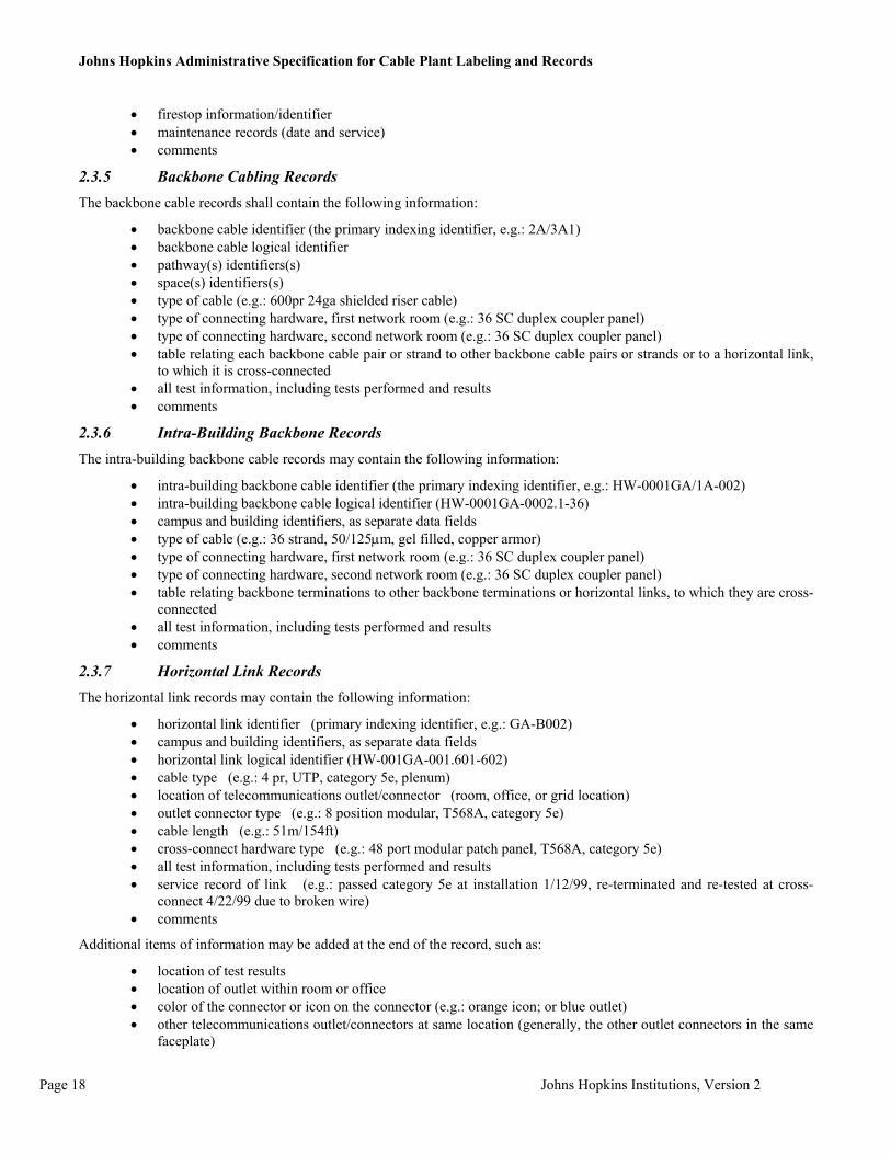
• firestop information/identifier • maintenance records (date and service) • comments
2.3.5 Backbone Cabling Records The backbone cable records shall contain the following information:
• backbone cable identifier (the primary indexing identifier, e.g.: 2A/3A1) • backbone cable logical identifier • pathway(s) identifiers(s) • space(s) identifiers(s) • type of cable (e.g.: 600pr 24ga shielded riser cable) • type of connecting hardware, first network room (e.g.: 36 SC duplex coupler panel) • type of connecting hardware, second network room (e.g.: 36 SC duplex coupler panel) • table relating each backbone cable pair or strand to other backbone cable pairs or strands or to a horizontal link,
to which it is cross-connected • all test information, including tests performed and results • comments
2.3.6 Intra-Building Backbone Records The intra-building backbone cable records may contain the following information:
• intra-building backbone cable identifier (the primary indexing identifier, e.g.: HW-0001GA/1A-002) • intra-building backbone cable logical identifier (HW-0001GA-0002.1-36) • campus and building identifiers, as separate data fields • type of cable (e.g.: 36 strand, 50/125µm, gel filled, copper armor) • type of connecting hardware, first network room (e.g.: 36 SC duplex coupler panel) • type of connecting hardware, second network room (e.g.: 36 SC duplex coupler panel) • table relating backbone terminations to other backbone terminations or horizontal links, to which they are cross-
connected • all test information, including tests performed and results • comments
2.3.7 Horizontal Link Records The horizontal link records may contain the following information:
• horizontal link identifier (primary indexing identifier, e.g.: GA-B002) • campus and building identifiers, as separate data fields • horizontal link logical identifier (HW-001GA-001.601-602) • cable type (e.g.: 4 pr, UTP, category 5e, plenum) • location of telecommunications outlet/connector (room, office, or grid location) • outlet connector type (e.g.: 8 position modular, T568A, category 5e) • cable length (e.g.: 51m/154ft) • cross-connect hardware type (e.g.: 48 port modular patch panel, T568A, category 5e) • all test information, including tests performed and results • service record of link (e.g.: passed category 5e at installation 1/12/99, re-terminated and re-tested at cross-
connect 4/22/99 due to broken wire) • comments
Additional items of information may be added at the end of the record, such as: • location of test results • location of outlet within room or office • color of the connector or icon on the connector (e.g.: orange icon; or blue outlet) • other telecommunications outlet/connectors at same location (generally, the other outlet connectors in the same
faceplate)

Johns Hopkins Administrative Specification for Cable Plant Labeling and Records
Johns Hopkins Institutions, Version 2 Page 19
• faceplate configuration (e.g.: single gang, four port, telco ivory) • position of outlet connector on faceplate or MUTOA (eg.: top left) • pathway to outlet (e.g.: fishable wall or surface raceway) • presence or absence of MUTOA (is there a MUTOA in this link, yes or no) • length of work area cord if MUTOA is present • presence of absence of CP (is there a CP in this link, yes or no) • equipment circuit currently using link (e.g.: 100BaseT switch port #16) • current user name (e.g.: Max Headroom)
2.3.8 Firestopping Records The firestopping records shall contain the following information:
• firestopping location identifier (primary indexing identifier, e.g.: 3-FSL02(3)) • location of the firestopping installation (eg.: room number and location within room) • type and manufacturer of firestopping installed • UL number for firestopping material • date of firestopping installation • name of installer of firestopping material • number and cable-type description of cables in pathway • service record of firestopping location (e.g.: 4/22/99 firestopping removed and replaced with same type by ABC
Cabling to add cabling runs) • comments
2.3.9 Grounding and Bonding Records 2.3.9.1 TMBG Records The TMBG record shall contain the following information:
• telecommunications main grounding busbar identifier (primary indexing identifier, e.g.: HW-001-TMBG) • location of the TMGB (network room identifier) • size of the TMGB • location of attachment of TMGB to electrical system ground or building structural steel • location of test results for any tests performed on the TMGB, such as resistance to ground • comments
2.3.9.2 TGB Records The TGB records shall contain the following information:
• telecommunications grounding busbar identifier (primary indexing identifier, e.g.: HW-0032A-TGB) • location of TGB (network room identifier) • size of the TGB • TBB identifier • GE identifier, if present • Comments
2.4 Color Coding Identification This section is taken with minimal adjustment from the ANSI/TIA/EIA-606-A, draft1j.
This section describes requirements for color coding in administration of a cabling system.
Areas of cabling system infrastructure addressed are termination fields and horizontal cabling.
2.4.1 Color Coding of Termination Fields Color coding of termination fields can make administration more efficient by making the cabling system more intuitive and easily understood for those maintaining the system.

Johns Hopkins Administrative Specification for Cable Plant Labeling and Records
Page 20 Johns Hopkins Institutions, Version 2
The color coding of termination fields specified in this Standard is based on the topology of backbone and horizontal cabling specified in ANSI/TIA/EIA-568-B.1 which allows one level of cross-connection in horizontal cabling and two levels of cross-connection in backbone cabling.
Cross-connections generally connect termination fields of different colors.
a. A demarcation point, for example, a central office termination, shall be identified by the color orange (Pantone 150C).
b. Network connections on the system-owner side of a demarcation point shall be identified by the color green (Pantone 353C).
c. Connections from common equipment, for example, PBXs, computers, LANs, or multiplexers, shall be identified by the color purple (Pantone 264C).
d. Connections to key telephone systems shall be identified by the color red (Pantone 184C). e. Terminations at both ends of intra-building backbone cables originating in the main cross-connect shall be
identified by the color white. f. Terminations at both ends of intra-building backbone cables not originating in the main cross-connect shall be
identified by the color gray (Pantone 422C). g. Terminations at both ends of inter-building backbone cables shall be identified by the color brown (Pantone
465C). h. Terminations of horizontal cable in the network room shall be identified by the color blue (Pantone 291C). i. Terminations of other circuits, including, but not limited to, alarms, security, or energy management, shall be
identified by the color yellow (Pantone 101C).
A summary and illustration of these requirements are shown below.
Table 7: Summary of Termination Color Coding
Termination Type Color Pantone # Typical Application
demarcation point orange 150C central office connection
network connection green 353C user side of central office connection
common equipment purple 264C connections to PBX, mainframe computer, LAN, multiplexer
key system red 184C connections to key telephone systems
first level backbone white terminations of intra-building backbone cable connecting MC to ICs
second level backbone gray 422C termination of intra-building backbone cable connecting ICs to network rooms
Inter-building backbone brown 465C termination of backbone cable between buildings
horizontal blue 291C terminations of horizontal cable in network rooms
Other yellow 101C alarms, security, or energy management
Refer to the ANSI/TIA/EIA-606-A standard, figure 2, for an illustration of this.
2.4.2. Color coding in horizontal cabling 2.4.2.1 Horizontal Cabling Components
Color coding may be used to differentiate horizontal cable runs, to identify services connected by patch cords, or to identify various services available in a work area outlet. To be of most value, such color coding should be consistent throughout the system.
2.4.2.2 Optical Fiber Cabling Components
Optical Fiber Patch Cords
Most communications circuits using optical fiber as a transmission medium require two strands of fiber. Patch cords and station cords with simplex connectors should use different color connectors or strain relief boots to assist in maintaining proper polarity. Refer to ANSI/TIA/EIA-568-B.1 for recommendations on maintaining polarity.

Johns Hopkins Administrative Specification for Cable Plant Labeling and Records
Johns Hopkins Institutions, Version 2 Page 21
Optical Fiber Types and Connector Types
Cabling systems may contain optical fiber with different core sizes, or different bandwidth specifications within the same core size. System operators may find it desirable to identify terminations by color to assist in maintaining compatibility when making connections.
Angled PC, or APC, optical fiber connectors are not compatible with other types, and system operators may find it desirable to identify these terminations by color to assist in maintaining compatible connections.
3 Installation Specifications
Records are maintained by Homewood Plant Operations for OSP elements. Required record information for all spaces, pathways, devices, and cables are included in this document. Required information for grounding and firestopping elements are also included.
Campus drawings and maps are maintained by Homewood Plant Operations.
Identifiers for labels are determined by Homewood Plant Operations. Specifications for these identifiers are included in this specification and include all spaces, pathways, devices, and cables. Identifiers for grounding elements are also included.
The Contractor shall confirm the labeling plan with JHU prior to labeling. Questions about labeling shall be brought to JHU prior to labeling. Incorrect labels shall be corrected at the Contractor’s expense.
Records shall be presented in electronic format. Records may be presented in text-based, tab-delimited format. Records may be presented in Microsoft Excel spreadsheets. The Contractor shall coordinate the format for delivery of records with Johns Hopkins.
The Contractor shall provide as-built drawings upon completion. The Contractor shall format these drawings as AutoCAD files compatible with AutoCAD 2000 (DWG or DXF file).

Johns Hopkins Administrative Specification for Cable Plant Labeling and Records
Page 22 Johns Hopkins Institutions, Version 2
Figure 2: Sample Map
Johns Hopkins Administrative Specification for Cable Plant Labeling and Records
Johns Hopkins Institutions, Version 2 Page 23
Figure 3: Intra-building labels
Johns Hopkins Administrative Specification for Cable Plant Labeling and Records
Page 24 Johns Hopkins Institutions, Version 2
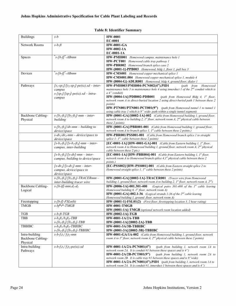
Table 8: Identifier Summary
Buildings s-b HW-0001 EC-0001
Network Rooms s-b-ft HW-0001-GA HW-0002-1A EC-0001-1A
Spaces *s-[b-f]*-ABnnn HW-PMH001 Homewood campus, maintenance hole 1 HW-PCT001 Homewood cable tray pathway 1 HW-PBR002 Homewood branch splice case 2 HW-[0001-1]-PPB003 Homewood, bldg 1, floor 1, pull box 3
Devices *s-[b-f]*-ABnnn HW-CMS001 Homewood copper mechanical splice 1 HW-CMS001.004 Homewood copper mechanical splice 1, module 4 HW-[0004-G]-ADLR001 Homewood, bldg 4, ground floor, dialer 1
Pathways [s1-sp1]/[s2-sp2]-pe(sz).sd – inter-campus s-[sp1]/[sp2]-pe(sz).sd – intra-campus
HW-PMH003/PMH004-PCN002(4”).PID1 (path from Homewood maintenance hole 3 to maintenance hole 4 using innerduct 1 of the 2nd conduit which is a 4” conduit) HW-[0004-1A]/PDB002-PDB001 (path from Homewood Bldg 4, 1st floor, network room A to direct-buried location 2 using direct-buried path 1 between these 2 points) HW-PTN001/PTN001-PCT001(9”) (path from Homewood tunnel 1 to tunnel 1 using cable tray 1 which is 9” wide- path within a single tunnel segment)
Backbone Cabling- Physical
s-[b1-ft1]/[b2-ft2]-nnn – inter-building
HW-[0001-GA]/[0002-1A]-002 (Cable from Homewood building 1, ground floor, network room A to building 2, 1st floor, network room A, 2nd physical cable between these 2 points)
s-[b1-ft1]/dv-nnn – building to device/space
HW-[0001-GA]/PBR001-001 (Cable from Homewood building 1, ground floor, network room A to branch splice 1, 1st cable between these 2 points.)
s-dv1/dv2-nnn – device/space to device/space
HW-PBR001/PSS001-001 (Cable from Homewood branch splice 1 to straight splice 1- 1st cable between these 2 points)
[s-b1-ft1]/[s-b2-ft2]-nnn – inter-campus, inter-building
[EC-0001-1A]/[HW-0001-GA]-001 (Cable from Eastern building 1, 1st floor, network room A to Homewood building 1, ground floor, network room A, 2nd physical cable between these 2 pts.)
[s-b1-ft1]/[s-dv]-nnn – inter-campus, building to device/space
[EC-0001-1A]/[HW-PBR004]-001 (Cable from Eastern building 1, 1st floor, network room A to Homewood branch splice 4,1st physical cable between these 2 points.)
[s-dv1]/[s-dv2]-nnn – inter-campus, device/space to device/space
[EC-PSS002]/[HW-PSS001]-001 (Cable from Eastern straight splice 2 to Homewood straight splice 1, 1st cable between these 2 points)
s-[b1-ft1]/[b2-ft2]-TRACERnnn – inter-building tracer wire
HW-[0001-GA]/[0002-1A]-TRACER001 (Tracer wire from Homewood building 1, ground floor, network room A to building 2, 1st floor, network room A, 2nd)
Backbone Cabling- Logical
s-[b-tf]-nnn.d1-d2 HW-[0006-1A]-001.301-400 (Logical pairs 301-400 of the 1st cable leaving Homewood building 6, 1st floor, network room A) HW-[0001-GA]-002.1-36 (Logical strands 1-36 of the 2nd cable leaving Homewood building 1, ground floor, network room A)
Firestopping s-[b-f]-FSLn(h) HW-[0001-1]-FSL01(2) (First floor, firestopping location 3, 2 hour rating) TMGB s-bf*t*-TMGB HW-0001-TMGB
HW-[0001-1A]-TMGB (optional network room location added) TGB s-b-ft-TGB HW-[0002-1A]-TGB TBB s-b1ft1/b2ft2-TBB
s-[b1-ft1]/[b2-ft2]-TBB HW-0001-1A/2A-TBB HW-[0001-1A]/[0002-2A]-TBB
TBBIBC s-b1ft1/b2ft2-TBBIBC s-[b1-ft1]/[b2-ft2]-TBBIBC
HW-0001-3A/3B-TBBIBC HW-[0001-3A]/[0002-3B]-TBBIBC
Intra-building Backbone Cabling- Physical
s-b-f1t1/ f2t2-nnn HW-0001-GA/1A-002 (Cable from Homewood building 1, ground floor, network room A to 1st floor, network room A, 2nd physical cable between these 2 points)
Intra-building Pathways
s-b-f1t1/ f2t2-pe(sz).sd HW-0001-1A/2A-PCN001(4”) (path from building 1, network room 1A to network room 2A. It is conduit #1 between these spaces and is 4”) HW-0001-2A/2B-PCT001(9”) (path from building 1, network room 2A to network room 2B. It is cable tray #1 between these spaces and is 9”wide) HW-0001-1A/2A-PCN001(4”).PID1 (path from building 1, network room 1A to network room 2A. It is conduit #1, innerduct 1 between these spaces and is 4”)

Johns Hopkins Administrative Specification for Cable Plant Labeling and Records
Johns Hopkins Institutions, Version 2 Page 25
Intra-building Backbone Cabling- Logical
s-[b-tf]-nnn.d1-d2
Same as Backbone Cabling- Logical
Horizontal Links- Physical
ft-annn GA-A002 (cable label) A002 (one network room jack label option) B002-V, A002-D (jack label option)
Horizontal Links- Logical
s-[b-tf]-nnn.d1-d2 Same as Backbone Cabling- Logical