Embed Size (px)
Citation preview
John Zink #33162
1
John Zink Company, LLCJohn Zink Company, LLC
®
Low NOx SolutionsLow NOx Solutionsforfor
Industrial BoilerIndustrial BoilerApplicationsApplications
William William TestaTestaDirector - North American SalesDirector - North American Sales
Table of ContentsTable of Contents
••John Zink Company OverviewJohn Zink Company Overview
••Markets ServedMarkets Served
••TODD Products & TechnologiesTODD Products & Technologies
••Case StudiesCase Studies
John Zink OverviewJohn Zink Overview
John Zink CompanyJohn Zink Company
TODDTODD®®
CombustionCombustion John ZinkJohn Zink®® Gordon-Gordon-PiattPiatt™™ Support &Support &ResourcesResources
Process BurnersProcess Burners
FlaresFlares
Vapor ControlVapor Control
Thermal OxidizersThermal Oxidizers
RefractoryRefractory
Rental EquipmentRental Equipment
OriginationOrigination
R&D Test CenterR&D Test Center
ManufacturingManufacturing
Parts & ServiceParts & Service
Customer EducationCustomer Education
Commercial &Commercial &Industrial BoilerIndustrial BoilerBurnersBurners
Industrial & UtilityIndustrial & UtilityBoiler BurnersBoiler Burners
Duct BurnersDuct Burners
Global OperationsGlobal Operations
John Zink WorldwideJohn Zink Worldwide
WorldWorldHeadquartersHeadquarters
OtherOtherLocationsLocations
Sales offices and independent representatives throughout the worldSales offices and independent representatives throughout the world
CalgaryCalgary
HoustonHoustonTulsaTulsa
BrazilBrazil
UnitedKingdom
UnitedKingdom
LuxembourgLuxembourg
GermanyGermany
FranceFrance
SpainSpain ItalyItalyJapanJapan
SingaporeSingapore
AustraliaAustralia
SheltonShelton
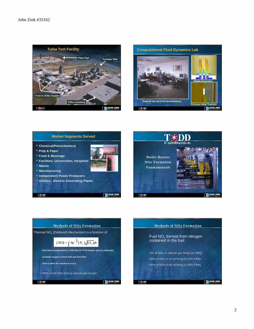
Research and Development FacilityResearch and Development Facility
•• Largest combustion test facility in the worldLargest combustion test facility in the world
•• 14 Full-scale furnaces14 Full-scale furnaces–– 1 Dedicated to Duct Burners1 Dedicated to Duct Burners–– 1 Dedicated to Boiler Burners1 Dedicated to Boiler Burners
•• 2 Lab-scale furnaces2 Lab-scale furnaces
•• Flare testing padFlare testing pad
•• Firing capabilities up toFiring capabilities up to150 MM Btu/hr150 MM Btu/hr
•• Ability to blend and simulate a wide variety of liquid and gasAbility to blend and simulate a wide variety of liquid and gasfuel compositionsfuel compositions
John Zink #33162
2
Fuel & Utility Supply
Flare Pad
Office Building
Furnace Pad
Tulsa Test FacilityTulsa Test Facility Computational Fluid Dynamics LabComputational Fluid Dynamics Lab
Furnace Heat Transfer
Flame Geometry
State of the art CFD workstations
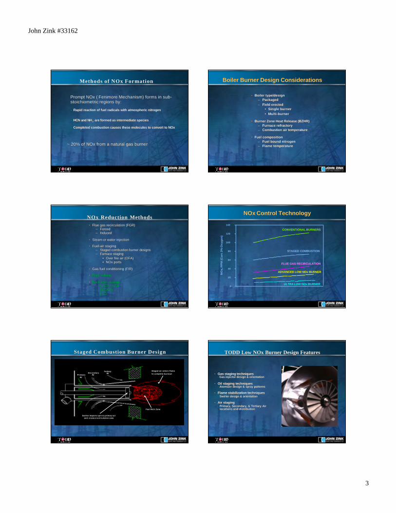
Market Segments ServedMarket Segments Served
•• Chemical/PetrochemicalChemical/Petrochemical
•• Pulp & PaperPulp & Paper
•• Food & BeverageFood & Beverage
•• Facilities, Universities, HospitalsFacilities, Universities, Hospitals
•• MarineMarine
•• ManufacturingManufacturing
•• Independent Power ProducersIndependent Power Producers
•• Utilities - Electric Generating PlantsUtilities - Electric Generating Plants
Boiler BurnerBoiler BurnerNOx FormationNOx Formation
FundamentalsFundamentals
Thermal NOThermal NOxx ( (ZeldovichZeldovich Mechanism) is a function of: Mechanism) is a function of:
– – Peak flame temperatures (> 2500 Peak flame temperatures (> 2500 deg deg F) which breaks apart NF) which breaks apart N2 2 moleculesmolecules
–– Available oxygen to bond with and form NOx Available oxygen to bond with and form NOx
–– Time to allow the reaction to occur Time to allow the reaction to occur
~ 80% of the NOx from a natural gas burner~ 80% of the NOx from a natural gas burner
Methods of NOx FormationMethods of NOx Formation
dtONAeNO Tb
∫−
= ][][][ 22
dtONAeNO Tb−= ][][][
Fuel NOFuel NOxx formed from nitrogen formed from nitrogencontained in the fuelcontained in the fuel
0% of NOx in natural gas firing (no FBN) 0% of NOx in natural gas firing (no FBN)
~ 50% of NOx in #2 oil firing (0.02% FBN)~ 50% of NOx in #2 oil firing (0.02% FBN)
~ 80% of NOx in #6 oil firing (0.30% FBN)~ 80% of NOx in #6 oil firing (0.30% FBN)
Methods of NOx FormationMethods of NOx Formation
John Zink #33162
3
Prompt NOx (Prompt NOx ( FenimoreFenimore Mechanism) forms in sub- Mechanism) forms in sub-stoichiometricstoichiometric regions by: regions by:
–– Rapid reaction of fuel radicals with atmospheric nitrogen Rapid reaction of fuel radicals with atmospheric nitrogen
–– HCN and NH HCN and NH33 are formed as intermediate species are formed as intermediate species
–– Completed combustion causes these molecules to convert to NOx Completed combustion causes these molecules to convert to NOx
~ 20% of NOx from a natural gas burner~ 20% of NOx from a natural gas burner
Methods of NOx FormationMethods of NOx Formation Boiler Burner Design ConsiderationsBoiler Burner Design Considerations
•• Boiler type/designBoiler type/design–– PackagedPackaged–– Field erectedField erected
•• Single burnerSingle burner•• Multi-burnerMulti-burner
•• Burner Zone Heat Release (BZHR)Burner Zone Heat Release (BZHR)–– Furnace refractoryFurnace refractory–– Combustion air temperatureCombustion air temperature
•• Fuel compositionFuel composition–– Fuel bound nitrogenFuel bound nitrogen–– Flame temperatureFlame temperature
•• Flue gas Flue gas recirculationrecirculation (FGR) (FGR)–– ForcedForced–– InducedInduced
•• Steam or water injectionSteam or water injection
•• Fuel-air stagingFuel-air staging–– Staged combustion burner designsStaged combustion burner designs–– Furnace stagingFurnace staging
•• Over fire air (OFA)Over fire air (OFA)•• NOx portsNOx ports
•• Gas fuel conditioning (FIR)Gas fuel conditioning (FIR)
•• Fuel re-burnFuel re-burn
•• Back-end cleanupBack-end cleanup–– NSCR / SCRNSCR / SCR–– SCONOxSCONOx–– LTOLTO
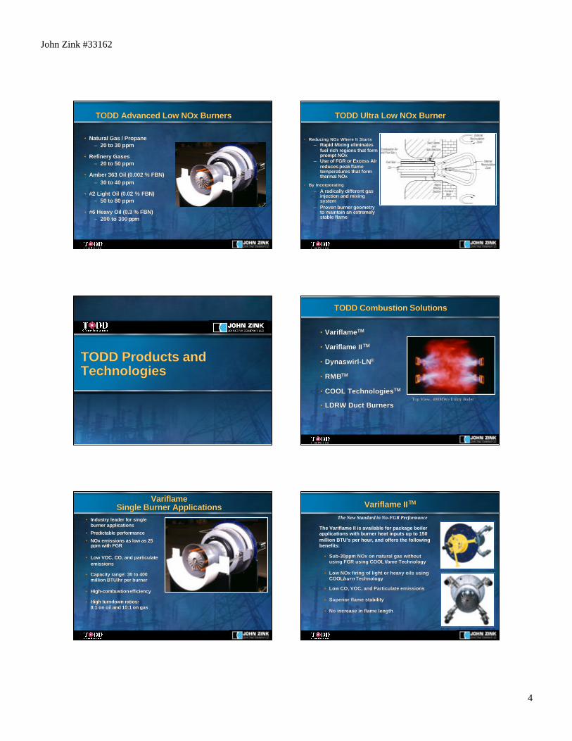
NOx Reduction MethodsNOx Reduction MethodsNOxNOx Control Technology Control Technology
0
20
40
60
80
100
120
140 N
Ox,
PP
M (C
orr.
3% O
xyge
n)
FLUE GAS RECIRCULATION
ADVANCED LOW NOx BURNER
STAGED COMBUSTION
CONVENTIONAL BURNERS
ULTRA LOW NOx BURNER
Staged Combustion Burner DesignStaged Combustion Burner Design
SecondaryAirPrimary
Air
TertiaryAir
Fuel Rich Zone
Staged air enters flameto complete burnout
Swirler imparts spin to primary airand creates recirculation zone
TODD Low NOx Burner Design FeaturesTODD Low NOx Burner Design Features
•• Gas staging techniquesGas staging techniques-- Gas injector design & orientation Gas injector design & orientation
•• Oil staging techniquesOil staging techniques-- Atomizer design & spray patterns Atomizer design & spray patterns
•• Flame stabilization techniquesFlame stabilization techniques- - Swirler design & orientationSwirler design & orientation
•• Air stagingAir staging-- Primary, Secondary, & Tertiary Air Primary, Secondary, & Tertiary Air locations and distribution locations and distribution
John Zink #33162
4
TODD Advanced Low NOx BurnersTODD Advanced Low NOx Burners
•• Natural Gas / PropaneNatural Gas / Propane–– 20 to 30 20 to 30 ppmppm
•• Refinery GasesRefinery Gases–– 20 to 50 20 to 50 ppmppm
•• Amber 363 Oil (0.002 % FBN)Amber 363 Oil (0.002 % FBN)–– 30 to 40 30 to 40 ppmppm
•• #2 Light Oil (0.02 % FBN)#2 Light Oil (0.02 % FBN)–– 50 to 80 50 to 80 ppmppm
•• #6 Heavy Oil (0.3 % FBN)#6 Heavy Oil (0.3 % FBN)–– 200 to 300 200 to 300 ppmppm
TODD Ultra Low NOx BurnerTODD Ultra Low NOx Burner
•• Reducing NOx Where It StartsReducing NOx Where It Starts–– Rapid Mixing eliminatesRapid Mixing eliminates
fuel rich regions that formfuel rich regions that formprompt NOxprompt NOx
–– Use of FGR or Excess AirUse of FGR or Excess Airreduces peak flamereduces peak flametemperatures that formtemperatures that formthermal NOxthermal NOx
•• By IncorporatingBy Incorporating–– A radically different gasA radically different gas
injection and mixinginjection and mixingsystemsystem
–– Proven burner geometryProven burner geometryto maintain an extremelyto maintain an extremelystable flamestable flame
TODD Products andTODD Products andTechnologiesTechnologies
TODD Combustion SolutionsTODD Combustion Solutions
•• VariflameVariflameTMTM
•• Variflame IIVariflame IITMTM
•• Dynaswirl-LNDynaswirl-LN®®
•• RMBRMBTMTM
•• COOL TechnologiesCOOL TechnologiesTMTM
•• LDRW Duct BurnersLDRW Duct BurnersTop View, 400 Top View, 400 MWeMWe Utility Boiler Utility Boiler
VariflameVariflameSingle Burner ApplicationsSingle Burner Applications
•• Industry leader for singleIndustry leader for singleburner applicationsburner applications
•• Predictable performancePredictable performance
•• NOx emissions as low as 25NOx emissions as low as 25ppm ppm with FGRwith FGR
•• Low VOC, CO, and particulateLow VOC, CO, and particulateemissionsemissions
•• Capacity range: 30 to 400Capacity range: 30 to 400million BTU/hr per burnermillion BTU/hr per burner
•• High-combustion efficiencyHigh-combustion efficiency
•• High turndown ratios:High turndown ratios:8:1 on oil and 10:1 on gas8:1 on oil and 10:1 on gas
Variflame IIVariflame IITMTM
•• Sub-30ppm NOx on natural gas withoutSub-30ppm NOx on natural gas withoutusing FGR using using FGR using COOLCOOL flameflame TechnologyTechnology
•• Low NOx firing of light or heavy oils usingLow NOx firing of light or heavy oils usingCOOLCOOLburnburn TechnologyTechnology
•• Low CO, VOC, and Particulate emissionsLow CO, VOC, and Particulate emissions
•• Superior flame stabilitySuperior flame stability
•• No increase in flame lengthNo increase in flame length
The New Standard in No-FGR Performance
The Variflame II is available for package boilerapplications with burner heat inputs up to 150million BTU’s per hour, and offers the followingbenefits:
John Zink #33162
5
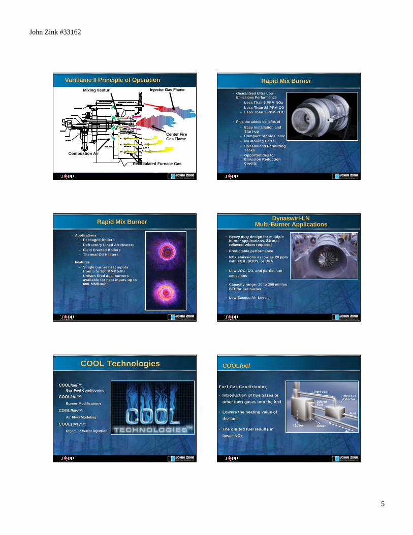
Variflame II Principle of OperationVariflame II Principle of OperationInjector Gas Flame
Center FireGas Flame
Recirculated Furnace Gas
Combustion Air
Mixing Venturi
Rapid Mix Burner Rapid Mix Burner
•• GuaranteedGuaranteed Ultra Low Ultra LowEmissions PerformanceEmissions Performance
–– Less Than 9 PPM NOxLess Than 9 PPM NOx–– Less Than 25 PPM COLess Than 25 PPM CO–– Less Than 3 PPM VOCLess Than 3 PPM VOC
•• Plus the added benefits ofPlus the added benefits of
–– Easy Installation andEasy Installation andStart-upStart-up
–– Compact Stable FlameCompact Stable Flame–– No Moving PartsNo Moving Parts–– Streamlined PermittingStreamlined Permitting
TasksTasks–– Opportunities forOpportunities for
Emission ReductionEmission ReductionCreditsCredits
Rapid Mix Burner Rapid Mix Burner
•• ApplicationsApplications–– Packaged BoilersPackaged Boilers–– Refractory Lined Air HeatersRefractory Lined Air Heaters–– Field Erected BoilersField Erected Boilers–– Thermal Oil HeatersThermal Oil Heaters
•• FeaturesFeatures–– Single burner heat inputsSingle burner heat inputs
from 5 to 300 from 5 to 300 MMBtuMMBtu/hr/hr–– Unison fired dual burnersUnison fired dual burners
available for heat inputs up toavailable for heat inputs up to600 MMBtu/hr600 MMBtu/hr
Dynaswirl-LNDynaswirl-LNMulti-Burner ApplicationsMulti-Burner Applications
•• Heavy duty design for multipleHeavy duty design for multipleburner applications. burner applications. StressStressrelieved when requiredrelieved when required
•• Predictable performancePredictable performance
•• NOx emissions as low as 20 NOx emissions as low as 20 ppmppmwith FGR, BOOS, or OFAwith FGR, BOOS, or OFA
•• Low VOC, CO, and particulateLow VOC, CO, and particulateemissionsemissions
•• Capacity range: 30 to 300 millionCapacity range: 30 to 300 millionBTU/hr per burnerBTU/hr per burner
•• Low Excess Air LevelsLow Excess Air Levels
COOLCOOLfuelfuelT MT M::Gas Fuel ConditioningGas Fuel Conditioning
COOLCOOLkitskitsTMTM::
Burner ModificationsBurner Modifications
COOLCOOLflowflowTMTM ::
Air Flow ModelingAir Flow Modeling
COOLCOOLspraysprayT MT M::
Steam or Water InjectionSteam or Water Injection
COOL TechnologiesCOOL Technologies
Fuel Gas Condit ioningFuel Gas Condit ioning
•• Introduction of flue gases orIntroduction of flue gases or
other inert gases into the fuelother inert gases into the fuel
•• Lowers the heating value ofLowers the heating value of
the fuelthe fuel
•• The diluted fuel results inThe diluted fuel results in
lower NOxlower NOx
COOLCOOLfuelfuel
Air
Fuel
Inert gas
Boiler Burner
COOLfuelEductor
DilutedFuel
John Zink #33162
6
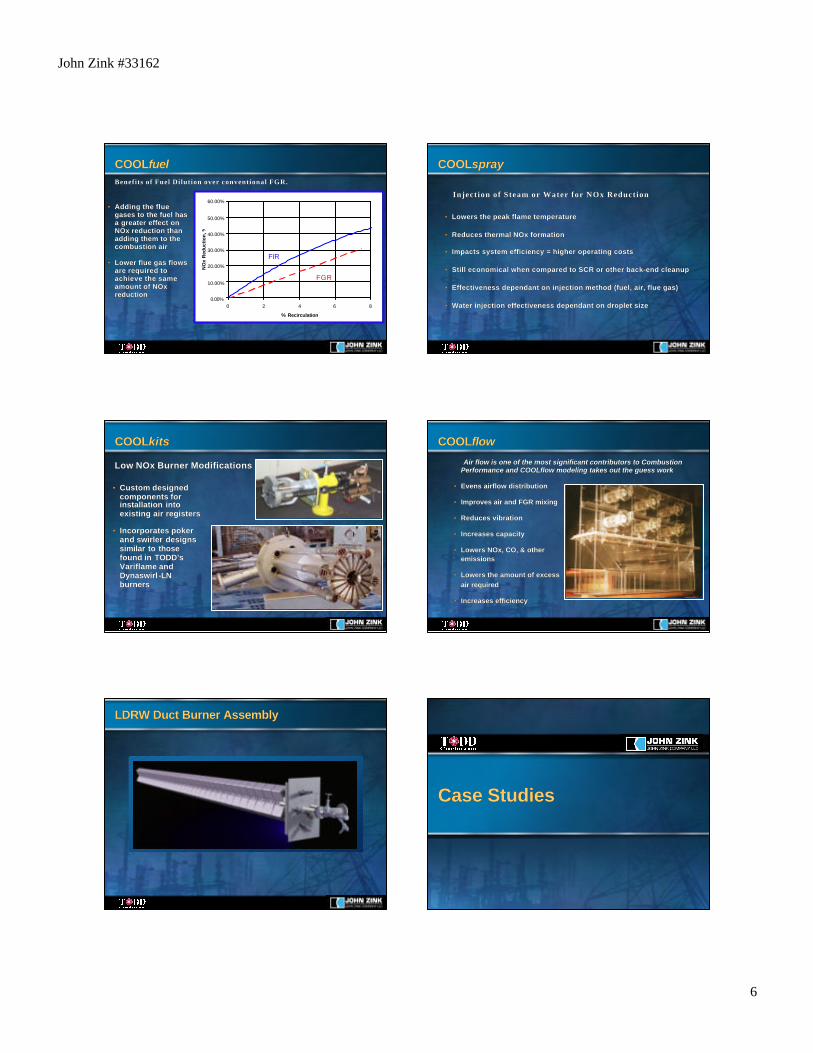
Benefits of Fuel Dilution over conventional FGR.Benefits of Fuel Dilution over conventional FGR.
•• Adding the flueAdding the fluegases to the fuel hasgases to the fuel hasa greater effect ona greater effect onNOx reduction thanNOx reduction thanadding them to theadding them to thecombustion aircombustion air
•• Lower flue gas flowsLower flue gas flowsare required toare required toachieve the sameachieve the sameamount of NOxamount of NOxreductionreduction
COOLCOOLfuelfuel
0.00%
10.00%
20.00%
30.00%
40.00%
50.00%
60.00%
0 2 4 6 8
% Recirculation
NO
x R
educ
tion,
%
FGR
FIR
•• Lowers the peak flame temperatureLowers the peak flame temperature
•• Reduces thermal NOx formationReduces thermal NOx formation
•• Impacts system efficiency = higher operating costsImpacts system efficiency = higher operating costs
•• Still economical when compared to SCR or other back-end cleanupStill economical when compared to SCR or other back-end cleanup
•• Effectiveness dependant on injection method (fuel, air, flue gas)Effectiveness dependant on injection method (fuel, air, flue gas)
•• Water injection effectiveness dependant on droplet sizeWater injection effectiveness dependant on droplet size
Inject ion of Steam or Water for NOx ReductionInject ion of Steam or Water for NOx Reduction
COOLCOOLsprayspray
Low NOx Burner ModificationsLow NOx Burner Modifications
COOLCOOLkitskits
•• Custom designedCustom designedcomponents forcomponents forinstallation intoinstallation intoexisting air registersexisting air registers
•• Incorporates pokerIncorporates pokerand and swirler swirler designsdesignssimilar to thosesimilar to thosefound in found in TODD’sTODD’sVariflame andVariflame andDynaswirlDynaswirl -LN-LNburnersburners
Air flow is one of the most significant contributors to Combustion Air flow is one of the most significant contributors to CombustionPerformance and COOLflow modeling takes out the guess workPerformance and COOLflow modeling takes out the guess work
•• Evens airflow distributionEvens airflow distribution
•• Improves air and FGR mixingImproves air and FGR mixing
•• Reduces vibrationReduces vibration
•• Increases capacityIncreases capacity
•• Lowers NOx, CO, & otherLowers NOx, CO, & otheremissionsemissions
•• Lowers the amount of excessLowers the amount of excessair requiredair required
•• Increases efficiencyIncreases efficiency
COOLCOOLflowflow
LDRWLDRW Duct Burner Assembly Duct Burner Assembly
Case StudiesCase Studies
John Zink #33162
7
Rapid Mix Burner Retrofit Case StudyRapid Mix Burner Retrofit Case Study
•• 100,000 lb/hr D-type package boiler100,000 lb/hr D-type package boiler
•• Natural gas firedNatural gas fired
•• Ambient combustion airAmbient combustion air
•• 23 - 28% FGR23 - 28% FGR
•• NOx less than 8.5 ppm across entireNOx less than 8.5 ppm across entireload rangeload range
•• CO less than 1 ppm across entire loadCO less than 1 ppm across entire loadrangerange
•• Excess O2 of 3.2 to 4.0%Excess O2 of 3.2 to 4.0%
•• Boiler capacity increased to 110,000Boiler capacity increased to 110,000lb/hrlb/hr
Furnace view of a Rapid Mix Burner
COOLCOOLfuelfuel
165 MW tangentially fired utility boiler retrofit (CS 117)165 MW tangentially fired utility boiler retrofit (CS 117)
Boiler Type: Combustion EngineeringBoiler Type: Combustion Engineering
Boiler Size: 165 MWeBoiler Size: 165 MWe
Steam Flow: 1,200,000 PPHSteam Flow: 1,200,000 PPH
Burner Type: CE Tilting TangentialBurner Type: CE Tilting Tangential
# Burners/Boiler: 40# Burners/Boiler: 40
Heat Input: 40 Heat Input: 40 MMBtuMMBtu/hr/hr
Comb. Air Temp: 540 deg FComb. Air Temp: 540 deg F
Fuel: Natural GasFuel: Natural Gas
NOx - base: 132 ppmNOx - base: 132 ppm
COOLCOOLfuel fuel NOx: 33 ppmNOx: 33 ppm
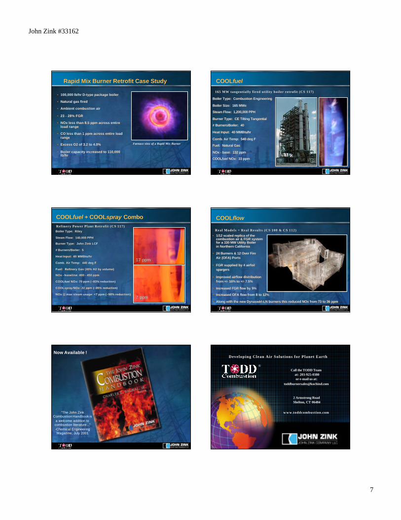
Boiler Type: RileyBoiler Type: Riley
Steam Flow: 140,000 PPHSteam Flow: 140,000 PPH
Burner Type: John Zink LCFBurner Type: John Zink LCF
# Burners/Boiler: 5# Burners/Boiler: 5
Heat Input: 40 Heat Input: 40 MMBtuMMBtu/hr/hr
Comb. Air Temp: 440 deg FComb. Air Temp: 440 deg F
Fuel: Refinery Gas (40% H2 by volume)Fuel: Refinery Gas (40% H2 by volume)
NOx - baseline: 400 - 450 ppmNOx - baseline: 400 - 450 ppm
COOLCOOLfuel fuel NOx: 70 ppm (~83% reduction)NOx: 70 ppm (~83% reduction)
COOLCOOLspray spray NOx: 22 ppm (~95% reduction)NOx: 22 ppm (~95% reduction)
NOx @ max steam usage: <7 ppm (~98% reduction)NOx @ max steam usage: <7 ppm (~98% reduction)
Refinery Power Plant Retrofit (CS 117)Refinery Power Plant Retrofit (CS 117)
COOLCOOLfuel fuel + COOL+ COOLspray spray ComboCombo
17 ppm17 ppm
7 ppm7 ppm
COOLCOOLflowflow
Real Models = Real Results (CS 108 & CS 112)Real Models = Real Results (CS 108 & CS 112)
•• 1/12 scaled replica of the1/12 scaled replica of thecombustion air & FGR systemcombustion air & FGR systemfor a 330 MW Utility Boilerfor a 330 MW Utility Boilerin Northern Californiain Northern California
•• 24 Burners & 12 Over Fire24 Burners & 12 Over FireAir (OFA) PortsAir (OFA) Ports
•• FGR supplied by 4 airfoilFGR supplied by 4 airfoilspargersspargers
•• Improved airflow distributionImproved airflow distributionfrom +/- 16% to +/- 7.5%from +/- 16% to +/- 7.5%
•• Increased FGR flow by 5%Increased FGR flow by 5%
•• Increased OFA flow from 8 to 12%Increased OFA flow from 8 to 12%
•• Along with the new Dynaswirl-LN burners this reduced NOx from 73 to 36 ppmAlong with the new Dynaswirl-LN burners this reduced NOx from 73 to 36 ppm
Now Available !
“The John ZinkCombustion Handbook is
a welcome addition tocombustion literature...”-Chemical EngineeringMagazine, July 2001
Call the TODD Team at: 203-925-0380or e-mail us at:
2 Armstrong RoadShelton, CT 06484
w w w .toddcombustion.com
Developing Clean Air Solutions for Planet EarthDeveloping Clean Air Solutions for Planet Earth
®