Embed Size (px)
Citation preview

�
JM3620SH Instructions Manual
identification
Authorized Distributor
Owner:...................................................................................................
.................................................................................................................
Address....................................................................................................
.........................................................................................Nº ....................
Phone .................................................................................
City ..............................................................................State ...................
Zip Code .................................- .........
Machine Model ........................................................................................
Serial Number ..........................................................................................
Year of Manufacture ................................................................................
Invoice Nº ................................................................................................
Date ........ / ........ / .........

�
JM3620SH Instructions Manual
WaRRantY ceRtificate
�. JUStino de MoRaiS, iRMÃoS S/a – JUMiL, guarantees that the agricultural instruments and their respective parts, manufactured by JUMiL itself, herein simply referred to as PRodUct, are free of manufacturing or material quality defects.
�. The issues pertaining to the granting of Warranty will obey the following
principles:
2.1. The warranty contained in this Certificate will be valid: a) For the period of six (6) months, beginning from the date of the
effective delivery of the PRodUct to the farmer; b) Only for a brand new PRodUct directly purchased by the farmer
from an Authorized Dealer or JUMiL, with the exception of what is defined in item �.3.
�.�. With the exception of the following sub item, the Warranty granted to the farmer will be provided through an Authorized JUMiL Dealer.
�.3. If the PRodUct is sold to the farmer by a dealer that is not an Authorized JUMiL Dealer, the Warranty right shall subsist, and therefore be directly claimed before JUMiL, pursuant to the terms of this Certificate.
�.4. The warranty shall not be granted in the event of any damage to the
PRodUct or its performance caused by: a) Operator negligence, imprudence or lack of skill; b) Failure to obey use and maintenance instructions and
recommendations contained in the Instructions Manual.
�.5. Likewise, the Warranty shall not be granted if the PRodUct, after sold, undergoes any transformation or modification, or is employed for any purposes other than the ones for which the PRodUct is originally destined.
�.6. The PRodUct, when changed or substituted under this Warranty
shall be of the property of JUMiL, and must be surrendered, upon fulfillment of the applicable legal requirements.
2.7. In the fulfillment of its policy toward permanent evolution, JUMiL subjects its products to constant improvements or modifications, without such fact constituting in JUMiL’s obligation to extend said improvements / modifications to previously sold products or models.
�.8. JUMiL will not be liable to pay indemnities of any kind in respect to harvest losses resulting from the inadequate setting of devices comprising the product in relation to the distribution of seeds or fertilizer.
3
JM3620SH Instructions Manual
taBLe of contentS
� - INTRODUCTION ......................................................................................... 4� - PRODUCT PRESENTATION ....................................................................... 53 - SAFETY NORMS ......................................................................................... 64 - TECHNICAL FEATURES ............................................................................��5 - BALLASTING THE TRACTOR’S FRONT .................................................. �36 - COUPLING THE IMPLEMENT TO THE TRACTOR .................................. �47 - LEVELING ................................................................................................. �58 - PREREQUISITES AND GENERAL RECOMMENDATIONS ..................... �69 - SETTINGS AND OPERATIONS ................................................................ �69.� - COVERER DISk ANGLE ........................................................................... �69.� - DISTANCE BETWEEN THE DISkS .......................................................... �6�0 - ASSEMBLY ................................................................................................ �7�0.� - HOSE ASSEMBLY ..................................................................................... �7�� - GENERAL INFORMATION ON THE SPRAYING SYSTEM ...................... �8�� - CAUTIONS WHEN USING PHYTOSANITARY PRODUCTS .................... ���3 - LUBRICATION ........................................................................................... ���3.� - LUBRICATION SYMBOLOGY ................................................................... ���3.� - LUBRICATION TABLE ............................................................................... �3�3.3 - LUBRICATION POINTS ............................................................................. �4

4
JM3620SH Instructions Manual
1- intRodUction
Congratulations, you have purchased an implement manufactured with the latest technology and efficiency available in the market, guaranteed by the renowned brand JUMIL.
The purpose of this manual is to guide you in the correct operation of this product, allowing you to obtain the best performance and benefits from the equipment. It is for this reason that we recommend you read this manual carefully before starting to use it.
keep this manual in a secure location for easy consultation.JUMIL and its dealer network will always be ready to provide you
with the required technical clarifications and orientations needed for your equipment.
Phone: ( �6)3660- �000Fax: ( �6)3660- ���6
www.jumil.com.br

5
JM3620SH Instructions Manual
2- PRodUct PReSentation
JM3620SH is an implement intended to cover post-planting sugarcane tholepins and at the same time apply insecticide in two lines, working coupled to the tractor’s three-point hydraulic system.
The coverer assembly is made up of a tool carrier-bar, �8” pantographic plain concave coverer disks that cover the furrows and oscillating harrowing or compacter rollers that promote adequate contact with of the earth with the tholepins and eliminate air bags that impair budding.
The insecticide applier assembly is made up of a polyethylene tank with capacity of 300 liters, gage, filter, piston-diaphragm mechanical pump or diaphragm electropump with manometer and pressure regulator, anti-drip nozzles and agitation system, allowing uniform and homogeneous application.

6
JM3620SH Instructions Manual
3 – SafetY noRMS
Incorrect use of this equipment may result in serious or even fatal accidents. Before putting the implement into operation, carefully read this manual as well as the tractor’s manual. Ensure that the person responsible for the operation has been instructed on the correct, safe use of the implement, having read and understood this machine’s manual. In special, use all Individual Protection Equipment required for your safety.
important notes:- General:
�) All machinery and/or equipment should be solely used for their original purposes, according to the technical specifications in the manual;
�) The manuals of machines, equipment and implements should be kept in the establishment and the employer should inform operators of its content and provide them whenever required;
3) Do not run the equipment in closed, non-ventilated places. Gases released from the tractor engine are highly hazardous;
4) Only skilled and qualified operators should operate agricultural machinery and equipment. Under no circumstance allow minors to operate them;
5) Only use machinery, equipment and implements with protected power transmissions;
6) Never carry out repair or maintenance under the machine while suspended by the hydraulic system only. Ensure that it is perfectly wedged and stationary;
7) The transmission protectors or removable articulations can only be removed for cleaning, lubrication, repair and adjustment, after which they should be put back. Cleaning, lubrication, loading and maintenance is forbidden while the equipment and implements are operating, except if this is essential to perform these operations, when special protection and signaling measures against occupational accidents should be taken;
8) It is prohibited, under any circumstance, to carry people on motorized machinery and equipment and on attached implements;
9) Do not wear loose or very baggy clothes to prevent them from tangling up with projections and moving machine parts (cardan shaft, belts, chains or gear in motion);
�0) On coupling and decoupling the equipment, use adequate IPE(s) (protection gloves);
��) When placing equipment in motion after each repair, ensure that the parts are well fastened and that all machine parts are moving properly, especially those repaired. Ensure also that no one is close to the

7
JM3620SH Instructions Manual
the equipment and that no tools were forgotten under, on or inside it;��) keep the belt and transmission locations free in general;�3) On raising and lowering the equipment, check if there are no
people or animals near;�4) keep children, animals and watchers at a safe distance. Never
allow anyone to walk unaccompanied behind, beside or in front of the moving equipment;
�5) Use speed that suits the land conditions or paths to be taken. Be careful with uneven terrains and reduce the speed at curves;
�6) Carefully check the transport width in narrow places;�7) When circulating with the machine on roads, observe the laws/
norms of the State – consult the Road Traffic Authority or State/Federal Highway Police Department;
�8) Have full knowledge of the terrain before beginning the work. Demarcate dangerous places or places with obstacles;
- Specific:
�) Pay attention on getting close to the cutting disks and equipment articulating parts;
�) Never climb the equipment, even when it is stationary;3) During the work, use individual protection equipment – IPE (PVC
coat, gloves and rubber boots, safety goggles and mask against possible vapors). Replace it immediately in case of contamination;
4) Never work alone when handling toxic products;5) Preparing the syrup requires much caution because it is when the
product is in its highest concentration. On preparing the syrup, seek a fresh and ventilated place, always with your back to the wind;
6) Read and follow the instructions in the product labels carefully;7) Open the packaging carefully to prevent spilling the product.8) Right after emptying the packaging, proceed to “threefold washing”
(see note below), thus preventing environmental contaminations and health risks to people;
9) After preparing the syrup, wash the utensils and dry them in the sun;
�0) Always use clean water to prepare the syrup and prevent clogging of the sprayer nozzles;
��) Avoid inhaling, splashing and contact with the products;��) Do not eat, drink or smoke when handling or applying the
product;13) Never unclog nozzles, orifices, valves, piping using the mouth;�4) Prepare only the amount of syrup required for use in a maximum
of one run;
8
JM3620SH Instructions Manual
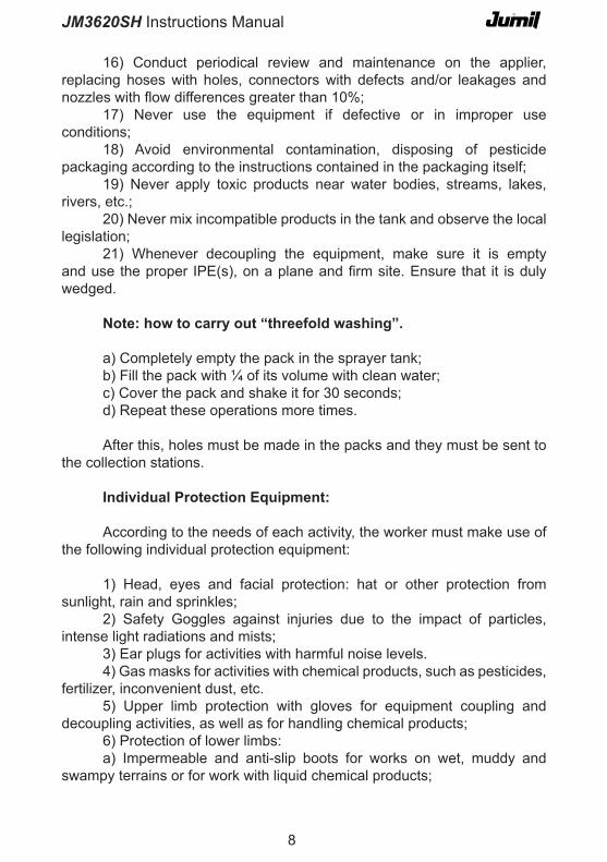
�6) Conduct periodical review and maintenance on the applier, replacing hoses with holes, connectors with defects and/or leakages and nozzles with flow differences greater than 10%;
�7) Never use the equipment if defective or in improper use conditions;
�8) Avoid environmental contamination, disposing of pesticide packaging according to the instructions contained in the packaging itself;
�9) Never apply toxic products near water bodies, streams, lakes, rivers, etc.;
�0) Never mix incompatible products in the tank and observe the local legislation;
��) Whenever decoupling the equipment, make sure it is empty and use the proper IPE(s), on a plane and firm site. Ensure that it is duly wedged.
note: how to carry out “threefold washing”.
a) Completely empty the pack in the sprayer tank;b) Fill the pack with ¼ of its volume with clean water;c) Cover the pack and shake it for 30 seconds;d) Repeat these operations more times.
After this, holes must be made in the packs and they must be sent to the collection stations.
individual Protection equipment:
According to the needs of each activity, the worker must make use of the following individual protection equipment:
�) Head, eyes and facial protection: hat or other protection from sunlight, rain and sprinkles;
�) Safety Goggles against injuries due to the impact of particles, intense light radiations and mists;
3) Ear plugs for activities with harmful noise levels.4) Gas masks for activities with chemical products, such as pesticides,
fertilizer, inconvenient dust, etc.5) Upper limb protection with gloves for equipment coupling and
decoupling activities, as well as for handling chemical products;6) Protection of lower limbs:a) Impermeable and anti-slip boots for works on wet, muddy and
swampy terrains or for work with liquid chemical products;

9
JM3620SH Instructions Manual
b) Boots with reinforced toecap for jobs involving risk of heavy materials and objects dropping;
c) Long boots or boots with gaiters for activities involving risk of poisonous animal attacks.
The Worker should wear the Individual Protection Equipment indicated for the respective tasks in order to protect them.
NOTE: All IPEs purchased must come with Approval Certificate issued by the Brazilian Ministry of Labor and Employment with effective validity.
transport on truck/Wagon
�) Transport over long distance must be on truck, wagon, etc… according to these safety instructions:
a) Use suitable hoists or ramps to load and offload the machine. Do not load in steep banks due to risk of serious accidents;
b) Wedge the equipment properly;c) Use ties (cables, chains, ropes, etc) in enough quantity to render
the equipment immobile during transport;d) Check the cargo’s conditions after the first 8 to 10 kilometers
of travel, then after every 80 to �00 kilometers, check if the ties are not becoming slack. Check the cargo with more frequency on roads that are not tarred or full or holes;
e) Be attentive always. Be carefully with the transport height, especially under the electric power network, viaducts, etc;
f) Always check the effective legislation on the height and cargo width limits. If necessary, use flags, lights and reflectors to warn other drivers.

�0
JM3620SH Instructions Manual
Check and fulfill nR 31 – Regulatory norm of Safety ad Health at Work in agriculture, Livestock, forestry, forest exploration and aquiculture (Executive Ruling No. 86, 03/03/05 – Federal gazette of 04/Mar/05), which is aimed at establishing the precepts to be followed in the organization and in the work environment in order to match planning and development of agriculture, livestock, forestry, forest exploration and aquiculture with safety and health and the work environment.
attention MR. oWneR

��
JM3620SH Instructions Manual
4 – tecHnicaL featUReS
(*) The nozzles do not come with the machine; they must be purchased according to agronomical instruction.
Control proportional to the speed, permanent agitation, self-sealing filter, anti-spinning.
Has auxiliary cooling fan.
c-a12 / c-a13 c-a12 / c-a13 c2 / c3 c2 / c3W/ Roller W/ o Roller W/ Roller W/o Roller
Numer of Lines � or 3 � or 3 � or 3 � or 3CouplingSpacingDriveTank Capacity - -Nozzle carrier (*) Anti-drip with quick coupling - -
Minimum power requiredWork speed 8 km/hr
�8" pantographic plain concave (�/line), with lateral distance and cutting angle settingCoverer Disks
Harrowing (satandard) or
Compacter (optional)
Roller -
Harrowing (standard) or Compacter (optional)
-
Model
3-Point hidraulic system�,30 to �,50 m
Mechanical or electrical300 liters (with gage)
65 hp (�lines) and 75 hp (3 lines)
CouplingPowerFlowMaximum Working PressureWorking Rotation
Mechanical PumpAt the power socket, without use of cardan
0,9 hp�3 to �9 l/min
��7 psi (�5 bar)400 to 550 rpm
electrical PumpCouplingVoltageFlowMaximum Working PressureMaximum Working Pressure RecommendedAutomatic turn off pressure
Mountd in the chassis�� or �4 V DC with protective fuse
�3 a �9 l/min40 psi (�,8 bar)�5 psi (�,8 bar)
45 psi
Harrowing
(standard) or Compacter (optional)
At the power take-off, without use of cardan

��
JM3620SH Instructions Manual
dimensions
��70
�5�0
0900
0490
�7�0

�3
JM3620SH Instructions Manual
5 - BaLLaStinG tHe tRactoR’S fRont
Working with an implement installed in the three-point hydraulic system, as is the case of system of JM36�0SH, it is absolutely natural for the tractor’s front, in given circumstances, to tend to lift off the ground. To compensate this tendency, you must ballast the tractor’s front, preferably using the already existing support and original ballasts. Do not place weights on the front wheels. A practical way of determining the amount of ballasts is as follows:
Without the coupled implement, weigh on a scale only the tractor front axle. After coupling the implement, put it in transport position (fully lifted by the hydraulic system) and weigh the front axle again. Install the necessary number of weights to obtain at least over half of the initial weight.
This procedure is essential to guarantee good drivability of the tractor, facilitating following of the line and preventing the implement from leaving failures.
The placing of frontal weights does not always keep the tractor properly balanced, especially if driven too fast on an uneven terrain and with the implement in transport position. Be prudent and drive slowly, especially under such conditions.
Fig. 00�
attention
�4
JM3620SH Instructions Manual
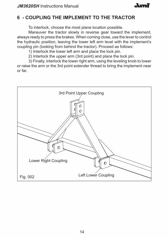
6 - coUPLinG tHe iMPLeMent to tHe tRactoR
To interlock, choose the most plane location possible.Maneuver the tractor slowly in reverse gear toward the implement,
always ready to press the brakes. When coming close, use the lever to control the hydraulic position, leaving the lower left arm level with the implement’s coupling pin (looking from behind the tractor). Proceed as follows:
�) Interlock the lower left arm and place the lock pin.�) Interlock the upper arm (3rd point) and place the lock pin.3) Finally, interlock the lower right arm, using the leveling knob to lower
or raise the arm or the 3rd point extender thread to bring the implement near or far.
3rd Point Upper Coupling
Lower Right Coupling
Left Lower CouplingFig. 00�

�5
JM3620SH Instructions Manual
7 - LeVeLinG
For a perfect operation, the JM3620SH must be level in both directions. Level using the 3rd point arm and knob of the tractor’s right lower arm, such that when looking from the side and back, the lower line of the front pipe of the implement is horizontal.
After leveling, you must adjust the stabilizers so as to remove the gap between the implement and tractor. This procedure is essential to assure stability and quick response of the implement to the tractor’s movements. Proceed as follows:
�) Lift the implement completely;�) Try to keep an equal distance between the lower arms and tires
from both sides;3) Adjust the stabilizers until all the gap between the implement and
tractor is removed.
Never adjust the stabilizers when the implement is lowered because they may be damaged on lifting them.
“A” “A”
Fig. 003
attention
�6
JM3620SH Instructions Manual
8 – PReReQUiSiteS and GeneRaL RecoMMendationS
Before putting the implement into operation, check if the settings are correct and if all the components are duly mounted and fixed.
Check if the pump, control and respective hoses and connections are duly coupled and free of leaks.
Ensure that you are using the Individual Protection Equipment (IPE) recommended for the work.
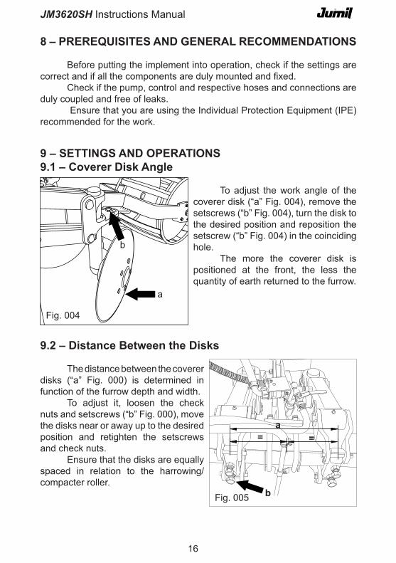
9 – SettinGS and oPeRationS9.1 – coverer disk angle
To adjust the work angle of the coverer disk (“a” Fig. 004), remove the setscrews (“b” Fig. 004), turn the disk to the desired position and reposition the setscrew (“b” Fig. 004) in the coinciding hole.
The more the coverer disk is positioned at the front, the less the quantity of earth returned to the furrow.
a
b
Fig. 004
9.2 – distance Between the disks
The distance between the coverer disks (“a” Fig. 000) is determined in function of the furrow depth and width.
To adjust it, loosen the check nuts and setscrews (“b” Fig. 000), move the disks near or away up to the desired position and retighten the setscrews and check nuts.
Ensure that the disks are equally spaced in relation to the harrowing/compacter roller.
Fig. 005 b
a= =

�7
JM3620SH Instructions Manual
10 - aSSeMBLY10.1 – Hose assembly
Follow the diagram below to assembly the circuit of connections and hoses.
Blu
e �”
Blu
e �”
Ora
nge
�/�
”
Ora
nge
3/4
”
Blu
e 3/
4”
Fig.
006

�8
JM3620SH Instructions Manual
drive by diaphragm electropump:
The diaphragm electropump (Flojet QUAD 4300 model) used by JM36�0SH is of the positive displacement and self-priming type. It can be mounted up to 2.4 m above the level of the fluid it will pump normally, provided there is no air inlet at any point of the suction line.
electrical connection
Connect the red wire (+) and black wire (-) of the pump power cable to the respective red and black wires connected to the positive and negative terminals of the tractor battery. Position the on/off switch in a place of easy access on the tractor dashboard. Said switch has a �5A fuse to protect the pump from a possible short circuit in the tractor electric system.
11- GeneRaL infoRMation on tHe SPRaYinG SYSteM
In addition to this manual, you also received a specific manual on the pump and control supplied by the manufacturer. It is very important that you read them for correct use and maintenance, thus obtaining a good performance and long service life of the equipment.
drive by Piston-diaphragm Mechanical Pump:
The piston-diaphragm mechanical pump (Comet BP �0/�5 model) used by the JM3620SH is equipped with a pressure accumulator, whose function is to minimize the intermittence (pulsation) in the sprayer nozzles. Its pressure is determined in function of the pressure range in which the pump will operate, and must be adjusted and checked regularly using a compressed air system and manometer like the one used to calibrate tires, observing the table below.
bar psi bar psi� to 5 �9 to 73 � �95 to �0 73 to �45 � to 5 �9 to 73�0 to �0 �45 to �90 5 to 7 73 to �0�
PUMP Working Pressure ACCUMULATOR Inflation Pressure

�9
JM3620SH Instructions Manual
Useful equations
�) speed (km/h) =Distance Covered (m) x 3.6
Time taken (s)
Example: 50m x 3,6 = �0 km/h�8 s
choosing the Spraying nozzles (tips)
The application equipment has the function of distributing the spraying accurately on the target. However, many factors interfere negatively in the spraying quality, the most important of which are improper calibration of the equipment, lack of control of size and distribution of the sprayed drops, improper volume of application, faulty covering on the target, improper height of the spraying bar, time of application and incorrect choice of the nozzles.
Practical method for calibration
� – Fill the sprayer at least up to half of its capacity;� – Measure and note down the time required for the tractor to cover 50
meters in the gear and acceleration of desired works. Repeat the operation to obtain the average;
3 – Calculate the speed according to equation �;4 – Obtain the following informations:- The type of nozzle used, ensuring that they are all equal;- The volume to be applied (l/ha);- The speed obtained in item 3;- The spacing between nozzles (m);5 – Calculate the quantity (l/min) per nozzle according to equation �;6 – Ensure that the sprayer is free of leaks or clogs and that all the
components are duly mounted and in perfect state;7 – Turn on the sprayer and collect the volume applied in � nozzle for
� minute, adjusting the pressure and repeating collection until the quantity determined by equation � is obtained;
8 – Ensure that the final working pressure is within the admissible range for the type of nozzle and pump used. Use a larger nozzle if the pressure is too high.

�0
JM3620SH Instructions Manual
�) quantity/nozzle (l/min) =
Quantity x Speed x Distance between Nozzles
600Exemple: �90 l/ha x �0 km/h x �,50 m = 4,75 l/min/nozzle
600
Nozzle Identification (Nomenclature)
XR TEEJET
��004VS
Fig. 007

��
JM3620SH Instructions Manual
12- caUtionS WHen USinG PHYtoSanitaRY PRodUctS
It is very important to read the following information carefully because they give the cautions to be taken when using phytosanitary equipment. This information was generated by Embrapa Sistemas de Produção and can be obtained at the website http://sistemasdeproducao.cnptia.embrapa.br/
calibrating the Sprayer
Calibration is fundamental for correct application of pesticides. Once the sprayer has been coupled and supplied with water, check the system’s operation, if there are no leakages, and if the components are functioning satisfactorily.
Equipping the sprayer with appropriate nozzles is one of the most crucial points in this phase. The sprayer must be taken up to the worksite and several nozzle options must be tested to decide on the one that best meets the treatment requisites, that is, the one that best places the product on the target, without loss by run off by drifting.
The components of the equipments to be considered to improve quality and efficiency in the phytosanitary treatments are as follows:
nozzles – preferably use ceramic nozzles, due to the greater resistance, durability and quality of the drops. It is regarded as the foremost organ of the sprayer because the flow and quality of the drops depend on it. It has an average durability of 400 hours with �50 to �00 pounds of pressure.
filter – use filters in the tank inlets, before the pump and before the nozzles, to prevent wear and/or clogging. The filter at the tank inlet must be cleaned often, at least daily;
agitators – after diluting the products, it is necessary that the syrup remains homogenized during spraying, for uniform distribution of the product on the plant, and the flow must not be greater than 8% of the pump capacity. The agitator is essential when working with products in the form of wettable powder or concentrated suspension;
Manometer – used to check the exit pressure of the syrup through the nozzles. Must have visible scale and be bathed in glycerin for greater resistance. The ordinary manometer has durability problems because it lacks the robustness to support the harsh work conditions (vibration and aggressive liquid circulating in its interior). Excess pressure in the pump causes drifting and loss of the spraying syrup;

��
JM3620SH Instructions Manual
13 - LUBRication
JM3620SH was designed to require minimal lubrication. However, this is necessary and essential in some parts for good functioning and greater service life of the implement.
Below are the lubrication symbols, recommended lubricant table with the equivalent specification of several manufacturers and indication of lubrication points and intervals.
Before beginning lubrication, clean the grease fittings and replace the damaged ones.13.1 - Lubrication Symbology
Lubricate with lithium soap-based grease, NLGI-� consistence in the recommended intervals.
Lubrication intervals in worked hours
Oil Gage: Check the oil level after the first 10 hours of work, period of the pump’s breaking in and top up if necessary.
This operation must be done with the machine leveled, use ISO VG �50 (SAE 40) oil or equivalent.
Oil Change: Change the oil after 300 hours of work.
attention

�3
JM3620SH Instructions Manual
13.2
– L
ubric
atio
n ta
ble

�4
JM3620SH Instructions Manual
Fig.
008
Fig.
009
Fig.
0�0
13.3 – Lubrication Points

�5
JM3620SH Instructions Manual
Fig. 009
30
Fig. 008
30
30
Fig. 0�0
Coverer DiskDisk Cart
Harrowing Disk
The pump’s oil gage must be checked periodically, and must not be below the level mark, if necessary, top up with ISO VG 50 (SAE 40) mineral oil. If oil leaks from the pump, it must be repaired immediately to prevent damages to the internal components. The pump must not work with rotation greater than 540 rpm and also, it must not work without the syrup in the tank. Not observing this recommendation can lead to serious damages in the pump.
Fig. 0��
Pump
The pump must not work with endoSULfan-based products, which causes chemical attack on the equipment’s plastic and rubber parts.
attention

�6
JM3620SH Instructions Manual
Possible cause Solution�- Lack of syrup in the tank; �- Put syrup in the tank.�- Line meter closed; � – Open meter.
4 – Clogged hoses or nozzles; 4 – Disassemble and clean.
Unable to spray
3- Remove sedimented product and do not leave product in the tank after the work.
3 - Product sediment at bottom of tank;
Possible cause SoluçãoSolution
3 – Problem in the pump valves; 3 – Check internal parts of the valve.
�- Rupture of the pump diaphragm; � – Check the pump.
� – Problem in the spray control; � – Check internal parts, repairs, springs, etc.
Lack of Pressure in the Spraying System
Possible cause Solution
� – Identify and remove leakage in the entire circuit.� – Problems with leakage;
3 – Check if there is any object obstructing passage of liquid to the pump.
3 - Problems with the pump;
irregular flow
� – Object obstructing the hose with curve or fold; � – Check the pump exit hoses.
�7
JM3620SH Instructions Manual
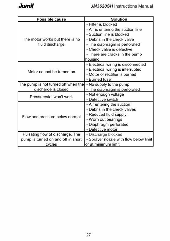
Possible cause Solution - Filter is blocked - Air is entering the suction line - Suction line is blocked - Debris in the check valve - The diaphragm is perforated - Check valve is defective
- Electrical wiring is disconnected - Electrical wiring is interrupted - Motor or rectifier is burned - Burned fuse - No supply to the pump - The diaphragm is perforated - Not enough voltage - Defective switch - Air entering the suction - Debris in the check valves - Reduced fluid supply; - Worn out bearings - Diaphragm perforated - Defective motor - Discharge blocked
Pressurestat won’t work
Flow and pressure below normal
- Sprayer nozzle with flow below limit or at minimum limit
Pulsating flow of discharge. The pump is turned on and off in short
cycles
The motor works but there is no fluid discharge
Motor cannot be turned on
The pump is not turned off when the discharge is closed
- There are cracks in the pump housing

�8
JM3620SH Instructions Manual
notes