Embed Size (px)
Citation preview
August 31, 2007
Mr. Peter DietrichSite Vice President Entergy Nuclear NortheastJames A. FitzPatrick Nuclear Power PlantPost Office Box 110Lycoming, NY 13093
SUBJECT: JAMES A. FITZPATRICK NUCLEAR POWER PLANT - NRC COMPONENTDESIGN BASES INSPECTION REPORT NO. 05000333/2007006
Dear Mr. Dietrich:
On July 19, 2007, the U.S. Nuclear Regulatory Commission (NRC) completed an inspection atthe James A. FitzPatrick Nuclear Power Plant. The enclosed inspection report documents theinspection results, which were discussed on July 19, 2007, with you and other members of yourstaff.
The inspection examined activities conducted under your license as they relate to safety andcompliance with the Commission’s rules and regulations and with the conditions of your license. In conducting the inspection, the team examined the adequacy of selected components andoperator actions to mitigate postulated transients, special initiating events, and design basisaccidents. The inspection also reviewed Entergy’s response to selected operating experienceissues. The inspection involved field walkdowns, examination of selected procedures,calculations and records, and interviews with station personnel.
This report documents two findings of very low safety significance (Green), both of whichinvolved violations of NRC requirements. However, because of their very low safetysignificance and because the issues have been entered into your corrective action program, theNRC is treating the issues as non-cited violations (NCVs), in accordance with Section VI.A.1 ofthe NRC's Enforcement Policy. If you contest any NCV in this report, you should provide aresponse with the basis for your denial, within 30 days of the date of this inspection report, tothe U.S. Nuclear Regulatory Commission, ATTN: Document Control Desk, Washington, D.C. 20555-0001; with copies to the Regional Administrator, Region I; the Director, Office ofEnforcement, U.S. Nuclear Regulatory Commission, Washington, D.C. 20555-0001; and theNRC Resident Inspector at the James A. FitzPatrick Nuclear Power Plant.
P. Dietrich 2
In accordance with 10 CFR 2.390 of the NRC’s “Rules of Practice,” a copy of this letter and itsenclosures, and your response (if any) will be available electronically for public inspection in theNRC Public Document Room or from the Publicly Available Records (PARS) component of theNRC’s document system (ADAMS). ADAMS is accessible from the NRC Web site at http://www.nrc.gov/reading-rm/adams.html (the Public Electronic Reading Room).
Sincerely,
/RA/
Lawrence T. Doerflein, ChiefEngineering Branch 2Division of Reactor Safety
Docket No.: 50-333License No.: DPR-59
Enclosure: Inspection Report No. 05000333/2007006w/Attachment: Supplemental Information
SUNSI Review Complete: LTD (Reviewer’s Initials)ADAMS ACC#ML072430509
DOCUMENT NAME: C:\FileNet\ML072430509.wpdAfter declaring this document “An Official Agency Record” it will be released to the Public.To receive a copy of this document, indicate in the box: "C" = Copy without attachment/enclosure "E" = Copy with attachment/enclosure "N" = No copy
OFFICE RI:DRS RI:DRS RI:DRP RI:DRS
NAME JSchoppy/LTD for WSchmidt/WLS ECobey/EWC LDoerflein/LTDDATE 08/29/07 08/29/07 08/30/07 08/31/07
OFFICE
NAMEDATE
OFFICIAL RECORD COPY

P. Dietrich 3
cc w/encl:G. J. Taylor, Chief Executive Officer, Entergy Operations J. Wayne Leonard, Chairman & CEO, Entergy OperationsM. R. Kansler, President & CEO / CNO, Entergy Nuclear Operations, Inc.J. T. Herron, Senior Vice President, Entergy OperationsM. Balduzzi, Senior Vice President, Northeastern Regional OperationsSenior Vice President of Engineering and Technical ServicesJ. DeRoy, Vice President, Operations SupportK. Mulligan, General Manager, Plant OperationsO. Limpias, Vice President, Engineering (ENO)J. Ventosa, General Manager, Engineering (ENO)J. McCann, Director, Nuclear Safety and Licensing (ENO)C. Faison, Manager, Licensing (ENO)E. Harkness, Director of Oversight (ENO)Director, Nuclear Safety AssuranceJ. Costedio, Manager, Licensing W. Dennis, Assistant General Counsel (ENO)M. Balboni, Deputy Secretary, New York State Energy Research and Development Authority P. Eddy, New York State Department of Public Service P. Smith, President, New York State, Energy, Research, and Development AuthorityS. Lyman, Oswego County AdministratorSupervisor, Town of ScribaC. Donaldson, Esquire, Assistant Attorney General, New York Department of LawJ. Sniezek, PWR SRC ConsultantM. Lyster, PWR SRC ConsultantJ. Doering, PWR SRC ConsultantS. Lousteau, Treasury Department, Entergy ServicesJ. Spath, Program Director, New York State Energy Research and Development Authority
P. Dietrich 4
Distribution w/encl: (via E-mail)S. Collins, RAM. Dapas, DRAE. Cobey, DRPB. Welling, DRPD. Jackson, DRPJ. Lamb, RI OEDO M. Kowal, NRRJ. Boska, PM NRRJ. Hughey, NRRG. Hunegs, DRP, Senior Resident InspectorL. Casey, DRP, Acting Resident InspectorK. Kolek, Resident OARegion I Docket Room (with concurrences)[email protected]. Gamberoni, DRSR. Conte, DRSL. Doerflein, DRSJ. Schoppy, DRS
Enclosure
U.S. NUCLEAR REGULATORY COMMISSION
REGION I
Docket No.: 50-333
License No.: DPR-59
Report No.: 05000333/2007006
Licensee: Entergy Nuclear Northeast (Entergy)
Facility: James A. FitzPatrick Nuclear Power Plant (JAF)
Location: 268 Lake RoadScriba, New York 13093
Inspection Period: June 11 - July 19, 2007
Inspectors: J. Schoppy, Senior Reactor Inspector, Division of Reactor Safety (DRS),Team Leader
L. Cheung, Senior Reactor Inspector, DRS B. Fuller, Reactor Inspector, DRS A. Ziedonis, Reactor Inspector, DRS O. Yee, Nuclear Safety Professional Development Program (NSPDP)
Participant (Trainee)L. Hajos, NRC Electrical ContractorW. Sherbin , NRC Mechanical Contractor
Approved By: Lawrence T. Doerflein, ChiefEngineering Branch 2Division of Reactor Safety

Enclosureii
SUMMARY OF FINDINGS
IR 05000333/2007006; 6/11/2007 - 7/20/2007; James A. FitzPatrick Nuclear Power Plant;Component Design Bases Inspection.
This inspection was conducted by a team of four NRC inspectors and two NRC contractors. Two findings of very low risk significance (Green) were identified, both of which wereconsidered to be non-cited violations. The significance of most findings is indicated by theircolor (Green, White, Yellow, Red) using NRC Inspection Manual Chapter (IMC) 0609,“Significance Determination Process” (SDP). Findings for which the SDP does not apply maybe Green or be assigned a severity level after NRC management review. The NRC’s programfor overseeing the safe operation of commercial nuclear power reactors is described inNUREG-1649, “Reactor Oversight Process,” Revision 4, dated December 2006.
A. NRC-Identified and Self-Revealing Findings
Cornerstone: Mitigating Systems
• Green. The team identified a finding of very low safety significance involving anon-cited violation of 10 CFR 50, Appendix B, Criterion III, Design Control. Theteam determined that Entergy did not maintain appropriate design basiscalculations to ensure that the safety-related motors for the emergency servicewater (ESW) and standby liquid control (SLC) pumps had adequate startingvoltage.
The finding is more than minor because it is associated with the design controlattribute of the Mitigating Systems cornerstone objective of ensuring theavailability, reliability, and capability of the ESW and SLC systems to respond toinitiating events to prevent undesirable consequences. This finding is of very lowsignificance because it did not result in the loss of operability.
This finding has a cross-cutting aspect in the area of human performance(Resources component) because Entergy did not ensure that adequateresources were available to maintain complete, accurate and up-to-date designdocumentation. (IMC 0305, aspect H.2.(c)) (Section 1R21.2.1.1)
• Green. The team identified a finding of very low safety significance involving anon-cited violation of 10 CFR 50, Appendix B, Criterion III, Design Control. Theteam determined that Entergy failed to properly identify and evaluate thepotential for vortexing in the emergency diesel generator (EDG) fuel oil transferpump (FOTP) suction inlet piping. Specifically, Entergy’s EDG fuel oil storagetank (FOST) inventory calculation did not include any allowance for suction linesubmergence to prevent air entrainment resulting from the effects of vortexing.
The finding is more than minor because it is associated with the design controlattribute of the Mitigating Systems cornerstone objective of ensuring the
Enclosureiii
availability, reliability, and capability of the EDGs to respond to initiating events toprevent undesirable consequences. This finding is of very low significancebecause it did not result in the loss of safety function.
This finding has a cross-cutting aspect in the area of problem identification andresolution (PI&R) (Self - and Independent Assessments component) becauseEntergy did not ensure that design basis self assessments were of sufficientdepth, comprehensive, appropriately objective, and self-critical. (IMC 0305,aspect P.3.(a)) (Section 1R21.2.1.2)
B. Licensee Identified Violations
None.

Enclosure
REPORT DETAILS
1. REACTOR SAFETY
Cornerstones: Initiating Events, Mitigating Systems, and Barrier Integrity
1R21 Component Design Bases Inspection (IP 71111.21)
.1 Inspection Sample Selection Process
The team selected risk significant components and operator actions for review usinginformation contained in the James A. FitzPatrick (JAF) Probabilistic Risk Assessment(PRA) and the U.S. Nuclear Regulatory Commission’s (NRC) Standardized PlantAnalysis Risk (SPAR) model. Additionally, the JAF Significance Determination Process(SDP) Phase 2 Notebook, Revision 2.1, was referenced in the selection of potentialcomponents and actions for review. In general, the selection process focused oncomponents and operator actions that had a Risk Achievement Worth (RAW) factorgreater than 2.0 or a Risk Reduction Worth (RRW) factor greater than 1.005. Thecomponents selected were located within both safety-related and non-safety relatedsystems, and included a variety of components such as electrical buses, pumps,motors, diesel generators, battery chargers, strainers, transmitters, controllers, andvalves. The components selected involved 11 different plant systems.
The team initially compiled a list of 50 components and 8 operator actions based on therisk factors previously mentioned. The team performed a margin assessment to narrowthe focus of the inspection to 17 components and 4 operator actions. The team’sevaluation of possible low design margin included consideration of original designissues, margin reductions due to modifications, or margin reductions identified as aresult of material condition/equipment reliability issues. The assessment included itemssuch as failed performance test results, significant corrective action history, repeatmaintenance, Maintenance Rule (a)1 status, operability reviews for degraded conditions,NRC resident inspector input of equipment problems, system health reports and industryoperating experience (OE). Consideration was also given to the uniqueness andcomplexity of the design and the available defense-in-depth margins. The marginreview of operator actions included complexity of the action, time to complete action,and extent of training of the action.
The inspection performed by the team was conducted as outlined in InspectionProcedure 71111.21. This inspection effort included walk-downs of selectedcomponents, interviews with operators, system engineers and design engineers, andreviews of associated design documents and calculations to assess the adequacy of thecomponents to meet design bases, licensing basis and beyond design basisrequirements. A summary of the reviews performed for each component, operatoraction, operating experience sample, and the specific inspection findings identified arediscussed in the following sections of the report. Documents reviewed for thisinspection are listed in the attachment.

2
Enclosure
.2 Results of Detailed Reviews
.2.1 Detailed Component and System Reviews (17 samples)
.2.1.1 A Emergency Service Water Pump Motor (46P-2A)
a. Inspection Scope
The team reviewed calculations, drawings, maintenance procedures, and vendor data toensure that the ”A” emergency service water (ESW) pump motor was adequatelydesigned and maintained. Specifically, the team reviewed load flow and short circuitcalculations to determine whether the motor had adequate voltage for running andstarting. The team also reviewed the design of protective relaying for this motor to verifythat equipment was properly protected, and not susceptible to spurious tripping underexpected transient and steady state loading conditions. The team also conductedseveral detailed walkdowns to assess the material condition of the motor and its supportsystems and to ensure adequate configuration control. Based on an extent-of-conditionconcern identified during the ESW pump motor review, the team also reviewed thestandby liquid control (SLC) pump motors to determine whether the motors hadadequate voltage for starting and running.
b. Findings
Introduction. The team identified a Green non-cited violation (NCV) of 10 CFR 50,Appendix B, Criterion III, Design Control, associated with Entergy’s failure to maintainadequate design basis calculations to ensure that the safety-related motors for the ESWand SLC pumps had appropriate starting voltage.
Description. The team noted that the FitzPatrick Updated Final Safety Analysis Report(UFSAR) Section 8.6.6.h stated “The 4000V RHR and core spray pump motors will startand accelerate at 75% and 70% voltage respectively. Other 4000V and 600V loadcenter motors will start and accelerate at 70% to 80% voltage.” The team comparedthis statement with industry standards which require all electric motors to run at aminimum of 90% of rated voltage and start at 80% of rated voltage (NEMA MG-1).
The ESW and SLC pump motors are rated 575 Volts (V). The team requestedEntergy’s calculation and/or analytical method supporting adequate starting voltage atthe A ESW pump motor, and determined that Entergy did not have any calculations oranalytical data to facilitate this design basis review. Specifically, the team determinedthat Entergy assumed that the maximum voltage drop from the 600V load centers to theloads was 22 volts, but had no calculations to support that value. The team also notedthat Entergy assumed that the maximum voltage drop from the 4160V switchgear to theloads was 20 volts, but did not have calculations to support that value for all loads,including transformers.

3
Enclosure
Additionally, the team determined that other information provided and available forreview called into question the operability of the ESW and SLC pump motors. Inparticular, (1) JAF-SPEC-SWS-04013, dated July 30, 1970, indicated that the ESWpump motor required a minimum of 90% of rated voltage to start, and (2) GeneralElectric Voltage Limit Study, dated December 6, 1976, indicated that the SLC pumpmotor also required 90% of rated voltage to start. The team also noted that followingthe NRC Safety System Design and Performance Capability engineering teaminspection in August 2005, Entergy initiated several condition reports (JAF-2005-3275,2005-3356, 2005-3371, 2005-3427, and 2005-3468) associated with electricalcalculation deficiencies identified during the inspection; however, to date, Entergy hadnot allocated adequate resources to affect needed improvements in the electricalcalculations.
Following the team’s questions, Entergy initiated condition report (CR) JAF-2007-2503and CR JAF-2007-2550 to evaluate the operability for the ESW and SLC pump motors,respectively. Subsequently, Entergy performed calculations to determine the requiredminimum starting voltage for these safety-related motors and determined that themotors remained operable. The team reviewed Entergy’s calculations and operabilitydeterminations for the ESW and SLC pump motors, and concluded that Entergy hadadequately assessed the continued operability of these safety-related pumps.
Analysis. The performance deficiency associated with this finding was that Entergyfailed to develop and maintain an adequate, comprehensive and verifiable calculation toensure that the safety-related motors for the ESW and SLC pumps had adequatestarting voltage. The issue was reasonably with Entergy’s ability to foresee and correctprior to July 2007. The team determined that the issue was more than minor because itwas similar to NRC IMC 0612, Appendix E, Example 3.j. In this case, the lack of anengineering calculation resulted in a condition where there was a reasonable doubt as toESW and SLC pump motor operability. In addition, this finding is associated with thedesign control attribute of the Mitigating Systems cornerstone objective of ensuring theavailability, reliability, and capability of the ESW and SLC systems to respond toinitiating events to prevent undesirable consequences. The team reviewed this findingusing the Phase 1 SDP worksheet for Mitigating Systems and determined that thefinding was of very low safety significance (Green), because it was a design deficiencyconfirmed not to result in loss of operability.
This finding had a cross-cutting aspect in the area of human performance (Resourcescomponent) because Entergy did not ensure that adequate resources were available tomaintain complete, accurate and up-to-date design documentation.
Enforcement. 10 CFR 50 Appendix B, Criterion III, Design Control, requires, in part,that design control measures be established and implemented to assure that applicableregulatory requirements and the design basis for structures, systems, and components(SSCs) are correctly translated into specifications, drawings, procedures, andinstructions. In addition, the design control measures shall provide for verifying orchecking the adequacy of design, such as by the performance of design reviews, by theuse of alternate or simplified calculational methods, or by the performance of a suitable

4
Enclosure
testing program. Contrary to the above, from initial plant operation until July 2007,Entergy’s design control measures failed to ensure that the design basis was correctlytranslated into motor specifications and that the safety-related ESW and SLC pumpmotors could start during worse case accident conditions applicable to their safetyfunction. Because this issue is of very low safety significance, and it was entered intoEntergy’s corrective action program (CAP) (condition report (CR) JAF-2007-02503 andCR JAF-2007-2550), this violation is being treated as a NCV, consistent with SectionVI.A.1 of the NRC Enforcement Policy. (NCV 05000333/2007006-01, Failure toMaintain Adequate Design Basis Calculations for Safety-Related Motors)
.2.1.2 A Emergency Diesel Generator
a. Inspection Scope
The team reviewed the “A” emergency diesel generator (EDG) to assess whether theEDG would start and run as required during postulated accident conditions to meetdesign bases requirements. The review included the fuel oil storage and supply,starting air, room ventilation, and jacket water (JW) cooling systems. The teamreviewed calculations, fuel oil transfer analyses, starting air capability analyses, heatexchanger performance analyses, system health reports, and condition reports to verifymaintenance, testing and operation of the EDG systems satisfactorily met design basisrequirements. The team reviewed periodic test results and procedures to verify fuel oillevels and transfer pump performance, starting air receiver pressures, and essentialservice flow rates were demonstrated and maintained within acceptable limits. Theteam also reviewed recent eddy current test results of the JW cooler tubes. The teamwalked down selective accessible components and areas associated with the EDG toverify proper component alignment and the absence of observed adverse materialconditions that could potentially impact system operability. The team also witnessedportions of EDG surveillance tests (STs) to independently assess EDG performance andtest control.
b. Findings
Introduction. The team identified a Green NCV of 10 CFR 50, Appendix B, Criterion III,Design Control, as Entergy’s EDG fuel oil storage tank (FOST) inventory calculation didnot include any allowance for fuel oil suction line submergence to prevent airentrainment resulting from the effects of vortexing.
Description. The team reviewed the FitzPatrick UFSAR, Section 8.6.2.9, which states“the fuel oil system for each of the emergency AC power sources has the capacity tosupply fuel to its respective emergency AC power source to operate it continuously atfull load for seven days.” The team also reviewed Technical Specification (TS)Surveillance Requirement (SR) 3.8.3.1, which requires that each FOST contain greaterthan, or equal to, 32,000 gallons of fuel oil. The team noted that the TS Bases for SR3.8.3.1, states the SR provides verification that there is an adequate inventory of fuel oilin the storage tanks to support each EDG's operation for seven days at full load.

5
Enclosure
The team found that Entergy used JAF Technical Services Systems EngineeringMemorandum No. JSEM-90-0033, dated June 18, 1990, to verify sufficient onsite fuel oilinventory. This evaluation considered 1447.7 gallons as unavailable because the intakepipe is 12 inches from the bottom of the tank. The team noted that there was noallowance for potential vortexing at the inlet piping because the unavailable volume wasbased solely on the amount of fuel oil below the pipe surface. The team concluded thatEntergy did not properly identify and evaluate the impact of the potential for vortexing inthe fuel oil transfer pump (FOTP) suction line in their EDG FOST inventory calculation.
On July 10, 2007, Entergy initiated CR 2007-02490 to evaluate the condition. Entergyperformed an evaluation, and determined that 3.3 inches of fuel oil above the FOTPsuction piping inlet would be required to prevent vortexing. This would result in a loss of 618 gallons of fuel oil available in each FOST to meet the TS requirements. The teamalso noted that on June 29 and July 2, 2007, Entergy had self-identified two separateconcerns associated with FOST inventory deficiencies and initiated corrective actionCRs (2007-02392 and 2007-02408) to evaluate. These issues also resulted in areduction in available fuel oil inventory margin and represent missed opportunities toidentify and evaluate the vortexing concerns. In response to the FOST inventory issues,Entergy took prompt action to add additional inventory to each FOST to establish marginto the TS limit. Entergy also entered the aggregate issue into their CAP and has anaction to determine reportability under 10 CFR 50.73 if there was not sufficient FOSTcapacity to support seven days of EDG operation at full load as required by TS 3.8.3.
Entergy’s failure to account for vortexing in their tank inventory calculations resulted inan additional loss of 618 gallons of margin, leaving little or no margin to the TS-requiredlimit, and required a detailed engineering review to determine if the available margin wasreduced to less than zero in some cases. Although the TS seven day capacity and EDGoperability were called into question, the team determined that there was no loss ofEDG safety function based upon the EDG mission time, tank transfer capabilities,existing fuel oil on site, and procedures for obtaining additional fuel oil supply.
Analysis. The performance deficiency associated with this finding was that Entergyfailed to properly evaluate and document the unusable volume of the EDG FOSTneeded to prevent vortexing and ingesting air into the FOTP. The issue was reasonablywithin Entergy’s ability to foresee and correct prior to July 2007, especially given therecent industry operating experience (OE) concerning vortexing concerns. The findingis more than minor, similar to NRC IMC 0612, Appendix E, Example 3.I, becauseEntergy had to re-perform a calculation to determine whether the existing condition wasacceptable. In addition, this finding is associated with the design control attribute of theMitigating Systems cornerstone objective of ensuring the availability, reliability, andcapability of the EDGs to respond to initiating events to prevent undesirableconsequences. The team reviewed this finding using the Phase 1 SDP worksheet forMitigating Systems and determined that the finding was of very low safety significance(Green), because it did not result in the loss of safety function and was not risksignificant due to external events.

6
Enclosure
This finding has a cross-cutting aspect in the area of PI&R (Self - and IndependentAssessments component) because Entergy did not ensure that design basis selfassessments were of sufficient depth, comprehensive, appropriately objective, and self-critical.
Enforcement. 10 CFR Part 50, Appendix B, Criterion III, Design Control, requires, inpart, that measures be established to ensure that the design basis for SSCs arecorrectly translated into specifications, drawings, procedures, and instructions. Contraryto this requirement, from initial plant operation until July 2007, Entergy had not correctlytranslated FOST design bases into specifications, drawings, procedures, andinstructions necessary to prevent the onset of vortexing at the intake of the FOTPs. Because this issue is of very low safety significance, and it was entered into Entergy’sCAP (CR JAF-2007-02490), this violation is being treated as a NCV, consistent withSection VI.A.1 of the NRC Enforcement Policy. (NCV 05000333/2007006-02, EDGFOST Capacity Calculation Did Not Account for Vortexing)
.2.1.3 Division B 125 VDC Battery (71SB-2) and Charger (71BC-1B)
a. Inspection Scope
The team reviewed the design and testing documents of the Division B 125 Volts directcurrent (Vdc) battery (71SB-2) and charger (71BC-1B) to verify that these componentswere adequately designed and tested, and that they could perform their required safetyfunctions. The team reviewed battery loading and charger sizing calculations, batteryfloat and equalizing charging voltages, battery charger undervoltage (UV) relay setpointcalibration procedures, service and performance discharge test procedures, short circuitcalculations, and breaker interrupting ratings to perform the evaluation. The team alsoreviewed electrical schematics for selected circuits to ensure that coordination existedbetween the downstream and the upstream breakers and fuses. In addition, the teamconducted detailed walkdowns of these components to visually inspect thephysical/material condition of the battery and the charger, and confirm that the batteryroom and charger room temperatures were within specified design temperature ranges. During the walkdowns, the team visually inspected the battery for signs of degradationsuch as excessive terminal corrosion and electrolyte leaks. Finally, the team reviewedbattery test results to verify that battery condition and test acceptance criteria satisfiedapplicable TS requirements.
b. Findings
No findings of significance were identified.
7
Enclosure
.2.1.4 High Pressure Coolant Injection Auxiliary Oil Pump (23P-150)
a. Inspection Scope
The team reviewed General Electric (GE) design specifications and the high pressurecoolant injection (HPCI) turbine vendor manual to determine the design requirements forthe HPCI auxiliary oil pump (AOP). The team reviewed periodic HPCI pump test resultsand procedures to verify AOP performance met the design requirements. The teamreviewed DC voltage drop calculations to ensure vendor electrical requirements forvoltage at the motor terminals were met. The team also reviewed FitzPatrick LicenseeEvent Report (LER) 87-10, HPCI Inoperable Due to Auxiliary Oil Pump Low Pressure, toensure Entergy appropriately implemented corrective actions from the LER into HPCIpump operating procedures. The team reviewed a lube oil filter modification to ensurefilter requirements were in accordance with vendor specifications. Finally, the teamwalked down the HPCI AOP and oil system to verify proper alignment and acceptablematerial condition.
b. Findings
No findings of significance were identified.
.2.1.5 High Pressure Coolant Injection High and Low Reactor Water Level Switches
a. Inspection Scope
The team reviewed the design basis requirements, calibration procedures, setpoint, andinstrument uncertainty calculations for the HPCI high (Level 8) and low (Level 2) reactorwater level switches. For Level 2, the team reviewed four reactor water leveltransmitters (02-3LT-72A, B, C, D) which provide signals to four trip units (02-3STU-273A, B, C, D), and for Level 8, the team evaluated two reactor water level transmitters(02-3LT-83C, D) which provide signals to two trip units (02-3MTU-283C, D). The teamreviewed the instrument loop and logic diagrams associated with these instruments toverify their design adequacy. The team also reviewed the calibration records ofselected instruments to verify that Entergy maintained the instruments within theacceptable accuracies and performed the calibrations in accordance with the stationprocedures. In addition, the team conducted a walkdown of the transmitters mountedon the instrument racks to assess their physical/material condition.
b. Findings
No findings of significance were identified.

8
Enclosure
.2.1.6 4KV to 600V Transformer T13 (71T-13)
a. Inspection Scope
Transformer T13 (4kV/600V) supplies power to engineered safety feature low voltagebuses. The team reviewed calculations, drawings, maintenance procedures, andvendor data to ensure that transformer T13 was adequately designed and maintained.Specifically, the team reviewed load flow calculations to verify that the voltage at theloads was applied within their design ratings. The team also reviewed the design ofprotective relaying for this transformer to ensure that equipment was properly protected,and not susceptible to spurious tripping under expected transient and steady stateloading conditions. Finally, the team conducted a detailed walkdown to assess thephysical/material condition of the accessible portions of the transformer and to ensureadequate configuration control.
b. Findings
No findings of significance were identified.
.2.1.7 Torus Purge Isolation Valve (27AOV-117)
a. Inspection Scope
The team reviewed the ability of the torus purge isolation air operated valve (AOV) tooperate during design basis events, transient and accident conditions. This AOV has asafety function in the closed position to provide primary containment isolation, and can be manually open for venting of containment under severe accident conditions. Theteam reviewed design basis calculations and severe accident venting calculations toverify that the valve would operate in both directions as required. Additionally, the teamreviewed drawings, inservice test (IST) results, applicable design basis documents(DBDs), and health reports to assess the capability of the valve to operate as designed. The team conducted detailed system walkdowns to assess the material condition of theAOV and vent piping and to ensure adequate configuration control. The team alsodiscussed AOV performance and trending with the AOV engineer and design engineersto ensure that the AOV could function as designed. Finally, the team reviewed NRCGeneric Letter (GL) 89-16, Installation of a Hardened Wetwell Vent, and Entergy’sresponse to GL 89-16, to ensure that plant configuration and procedural controls wereconsistent with Entergy’s current licensing basis.
b. Findings
No findings of significance were identified.

9
Enclosure
2.1.8 A Emergency Service Water Pump (46P-2A)
a. Inspection Scope
The team reviewed the ESW design basis document (DBD), drawings, calculations,procedures, STs and modifications. The team reviewed these documents to ensure thatthe pump was capable of meeting its design basis requirements, with consideration forallowable pump degradation, net positive suction head (NPSH) requirements, andstrainer clogging affects. The team interviewed engineers, reviewed system healthreports and related CRs, and performed detailed walkdowns to assess the currentcondition of the pump. The team reviewed room cooler thermal performance testprocedures and results for room coolers supplied by the ESW system to ensure thatemergency core cooling system (ECCS) room temperatures could be maintained withindesign limits.
b. Findings
No findings of significance were identified.
.2.1.9 High Pressure Coolant Injection Flow Controller (23FIC-108)
a. Inspection Scope
The team reviewed the design basis requirements and design documents associatedwith the HPCI pump discharge flow controller (23FIC-108) to verify its design adequacy. The flow controller provides a signal to the HPCI turbine steam inlet control valve forHPCI pump speed control. The team reviewed Calculation JAFG-CALC-PHCI-04140,HPCI Flow Instrument Loop Uncertainty Analysis, to verify that all uncertaintyparameters for each instrument within the control loop were accounted for and theinstruments met the accuracy requirements. The team also reviewed the calibrationprocedure, and the results of the last three calibrations to verify that all devices withinthe instrument loop were properly calibrated within the required interval, and inaccordance with station procedures. Finally, the team conducted a detailed walkdownto assess the physical/material condition of the accessible portions of the HPCI flowcontroller and to ensure adequate configuration control.
b. Findings
No findings of significance were identified.
.2.1.10 Residual Heat Removal Heat Exchanger Service Water Outlet (10MOV-89B)
a. Inspection Scope
The team reviewed the ability of the residual heat removal (RHR) heat exchangerservice water outlet motor-operated valve (MOV) to operate during design basis events,transient and accident conditions. This MOV is required to open to allow heat removal

10
Enclosure
from the RHR system during certain accident conditions. The team reviewedcalculations including required thrust, degraded voltage, maximum differential pressure,and valve weak link analysis to verify that the valve would operate as required. Additionally, the team reviewed drawings, IST results, associated DBDs, and RHRsystem health reports to assess the capability of the valve to operate as designed. Theteam conducted detailed system walkdowns to assess the material condition of the MOVand RHR service water piping and to ensure adequate configuration control. Finally, theteam discussed MOV performance and trending with the MOV engineer and designengineers to ensure the valve could function as designed.
b. Findings
No findings of significance were identified.
.2.1.11 4KV Vital Bus 10500 Undervoltage Relays
a. Inspection Scope
The team reviewed drawings, logic diagrams, and vendor manuals to verify that thedegraded grid undervoltage (UV) relays could perform their intended function. Theteam reviewed the adequacy and appropriateness of design assumptions andcalculations related to the UV protection to assure proper operation. On a sample basis,the team reviewed maintenance and test procedures to verify the associatedacceptance criteria ensured that the UV relays were capable of performing theirintended function.
b. Findings
No findings of significance were identified.
.2.1.12 High Pressure Coolant Injection Valve (23MOV-19)
a. Inspection Scope
The team reviewed the ability of the HPCI injection MOV to operate during design basisevents, transient and accident conditions. The MOV has a safety function in the openposition to provide an injection path to the “A” feedwater header, as well as a safetyfunction in the closed position for outboard containment isolation. The team reviewedcalculations including required thrust, degraded voltage, maximum differential pressure,and valve weak link analysis to verify that the valve would operate in both directions asrequired. Additionally, the team reviewed drawings, IST results, associated DBDs, andHPCI system health reports to assess the capability of the valve to operate as designed. The team conducted several detailed system walkdowns, including torus roominspections, to assess the material condition of the MOV and HPCI pump dischargepiping and to ensure adequate configuration control. The team also discussed MOVperformance and trending with the MOV engineer and design engineers to ensure theMOV could function as designed. The team reviewed Entergy’s disposition and

11
Enclosure
associated corrective actions for applicable industry operating experience (OE),including Regulatory Issue Summary (RIS) 01-015, Performance of DC-Powered Motor-Operated Valve Actuators, to independently assess Entergy’s evaluation and correctiveactions.
b. Findings
No findings of significance were identified.
.2.1.13 Residual Heat Removal Torus Cooling Isolation Valve (10MOV-39B)
a. Inspection Scope
The team reviewed the ability of the residual heat removal torus cooling isolation valveto operate during design basis events, transient and accident conditions. This MOV hasa safety function in the closed position to ensure maximum low pressure coolantinjection (LPCI) flow is initially provided to the reactor vessel upon receipt of a LPCIinjection signal, and a subsequent safety function in the open position to provideadequate torus cooling during design basis events. The team reviewed calculationsincluding required thrust, degraded voltage, maximum differential pressure, and valveweak link analysis to verify that the valve would operate in both directions as required. Additionally, the team reviewed drawings, IST results, associated DBDs, and RHRsystem health reports to assess the capability of the valve to operate as designed. Theteam also conducted several detailed system walkdowns to assess the materialcondition of the MOV and RHR discharge piping and to ensure adequate configurationcontrol. Finally, the team discussed MOV performance and trending with the MOVengineer and design engineers to ensure that the valve could function as designed.
b. Findings
No findings of significance were identified.
.2.1.14 Diesel Driven Fire Pump (76P-4)
a. Inspection Scope
The team reviewed design basis documents, including hydraulic calculations anddrawings, to ensure that the diesel driven fire pump was capable of meeting systemfunctional and design basis requirements. The team independently assessedengineering input for modifications implemented to allow the fire pump to provide waterfor emergency reactor vessel cooling and EDG jacket water (JW) cooling for beyonddesign bases events. The team also reviewed pump test results, system health reports,and corrective action documents to verify that the fire pump design margins weremaintained and to confirm that Entergy appropriately entered problems into their CAP. In addition, the team reviewed the diesel engine cooling system and pump minimum

12
Enclosure
flow requirements to assess the ability of the pump to operate under design basisconditions. Finally, the team witnessed a fire pump performance test and performedseveral detailed walkdowns to assess the physical/material condition of the pump and itssupport systems and to ensure adequate configuration control.
b. Findings
No findings of significance were identified.
.2.1.15 4.16KV Circuit Breaker 71-10560
a. Inspection Scope
The team reviewed safety-related 4KV circuit breaker 71-10560 to verify it could provideauxiliary power to 600V Unit Substations L15 and L25, and associated 600V safety-related loads. The team reviewed calculations, drawings, maintenance procedures, andvendor data to verify that circuit breaker 71-10560 was adequately designed andmaintained. Specifically, the team evaluated breaker rating protection, control, andoperation. The team also conducted a detailed walkdown of the 4160V vital buses toverify that their material condition, operating environment, support equipment, andbreaker alignments were consistent with the design basis.
b. Findings
No findings of significance were identified.
2.1.16 Residual Heat Removal Pump Torus Suction Strainer (10F-4B)
a. Inspection Scope
The team reviewed the ability of the strainer to operate during design basis events,transient and accident conditions. The strainer has a design basis function to permitadequate suction flow to the “B” RHR pump and stop foreign particles larger than itsmesh openings to prevent pump damage. The team reviewed calculations includingNPSH, debris generation and transport, pressure drop across the strainer, structuralloading, hydrodynamic loading, and vortexing to verify that the strainer would perform asrequired. Additionally, the team reviewed drawings, associated DBDs, and RHR systemhealth reports to assess the capability of the strainer to operate as designed. Finally,the team interviewed the system engineer and reviewed system health reports to assessthe material condition of the strainer.
b. Findings
No findings of significance were identified.

13
Enclosure
2.1.17 Channel A Reactor Vessel Low Pressure for Core Spray and Low Pressure CoolantInjection Valve Permissive Interlocks
a. Inspection Scope
The team reviewed the design documents associated with channel A reactor vessel lowpressure (pressure transmitter 02-3PT-52A and master trip unit 02-3MTU-252A) for thecore spray (CS) and LPCI injection valve permissive interlocks to verify that the injectionvalves would function as designed. The team reviewed the instrument loop and logicdiagrams of these instruments to verify their correctness, and conducted a walkdown ofthe transmitter mounted on the instrument rack in the reactor building to assess itsphysical/material condition. The team also reviewed calculation JAF-CALC-NBI-00204,Reactor Vessel Low Pressure (CS/LPCI Injection Permissive and RecirculationDischarge Valve Permissive) Instrument Uncertainties and Setpoint Calculation, to verifythat all uncertainty parameters for the pressure transmitter and the master trip unit wereaccounted for and that the instrument setpoint met the accuracy requirements. Inaddition, the team reviewed calibration procedures, and the results of the last threecalibrations to verify that the transmitter and the master trip unit were properly calibratedwithin the required interval, and in accordance with station procedures.
b. Findings
No findings of significance were identified.
.2.2 Review of Low Margin Operator Actions (4 samples)
The team assessed manual operator actions and selected a sample of four operatoractions for detailed review based upon risk significance, time urgency, and factorsaffecting the likelihood of human error. The operator actions were selected from a PRAranking of operator action importance based on RAW and RRW values. The non-PRAconsiderations in the selection process included the following factors:
• Environmental conditions or restrictions for preforming the actions;• Personnel access to equipment;• Plant procedures that address the actions;• Need for additional personnel or equipment;• Information available for diagnosing conditions and initiating actions;• Ability of operator to recover from errors while performing task;• Consequences of failure to complete action;• Time to complete actions; and• Task included in the Systematic Approach to Training (SAT) based training
program and trained on.

14
Enclosure
The selected operator actions were generally characterized as having one or more ofthe following attributes:
• Low margin between the time required and time available to perform the actions;• Reliability or redundancy of the components associated with the actions;• Complexity of the actions; and• Procedure or training challenges that may impact the operators' ability to perform
the actions.
.2.2.1 Reactor Pressure Vessel Depressurization
a. Inspection Scope
The team selected the manual operator actions to depressurize the reactor pressurevessel during response to transients or accidents where the reactor water level cannotbe maintained above the top of active fuel. These manual operator actions wereidentified in Entergy's PRA as risk significant based on the risk importance to preventuncovering the reactor core, and the likelihood of an operator error associated withpreforming the task under high stress. The team selected this sample because the risksignificant, time critical manual actions were complex and appeared to have a lowmargin between the time required and the time available to perform the actions. Theteam interviewed licensed and non-licensed operators and reviewed operator training todetermine the time required to perform the manual actions. The team performed fieldand main control room walkdowns to independently assess operator task complexity. The team evaluated the available time margins to perform the operator actions to verifythe reasonableness of Entergy's operating and risk assumptions.
b. Findings
No findings of significance were identified.
.2.2.2 Containment Venting
a. Inspection Scope
The team selected the operator action to initiate containment venting when pressurecannot be maintained below the primary containment pressure limit. Safety relief valves(SRVs) are also expected to close due to high containment pressure. The potentialconsequence of failure of this action is primary containment over-pressurization andreactor vessel re-pressurization after the SRVs close. The team reviewed Entergy’sincorporation of this action into site procedures, classroom training, and jobperformance measures (JPMs). The team also walked down procedures to remotelyand locally operate the torus vent valves with a licensed reactor operator. Finally, theteam walked down the alignment of the standby gas treatment system which comprisesthe vent flow path from the torus to the stack to ensure that the vent valves wereaccessible, properly maintained, and functional.

15
Enclosure
b. Findings
No findings of significance were identified.
.2.2.3 Provide Fire Protection Water to Emergency Service Water for Emergency DieselGenerator Cooling
a. Inspection Scope
The team selected the operator action to manually align the fire protection system to theESW system in order to provide cooling water to the EDGs. Failure of the ESW pumpsfollowing a loss-of-offsite power leads to a station blackout (SBO) if cooling is notrestored to the EDG JW coolers. The potential consequence of failure of this action iscore damage after the EDGs overheat and batteries supplying ECCS systems aredepleted. The team reviewed Entergy’s incorporation of this action into plant operatingprocedures, classroom training, and JPMs. The team walked down the alignmentprocedure with a licensed reactor operator to ensure procedure clarity and properequipment staging, and to assess the time dependency of actions.
b. Findings
No findings of significance were identified.
.2.2.4 Shedding DC Loads with a Station Blackout
a. Inspection Scope
The team selected the operator actions to manually shed DC loads during a SBO event. The potential consequence of failure of this action is faster depletion of station batteries. The team reviewed Entergy’s incorporation of these actions into plant operatingprocedures, classroom training, and simulator training. The team walked down theprocedure to manually shed DC loads and to align systems with a licensed reactoroperator to assess procedure adequacy and clarity.
b. Findings
No findings of significance were identified.
.3 Review of Industry Operating Experience and Generic Issues (5 samples)
a. Inspection Scope
The team reviewed selected Operating Experience (OE) issues that had occurred atdomestic and foreign nuclear facilities with apparent applicability to JAF. The teamperformed a detailed review of the OE issues listed below to verify that JAF had

16
Enclosure
appropriately assessed potential applicability to site equipment, and, if required, theactions taken to address the OE were effective in correcting or preventing the issuefrom occurring at the site.
• Operating Experience Smart Sample FY 2007-002
NRC Operating Experience Smart Sample (OpESS) FY 2007-02, FloodingVulnerabilities Due to Inadequate Design and Conduit / Hydrostatic Seal BarrierConcerns, addresses internal flooding events and hydrostatic seal barrierconcerns. The team evaluated internal flood protection measures for the EDGrooms, the 4kV switchgear rooms, and the relay room. The team walked downthe areas to assess operational readiness of various features in place to protectredundant safety-related components and vital electrical components frominternal flooding. These features included equipment floor drains, flooddetection, floor barrier curbs, and wall penetration seals. The team conductedseveral detailed walkdowns of the turbine building, EDG rooms, 4kV switchgearrooms, relay room, and cable tunnels to assess potential internal floodvulnerabilities. The team also reviewed Entergy’s internal flood analysis,engineering evaluations, alarm response procedures, and CRs associated withflood protection equipment and measures. Finally, the team interviewedFitzPatrick personnel regarding their knowledge of indications, procedures, andrequired actions during postulated water pipe ruptures in the areas discussedabove.
• NRC Information Notice 97-90: Use of Non-Conservative Acceptance Criteria inSafety-Related Pump Surveillance Tests
The team reviewed Entergy’s disposition of NRC Information Notice (IN) 97-90,which discussed the potential for using non-conservative acceptance criteria insafety-related pump surveillance tests (STs). The team verified that Entergyentered IN 97-90 into its CAP for review and considered all actions listed withinthe IN. The team reviewed Entergy’s actions, which included verifying that pumpIST acceptance criteria for differential pressure and flow rate were conservativewith respect to design bases requirements.
• NRC Information Notice 2005-04: Single Failure and Fire Vulnerability ofRedundant Electrical Safety Buses
The team reviewed Entergy’s assessment of the potential impact of single failureand fire vulnerability on FitzPatrick’s redundant 4160 Vac safety buses (10500and 10600). Entergy completed an assessment on this topic in 2005 asdocumented in CR-JAF-2005-00487 and determined that the issue described inthe IN did not apply to FitzPatrick because the bus transfer schemes atFitzPatrick are different from those at Crystal River Nuclear Station. The twosafety buses at FitzPatrick are fed from two non-safety 4160 Vac buses (10300and 10400) and the fast transfer (unit trip) and residual transfer (loss of voltagewith 3 second time delay) take place at these non-safety buses. Entergy

17
Enclosure
determined that a complete loss of these non-safety buses would not prevent thefour EDGs from feeding the safety buses, and that the safety buses were notvulnerable to a single failure or a fire induced mal-operation. The team reviewedthe one-line and transfer logic diagrams, and discussed the issue with thecognizant engineer, to independently assess these transfer schemes. Finally,the team conducted several detailed walkdowns of the vital switchgear rooms toassess the material condition of the fire barriers, detection equipment, andsuppression systems and to ensure adequate configuration control.
• NRC Information Notice 2003-16: Icing Conditions Between Bottom of DryStorage System and Storage Pad
The team reviewed the applicability and disposition of dry spent fuel storageconcerns described in NRC IN 2003-16. This IN apprised licensees of an icingcondition at an independent spent fuel storage installation (ISFSI) that placed thedry spent fuel storage systems in an unanalyzed condition. The team reviewedEntergy’s evaluation of the icing concern relative to their particular ISFSI andassociated actions. The team selected IN 2003-16 for review because the icingcondition could potentially occur at other ISFSI sites using free-standingventilated concrete cask designs located in the northern regions of the country. The team conducted a walk down of the FitzPatrick ISFSI and discussed theissue with ISFSI engineers to ensure that Entergy took appropriate actionsrelative to potential icing concerns.
• Regulatory Issue Summary 01-015: Performance of DC-Powered Motor-Operated Valve Actuators
The team reviewed Entergy’s applicability review and disposition of NRC RIS 01-015, Performance of DC-Powered Motor-Operated Valve Actuators. The teamreviewed associated engineering evaluations and calculations to ensure that DC-powered MOVs could function as designed. The team also reviewed a sampleof condition reports associated with DC issues to verify that the problemsidentified in RIS 01-015 had not occurred.
b. Findings
No findings of significance were identified.

Enclosure
18
4. OTHER ACTIVITIES
4OA2 Problem Identification and Resolution (PI&R)
.1 Corrective Action Review
a. Inspection Scope
The team reviewed a sample of problems that Entergy identified and entered into their corrective action program. The team reviewed these issues to verify an appropriatethreshold for identifying issues and to evaluate the effectiveness of corrective actionsrelated to design or qualification issues. In addition, CRs written on issues identifiedduring the inspection were reviewed to verify adequate problem identification andincorporation of the problem into the corrective action system. The specific correctiveaction documents that were sampled and reviewed by the team are listed in theattachment to this report.
b. Findings
No findings of significance were identified.
.2 Cross Reference to PI&R Findings Documented Elsewhere in this Report
Section 1R21.2.1.2 of this report describes a NCV associated with the area of PI&Rbecause Entergy did not ensure that design basis self-assessments were of sufficientdepth, comprehensive, appropriately objective, and self-critical.
4OA6 Meetings, Including Exit
On July 19, 2007, the team presented the inspection results to Mr. P. Dietrich and othermembers of JAF management. The team verified that no proprietary information isdocumented in the report.

A-1
Attachment
ATTACHMENT
SUPPLEMENTAL INFORMATION
KEY POINTS OF CONTACT
Licensee Personnel:
J. Abisamra Manager, Design EngineeringT. Andersen Senior Electrical EngineerA. Barton Senior Electrical EngineerR. Bell Component EngineeringS. Bono Director, EngineeringD. Burch Design EngineeringB. Burnham System EngineeringJ. Costedio Manager, Regulatory ComplianceD. Deretz Regulatory ComplianceP. Dietrich Site Vice PresidentS. Juravich Electrical EngineerS. Kim Senior Electrical EngineerB. Marks Instrumentation and Control EngineerD. Ruddy Supervisor, Electrical Engineering D. Poulin Assistant Operations ManagerT. Savory Supervisor, Procurement EngineeringJ. Scranton IST Program EngineerR. Sullivan Reactor OperatorP. Swinburne Design EngineeringT. Yost Instrumentation and Control Engineer
NRC Personnel:
G. Hunegs Senior Resident InspectorD. Dempsey Resident Inspector W. Schmidt Senior Reactor Analyst
LIST OF ITEMS OPENED, CLOSED AND DISCUSSED
Open and Closed
05000333/2007006-01 NCV Failure to maintain adequate design basiscalculations for safety-related motors.(Section 1R21.2.1.1)
05000333/2007006-02 NCV EDG FOST capacity calculation did notaccount for vortexing. (Section 1R21.2.1.2)

A-2
Attachment
LIST OF DOCUMENTS REVIEWED
Audits and Self-Assessments
LO-JAFLO-2007-0001, CDBI Pre-Inspection Snapshot, dated 4/30/07
Calculations
73-6, Screenwell Building Ventilation Fan Selection, Rev. 098-019, Emergency Core Cooling and Reactor Core Isolation System Pump Suppression Pool
NPSH, Rev. D02268-C-5012-002, Loop Uncertainty Calculation for ESW Flow 46FE-101A1 & A2 and 46FE-
101B1 & B2, Rev. 002268-M-5016-11, Establish Maximum EDG Cooler Tube Side Velocity and Flow Rate, Rev. 012966-E-81-1, Safety Loads Terminal Voltage Calculation, Rev. 012966-E-81-3, Motor Starting Voltage Profile - Emergency Buses, Rev. 014620-E-72-2, 600V Class 1E Cable Size Review, Rev. 214620-E-9013-4, Fast Bus Transfer, Rev. 014620-E-9016-2, Second Level (Degraded Grid) Undervoltage Relay Set Point Determination
for Emergency Buses, Rev. 014620-E-9017-4, Momentary and Interrupting Short Circuit Duties at Normal and Emergency
4.16kV Buses, Rev. 014620.9011-US(N)-002, Pressure Drop Across Drywell Isolation Valves (27AOV-113 and
27AOV-114) and Torus Isolation Valves (27AOV-117 and 27AOV-118) for SevereAccident Venting, Rev. 0
14620.9011-US(N)-004-0, Suppression Chamber (20") and Drywell (24") Vent and PurgeButterfly Valves Evaluation Based on Relaps/Mod2 56 PSIG and 62 PSIG Results, Rev. 0
14620.9033-US(N)-002-1, Total Available Tube Plugging Margin for the Emergency DieselGenerator (EDG) Jacket Cooler Heat Exchangers, Rev. 2
93179, MOV Thrust Capacity Calculation, Instruction 3, Rev. 293719-C-06, Valve Thrust Assessment 10MOV-89A and B, Rev. 393179-C-12, Valve Thrust Assessment 10MOV-39B, Rev. 293179-C-33, Valve Thrust Assessment 10MOV-19 and 20, Rev. 293719-C-37, Valve Thrust Assessment 13MOV-21, Rev. 193179-C-45, Valve Thrust Assessment 14MOV-11A and B, 14 MOV-12A and B, Rev. 0A384.F02-07, FitzPatrick ECCS Strainer Replacement, Rev. 2DRN-06-2217, Minor Calculation Change for Calculation 90-018, Rev. DE-43A, Motor Feeder Cable Sizing Calculation 10P-1A (RHR Service Water Pump Motor),
Rev. 0E-43C, Motor Feeder Cable Sizing Calculation 10P-1C (RHR Service Water Pump Motor),
Rev. 0E-43E, Motor Feeder Cable Sizing Calculation 10P-3A (RHR Pump Motor), Rev. 0E-43F, Motor Feeder Cable Sizing Calculation 10P-3B (RHR Pump Motor), Rev. 0E-43I, Motor Feeder Cable Sizing Calculation 14P-1A (Core Spray Pump Motor), Rev. 0E77-01, Emergency Diesel - Generator Load Review, Rev. 1F1-86-094, Fire Protection Diesel Fire Pump Injection into RHRSW, Calc Sets 2 and 3

A-3
Attachment
F1-97-031, Residual Heat Removal and Core Spray Suppression Pool Suction StrainerReplacement, Rev. 0
GE-NE-T2300766-00-01, James A. FitzPatrick Containment Analysis, October 1999JAF-04-36054, Fabricate Stem-to-Yoke Coupling for Bettis Actuator HD-732-SR80(CW) on
27AOV-117/118, Rev. 0JAF 89-031, EDG Underground Storage Tank 93 TK-6A, B, C, D Level - Volume Calculation,
Rev. 0JAF-CALC-05-00117, Perform 600 Volt MCC Control Voltage Drop Calculation to Verify the
Minimum Pickup Voltage for Selected Contactor Circuits, Rev.1 JAF-CALC-BNI-00198, Reactor Vessel Level 2 HPCI/RCIC Initiating Setpoint Calculation, Rev. 5JAF-CALC-CAD-4481, Design Basis Calculations for the Inner and Outer Exhaust AOVs
27AOV-117 and 27AOV-118 at FitzPatrick NPP, Rev. 0JAF-CALC-DGV-02026, EDG SWGR Rooms Temp. Following HELB in Turbine Building, Rev. 2JAF-CALC-DGV-04251, Revised Heat Release and EDG Room Temperature for POT-92A
Data, Rev. 0JAF-CALC-ELEC-02610, 125 VDC Station Battery B Sizing and Voltage Drop, Rev. 2JAF-CALC-ELEC-04343, Calculation for the JAF Plant Going from Full Load to a Trip with
Estimated LOCA and with Operator Action, Rev.0JAF-CALC-ELEC-04554, Emergency Bus Voltage Profile for RSST’s T2 and T3 Tap Setting
@113kV, Rev. 0JAF-CALC-FPS-0170, Fire Pump Performance, Rev. 0JAF-CALC-HPCI-00275, 23LS-74A, 23LS-74B, 23LS-75A, 23LS-75B, Condensate Storage
Tank (CST) Low Level Switches Setpoint Calculation, Rev. 3JAF-CALC-HPCI-00840, Vortexing Concerns in the CST During HPCI Operation, Rev. 1JAF-CALC-HPCI-2094, Reduced Voltage Analysis for 23MOV-19, Rev. 3JAF-CALC-HPCI-2133, Thrust and Torque Limits Calculation for 23MOV-19, Rev. 3JAF-ICD-RHR-3181, GL 89-10 Degraded Voltage Calculation Input Data Verification for
10MOV-89B, Rev. 0JAF-CALC-MISC-00287, Retrofit of Fire Damper, Rev. 0JAF-CALC-NBI-00209, Reactor Vessel Water Level 8 HPCI and RCIC Trip Setpoint, Rev. 5JAF-CALC-RCIC-02122, Thrust and Torque Limits Calculation for 13MOV-39, Rev. 3JAF-CALC-RHR-1124, Reduced Voltage Analysis for 10MOV-39A and 10MOV-39B, Rev. 0JAF-CALC-RHR-1712, Thrust and Torque Limits Calculation for MOV-39B, Rev. 2JAF-CALC-RHR-4372, Thrust and Torque Limits Calculation for MOV-89B, Rev. 6JAF-CALC-SWS-03026, Minimum ESW Flow Requirements for the EDG Jacket Water Coolers
with Elevated Lake Temperatures Up to 85°F, Rev. 0JAF-CALC-SWS-03337, Evaluation of IST Instrument Accuracy for 46PI-112A and B When
Used in Conjunction With Screenwell Level Instruments, Rev. 0JAF-CALC-SWS-04350, Bases for In-Service Test Acceptance Criteria for ESW Pumps 46P-
2A and 46P-2B, Rev. 1JAF-ECAF-H06-BUSCOORD, Breaker Coordination, Rev. 1JAF-RPT-05-00021, FitzPatrick 115kV Off Site Supply Steady State Voltage Analysis, Rev. 0JAF-RPT-MULTI-03000, ECCS and RCIC Suction Strainer Replacement Modification
Supplement to the Plant Unique Analysis Report, Rev. 2

A-4
Attachment
JAF-SE-98-013, Residual Heat Removal and Core Spray Suppression Pool Suction StrainerReplacement, Rev. 3
Pipe Stress Re-analysis Program - Problem Number 900, Emergency Service Water Line Nos.6-WES-151-5A, 5B and 18-WES-151-4A, Rev. 0
Completed Surveillance Test Procedures
IMP-23.3, High Pressure Coolant Injection System Flow Indication Calibration (IST), dated5/2/07, 2/22/05, and 5/12/03
ISP-90, 4KV Emergency Power (Buses 10500 and 10600) Undervoltage Relay (Loss ofVoltage) Calibration, dated 8/16/06, 8/30/06, 10/20/06 and 10/28/06
ISP-90-1, 4KV Emergency Power (Buses 10500 and 10600) Undervoltage Relay (DegradedVoltage) Calibration, dated 9/6/06, 10/20/06 and 10/25/06
ISP-90-1, 4KV Emergency Power (Buses 10500 and 10600) Undervoltage Relay DegradedVoltage) Timer Instrument Calibration, dated 9/6/06 and 10/25/06
ISP-91, 4KV Emergency Power (Buses 10500 and 10600) Undervoltage Timer (Loss ofVoltage) Calibration, dated 10/24/06
ISP-100A-RPS, RPS Instrument Functional Test/Calibration (ATTS), dated 6/7/07ISP-100B-RPS, RPS Instrument Functional Test/Calibration (ATTS), dated 3/28/07ISP-100C-RPS, RPS Instrument Functional Test/Calibration (ATTS), dated 6/7/07ISP-100D-RPS, RPS Instrument Functional Test/Calibration (ATTS), dated 3/29/07ISP-175A1, Reactor and Containment Cooling and ATWS Instrument Functional
Test/Calibration (ATTS), dated 6/1/07, 3/5/07, 9/21/06, and 4/7/06ISP-175A2, Reactor and Containment Cooling and ATWS Instrument Functional
Test/Calibration (ATTS), dated 5/29/07ISP-175B1, Reactor and Containment Cooling and ATWS Instrument Functional
Test/Calibration (ATTS), dated 6/11/07ISP-175B2, Reactor and Containment Cooling and ATWS Instrument Functional
Test/Calibration (ATTS), dated 6/11/07ISP-275A, Reactor Pressure and Drywell Pressure Transmitter Calibration, dated 10/18/06,
10/12/04, and 10/11/02ISP-276A, Reactor Level (ECCS) Transmitter Calibration, dated 10/22/06, 10/13/04, and
10/9/02 MST-071.12, 125 VDC Battery and Charger Weekly Surveillance Test, dated 6/6/07 and
6/13/07 MST-071.13, 125 VDC Station Battery Quarterly Surveillance Test, dated 3/21/07 and 12/28/06 MST-071.20, 125 VDC Station Battery Service Test, dated 10/25/06 and 11/7/06MST-071.24, Station Battery B Modified Performance Test, dated 10/1/04MST-071.26, Station Battery A Modified Performance Test, dated 10/12/06MST-071.27, Station Battery Charger Performance Test, dated 10/27/06ST-1C, Primary Containment Isolation Valve Exercise Test (IST), dated 8/22/05, 11/14/05,
2/5/06, 2/26/06, 4/30/06, 10/1/06, 10/21/06, 10/18/06, 10/21/06, 10/21/06, 10/28/06, and3/11/07
ST-2AL, RHR Loop A Quarterly Operability Test, dated 3/23/07ST-2AM, RHR Loop B Quarterly Operability Test, dated 4/4/04, 11/4/04, 9/02/05, 1/31/06,
7/01/06, 11/30/06, and 3/8/07
A-5
Attachment
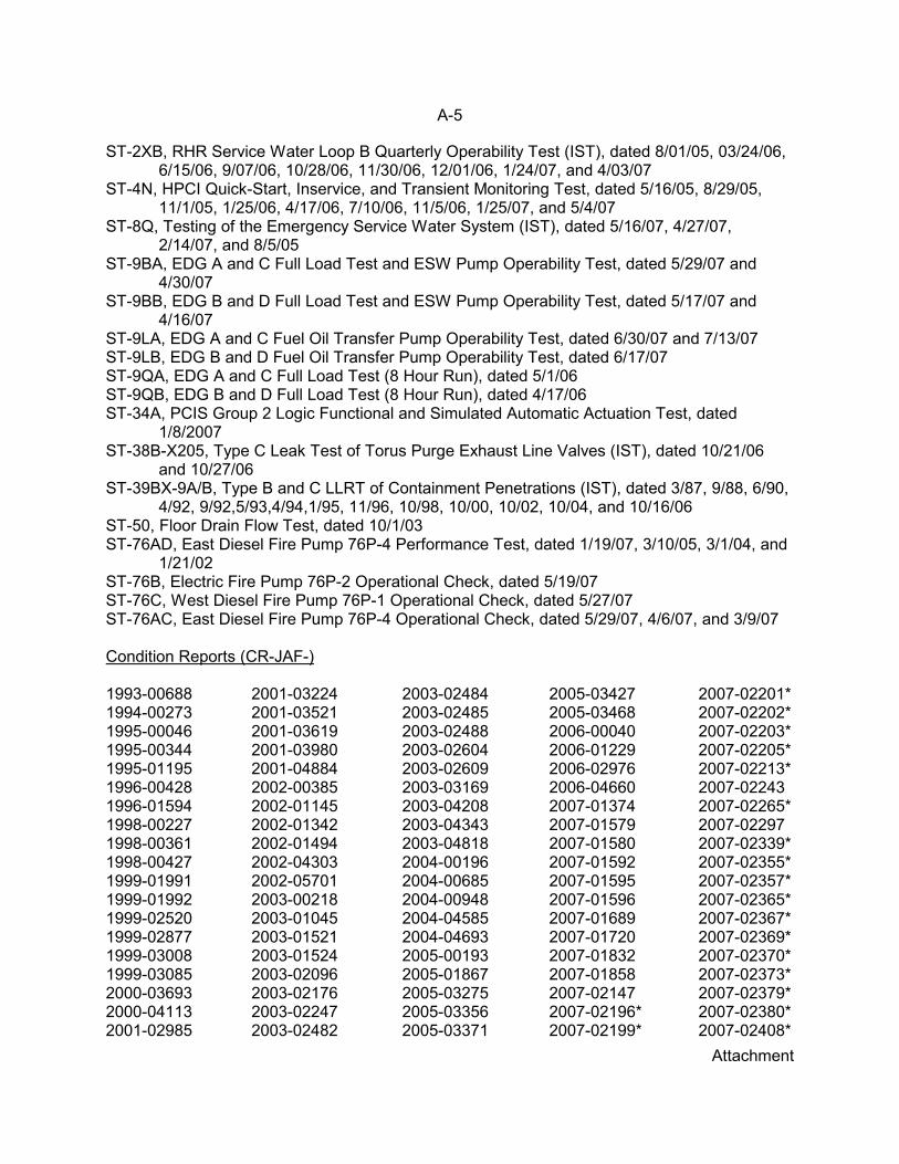
ST-2XB, RHR Service Water Loop B Quarterly Operability Test (IST), dated 8/01/05, 03/24/06,6/15/06, 9/07/06, 10/28/06, 11/30/06, 12/01/06, 1/24/07, and 4/03/07
ST-4N, HPCI Quick-Start, Inservice, and Transient Monitoring Test, dated 5/16/05, 8/29/05,11/1/05, 1/25/06, 4/17/06, 7/10/06, 11/5/06, 1/25/07, and 5/4/07
ST-8Q, Testing of the Emergency Service Water System (IST), dated 5/16/07, 4/27/07,2/14/07, and 8/5/05
ST-9BA, EDG A and C Full Load Test and ESW Pump Operability Test, dated 5/29/07 and4/30/07
ST-9BB, EDG B and D Full Load Test and ESW Pump Operability Test, dated 5/17/07 and4/16/07
ST-9LA, EDG A and C Fuel Oil Transfer Pump Operability Test, dated 6/30/07 and 7/13/07ST-9LB, EDG B and D Fuel Oil Transfer Pump Operability Test, dated 6/17/07 ST-9QA, EDG A and C Full Load Test (8 Hour Run), dated 5/1/06 ST-9QB, EDG B and D Full Load Test (8 Hour Run), dated 4/17/06ST-34A, PCIS Group 2 Logic Functional and Simulated Automatic Actuation Test, dated
1/8/2007ST-38B-X205, Type C Leak Test of Torus Purge Exhaust Line Valves (IST), dated 10/21/06
and 10/27/06ST-39BX-9A/B, Type B and C LLRT of Containment Penetrations (IST), dated 3/87, 9/88, 6/90,
4/92, 9/92,5/93,4/94,1/95, 11/96, 10/98, 10/00, 10/02, 10/04, and 10/16/06ST-50, Floor Drain Flow Test, dated 10/1/03 ST-76AD, East Diesel Fire Pump 76P-4 Performance Test, dated 1/19/07, 3/10/05, 3/1/04, and
1/21/02ST-76B, Electric Fire Pump 76P-2 Operational Check, dated 5/19/07ST-76C, West Diesel Fire Pump 76P-1 Operational Check, dated 5/27/07ST-76AC, East Diesel Fire Pump 76P-4 Operational Check, dated 5/29/07, 4/6/07, and 3/9/07
Condition Reports (CR-JAF-)
1993-006881994-002731995-000461995-003441995-011951996-004281996-015941998-002271998-003611998-004271999-019911999-019921999-025201999-028771999-030081999-030852000-036932000-041132001-02985
2001-032242001-035212001-036192001-039802001-048842002-003852002-011452002-013422002-014942002-043032002-057012003-002182003-010452003-015212003-015242003-020962003-021762003-022472003-02482
2003-024842003-024852003-024882003-026042003-026092003-031692003-042082003-043432003-048182004-001962004-006852004-009482004-045852004-046932005-001932005-018672005-032752005-033562005-03371
2005-034272005-034682006-000402006-012292006-029762006-046602007-013742007-015792007-015802007-015922007-015952007-015962007-016892007-017202007-018322007-018582007-021472007-02196*2007-02199*
2007-02201*2007-02202*2007-02203*2007-02205*2007-02213*2007-022432007-02265*2007-022972007-02339*2007-02355*2007-02357*2007-02365*2007-02367*2007-02369*2007-02370*2007-02373*2007-02379*2007-02380*2007-02408*

A-6
Attachment
2007-02415*2007-02486*2007-02487*2007-02488*
2007-02490*2007-02491*2007-02503*2007-02506*
2007-02519*2007-02528*2007-02538*2007-02540*
2007-02550*2007-02552*2007-02569*
2007-02575*2007-02586*
JAFLO- 2007-00154*
* NRC identified during this inspection
Design and Licensing Bases
DBD-010, Residual Heat Removal System, Rev. 5DBD-16A, Primary Containment Penetrations and Isolation Devices System, Rev. 4DBD-023, High Pressure Safety Injection System, Rev. 11DBD-027, Air Treatment Systems, Rev. 5DBD-046, Normal Service Water - Emergency Service Water - RHR Service Water, Rev. 17DBD-071, Electrical Distribution Systems 4160V and 600V AC Power Systems, Rev. 3 DBD-092, EDG Building Heating and Ventilation System, Rev. 6DBD-093, Emergency Diesel Generator (EDG), Rev. 11James A. FitzPatrick Updated Final Safety Analysis ReportJPN-91-065, NYPA Letter: Hardened Wetwell Vent Capability for the James A. FitzPatrick
Nuclear Power Plant, dated 12/6/91JPN-92-045, NYPA Letter: Hardened Wetwell Vent Capability, dated 8/14/92 JPN-97-011, 180 Day Response to Generic Letter 96-05: Periodic Verification of Design-Basis
Capability of Safety-Related Motor-Operated Valves, dated 3/17/97NRC Letter to Entergy Nuclear Operations, James A. FitzPatrick Nuclear Power Plant -
Issuance of Amendment RE: Technical Specifications on DC Electrical SystemRequirements (TAC No. MC7204), dated 9/18/06
NRC Letter: Hardened Wetwell Vent Capability at the James A. FitzPatrick Nuclear PowerPlant, dated 9/28/92
NRC Letter to Power Authority of the State of New York, Issuance of Amendment for James A.FitzPatrick Nuclear Power Plant (TAC No. M92781), dated 12/6/96
Drawings
1DF-330, Elementary Diagram 125 V Battery Charger, Rev. 61DF-330W, Battery Charger Wiring Diagram 125 V DC, Rev. 61.14-27 Outline (Induction Motor) Rev. 416.23-27, Process Diagram-HPCI, Rev. 72.13-6, HPCI Pump Curve Head Vs. GPM @2000 RPM, Rev. 32.13-8, HPCI Pump Curve Head Vs. RPM @4250 GPM, Rev. 46H-554645-1, Battery Charger Terminal Panel Detail, Rev. 5187B8307 Sh. 3, Layout BMCC-3, Rev. H187B8307 Sh. 5, Elementary Diagram - FVR 1 and 2, Rev. G187B8307 Sh. 10, Connection Diagram - FVR 1 and 2, Rev. G791E461 Sh. 6, Elementary Diagram RHR System, Rev. H791E465 Sh. 2, Elementary Diagram Core Spray System, Rev. R

A-7
Attachment
791E465 Sh. 3, Elementary Diagram Core Spray System, Rev. K791E465 Sh. 4, Elementary Diagram Core Spray System, Rev. L791E465 Sh. 1, Elementary Diagram Core Spray System, Rev. N865E365 Sh. 5, Elementary Diagram Analog Trip System ATTS, Rev. K11825-1.14-14A, Speed Torque Current Curves Emergency Service Water Pump Motors, dated
12/12/70 11825-FB-9L, Reactor Bldg. Secondary Cont. Air Cooling-Heating and Purging Plan, Rev. 811825-FB-9N-11 Sh. 2, Reactor Bldg. Secondary Cont Air Cooling-Heating and Purging
Sections, Rev. 1111825-FE-IH Sh. 4, 4160 V One Line Diagram Emergency Bus 10500, Rev. 1311825-FM-20D, Flow Diagram - Residual Heat Removal - System No. 10 SH. 4, Rev. 2111825-LP-02-3J, Loop Diagram NBI Reactor Pressure, RHR Core Spray, Recirc Permissive
Low Pressure 02-3PT-52A, Rev. 1A384-X225A Sh. 1, RHR Suction Strainer, Rev. 6ESK-5AB, DC Elementary Diagram - 4160 CKT 4 KV Bus 10300 Reserve Supply ACB, Rev. 24ESK-11AT Sh.1, Elementary Diagram - 125 VDC CKTS Diesel Generator EDG A, Rev. 24ESK-11BB Sh.2, Elementary Diagram - Emergency Diesel Generator EDG A, Rev. 14ESK-11BC Sh.3, Elementary Diagram - Emergency Diesel Generator EDG A, Rev. 22ESK-5BB, DC Elementary Diagram - 4160V CKT Emergency Diesel Generator 93 EDG A
Output ACB, Rev. 27FB-9E, Reactor Bldg. Secondary Cont. Air Cooling-Heating and Purging Plan, Rev. 14FB-9F, Reactor Bldg. Secondary Cont. Air Cooling-Heating and Purging Plan, Rev. 19FB-9G, Reactor Bldg. Secondary Cont. Air Cooling-Heating and Purging Plan, Rev. 11FB-9H, Reactor Bldg. Secondary Cont. Air Cooling-Heating and Purging Plan, Rev. 17FB-9J, Reactor Bldg. Secondary Cont. Air Cooling-Heating and Purging Plan, Rev. 16FB-10H, Flow Diagram, Reactor Building Service Water Cooling Water System 66, Rev. 43FB-16C, Flow Diagram, Emergency Generator Building Ventilation and Heating, System 92,
Rev. 9 FB-30A Sh. 1, Administration Building Plumbing and Fire Protection, Rev. 22FB-30B Sh. 2, Administration Building Plumbing and Fire Protection, Rev. 16FB-36A, Emergency Generator Building-Building Services, Rev. 13FB-49A, Flow Diagram, Fire Protection Water Piping - System 76, Rev. 40FE-1A, Main Online Diagram Generator and Main Transformer, Rev. 20FE-1AH Sh. 1,125 VDC One Line Diagram, Rev. 26FE-1AN Sh. 6,125 VDC One Line Diagram, Rev. 18FE-1AJ Sh. 2, 125 VDC One Line Diagram, Rev. 20FE-1B Sh. 2, Main Online Diagram Station Service Transformers, Rev. 12FE-1C Sh. 3, Main Online Diagram 345 kV Switchyard, Rev. 14FE-1H Sh. 4, 4160 V One line Diagram Emergency Bus 10500, Rev. 13FE-1L Sh. 2, 600V One Line Diagram SWGR 71L15 & 71L16, and 71MCC-153 & 71MCC-163,
Rev. 33FE-1J Sh. 5, 4160V One Line Diagram Emergency Bus 10600, Rev. 14FE-1R Sh. 7, 600V One Line Diagram 71MCC-131,141, 252 and 262, Rev. 28FM-15B, Flow Diagram, Reactor Building Cooling Water System 15, Rev. 26FM-18B, Drywell Inerting, Rev. 37FM-20A, Flow Diagram Residual Heat Removal System 10, Rev. 72FM-20B, Flow Diagram Residual Heat Removal System 10, Rev. 63

A-8
Attachment
FM-23A Sh. 14, Flow Diagram - Core Spray, Rev. 49 FM-25A, Flow Diagram High Pressure Coolant Injection System 23, Rev. 70FM-25B, Flow Diagram, HPCI Lube Oil System 23, Rev. 32FM-46A, Flow Diagram, Service Water System 46, Rev. 82FM-46B, Flow Diagram, Emergency Service Water System 46 and 15, Rev.50FM-46C, Flow Diagram, Service Water System 46, Rev. 17FM-47A, Flow Diagram - Nuclear Boiler Vessel Instruments, Rev. 47FM-48A, Fire Protection Water Piping System 76, Rev. 33FV-17A, No. 2 Fuel Oil Storage Tanks 93-TK-6A, 6B, 6C, 6D, Rev. 4FV-IJ Sh. 9, Drywell and Suppression Chamber Penetrations Location and Details, Rev. 13JAF-ECCS-8020-1000, Sure-Flow Suction Strainer General Notes and Parts List, Rev. 3LP-02-3A, Loop Diagram NBI/HPCI, RCIC and ATWS, Initiate Reactor Vessel Level 02-3LT-
72A, Rev. 4LP-05J, Loop Diagram HPCI System Reactor Level 8 Trip 02-3LT-83C, Rev. 1LP-05K, Loop Diagram HPCI System Reactor Level 8 Trip 02-3LT-83D, Rev. 1PFP-PWR31, Emergency Diesel Generator Spaces - South, Rev. 2PFP-PWR32, Emergency Diesel Generator Spaces - North, Rev. 2PFSK-8082, East/West Cable Tunnel Fire Suppression System Pipe Support Details
Civil/Structural, Rev. 1SE-10Z, 125 VDC Wiring Diagram Onstream Shutoff Valve 13MOV-039, Rev. 8
Engineering Change Documents (Modifications)
MOD F1-86-094, Fire Protection Cross-Tie To RHRSWMOD M1-88-238, Fire Protection - Emergency Service Water Cross-Tie to EDGMOD D1-90-120, Replacement of Existing HPCI Turbine Oil Filters with New Filters Having a
10 Micron Mesh MOD F1-97-016, Raise Maximum Allowable Lake Temperature From 82°F to 85°F
Engineering Evaluations
043082, James A. FitzPatrick Nuclear Power Plant - Voltage Limit Study, dated 12/6/1976IST-02-03, Exclusion of EDG Support Systems From IST Testing, dated 2/19/02JAF-04-15054, Evaluate and Recommend Guidance for Venting of Level Switch, Rev. 0JAF-RPT-SWS-04335, The Effect of the Keep-Full Check Valves 46ESW-40A(B) Failure to
Close on Reverse Flow on the Potential for Water Hammer in the ESW System, Rev. 0JAF-SE-90-067, Clarification of Design Basis Requirements for the JAFNPP Emergency
Service Water System, Rev. 5JAF-SE-96-048, Revision to FSAR to Raise Maximum Allowable Lake Temperature From 82°F
to 85°F, Rev. 2J.O. 14620.9015 PAS-27816, Evaluation of Impact of Flooding Inside Emergency Diesel
Generator Rooms on Safety Related Equipment James A. FitzPatrick Nuclear PowerPlant, dated 4/19/89
J.O. 14620.9017 PAS-27876, EDG Room Floor Drainage Requirement Evaluation James A.FitzPatrick Nuclear Power Plant, dated 6/9/89
OER No. P067, Potential Damage to Redundant Safety Equipment Via Floor Drain System,dated 9/11/84

A-9
Attachment
Maintenance Work Orders
0100621011618403007280300899030524103056600327872
0327873032787403278760331410038061004170870426872
0436895043979605157300523782052472505359790627607
0627614062796606292330713413860214587051019200235
920472992099899298129940063694090279703328
Miscellaneous
C.A. Stool, GE Nuclear Energy, letter to Richard Chi, New York Power Authority, JA FitzPatrick(JAFNPP) Power Uprate Program – Assessment of Impact on HPCI and RCIC Systems,December 21, 1990
Certificate of Conformance, EDG Heat Exchangers S/Ns 13299 and 13300, dated 9/25/98EPRI Pipe Rupture Frequencies for Internal Flooding PRAs, Rev. 1EPRI TR-105396, PSA Applications Guide, August 1995 JAF-06-29233 (RP 18), 27AOV-117(OP) Operator Work Around to Repair Manual OperatorJAF LER 87-10, HPCI Inoperable Due to Auxiliary Oil Pump Low Pressure, dated 8/21/87JD-03-005, Keep Full Level Switch Replacement, Rev. 0JENG-05-0059, JAF Expert Panel Meeting Minutes - February 15-16, 2005, dated 3/8/05JMD-89-097, Meeting to Discuss Fuel Levels for EDG Storage Tanks (93TK-6A, B, C, D), dated
8/31/89JSEM 90-0033, Results of EDG Fuel Consumption Test (TST-7), dated 6/18/90Limitorque Maintenance Update 90-01Memo from L. Leiter, Discussion of EDG Frequency Variation of 2% on Pump IST, dated
7/13/07MPR-2093, Predicting Capability and Stroke Time in DC Motor-Operated Valves, Rev. 2NEI 9104, Severe Accident Issue Closure Guidelines, Rev. 1NRC VIO 50-271/99-04, Modification for hardened Vent Did Not Consider Containment
FloodingTop Ten Issue Resolution Plan for RHR/ESW/Normal Service Water Strainers, dated 3/24/07TST-007, EDG Fuel Consumption Test, dated 4/11/90Work History for 23P-150 (HPCI AOP), 76P-4 (diesel driven fire pump), and 46P-2A (A ESW
pump)
Normal and Special (Abnormal) Operations Procedures
AOP-1, Reactor Scram, Rev. 42AOP-39, Loss of Coolant, Rev. 17AOP-49, Station Blackout, Rev. 14AOP-51, Unexpected Fire Pump Start, Rev. 5 AOP-64, Loss of Intake Water Level, Rev. 7EOP-2, RPV Control, Rev. 8 EOP-3, Failure to Scram, Rev. 8 EOP-3a, Failure to Scram - Emergency Depressurization, Rev. 1

A-10
Attachment
EOP-4, Primary Containment Control, Rev. 7EOP-4a, Primary Containment Gas Control, Rev. 6EOP-11, EOP and SOAG Graphs, Rev. 1 EP-1, EOP Entry and Use, Rev. 9EP-5, Terminate and Prevent RPV Injection, Rev. 3EP-6, Post Accident Containment Venting and Gas Control, Rev. 8EP-11, Alternate Depressurization, Rev. 1EP-13, RPV Venting, Rev. 2ODSO-17, Operator Plant Tour and Operating Logs, Rev. 75OP-13, Residual Heat Removal System, Rev. 93OP-15, High Pressure Coolant Injection, Rev. 52OP-21, Emergency Service Water (ESW), Rev. 34OP-22 , Emergency Diesel Generators, Rev. 52 OP-33, Fire Protection, Rev. 48OP-43A, 125 VDC Power System, Rev. 22OP-60, Diesel Generator Room Ventilation, Rev. 7OP-65, Operations Tours - Turbine Building Tour, Rev. 58
Operating Experience
DER-98-00014, OER Evaluation of NRC IE Notice Number 97-90, Use of NonconservativeAcceptance Criteria in Safety Related Pump Surveillance Tests
IE Bulletin No. 80-10: Contamination of Nonradioactive System and Resulting Potential forUnmonitored Uncontrolled Release of Radioactivity to Environment, dated 5/6/80
NRC Information Notice 83-44, Supplement 1: Potential Damage to Redundant SafetyEquipment as a Result of Backflow Through the Equipment and Floor Drain System,dated 8/30/90
NRC Information Notice 97-90: Use of Nonconservative Acceptance Criteria in Safety RelatedPump Surveillance Tests, dated 12/30/97
NRC Information Notice 98-31: Fire Protection System Design Deficiencies and Common-modeFlooding of Emergency Core Cooling System Rooms at Washington Nuclear ProjectUnit 2, dated 8/18/98
NRC Information Notice 2005-04: Single-Failure and Fire Vulnerability of Redundant ElectricalSafety Buses, dated 2/14/05
NRC Information Notice 2005-11: Internal Flooding/spray-down of Safety-related EquipmentDue to Unsealed Equipment Hatch Floor Plugs And/or Blocked Floor Drains, dated5/6/05
NRC Information Notice 2005-30: Safe Shutdown Potentially Challenged By UnanalyzedInternal Flooding Events and Inadequate Design, dated 11/7/05
Operating Experience Report 5514 090, NRCIN 83-44 - Potential Damage to Redundant SafetyEquipment via Floor Drain System, dated 9/11/84
Operator Training
Evaluation Scenario Eval 2006 CJPM 2004246B, Supplying Cooling Water to EDGs B and D from Fire Protection, Rev. 3JPM 2005213, Manual Operation of Vent and Purge Valves, Rev. 4

A-11
Attachment
Scenario 70275-1-L01, Rev. 6Scenario 70890-2, Rev. 2Scenario 71390-4, Rev. 0SDLP 01B, Standby Gas Treatment System, Rev. 12SDLP 02J, ADS, Rev. 12 SDLP 16A, Primary and Secondary Containment System, Rev. 10SDLP 16B, Primary Containment Auxiliary Systems, Rev. 16SDLP 46B, ESW System, Rev. 14
Preventive Maintenance
JAF-06-28033, Calibrate 71-50, 51-A(B,C)-1HOEA02, dated 10/24/06JAF-04-31991, Calibration of 71AM-560-21, 71AM-560-22 and 71AM-560-23, dated 10/21/05JAF-00-06498, Sample Upper and Lower Motor Bearing Oil Reservoir, dated 10/27/00JAF-05-24725, Calibration of 71AM-560-21, dated 10/24/05
Procedures
EN-DCC-331, MOV Program, Rev. 0IMP -71.23, Station Battery Charger 71BC-1A(1B) Undervoltage and Ground Alarms, Rev. 11MDSO-02, Fastener Preload Requirements, Rev. 13MP-093.11, EDG System Mechanical PM, Rev. 24SP-01.07, Diesel Fuel Oil Sampling and Analysis, Rev. 10ST-2BA, RHRSW Loop A Crosstie Drain Solenoid Valve Test, Rev. 0ST-2AL, RHR Loop A Quarterly Operability Test (IST), Rev. 24ST-9BA, EDG A and C Full Load Test and ESW Pump Operability Test, Rev.8ST-40K, Periodic Tests and Inspections, Rev. 26ST-50, Floor Drain Flow Test, Rev. 5
Risk and Margin Management
JAF Margin Issues Report, dated 5/15/07JAF-RPT-MULTI-02107, James A. FitzPatrick Nuclear Power Station IPE Update, Revs. 2 & 3JAF-RPT-MULTI-02107, James A. FitzPatrick Nuclear Power Station IPEEE Update, Rev. 2Post Accident Human Reliability Analysis, Rev. 2Risk-Informed Inspection Notebook for James A. FitzPatrick Nuclear Power Plant, Rev. 2.1
System Health Reports and Trending
02-ADS Automatic Depressurization System, 1st Quarter 2007010-Residual Heat Removal System, 1st Quarter 2007013-RCIC System, 1st Quarter 2007014-Core Spray, 1st Quarter 2007023-HPCI System, 1st Quarter 2007027-Containment Atmosphere Dilution (CAD), 1st Quarter 2007039-Instrument/Breathing/Service Air, 1st Quarter 2007046-Emergency Service Water, 1st Quarter 2007

A-12
Attachment
071-AC 4KV System, 1st Quarter 2007071-AC 600V and Under Systems, 1st Quarter 2007071-DC Electrical Distribution System, 1st Quarter 2007076-Fire Protection, 1st Quarter 2007092-EDG Ventilation, 1st Quarter 2007093- Emergency Diesel Generator System, 1st Quarter 2007GL 96-05 Component Monitoring Report, dated 6/12/07JAF Top Ten Equipment Reliability Issues Database Summary, dated 6/11/07PD04775, Record of Eddy Current Inspection of EDG A Jacket Water Cooler, December 2005P.O. No. 10153706 Lab No. 525640, Certificate of Analysis (A EDG Fuel Oil), dated 5/11/07P.O. No. 10153706 Lab No. 525694, Certificate of Analysis (B EDG Fuel Oil), dated 5/25/07
Vendor Technical Manuals
Air Balance Inc., Seismic Certification of Conformance for Models N39AV and N39AH CurtainFire Dampers
JAF-SPEC-SWS-04013, Induction Motor Data Sheet, Rev. 0 Byron Jackson Co. Vendor Drawing No. 11825-2.13-6A, Pump Performance Curve for HPCI
PumpByron Jackson Co. Vendor Drawing No. 11825-2.13-8A, Pump Performance Curve for HPCI
PumpFire Pump Curve, Johnston Pump Co., Pump S/N IQTY-4203, File Number 10.00-144, Rev. CGE EGT: 97-011, HPCI and RCIC Turbine Steam Flow Rates at Re-rated Power for JAFNPP-
Final, dated 3/6/97GE High Pressure Coolant Injection Pump (HPCI) Data Sheet, 21A1068AMGE High Pressure Coolant Injection System Design Specification Data Sheet, 22A4313AAGE High Pressure Coolant Injection System Process Diagram, 729E720BC, Rev. 2GE-NE-187-46-1191, JAF Power Uprate Phase II, Assessment of Impact on HPCI and RCIC
Systems, November 1991GE NEDC-32016P-1, Power Uprate Safety Analysis for the James A. FitzPatrick Nuclear Power
Plant, April 1993GENE-T23-00766-00-01, Class 3, JAF Containment Analysis, October 1999GE Service Information Letter (SIL) Number 336, Surveillance Requirements for HPCI and
RCIC Systems, Rev. 1GE Turbine Steam Auxiliary Drive Purchase Specification, 21A1079, Rev. 2P319-0047, Power Conversion Products Inc, Installation Procedure for the 120 Volt PC Board,
dated 8/4/89T147-0093(T16), HPCI Turbine Vendor Manual, Rev. 13Vendor Drawing 2.29-8, Characteristic Curve for Item 46P-2A, ESW Pump
LIST OF ACRONYMS
AC Alternating CurrentADAMS Agency-Wide Documents Access and Management SystemAOP Auxiliary Oil PumpAOV Air Operated Valve

A-13
Attachment
ASME American Society of Mechanical EngineersCAP Corrective Action Program CR Condition Report CS Core SprayCST Condensate Storage TankDBD Design Basis Document DC Direct CurrentDRS Division of Reactor Safety ECCS Emergency Core Cooling SystemEDG Emergency Diesel GeneratorEOP Emergency Operating ProcedureEPRI Electric Power Research InstituteESW Emergency Service Water FOST Fuel Oil Storage TankFOTP Fuel Oil Transfer Pump GE General ElectricGL Generic Letter HPCI High Pressure Coolant InjectionIMC Inspection Manual ChapterIN Information NoticeIPEEE Individual Plant Examination of External Events ISFSI Independent Spent Fuel Storage InstallationIST Inservice TestJAF James A. FitzPatrick Nuclear Power PlantJAFLO James A. FitzPatrick Learning Organization (process improvement tool)JPM Job Performance MeasureJW Jacket Water KV KilovoltLER Licensee Event ReportLOCA Loss of Coolant AccidentLPCI Low Pressure Coolant InjectionMCC Motor Control CenterMOV Motor Operated ValveMR Maintenance RuleNCV Non-Cited ViolationNEMA National Electrical Manufacturers AssociationNPSH Net Positive Suction HeadNRC Nuclear Regulatory CommissionNRR Office of Nuclear Reactor RegulationOE Operating ExperienceOpESS Operating Experience Smart SamplePARS Publicly Available RecordsPI&R Problem Identification and Resolution PRA Probabilistic Risk Assessment RAW Risk Achievement WorthRHR Residual Heat RemovalRIS Regulatory Issue Summary

A-14
Attachment
RPS Reactor Protection SystemRRW Risk Reduction WorthSAT Systematic Approach to TrainingSBO Station Blackout SDP Significance Determination ProcessSLC Standby Liquid Control SPAR Standardized Plant Analysis Risk SR Surveillance Requirement SRV Safety Relief ValveSSC Structure, System, and ComponentST Surveillance Test TS Technical SpecificationUFSAR Updated Final Safety Analysis ReportUV UndervoltageV VoltVac Volts Alternating CurrentVdc Volts Direct Current

![005014899 00138€¦ · 252 WILLS AND FITZPATRICK Catherine. Effects £485. FITZPATRICK Daniel. £79 15B. ti561 FITZPATRICK Edward. Effects £318 IOS. 118] FITZPATRICK Jane,](https://img.pdfslide.us/doc/110x75/6059be5bdbe04d125f77fe02/005014899-252-wills-and-fitzpatrick-catherine-effects-485-fitzpatrick-daniel.jpg)


![Silence [becca fitzpatrick]](https://img.pdfslide.us/doc/110x75/5559bd13d8b42aaa6f8b4ca5/silence-becca-fitzpatrick-55849e329a513.jpg)


![Dermatologia - Fitzpatrick[1]](https://img.pdfslide.us/doc/110x75/55cf9903550346d0339b01b7/dermatologia-fitzpatrick1.jpg)