Embed Size (px)
Citation preview

INDUSTRIAL HEAD INJURIES AND THE PERFORMANCE OF HELMETS
A. Hulme, N. J. Mills & A. Gilchrist School of Metallurgy and Materials, University of Birmingham, B 1 5 2TI, UK
ABSTRACT The types of head and neck injuries in industrial accidents are reviewed, and the causes classified. lt is found that concussion rather than neck fracture is the most common injury, yet the test criterion in the European standard appears to be for neck fracture. A modified car-crash dummy with a flexible neck was used to evaluate the linear and rotational accelerations in typical industrial accidents. Oblique impacts are the most frequent, and these can cause high angular rotations of the head. Helmets containing foam liners provide better protection against skull fractures than the traditional industrial hard-hat with a suspension cradle. The connection between the kinetic energies of survivable accidents and the 50 J energy in the European standard is investigated.
LEGISLA TION EXISTS FOR the compulsory wearing of industrial helmets on building sites in the UK[ Health and Safety Executive, 1992] . The British Standard for industrial helmets BS 5240 [ 1987] has two grades of helmet, of which grade 2 has comfort improvements (removable washable sweatbands, and textile webbing cradles). The EEC directive on Personal Protective Equipment, via \Vorking Group 2 of CEN Technical Committee 158, lead to the European Standard for industrial helmets EN 397[1995] in March 1995. The basis for EN 397 appears to be International Standard ISO 3873(1977]. Although the separate national Standards did not differ much, EN 397 is effectively the lowest common denominator of them. For instance the comfort improvements are optional extras, rather than a part of the main standard. However more advanced standards exist in Canada[Canadian Standards Association, 1992] an.d in draft form in the USA[American National Standards, 1992]. This paper investigates the biomechanics basis for the impact tests in the standards, and assesses the accelerations and neck forces in industrial accidents.
RISKS IN THE WORKPLACE
The risks facing industrial workers need to be assessed before a rational design of protective headwear can be made. The distribution of impact sites on the head must be found, together with the kinetic energy, shape and rigidity of the objects that hit the head, or are hit by the head. Some head injuries are received after a fall, so the statistics of the fall distances and the surf aces hit are needed.
In BS 5240 and EN 397 the only impact test is with a 5 kg rigid hemisphere of radius 50 mm falling vertically onto the crown of the helmet(fig. l a). The 50 J impact in BS 5240 is equivalent to a 4. 1 kg (9 lb) house building brick, falling through 1.2 m. This level of energy is easily exceeded in industrial accidents. Impact energies vary enormously; workers have survived impacts to the head of objects with kinetic energies much higher than 100 J. One aim of this paper is to relate the protective capacity of helmets in real accidents to the 50 J level of the standards. lt is not feasible to protect helmet wearers for the most extreme impacts or falls, rather the design should protect the wearer from injury in the majority of accidents.
Surveys showed[Proctor & Rowland, 1986] that objects falling onto the crown of the helmet only accounted for about 30% of impacts (Table 1). There is evidently a need for protection at the front, sides and back of helmets. There is hardly any information on the shape and kinetic energy of the objects that hit the (helmeted) heads of industrial workers.
- 217 -

Table 1 Frequenc of im act sites on the head in industrial accidents(%) Coun left to ri ht back front UK 2 28 7 20 USA 8 26 8 13 46 Canada 10 33 15 7 12
There are many ways an industrial worker can receive an impact to the head. U.S. statistics, given in table 2, analyse the causes [Dept. of Labor, 1980].
T bl 2 C a e ategonsat10n o f f . d ·a1 h d . . . causes o m ustn ea m1unes How accident occurred no hard hat wore hard hat
no % no % head struck non-moving object 278 32 21 12 swinging object struck head 154 1 8 44 26 falling object struck head 309 36 62 36 flying object struck head 86 10 34 20 other cause 36 4 9 5 total 863 100 170 lUU
For the 1023 accidents the proportion of head positions at the time of the accident was:-
Looking straight down looking partially down Looking ahead looking partially up Looking straight up Do not remember
19% of 1023 accidents 36% 28% 13% 2% 3%
The scenario of the industrial helmet standard is uncommon. A falling object hit the head in only 36% of cases, and among these the proportion of 'bulls-eyes' on the crown must be low. As only 28% of the workers were looking ahead at the time the impact, the impact directions relative to the head are varied. This means that the area of protection should be the same as for other types of protective helmet, covering the cranium.
BIOMECHANICS OF HEAD INJURIES
Logically the main injury mechanisms should be identified then injury criteria used to set performance criteria in the helmet standards. Tue mechanisms are:-(a) Skull fractures, due to a concentrated impact force on a small region of the skull.
This can also cause localised injuries to the underlying brain (b) Closed-head injuries in which the linear or angular acceleration of the
brain is such as to cause permanent brain damage. (c) Neck injuries, due to compression or excessive bending of the neck lt is possible for more than one of these to occur simultaneously(fig 1 b ). Statistics of the Dept. of Labor[1980] are given in table 3
Table 3 Numbers of in"uries in a sam le of 1033 cases m no hard hat wore hard hat concussion 2 1 1 50 skull fracture 22 7 neck or spine fracture 0 2 neck s rain 64 35
The frequency of neck fracture is so low, compared with concussion or skull fractures, that the protection criteria for the industrial helmets should be changed to reflect this. The Workers Compensation Board of Ontario keeps information on numbers of concussions, skull fractures
- 21 8 -
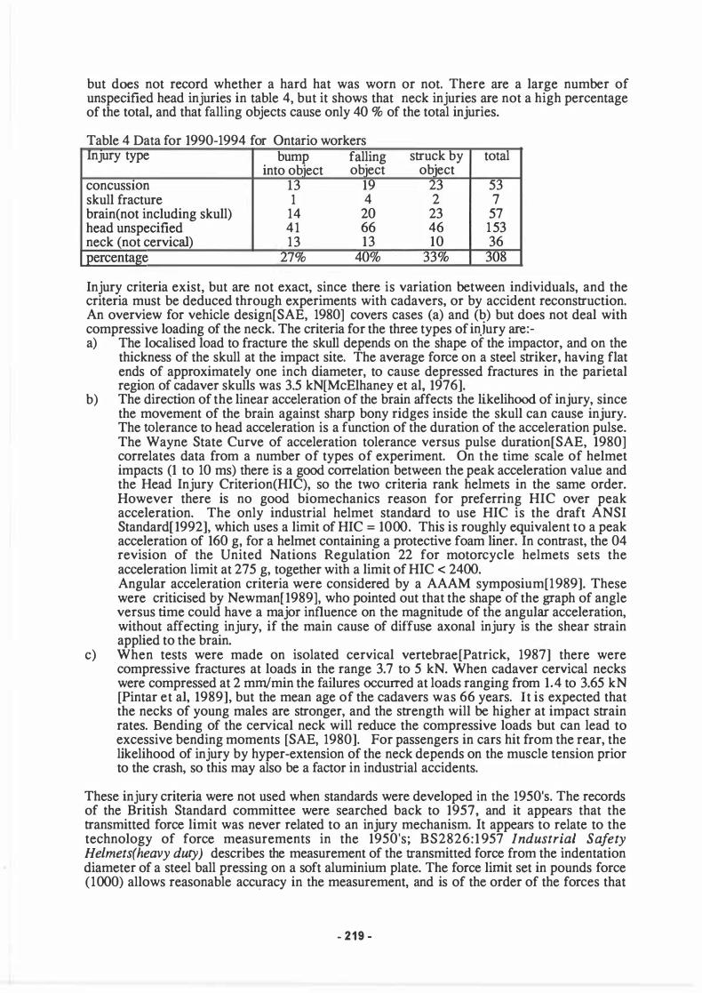
but does not record whether a hard hat was worn or not. There are a large number of unspecified head injuries in table 4, but it shows that neck injuries are not a high percentage of the total, and that falling objects cause only 40 % of the total injuries.
Table 4 Data for 1990-1994 for Ontario workers Injury type bump falling
concuss10n skull fracture brain(not including skull) head unspecified neck (not cervical)
into ob'ect ob'ect 13 19 1 4
14 20 41 66 13 13 7%
struck by total ob'ect
2 5 2 7
23 57 46 1 53 10 36
Injury criteria exist, but are not exact, since there is variation between individuals, and the criteria must be deduced through experiments with cadavers, or by accident reconstruction. An overview for vehicle design[SAE, 1980] covers cases (a) and (b) but does not deal with compressive loading of the neck. The criteria for the three types of injury are:-a) The localised load to fracture the skull depends on the shape of the impactor, and on the
thickness of the skull at the impact site. The average force on a steel striker, having flat ends of approximately one inch diameter, to cause depressed fractures in the parietal region of cadaver skulls was 3.5 kN[McElhaney et al, 1976].
b) The direction of the linear acceleration of the brain affects the likelihood of injury, since the movement of the brain against sharp bony ridges inside the skull can cause injury. The tolerance to head acceleration is a function of the duration of the acceleration pulse. The Wayne State Curve of acceleration tolerance versus pulse duration[SAE, 1980] correlates data from a number of types of experiment. On the time scale of helmet impacts (1 to 10 ms) there is a good correlation between the peak acceleration value and the Head Injury Criterion(HIC), so the two criteria rank helmets in the same order. However there is no good biomechanics reason for preferring HIC over peak acceleration. The only industrial helmet standard to use HIC is the draft ANSI Standard[1992], which uses a limit of HIC = 1000. This is roughly equivalent to a peak acceleration of 160 g, for a helmet containing a protective foam liner. In contrast, the 04 revision of the United Nations Regulation 22 for motorcycle helmets sets the acceleration limit at 275 g, together with a limit of HIC < 2400. Angular acceleration criteria were considered by a AAAM symposium[1989]. These were criticised by Newman[ 1989], who pointed out that the shape of the graph of angle versus time could have a major influence on the magnitude of the angular acceleration, without affecting injury, if the main cause of diffuse axonal injury is the shear strain applied to the brain.
c) When tests were made on isolated cervical vertebrae[Patrick, 1987] there were compressive fractures at loads in the range 3.7 to 5 kN. When cadaver cervical necks were compressed at 2 mm/min the failures occurred at loads ranging from 1.4 to 3.65 kN [Pintar et al, 1989], but the mean age of the cadavers was 66 years. lt is expected that the necks of young males are stronger, and the strength will be higher at impact strain rates. Bending of the cervical neck will reduce the compressive loads but can lead to excessive bending moments [SAE, 1980]. For passengers in cars hit from the rear, the likelihood of injury by hyper-extension of the neck depends on the muscle tension prior to the crash, so this may also be a factor in industrial accidents.
These injury criteria were not used when standards were developed in the 1950's. The records of the British Standard committee were searched back to 1957, and it appears that the transmitted force limit was never related to an injury mechanism. lt appears to relate to the technology of force measurements in the 1950's; BS2826:1 957 Industrial Safety Helmets(heavy duty) describes the measurement of the transmitted force from the indentation diameter of a steel ball pressing on a soft aluminium plate. The force limit set in pounds force (1000) allows reasonable acc�racy in the measurement, and is of the order of the forces that
- 219 -
cause injury. The helmets were fastened to a fixed headform then a hemispherical striker of 5 kg mass and radius 48 mm dropped vertically onto the crown of the helmet. With metrication the force limit was altered to 5 kN. The Standards do not mention the injury type(s) that the helmets are meant to prevent.
PROTECTION AGAINST SKULL FRACTURE
There is no consideration in the standards of the possibility that a localised force less than 5 kN could cause a skull fracture. There is a penetration test using a conical spike in the standard, that could apply a high localised pressure to the headform. The kinetic energy of the conical striker is 30 J and the impact site is within 50 mm of the crown of the shell. However the frequency of accidents involving spikes is extremely small and the test causes the outer shell of helmets to be excessively thick.
Aldman[1984] proposed the replacement of the penetration test for cycle helmets by an impact with a 25 mm radius hemispherical striker. He stated that a depressed skull fracture would be likely in the temporal area, if the impacted area was less than 500 mm2 and the localised pressure exceeded 4 MPa, implying a localised force exceeding 2 kN. In the proposed test[Williams, 1990] the force, measured with a load cell of surface area 1 10 mm2 imbedded in the headform, must not exceed 2 kN (a pressure of 1 8 MPa) when the helmeted headform falls 700 mm onto a rigid 25 mm radius hemispherical anvil. The impact energy, ignoring the mass of the helmet, is 35 J.
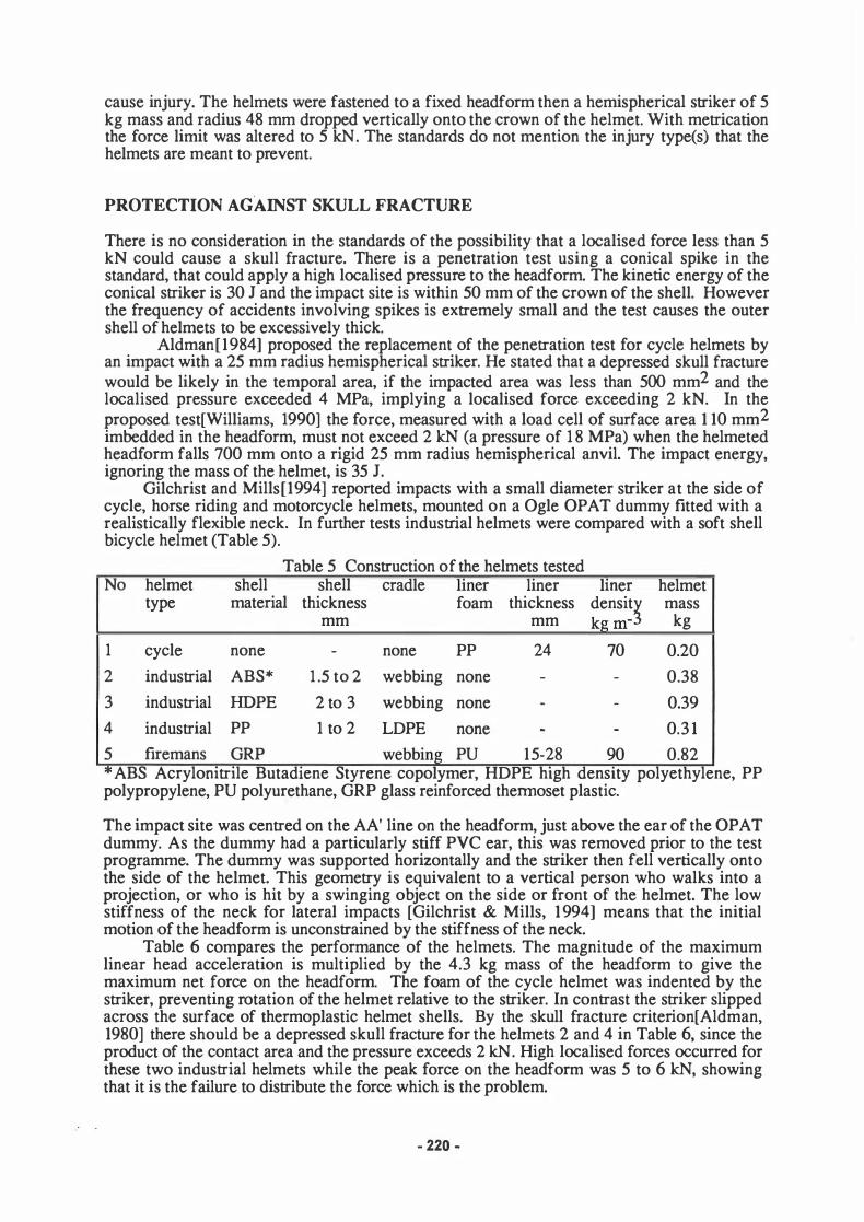
Gilchrist and Mills[1994] reported impacts with a small diameter striker at the side of cycle, horse riding and motorcycle helmets, mounted on a Ogle OPA T dummy fitted with a realistically flexible neck. In further tests industrial helmets were compared with a soft shell bicycle helmet (Table 5).
Table 5 Construction of the helmets tested No helmet shell shell cradle liner liner lmer helmet
type material thickness foam thickness densit� mass mm mm kgm- kg
1 cycle none - none PP 24 70 0.20
2 industrial ABS* 1 .5 to 2 webbing none - - 0.38
3 industrial HDPE 2 to 3 webbing none - - 0.39
4 industrial PP 1 to 2 LDPE none - - 0.3 1
5 firemans GRP webbing PU 15-28 90 0.82 "' ABS Acrylomtrile Butadiene Styrene copolymer, HDPE high density polyethylene, PP polypropylene, PU polyurethane, GRP glass reinforced thermoset plastic.
The impact site was centred on the AA' line on the headform, just above the ear of the OPAT dummy. As the dummy had a particularly stiff PVC ear, this was removed prior to the test programme. The dummy was supported horizontally and the striker then fell vertically onto the side of the helmet. This geometry is equivalent to a vertical person who walks into a projection, or who is hit by a swinging object on the side or front of the helmet. The low stiffness of the neck for lateral impacts [Gilchrist & Mills, 1 994] means that the initial motion of the headform is unconstrained by the stiffness of the neck.
Table 6 compares the performance of the helmets. The magnitude of the maximum linear head acceleration is multiplied by the 4.3 kg mass of the headform to give the maximum net force on the headform. The foam of the cycle helmet was indented by the striker, preventing rotation of the helmet relative to the striker. In contrast the striker slipped across the surface of thermoplastic helmet shells. By the skull fracture criterion[Aldman, 1980] there should be a depressed skull fracture for the helmets 2 and 4 in Table 6, since the product of the contact area and the pressure exceeds 2 kN. High localised forces occurred for these two industrial helmets while the peak force on the headform was 5 to 6 kN, showing that it is the failure to distribute the force which is the problem.
- 220 -

Table 6 Lateral impacts with a 35 mm diameter striker No helmet type Max. head Maximum Maximum Max. contact area Impact
force striker force rot. accel. rotation mm2 energy kN kN 1000 rad s-2 degrees (pressure MPa) J
1 PP foam cycle 2.79 2.82 6.3 46.5 960 (2) 90
2 ABS industrial 6.0 & 3.4 30.2 43 706(4.5) 50
2 " 3 1 . 1 1 89 40 800(5) & 227(>5) 90
3 PE industrial 12.0 & 5.82 7.6 3 1 42 50
4 PP industrial 5.4 8.0 30.2 45 400 & 300(5) 50
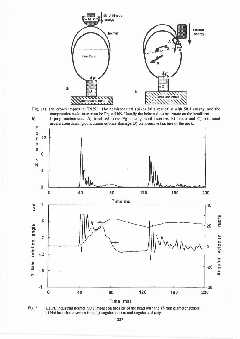
4 " 23. 1 1 00 38.5 490(>5) & 178(>5) 90 In these tests the industrial helmets were knocked off the headform, and the PP shell was detached from the headband. There was noticeable local deformation of the shells of these helmets. High speed film was used during lateral impacts on the IIDPE industrial helmet and a polypropylene foam cycle helmet. The linear acceleration and rotational velocity traces are shown in fig. 2, while table 7 lists the events. After the initial impact the headform accelerates away from the striker, but then slows before the second impact occurs. The striker velocity is 6.4 m s-1 prior to the first impact and 2.7 m s-1 prior to the second impact. The second impact produces a high force for a low striker velocity because the helmet has come off. The helmet provides little protection for the first lateral impact because the thin shell at the sides bends easily and suspension design is very soft for lateral impacts(fig. 6)
Table 7 Events during lateral impacts on helmets.
Event Time ms HDPE indust cycle
Striker contact with helmet shell 0.0 0.0 Head starts to move 3.0 5.9 Striker loses contact with shell 8.9 14.8 Helmet starts to come off 20.7 -
Torso begins to move down 26.7 Second impact on helmet or head 87.7 107
The PP foam in the cycle helmet absorbs much of the impact energy, so there is a delay in the time when the headform is noted to move, and in the time for the helmet to rebound from the striker. The headform experiences a much lower peak angular acceleration than when protected by the industrial helmet, but this may be more a function of the oscillatory nature of the angular velocity response for the industrial helmet(fig 2b ).
HEAD ACCELERATION AND FORCES ON THE NECK
Car crash dummies are not designed for impacts on the top of the head. The Ogle OPA T dummy has a rigid steel spine, so there is no compressive compliance of the lumbar spine, and the effective mass of the torso is too high for a vertical impact on the neck. This means that the axial neck forces measured will be unrealistically large because of the high axial stiffness of the dummy neck and spine. Our flexible neck will buckle more easily when compressed axially than the solid rubber neck supplied with the Ogle dummy, however it is less easy to buckle than a human neck. Pintar et al[l989] compressed cadaver cervical spines axially at 2 mm/min. From their results the axial stiffness of the spine is about 1 50 N/mm, and they showed that the spines buckled.
- 221 -

Fig. 3 shows the head, with both the helmet and the neck being modelled by linear springs. The dynamic vertical stiffness k1 of the suspension cradles of industrial helmets is about 120 N mm-1 using a 50 mm radius hemispherical striker (Mills & Gilchrist, 1993). The spring constant of the neck from Pintar's data is k2 = 150 N mm-1. Tue vertical motion can be modelled as 3 masses linked by 2 springs. For a live person wearing a traditional design of industrial helmet the stiffnesses of the helmet and the neck are comparable, so the dynamics of the motion will be complex. Mills & Gilchrist(1993) used computer models to predict the force time traces.
When the Ogle dummy is fitted with a conventional industrial helmet, its axial neck stiffness k2 is far higher than the helmet suspension stiffness ki, so the impact circumstances are close to those in EN 397, with a fixed headform of effectively infinite mass. Tue finite mass of the dummy torso will mean that it will accelerate downwards. In the experiments with the dummy, the total force on the head can be calculated from the product of the head mass and the magnitude of its linear acceleration. If the compressive force on the neck is significantly !arger than the total force on the head, this shows that the neck is too stiff in the axial direction.
Tests were carried out on the seated dummy wearing HDPE or PP industrial helmets (Table 8). A Kistler quartz load washer of 35kN capacity was mounted below the neck to measure the axial forces. A cast aluminium hemisphere of radius 80 mm and mass 5.45 kg, and a rough surf ace, was used for the impacts. For 100 J energy impacts on the crown of the HDPE helmet, the peak acceleration of the head was 1 33 g, so the net force on the headform was 5.5 kN (fig. 4). Little head rotation occurs but some of the impact energy is absorbed by the cushions under the body of the dummy. In a real accident the knees buckling would have a similar effect. The rotational movement is small as the horizontal component of the force acting on the head is small. The majority of the impact force is transmitted vertically through the neck and spine. Tue helmet came off the head leaving it exposed to further impacts when the dummy then fell over backwards.
Fig. 4 shows that the angular velocity traces are oscillatory in nature. If the angular acceleration is calculated by numerically differentiating these traces the acceleration traces are even more oscillatory. Tue peak rotational accelerations are very high, but are unlikely to correlate with brain injuries. The maximum rotation angle about the coronal axis(tables 6 and 8) ,which occurs within a time interval < 50 ms, should correlate better with diffuse axonal injury.
Table 8 Impact tests on sitting OPAT dummy, with objects falling vertically.
Heimet Test Energy Impact Heimet Max. Max. Rotational Max. Rotation shell Site Retained Force Acceleration Degrees
J kN k rad s-2
HDPE h 100 c no 5.5 35.2 9.3
HDPE h 100 sl no 2.9 7.5 17.8
HDPE h 100 s2 no 1 .6 10.8 39.1
PP h 100 s2 no 1 .6 4.6 30.4
PP s 45 s2 yes 0.9 - 2.5 striker: h - hermsphencal , s - Spanner site: c - crown. s l - 40 mm and s2 - 70 mm to the side of the crown.
For the 100 J off-centre impacts the bending of the neck plays a major role. There is a single impact on the helmet (Fig. 5a), and the peak linear acceleration of the head is much lower than for the crown impact. The striker is deflected laterally from its path by the impact and the large horizontal component of the contact force rotates the head on the neck. The angular velocity of the head is high (Fig. 5b), and the head has a maximum angular deflection
of nearly 40°. Impacts with the end of a large 2 kg spanner produced very small forces even though the impact energy was 45 J.
- 222 -
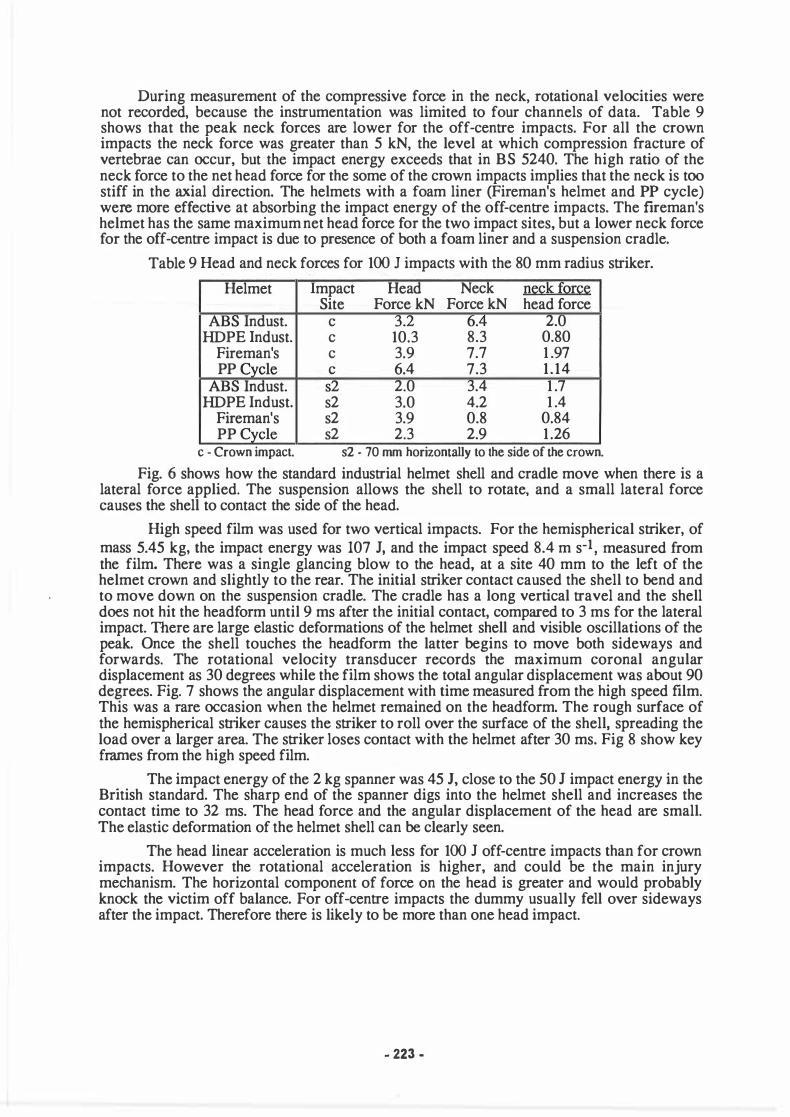
During measurement of the compressive force in the neck, rotational velocities were not recorded, because the instrumentation was limited to four channels of data. Table 9 shows that the peak neck forces are lower for the off-centre impacts. For all the crown impacts the neck force was greater than 5 kN, the level at which compression fracture of vertebrae can occur, but the impact energy exceeds that in BS 5240. The high ratio of the neck force to the net head force for the some of the crown impacts implies that the neck is too stiff in the axial direction. The helmets with a foam liner (Fireman's helmet and PP cycle) were more effective at absorbing the impact energy of the off-centre impacts. The fireman's helmet has the same maximum net head force for the two impact sites, but a lower neck force for the off-centre impact is due to presence of both a foam liner and a suspension cradle.
Table 9 Head and neck forces for 100 J impacts with the 80 mm radius striker.
Helmet Impact He ad Neck n��k fQJ:Q� Site Force kN Force kN head force
ABS Indust. c 3.2 6.4 2.0 HDPE lndust. c 10.3 8.3 0.80
Fireman's c 3.9 7.7 1 .97 PP Cvcle c 6.4 7.3 1 . 14
ABS Indust. s2 2.0 3.4 1 .7 HDPE Indust. s2 3.0 4.2 1 .4
Fireman's s2 3.9 0.8 0.84 PP Cycle s2 2.3 2.9 1 .26
c - Crown impact. s2 - 70 mm horizontally to the side of the crown.
Fig. 6 shows how the standard industrial helmet shell and cradle move when there is a lateral force applied. The suspension allows the shell to rotate, and a small lateral force causes the shell to contact the side of the head.
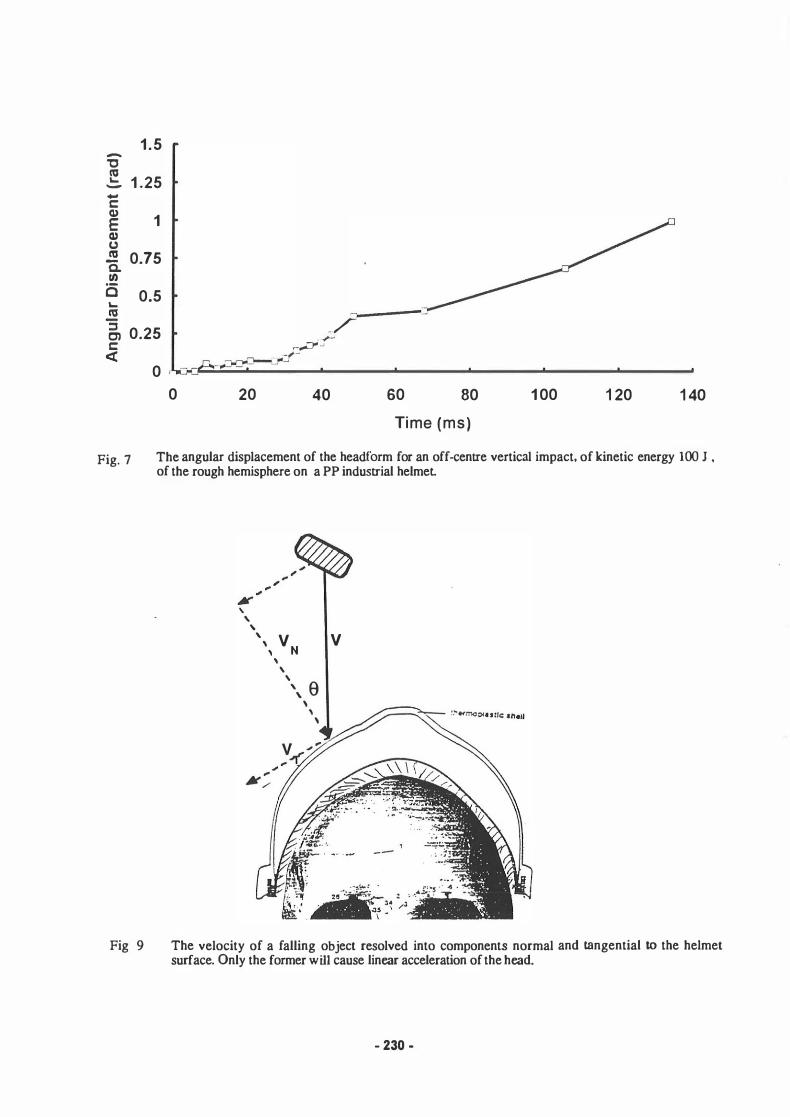
High speed film was used for two vertical impacts. For the hemispherical striker, of mass 5.45 kg, the impact energy was 107 J, and the impact speed 8.4 m s-1 , measured from the film. There was a single glancing blow to the head, at a site 40 mm to the left of the helmet crown and slightly to the rear. The initial striker contact caused the shell to bend and to move down on the suspension cradle. The cradle has a long vertical travel and the shell does not hit the headform until 9 ms after the initial contact, compared to 3 ms for the lateral impact. There are large elastic deformations of the helmet shell and visible oscillations of the peak. Once the shell touches the headform the lauer begins to move both sideways and forwards. The rotational velocity transducer records the maximum coronal angular displacement as 30 degrees while the film shows the total angular displacement was about 90 degrees. Fig. 7 shows the angular displacement with time measured from the high speed film. This was a rare occasion when the helmet remained on the headf orm. The rough surface of the hemispherical striker causes the striker to roll over the surface of the shell, spreading the load over a larger area. The striker loses contact with the helmet after 30 ms. Fig 8 show key frames from the high speed film.
The impact energy of the 2 kg spanner was 45 J, close to the 50 J impact energy in the British standard. The sharp end of the spanner digs into the helmet shell and increases the contact time to 32 ms. The head force and the angular displacement of the head are small. The elastic deformation of the helmet shell can be clearly seen.
The head linear acceleration is much less for 100 J off-centre impacts than for crown impacts. However the rotational acceleration is higher, and could be the main injury mechanism. The horizontal component of force on the head is greater and would probably knock the victim off balance. For off-centre impacts the dummy usually fell over sideways after the impact. Therefore there is likely to be more than one head impact.
- 223 -
FLEXIBLE NECK VERSUS FIXED-HEADFORM IMPACT TESTS
Gilchrist and Mills[ 1994] considered the transfer of momentum from a striker of mass m1 moving at velocity V 1 to an initially stationary head and helmet of mass m2. The head and helmet are free to move, and are not constrained by any neck. They used the concept of the 'effective impact energy' Ee, defined as the energy input to the helmet up until the time when the masses have a common velocity,
(4)
A striker kinetic energy of Ee in a fixed headform test will produce the same helmet deformation as that in the free headform test. The concept must be modified when a neck of finite stiffness supports the headform. If the neck stiffness is much less than the contact stiffness of the helmet, the head initially moves as if unconstrained by the neck. This was clearly the case for the lateral impacts on the helmet, but not the case for the vertical impacts on the crown of the helmet. For the off-centre vertical impacts on the dummy the headform can move relatively easily to the side so the effective impact energy concept is appropriate.
Another factor is the oblique nature of many industrial helmet impacts. The velocity of the striker can be resolved into components normal and tangential to the helmet surface (Fig 9). Only the component acting towards the centre of the head acts to compress the helmet
liner and to cause linear acceleration of the head. lf the angle 0 is large, extremely high kinetic energies of the falling object may produce helmet deformations that are less than in the standards that use off crown impacts. The component of kinetic energy acting towards the
centre of the headform is cos2 0 times the actual kinetic energy. This value is then further reduced by the calculation of the effective (fixed headform) impact energy, when comparisons are to be made with the EN 397 test level.
A further factor is energy losses in the plasticised PVC scalp of the Ogle dummy headform, which do not occur with the wooden headforms of BS 5240. The energy dissipated in the PVC depends on the striker geometry, the helmet design and the impact energy. The human head can cope with impact energies of up to 40 J without any helmet protection if the surface hit is reasonably flat. Hence the 50 J protection in EN 397 is in addition to natural protection against skull fracture.
DISCUSSION
The impact sites of falling(or swinging or flying) objects on industrial helmets tend to be random. There are some circumstances, such as walking into a ceiling projection because the wearer is not used to the extra height of the helmet, that lead to a duster of impact sites. In contract with road accidents, where the vertical component of velocity is partly determined by the cyclist's riding height and there is always a rigid flat target (the road) to hit, industrial impacts are likely to be oblique, with a great range of impact energies. In nearly every industrial accident the head rotates when hit. Even a blow on the crown will cause head rotation when the spine buckles. A high linear acceleration of the head, and a large head rotations can occur while the compressive force on the neck remains less than 5 kN, showing that the neck fracture criterion is not relevant to such impacts. Movement of the impact site over the shell surface will lead to a greater volume of foam being crushed in a helmet with a foam liner, than occurs with a vertical impact with a fixed headform. This, together with the head movement and the oblique nature of most impacts, will mean that the survivable impact energy in real accidents is much !arger than the 50 J in the EN 397 impact tests.
The measurements of angular accelerations on dummy headforms show that the signal has a complex oscillatory form. In side impact modelling [Meaney, 1994] there was no impact between the dummy head and the car structure, so the shape of the rotational velocity versus time traces was a simple sine wave with no high frequency components. Any high frequency components in the angular velocity signal, which will occur when there is a direct blow to the head, will cause the angular acceleration to oscillate with high positive and negative peaks. In
- 224 -

�xperiments to induce concussion by angular motion of the heads of animals, or modelling of the motion of the human brain[Meaney and Thibault, 1990], the angular acceleration versus time graphs have a single peak, so there may be a correlation of this peak value with the maximum shear strain values in the brain. However as Newman[1989] commented, if the acceleration graphs are complex there may be no correlation between the peak acceleration and any brain injury. That appears to be the case for experiments reported here. lt is more likely that the brain injuries would correlate with the magnitude of coronal-axis head rotation that occurs in a short time interval, say less than 50 ms.
Phenomena occur during impacts on a flexible-neck dummy that do not occur in the fixed-head impact tests. lf a vertical impact is off-crown, the impact point can skid across the shell surface, and if it reaches the rain gutter the striker can knock the helmet off. Alternatively the rebound of the suspension system can cause the helmet to come off. A better dummy is needed if it is reproduce all the events and accelerations for impacts on the crown of the head. The axial neck stiffness is too high, and the rigid steel lumbar spine means that the effective mass of the torso is also too high. Although the current neck is good for lateral impacts, it needs to be redesigned for vertical impacts on the crown of the helmet. Dummy tests are too complex to be used for routine testing, but they indicate the complex events that occur in real accidents. lt is then possible to address the phenomena separately, for instance by having a separate impact test and retention system test.
Most industrial helmets afford the best protection for vertical impacts on the crown of the head, which is not the most common type of impact. This is a result of the limited impact tests in BS 5240 and EN 397. Industrial helmets differ in design from other helmet types because of the use of the 5 kN transmitted force test criterion, which is possibly related to the forces to cause compressive fractures in the neck. As compressive failures of cervical vertebrae are very rare, while skull fractures and brain injuries are common, the criteria in the standard should be for the latter. The brain injury criterion should be a peak acceleration of at most 250 g. Helmets should protect all parts of the cranium against at least a 50 J impact energy, in a test where either the anvil or the headf orm was fixed. A 20 mm thickness of suitable foam liner should allow the helmet to cope with impacts of at least 100 J. The helmet must protect against localised forces causing skull fractures. The penetration test should be replaced by an impact with a small diameter hemisphere, and the localised force on the headform measured.
Helmets with higher levels of impact protection at the common impact sites are on sale in C�ada and the USA, and the Canadian standard only allows this type of helmet to be certified. EN 397 is restrictive in its requirements, and forces manufacturers to produce a basic form of head protection. Improved head protection would be more expensive, but the $30 to $50 cost is less than that of work boots and coats. When the costs of industrial head injuries, and the social costs of caring for permanently disabled workers, are taken into account the case for the improvement of the standard is very strong. History has shown that manufacturers are not willing to move ahead of the standards, since they fear that the market for improved designs will be weak while cheaper less-effective helmets are still available.
ACKNOWLEDGEMENTS A.H. thanks the Health and Safety Executive for financial support. Tue views in this paper are those of the authors, and do not necessarily reflect HSE policy.
- 225 -
REFERENCES
Aldman A., 1984, A method for the assessment of the load distributing capacity of protective helmets .... , Chalmers Univ. of Technology, Goteborg. Association for the Advancement of Automotive Medicine, 1989, Head Injury mechanisms: the need for an angular acceleration criterion, AAAM, Des Plaines, Il.,. American National Standards, 1992, Z89. l , Requirements for protective headwear for industrial workers, draft 12. Borshuk, P. Ontario Workers Compensation Board, private communication. British Standards Institution, 1987, Industrial Safety Heimets, BS 5240 Pt 1 . Canadian Standards Association, 1992, CSA-Z94. 1 , Industrial Protective Headwear. Chaumard F. et al, 1986, Relationship between some biomechanical and dimensional charactaristics of the skull and the risk of cerebral injuries, IRCOBI conf, Zurich, , 1 33-152. Comite Europeen de Normalisation, 1995, EN 397, Industrial Safety Heimets. Dept. of Labor(U.S.), 1980, Bureau of Labor Statistics, Report 605, Accidents involving head injuries. Gilchrist A. & Mills, N.J., 1994, IRCOBI, Lyon, Protection of the side of the head, 8 1-94 Hickling E. M., 1985, An Investigation on Construction Sites of Factors Affecting the Acceptability and Wear of Safety Heimets, Inst. for Consumer Ergonomics, Univ. of Technology, Loughborough Health and Safety Executive, 1992, Personal Protective Equipment at Work Regulations, HMSO, London. Hulme A, 1995, Ph. D thesis, University of Birmingham. International Organisation for Standardisation, 1977, Industrial Safety Heimets, ISO 3873. McElhaney J.H., Roberts V.L. & Hilyard J.F., 1976, Handbook of human tolerance, Japan Automobile Research Inst, p 276 Meaney D. F. & Thibault. L.E., 1990, Physical model studies of cortical brain deformation ... , IRCOBI conf. Bron, 215-224 Meaney D. F., Thibault. L.E.& Gennarelli, T.A. 1994, Rotational brain injury tolerance criteria as a function of vehicle crash parameters., IRCOBI conf. Lyon, 51-62. Mills, N.J., and Gilchrist A., 1993, Industrial helmet performance in impacts, Safety Science, 16, 221-238 Newman J. A., 1989, AAAM symposium(see above), Consequences of an angular acceleration criterion on protecting for head protection, 39-41. Patrick, L.M., 1987, Neck injury incidence and protection, 3 1 st Proc. Amer. Assoc. Auto. Med. 409-43 1 . Pintar, F.A. e t al, 1989, Kinematic and anatomical analysis of the human cervical spinal column under axial loading, 33rd Stapp Car crash conf. 191-214 Proctor T. D. and Rowland F. J. , 1986, Development of Standards for Industrial Safety Heimets - The State of the Art, J. Occ. Ace. 10., 29-37 Society of Automotive Engineers, 1980, Human tolerance to impact conditions as related to vehicle design, J885, SAE, Warrendale, PA. Williams M., 1990, Evaluation of the penetration test for bicyclists helmets. Accid. Anal. & Prev. 22, 315-325.
- 226 -
! klnetlc energy
a b
Fig. la) The crown impact in EN397. The hemispherical striker falls vertically with 50 J energy, and the compressive neck force must be FN < 5 kN. Usually the helmet does not rotate on the headfonn.
b) Injury mechanisms. A) localised force Fs causing skull fracture, B) linear and C) rotational acceleration causing concussion or brain damage, D) compressive fracture of the neck.
F 0 r 1 2
c e
k N
„ CO „
.!! C> c CO c 0
-CO -0 „
� >< CU ><
8
4
0
1
.6
.2
„2
·.6
-1
0 40 80 1 20 1 60
Time ms
0 40 80 1 20 1 60
Time (ms)
Fig. 2 HDPE industrial helmet. 90 J impact on the side of the head with the 18 mm diameter striker. a) Net head force versus time, b) angular motion and angular velocity.
- 227 -
200
40
cn -„
20 CU ...
> -0 0 0
a> > ... CU
-20 ::J C> c <(
-40 200

'O ('G ...
Q)
1 6
F 0 r 1 2 c e k N
8
4
0
1
.6
C) c ('G .2 c 0 -('G - ·.2 0 ...
.!! )( ('G
-.6 )(
-1
Fig. 4
0
0
Fig. 3 Modelling of the helmet and neck as suspension springs for the head.
40 80
Time ms
40 80
Time (ms)
1 20 1 60
1 20 1 60
200
40
Cl) --'O
20 ('G ... > -0
0 0 Q) > ... ('G ::J -20 C> c
et
-40 200
107 J impact of 80 mm radius rough hemisphere on the crown of HDPE industrial helmet. a) Net head force versus time, b) angular motion and angular velocity.
- 228 -

2
1 .6 F 0 r 1 .2 c e
.8
k N
.4
0 0 40 80 1 20 1 60 200
Time ms
„ 1 20 ca ...
.6 10
c: .2 0 ;: ca 0 -0 ... -.2 0 ->C ca -10 >C -.6
-1 -20 0 40 80 1 20 1 60 200
Time (ms)
Fig. 5 107 J off-centre impacts with 80 mm radius rough hemisphere on HDPE industrial helmet a) Net head force versus time b) angular motion and angular velocity.
before impact crown impact side impact
Fig 6
helmet moves downwards
cradle stretches and shell helmet moves sideways
cradle easily bends bends at thinner sides and shell bends locally
The defonnation of an industrial helmet when there are a)_ crown, b) lateral impacts.
- 229 -
0 -„ ca ...
> -CJ 0 Cl> > ... ca ::::J C'l c:
c(
1 .5 -'C n:J 1 .25 � -
-c C1> 1 E C1> () n:J 0.75 Q. "' c � 0.5 n:J ::::1 0.25 C) c �
0 0
_/ ·-r' ,..,,,,0-..1
-r-
-::,;:-,.., -----:Y-----� 20 40 60 80
Time (ms)
1 00 1 20 1 40
Fig. 7 The angular displacement of the headform for an off-centre vertical impact, of kinetic energy 100 J •
of the rough hemisphere on a PP industrial helmet
Fig 9
' '
'
\, VN V
' ' '
\ 0 ' '
'
The velocity of a falling object resolved into components normal and tangential to the helmet surface. Only the former will cause linear acceleration of the head.
- 230 -
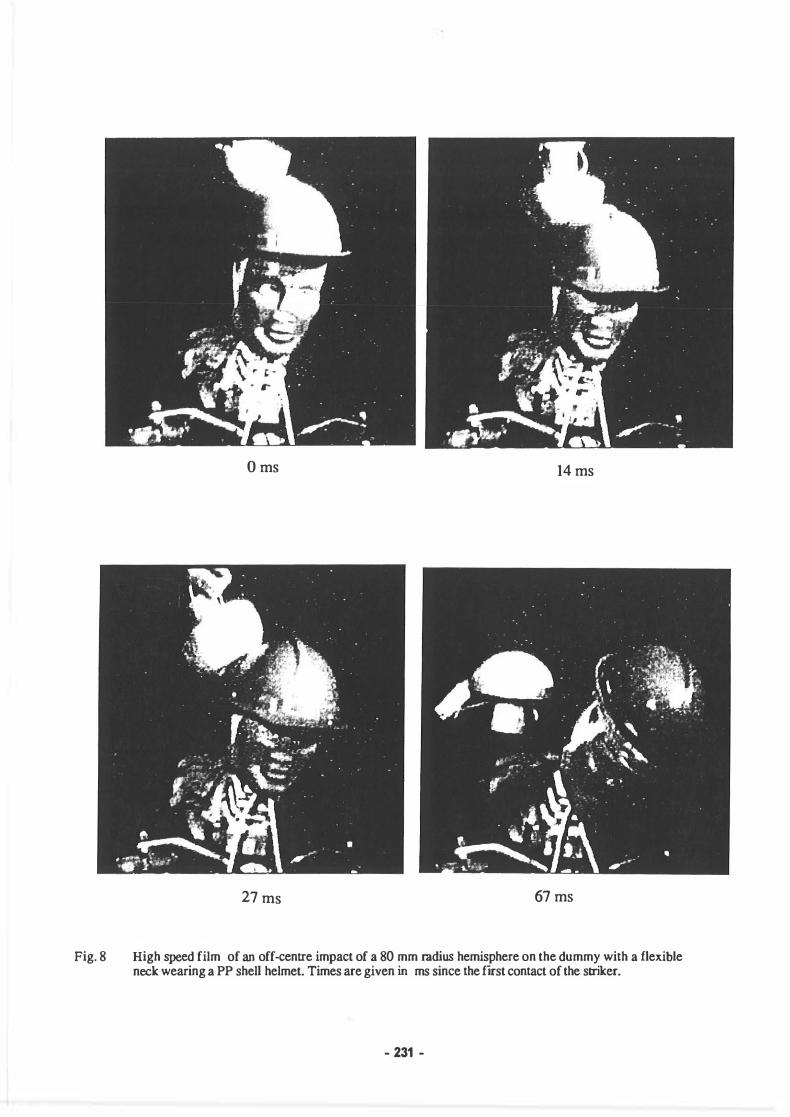
Fig. 8
O ms 14 ms
27 ms 67 ms
High speed film of an off-centre impact of a 80 mm radius hemisphere on the dummy with a flexible neck wearing a PP shell helmet. Times are given in ms since the first contact of the striker.
- 231 -