Embed Size (px)
Citation preview
A DEVELOPMENT OF APPROXIMATE IMPEDANCE FUNCTIONS TO ESTIMATE GENERAL HUMAN HEAD IMPACT RESPONSE FOR OFF·AXIS IMPACTS
ABSTRACT:
Vichai Rojanavanich EASi Engineering 691 N. Squirrel Road Aubum Hills, MI 48326
by
Richard L. Stalnaker The Ohio State University 206 West 18th Avenue Columbus, OH 432 1 0
Mathematical functions to estimate indirect head impact responses were devetoped i n this paper. Experimental human cadaver sinusoidal head impact responses in the A-P (frontal), L-R (lateral), P-A (rearward} and S-1 (superior-inferior} directions were used as reference experimental bases for the generation of the "off-axis" approximate impedance functions. A tumped parameter modal consisting of two masses, two dampers and one spring was used as the physical modal in this study. This modal is called the Translational Head lnjury Model (THIM) and was used eartier in the development of the Translational Energy Criteria for primate and human head impact analyses [1 ,2,3).
The approximate impedance functlons were generated by adjusting the values of all the lumped parameters in the THIM modal (K, C11 C2, M1 and M2) to obtain smooth variations between reference points (A-P, L-R, P-A or S-1 direction). These approximate impedance curves at the "middle" point or 45 degree rotation from a reference point on the head surtace were generated base on linear logarithmic variation. Next, the values of K, C1, C2, M1 and M2 for the reference am;f intermediate impedance curves were used to develop a quadratic function for estimating lumped parameter values of the THIM model at other impact locations on the head surface. Two independent sets of approximate functions were generated based on available experimental data. Finally, these two sets of mathematical equations were combined to produce a computer program which can be used to estimate impedance curves for any off-axis or indirect head impact.
The approximate impedance curves at 22�. 45, and 67� degree rotations which were generated by the functions devetoped in this study show smooth logarithmic variations between the reference points. In general, the approximate impedance functions may be used to analyze off-axis head impacts which are much more common than dlrect head impacts in real world accident environments.
INTRODUCTION:
Statistically, sonie orientations of head Impacts are more frequent and potentially more critical than other. Thus, greater attention should be focused on these important cases. But, it ls still very desirable to be able to accurately predict and assess the injury consequences of head Impacts at different locations. In the real world conditions, automobile related accidents are somewhat random in nature. As a result, the location of any head Impact can not be mathematically predicted with much reliability prior to the accident itself. In addition, the head shape and structure are very complex. Thus, the dynamic responses of the human head will be quite different for the same impact force at different locatlons.
The objective of this research study ls to estimate the head dynamic responses at various locations. Adjustments on the lumped parameters (K, C's and M's} were made to modlfy the lmpedance curves from the known reference values (A-P, L-R, P-A and S-1 positions}. Two independent sets of correction equations were generated assuming smooth variatlon between reference points on the head surface. These equations were combined to develop a set of modlfication functlons which can be used to evaluate off-axis head impact dynamlc responses.
- 63 -

BACKGROUND:
A. THE TRANSLATIONAL HEAD INJURY MODEL (THIM):
The THIM model is a one dimensional, three degree of freedom semi-definite lumped parameter model composed of two masses, one spring, and two dampers as shown in Figura 1 . In this model, M, and M2 represent the equivalent head mass, while K, C, and C2 represent the effective stiffness and damping of the skull, brain and other head tissues/bones. General transfer function for the THIM model may be formulated from the equations of motion of the system. The driving polnt lmpedance functlon, FN(s), may be expressed as,
In standard frequency response form, we may rewrite F,IV1(s) as,
and,
where,
Lei> = - - Tsn + , sn 7t _1 [ C1 C2+KM2 l T". _1 [ C1 c;(M1 +M.J+KM1M2 i· 2 KCC1 +C.J-c...>2M2C1 KCM1+M.J(C1 +C.J-c...>2C1M1M2
F, = Impact Force to the Head Model K, C1, C2 = The THIM Model Spring and Dampers M, , M2 = The THIM Model Massas 1 = Magnitude of the lmpedance Function at Frequency ro � = Phase Angle of the lmpedance Function at Frequency ro
Variations of the parametric values of the lumped elements of the THIM model (K, C1, C2, M1 and M2) can result in modifications of the dynamic response characteristics of the overall system. Consequently, appropriate adjustments of model parameters can produce an expected shift in natural frequencies and/or damping ratios of the whole system.
- 64 -
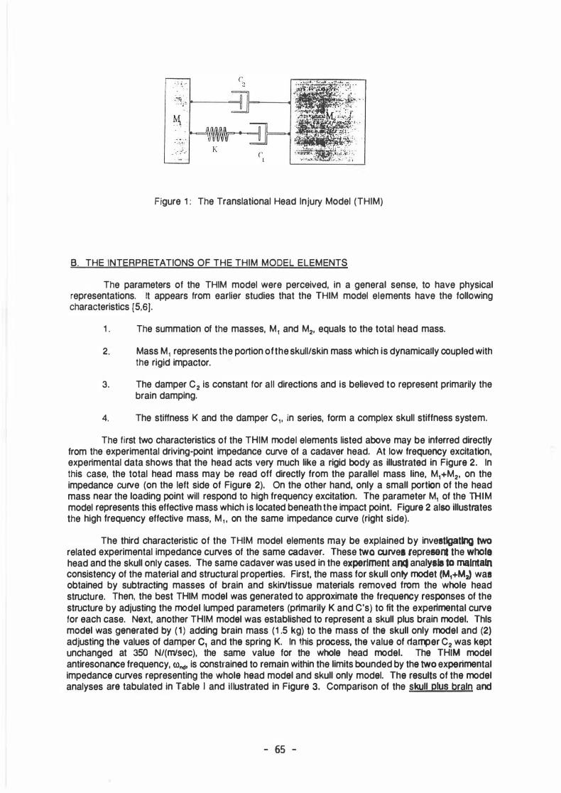
Figure 1 : The Translational Head lnjury Model (THIM)
B. THE INTERPRETATIONS OF THE THIM MODEL ELEMENTS
The parameters of the THIM model were perceived, in a general sense, to have physical representations. lt appears trom earlier studies that the THIM model elements have the following characteristics [5,6].
1 . The summation of the masses, M1 and M2, equals to the total head mass.
2. Mass M1 represents the portion of the skull/skin mass which is dynamically coupled with the rigid impactor.
3. The damper C2 is constant tor all directions and is believed to represent primarily the brain damping.
4. The stiffness K and the damper C1, in series, form a complex skull stiffness system.
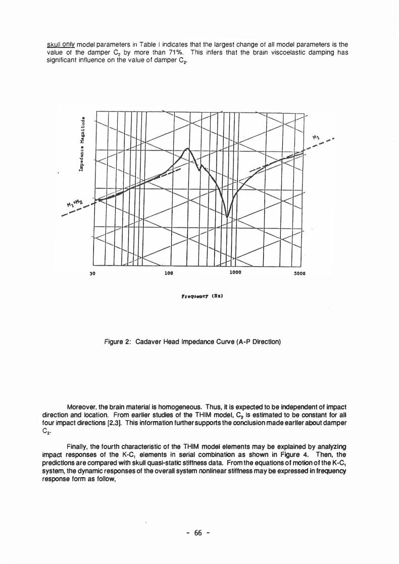
The first two characteristics of the THIM model elements listed above may be interred directly from the experimental driving-point impedance curve of a cadaver head. At low frequency excitatlon, experimental data shows that the head acts very much like a rigid body as illustrated in Figura 2. In this case, the total head mass may be read oft directly from the parallel mass line, M,+M2, on the impedance curve (on the left side of Figura 2). On the other hand, only a small portion of the head mass near the loading point will respond to high frequency excitation. The parameter M1 of the THIM model represents this effective mass which is located beneath the Impact point. Figura 2 also illustrates the high frequency effective mass, M, , on the same impedance curve (right side).
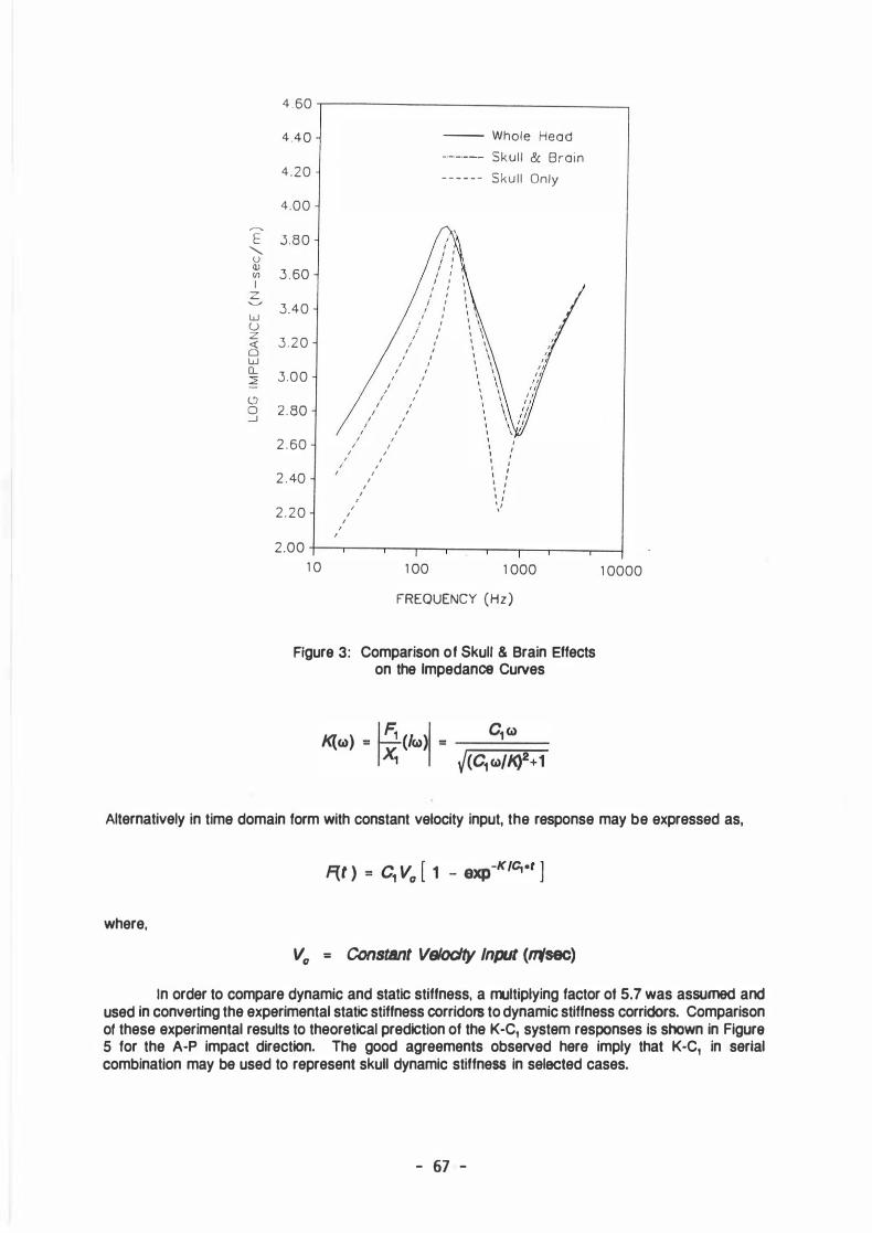
The third characteristic of the THIM model elements may be explained by investlgatlng two related experimental impedance curves of the same cadaver. These two a.uvee represent the whote head and the skull only cases. The same cadaver was used in the expertment anct anatyels to malntatn consistency of the material and structural properties. First, the mass for skull onty modet (M,+MJ was obtained by subtracting masses of brain and skinltissue materials removed from the whole head structure. Then, the best THIM modal was generated to approximata the frequancy responses of the structure by adjusting the model lumped parameters (primarily K and C's) to fit the experimental curva tor each case. Naxt, another THIM modal was established to represent a skull plus brain modal. Thls modal was ganaratad by (1 ) adding brain mass (1 .5 kg) to tha mass of tha skull only modal and (2) adjusting tha values of damper c, and tha spring K. In this process, tha valua of damper C2 was kapt unchanged at 350 N/(m'sec), the same value for the whola head modal. Tha THIM modal antiresonance f requency, rond, is constrained to rernain within the limits bounded by tha two experimental impedanca curves representing the whola haad modal and skull only modal. Tha rasults of tha modal analyses ara tabulated in Table 1 and illustrated in Figura 3. Comparison of the skull plus braln and
- 65 -
skull only modal parameters in Table 1 indicates that the largest change of all modal parameters is the value of the damper C2 by more than 71 %. This infers that the brain viscoelastic damping has signtticant influence on the value of damper C2 .
• u ij "Cl
j
30 100 1000
ruqueacy <Ba>
Figure 2: Cadaver Head lmpedance Curve (A·P Directlon)
Moreover, the brain material is homogeneous. Thus, lt ls expected to be Independent of Impact direction and tocation. From earlier studies of the THIM model, C2 ls estlmated to be constant for all four Impact dlrections (2,3]. This Information further supports the conclusion made eartler about damper C2·
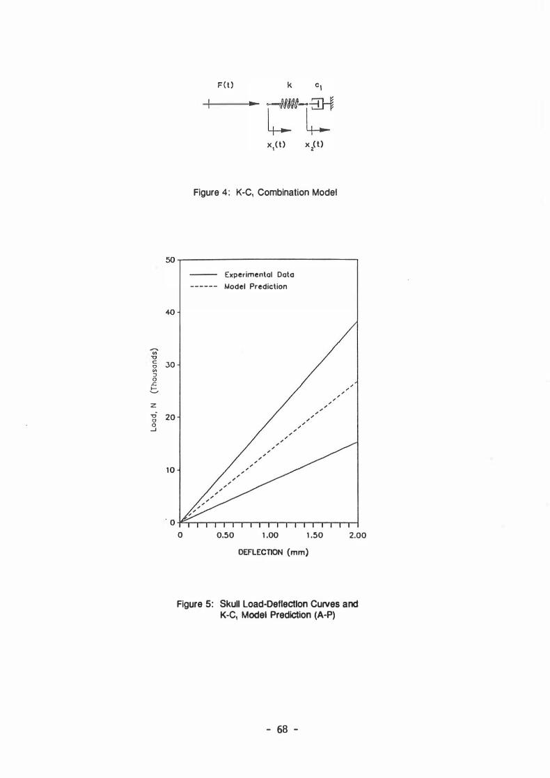
Finally, the fourth characteristic of the THIM model elements may be explained by anatyzing impact responses of the K-C, elements in serial combination as shown in Figura 4. Then, the predictlons are compared with skull quasi-statlc stiffness data. From the equatlons of motion of the K·C, system, the dynamic responses of the overall system nonlinear stiffness may be expressed in frequency response form as follow,
- 66 -
,...._,
E """-
u (1) V1 1
z .._....,
w ü z (§ w Cl.. 2 (.'.) 0 .....1
4.60
4.40
4.20
4.00
3.80
3 . 60
3.40
3 .20
3.00
2 . 80
2 . 60
2 . 40
2.20
2.00 1 0
-- Whole Heod -·-·-·-- Skull & Broin - - - - - - Skul l Only
,
, i i ' ; 1 .
i ' i ' I '
/ 1 1 1
i 1 i 1
1 1 1 1 ' 1
, 1 i 1 ' ' ; 1 ; 1 ' 1 , '
1 1 ' ' I 1 ' , I t I ' / I ' ' I / I /
'
/ I I f
I ' '
I ' I I
I I
1 00
1 ' 1 1 1 1 1 1 1 ' 1 1 1
1 ._,
1 000 FREQUENCY (Hz)
Figura 3: Comparison of Skull & Brain Effects on the lmpedance Curves
1 0000
Alternatively in time domain form with constant velocity input, the response may be expressed as,
where,
V0 = Constant Veloclty Input (ntsec) In order to compare dynamic and static stiffness, a muttiplying factor ot 5.7 was assumed and
used in converting the experimental static stiffness corridors to dynamic stiffness corridors. Comparison ot these experimental resutts to theoretical predictlon of the K-C1 system responses is shown in Figura 5 for the A-P impact directlon. The good agreements observed here imply that K-C, in serial combination may be used to represent skull dynamic stiffness in selected cases.
- 67 -
....... "' "U c 0 "' ::J 0
.r:; 1-._,
z -ü 0 0 _J
JO
20
10
F ( t )
Figure 4: K-C, Combination Model
Experimental Dato
Model Prediction
0 -F-r-r-r-r-T"'""T-r""T"""T""""'lr-T"-r--r-.-..----�-l 0 0.50 1 .00 1 .50 2.00
DEFLECTION (mm)
Figura 5: Skull Load-Deflectlon Curves and K-C, Model Predlction (A-P)
- 68 -
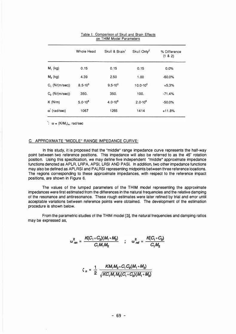
Table 1: Comearison of Skull and Brain Effects on THIM Model Parameters
Whole Head Skull & Brain1 Skull Only2 % Difference (1 & 2)
M1 (kg) 0.15 0.15 0.15 0.0%
M2 (kg) 4.39 2.50 1 .00 -60.0%
C1 (N/(m/sec)) 8.5·103 9.5·103 1 0.0·103 +5.3%
C2 (N/(m/sec)) 350. 350. 1 00. -71 .4%
K (N/m) 5.0·106 4.0·106 2.0·106 -50.0%
<J) (rad/sec) 1 067 1 265 1 4 1 4 +1 1 .8%
: ro • (K/M1)„. rad/sec
C. APPROXIMATE "MIDDLE" RANGE IMPEDANCE CURVE:
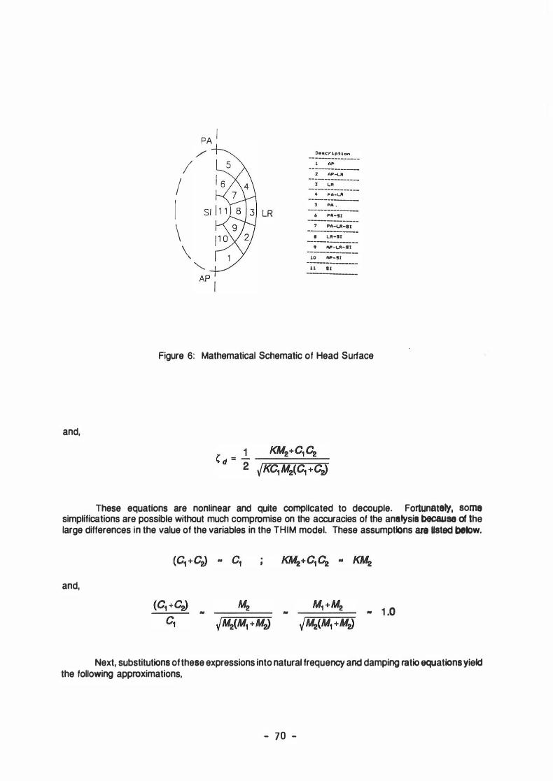
In this study, it is proposed that the "middle" range impedance curve represents the half-way point between two reference posltions. This impedance will also be referred to as the 45· rotation position. Using this specification, we may define five independent "middle" approximate impedance functions denoted as APLR, LRPA, APSI, LRSI AND PASI. In addition, two other impedance functions may also be defined as APLRSI and PALRSI representing midpoints between three reference locations. The regions corresponding to these approximate impedances, with respect to the reference impact positions, are shown in Figura 6.
The values of the lumped parameters of the THIM modal representing the approximate impedances were first estimated from the differences in the natural frequencies and the relative damping ot the resonance and antiresonance. These rough estimates were later refined by trial and error until acceptable variations between reference points were obtained. The development of the estimation procedure is shown below.
From the parametric studies of the THIM modal [3], the natural frequencies and damping ratlos may be expressed as,
K{C1 +CiJ(M1 +MiJ C1M1M2
C = .! KM1M2+C1 C2(M1 +MiJ n 2 yr:-M=C.:-::1 M.=-=-1-=-M.�2('""'C=-1 +""""CiJ�(M.-::-::1:--+�M.':"'":"2)
- 69 -
and,
I ( \
/
\
PA j /
LR
2 Al'-ut 3 �„ 4 PA-ut ' �- . lt PA-91
• Ul-11 • Al'-ul-81
10 Al'-91 11 II
Figura 6: Mathematical Schematic of Head Surf ace
These equations are nonlinear and quite compllcated to decouple. Fortunatety, some simplifications are possible without much compromise on the accuracies of the anatysia because of the large differences in the value of the variables in the THIM modal. These assumptlons are Usted &>ek>w.
and,
• • • 1 .0
Next, substitutions of these expressions into natural frequency and damping ratio equatlons y!eld the following approximations,
- 70 -
2 K(,M1 +M� 2 K WM „ M1M2 WntJ „ -M2 and,
C n „
C2 + yKM1 C d „ _1_ JKM2 2JKM1 2c1 2c1
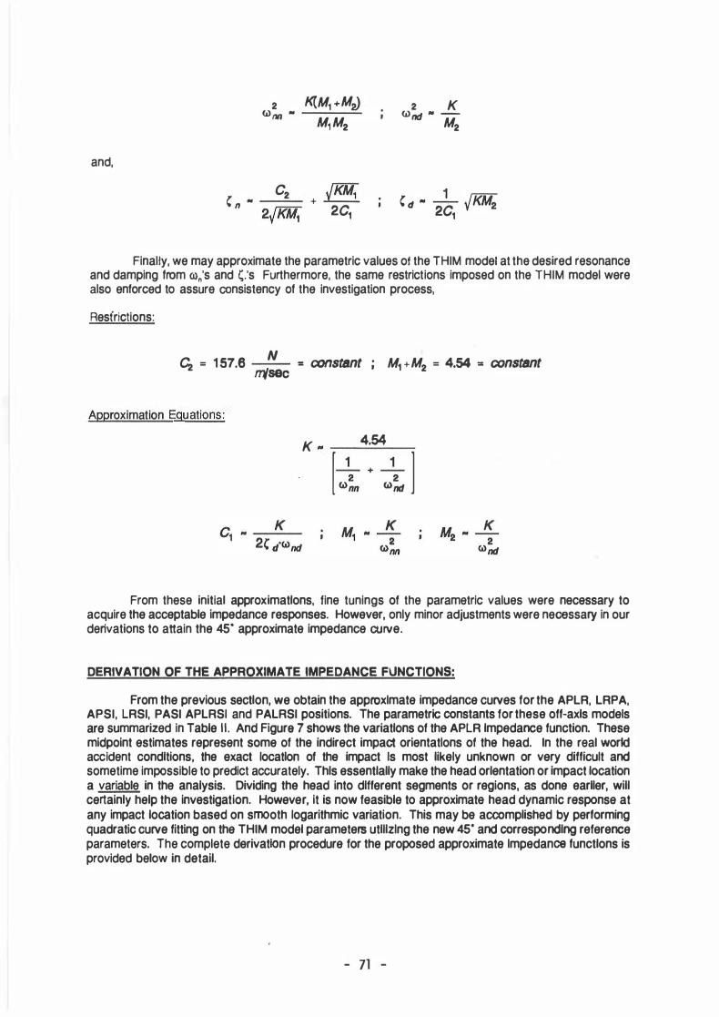
Finally, we may approxlmate the parametric values of the THIM model at the desired resonance and damping from ro"'s and �.'s Furthermore, the same restrictions imposed on the THIM model were also enforced to assure consistency of the investigation process,
Resfrictions:
C2 = 1 57.6 N = constant msec M1 + M2 = 4.54 = constant
Approximation Eguations:
K 4.54 „ ____ _
[ �� + �� l
From these initial approximatlons, fine tunings of the parametric values were necessary to acquire the acceptable impedance responses. However, only minor adjustments were necessary in our derivations to attain the 45• approximate impedance curve.
DERIVATION OF THE APPROXIMATE IMPEDANCE FUNCTIONS:
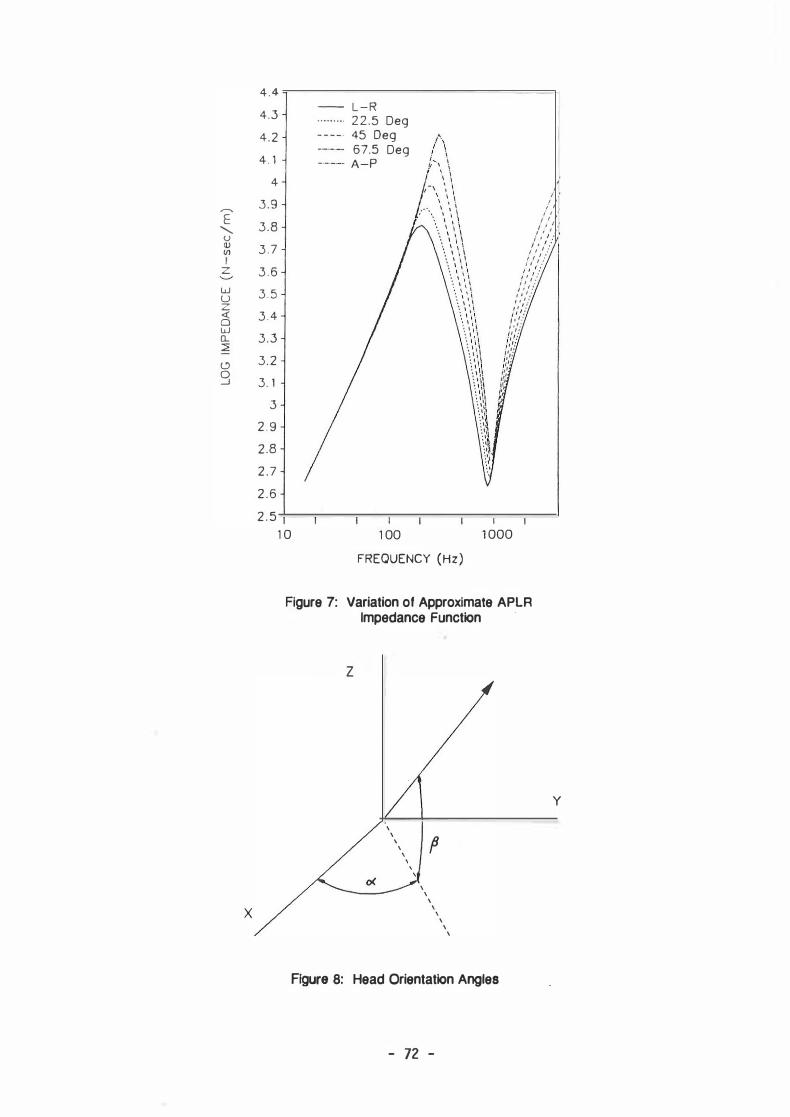
From the previous sectlon, we obtain the approxlmate impedance curves for the APLR, LRPA, APSI, LRSI, PASI APLRSI and PALRSI positions. The parametrlc constants for these off-axls models are summarized in Table II. And Figura 7 shows the variatlons of the APLR lmpedance function. These midpoint estimates represent some of the indirect impact orientatlons of the head. In the real world accident condltions, the exact locatlon of the impact ls most likely unknown or very difficult and sometime impossible to predict accurately. Thls essentlally make the head orlentation or Impact location a variable in the analysis. Dividing the head into dlff erent segments or regions, as done earller, will certainly help the investigation. However, it is now feasible to approximate head dynamic response at any Impact location based on smooth logarithmic variation. This may be accomplished by performing quadratic curve fitting on the THIM model parameters utlllzlng the new 45· and correspondlng reference parameters. The complete derivatlon procedure for the proposed approximate lmpedance functlons is provided below in detail.
- 71 -
4.4 4.3 4.2 4 . 1
4 ,.-.._ 3 . 9 E 3.8 "-() V 3 . 7 Vl 1
z 3 . 6 w 3 . 5 u z <( 0 3.4 w Q_ :::2 3.3 c.::> 3.2 0 _J 3. 1
3 2 . 9 2.8 2 .7 2 .6 2 . 5
X
1 0
L-R 2 2 . 5 Deg 45 Deg 67.5 Deg A-P
1 00 FREQUENCY (Hz)
J I ' I I
i ' 1 I I
/ ,' ,'„
/ ,' ,'/
„ , 1 : , , ' :
; 1 ' :
,' ,' ,'/ , , 1 :
, , , „ , i ' : , , 1 ; ,'/,'/ , , ,„ ; 1 ':
I • , , . f:{ ;1 ' ' i'' i'' i•'
1 000
Figura 7: Variation of Approxlmata APLR lmpedanca Function
·
z
' ' ' ' '
' \
' ' ' ' ' ' ' '
Figura 8: Haad Oriantation Anglas
- 72 -
y
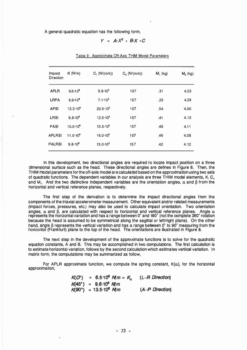
A general quadratic equation has the following form,
Y = A-X2 + B·X + C
Table II: Approximate Off-Axis THIM Model Parameters
Impact K (N/m) C1 (N/(m/s)) C2 (N/(m/s)) M1 (kg) M2 (kg) Direction
APLR 9.6·1 o' 9.9·103 1 57 .31 4.23
LRPA 6.9·1 o' 7. 1 -1 03 1 57 .25 4.29
APSI 1 3.3·109 20.5·103 1 57 .54 4.00
LRSI 9.8·109 1 2.5·103 1 57 .41 4.13
PASI 1 0.0·1 o' 13.5·103 1 57 .43 4.1 1
APLRSI 1 1 .0•108 1 6.0·103 1 57 .46 4.08
PALRSI 9.8·109 13.0·103 157 .42 4.12
In this development, two directional angles are required to locate Impact position on a three dimensional surface such as the head. The
'se directional angles are defines in Figura 8. Then, the
THIM model parameters for the ott-axls model are calculated based on the approxlmatlon uslng two sets of quadratic functlons. The dependent variables in our analysis are three THIM model elements, K, c, and M1• And the two distinctive independent variables are the orientation angles, a and ß from the horizontal and vertical reference planes, respectively.
The f irst step of the derivation is to determine the impact directional angles f rom the components of the triaxial accelerometer measurement. Other equivalent and/or related measurements (impact forces, pressures, etc.) may also be used to calculate Impact orientation. Two orientation angles, a and ß, are calculated wlth respect to horizontal and vertical reference planes. Angle a represents the horizontal variatlon and has a range between o· and 180. (not the complete 3so· rotatlon because the head is assumed to be symmetrical along the saglttal or left/right plane). On the other hand, angle ß represents the vertical varlatlon and has a range between o· to so· measuring from the horizontal (Frankfurt) plane to the top of the head. The orientations are illustrated in Figura 8.
The next step in the development of the approximate functions is to solve for the quadratic equation constants, A and B. This may be accomplished in two computations. The first calculation is to estimate horizontal variation, follows by the second calculation which estimates vertical variation. In matrix form, the computations may be summarized as follow,
For APLR approximate function, we compute the spring constant, K(a), for the horizontal approximation,
K{O') 1<{450) K{900)
= 6.5·108 N/m = K0 = 9.6·108 Nm = 1 3.5·108 N/m
- 73 -
(L-R Dlrsctlon) (A-P Dlrsctlon)
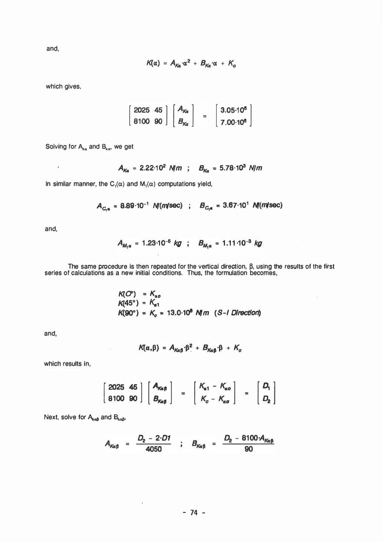
and,
which gives,
[ 3.05·108 l 7.00·108
Solving for A...a and ßi.0, we get
AKa = 2.22·1 02 N/m BKa = 5.78·1<>3 N/m
In similar manner, the C,(a) and M,(a) computations yield,
and,
Ac,cs = 8.89·10-1 N/(msec) ; Bc,cs = 3.67·101 N/(11lsec)
The same procedure is then repeated for the vertical direction, �. using the resutts of the flrst series of calculatlons as a new initial conditions. Thus, the formulation becomes,
K(O') = KCIO 1<(45o) = Ke11 1<(90°) = K0 = 13.0·1<>8 N/m (S-1 Dlrsctlon)
and,
which results in, [ 2025 45 l
[ AKa, l 8100 90 s""'
Next, solve for A...a11 and Bi.a11·
02 - 2·01 4050
=
[ � l
- 74 -

Consequently, C1(cx,ß) and M, (cx,ß) for any impact position on the head surface may also be determined in the same manner (M2 depends only on M1 and c2 is constant. Thus, only K(cx,ß), C1(cx,ß) and M1 (cx,ß) functions are required in the analysis, not all five variables). A computer program is written to calculate these off-axis parameters. Variations of the approximation functlons are shown in Figure 7 for the APLR region. Very good results are observed.
SUMMARY AND CONCLUSION:
In this paper, mathematical approximations of indirect head impact responses were proposed. The off-axis approximation functions assume smooth logarithmic variations of THIM model parameters between reference impact positlons, which were measured experimentally. Seven intermediate lmpedance functlons were generated to represent different impact regions of the head surface. Significant differences on the THIM model parameters were observed for each region. The computatlons of the approximate parameters, K(cx,ß), C1 (cx,ß) and M, (cx,ß) involve two quadratic Interpolations along horizontal and vertical reference planes. Very good results were obtained.
Experimental data is required to verify the prediction of the off-axis THIM model. However, the procedure suggested in this paper can be readily used to calculate a better set of model parameters when new data becomes available.
ACKNOWLEDGEMENTS:
This research program is funded by the National Highway Trafflc Safety Administration (NHTSA) of the U.S. Department of Transportation (USDOT). The experimental and analytical works were conducted at the Vehicle Research and Tests Center (VRTC) of NHTSA in East Llberty, Ohio. The authors also sincerely thank Mr. Jim Hofferberth, the director of VRTC for support and assistance throughout the course of this research.
The opinions and conclusions expressed in this paper are those of the authors and do not necessarily reflect the views or endorsements of EASi Engineering, the Ohio State Universlty, VRTC, NHTSA or USDOT.
REFERENCES:
1 . Stalnaker, R.L., Lin, A.C. and Guenther, D.A., "The Application of the New Mean Strain Criterion (NMSC)," Proceedings of the 1985 International IRCOBl/AAAM Conference on the Biomechanics of Impacts, Goteborg, Sweden, June 1 985, pp. 191 -209
2. Stalnaker, R.L., Low, T.C. and Lin, A.C., "Translational Energy Criteria and lts Correlation With Head lnjury in the Sub-Human Primate," Proceedings of the 1987 International IRCOBI Conference on the Biomechanics of Impacts, Birmingham, U.K., September 1987, pp. 223-238
3. Rojanavanich, V. and Stalnaker, R.L., "Parametric Studies of the Translatlonal Head lnjury Model," Proceedings of the 1988 International IRCOBI Conference on the Biomechanics of Impacts, BergischGladbach, F.R.G., September 1988, pp. 1 81-194
4. McElhaney, J.H., Stalnaker, R.L and Roberts, V.L, "Biomechanical Aspects of Head lnjury,• Proceedings of the Symposium on Human Impact Response, Plenum Press, New York, 1 973, pp. 85-109
5. Stalnaker, R.L. and Rojanavanich, V., "A Practical Application of the Translational Energy Criterla: Evaluation of Baseball and Softball Head Impact lnjury Potentials,• Proceedlngs of the 1990 International IRCOBI Conference on the Biomechanics of Impacts, Bron, France, 1990
6. Rojanavanlch, V., "Development of a Coupled Impact Model and Design Criterion for Evaluation of Bicycle Heimet Effectiveness," Ph.D Dissertation, the Ohio State University, August 1990
- 75 -