Embed Size (px)
Citation preview
page1School of Architecture, Center for Building Performance and Diagnostics @ CMU
Solar Absorption Cooling / Heating System for the Intelligent Workplace
Ming Qu
Sophie Masson
Dr. David Archer
IWESS Workshop Oct.4,2006
School of Architecture, Center for Building Performance and Diagnostics @ CMU Page2
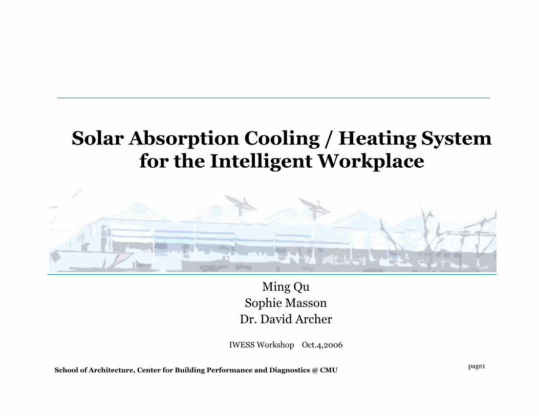
CMPTK-1
Natural Gas
The initial solar heating and cooling system
Para
bolic
Tro
ugh So
lar C
ollector
s
HX-1
TO LOAD
Absorption
Chiller
Coolingtower
Cooling tower
IW solar cooling/heating system
Intelligent
Workplace
One -axis solar
trough
Introduction
School of Architecture, Center for Building Performance and Diagnostics @ CMU Page3
17'5"(5310mm)
12
9@15'9" (9@ 4800 mm)
15
57'7
"(1
7500
mm
)
39'4
"(12
000m
m)
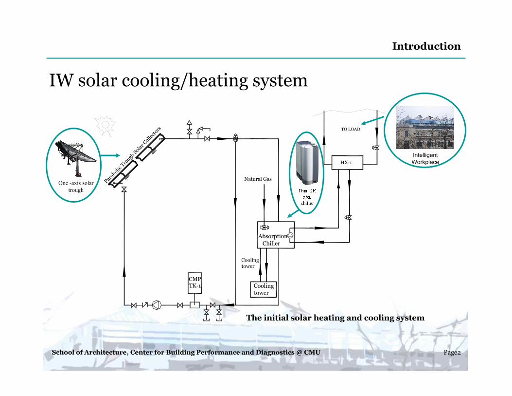
Solar Collectors
Building North
Location of chiller and control box
IW Solar Field Plan
Intelligent workplaceThe Robert L. Preger
Intelligent Workplace� latitude: North 40.26◦
longitude: –79.56◦� Orientation: 15 deviation to
east from the south� area:650 m2 (7,000 ft2)
South zone � area: 245 m2 (2,637 ft2)� 9 offices and 1 conference
space� 30 people
PTSC Orientation� E-W axis
Feb.21 10:50am / 1:10pm
Dec.21 9:10am / 2:50pmJan.21 8:50am / 3:10pmFeb.21 8:00am / 3:50pm
16°
Introduction
School of Architecture, Center for Building Performance and Diagnostics @ CMU Page4
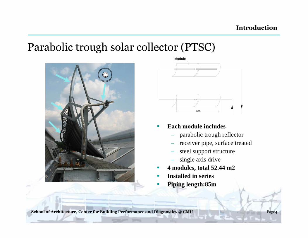
Parabolic trough solar collector (PTSC)
� Each module includes– parabolic trough reflector– receiver pipe, surface treated– steel support structure– single axis drive
� 4 modules, total 52.44 m2� Installed in series� Piping length:85m
Introduction
Module
12m
School of Architecture, Center for Building Performance and Diagnostics @ CMU Page5
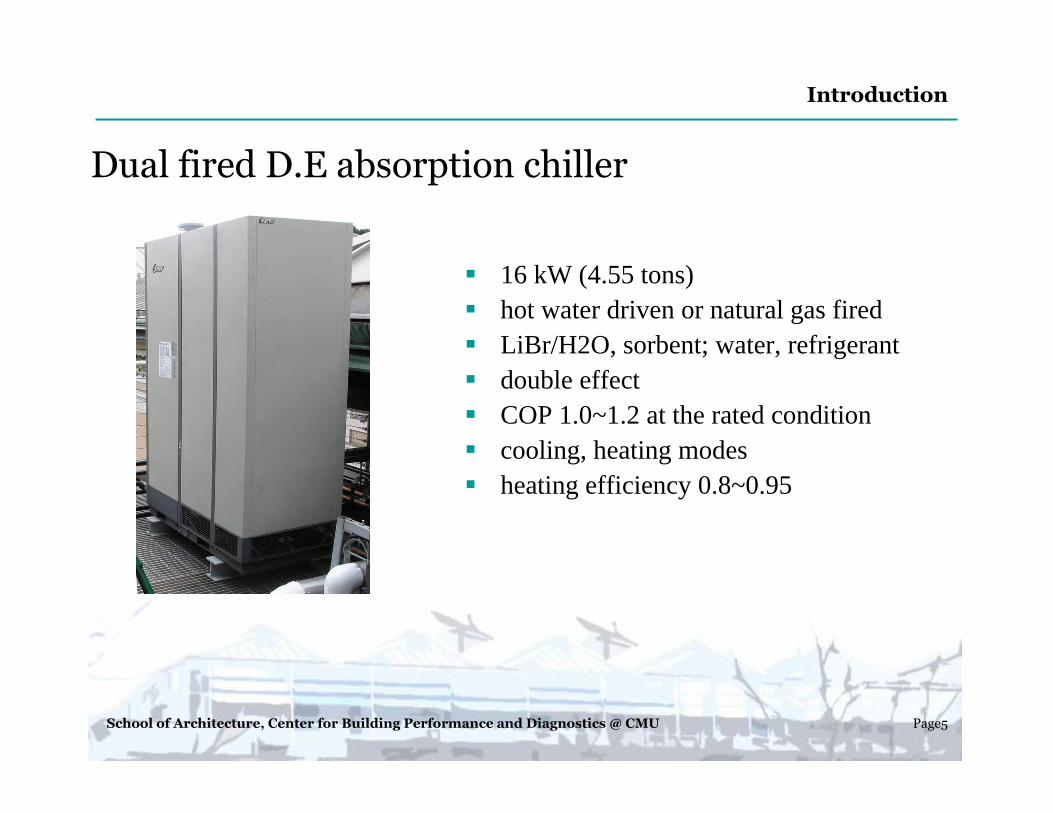
Dual fired D.E absorption chiller
� 16 kW (4.55 tons)� hot water driven or natural gas fired� LiBr/H2O, sorbent; water, refrigerant� double effect� COP 1.0~1.2 at the rated condition� cooling, heating modes� heating efficiency 0.8~0.95
Introduction
School of Architecture, Center for Building Performance and Diagnostics @ CMU Page6
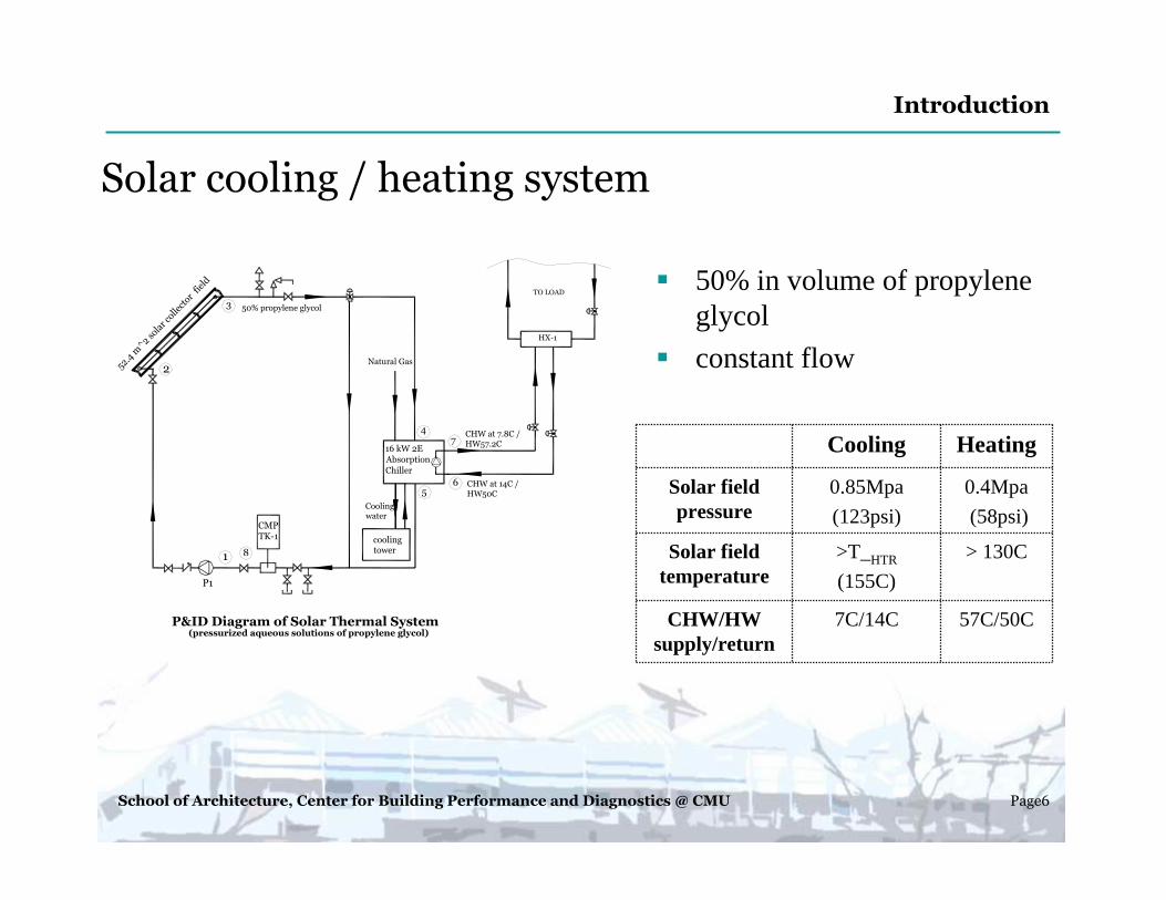
Solar cooling / heating system
� 50% in volume of propylene glycol
� constant flow
57C/50C7C/14CCHW/HW supply/return
> 130C>T_HTR
(155C)
Solar field temperature
0.4Mpa
(58psi)
0.85Mpa
(123psi)
Solar field pressure
HeatingCooling
(pressurized aqueous solutions of propylene glycol)P&ID Diagram of Solar Thermal System
P1
CMPTK-1
2
3
1
6
4
52.4 m
^2 so
lar c
ollector
field
16 kW 2E
Absorption
Chiller
Natural Gas
7
5
8
HX-1
TO LOAD
50% propylene glycol
CHW at 7.8C / HW57.2C
CHW at 14C / HW50C
Coolingwater
cooling tower
Introduction
School of Architecture, Center for Building Performance and Diagnostics @ CMU Page7
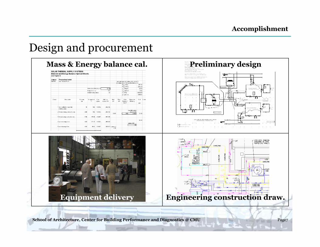
Design and procurement
Engineering construction draw.Equipment delivery
Preliminary designMass & Energy balance cal.
Accomplishment

School of Architecture, Center for Building Performance and Diagnostics @ CMU Page8
System construction and installation
Accomplishment
School of Architecture, Center for Building Performance and Diagnostics @ CMU Page9
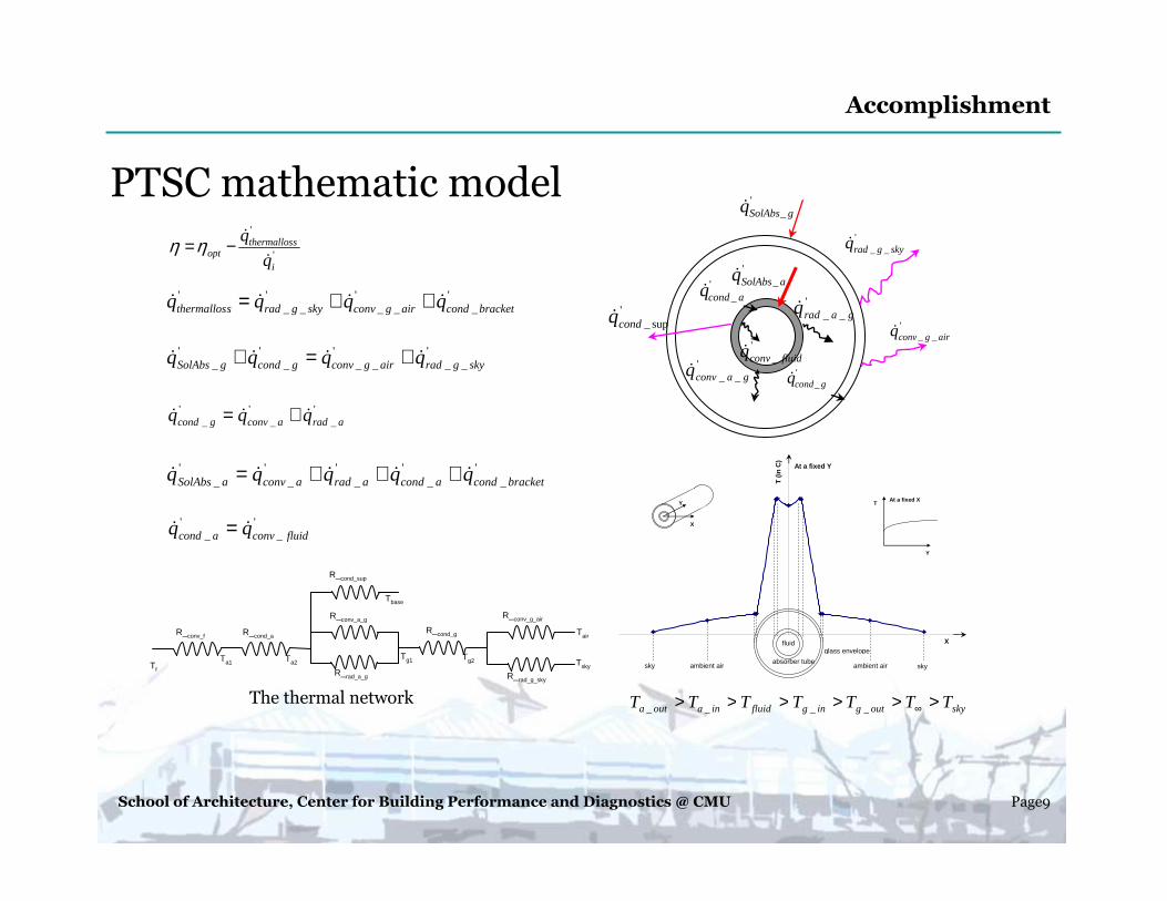
PTSC mathematic model
skyoutgingfluidinaouta TTTTTTT >>>>>> ∞____
'_ gSolAbsq&
'sup_condq&
'__ skygradq&
'_ fluidconvq&
'__ garadq&
'__ gaconvq& '
_gcondq&
'_aSolAbsq&
'__ airgconvq&
'_acondq&
T (
in C
)
fluid
absorber tube
glass envelope
ambient air skyambient airsky
X
At a fixed Y
X
YAt a fixed X
T
Y
Tf
R_conv_f R_cond_a
Ta1 Ta2
Tbase
Tg1 Tg2
Tair
Tsky
R_conv_a_g
R_rad_a_g
R_cond_g
R_conv_g_air
R_rad_g_sky
R_cond_sup
The thermal network
Accomplishment
'
'
i
sthermallosopt q
q&
&−=ηη
'_
'__
'__
'bracketcondairgconvskygradsthermallos qqqq &&&& ++=
'__
'__
'_
'_ skygradairgconvgcondgSolAbs qqqq &&&& +=+
'_
'_
'_ aradaconvgcond qqq &&& +=
'_
'_
'_
'_
'_ bracketcondacondaradaconvaSolAbs qqqqq &&&&& +++=
'_
'_ fluidconvacond qq && =
School of Architecture, Center for Building Performance and Diagnostics @ CMU Page10
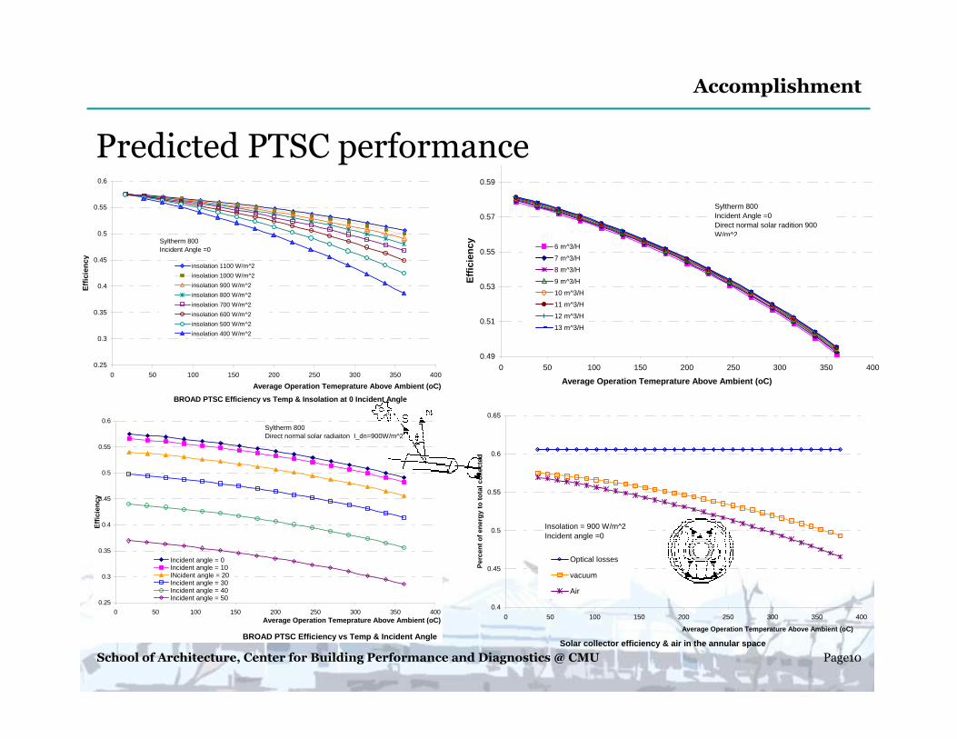
Predicted PTSC performance
Accomplishment
BROAD PTSC Efficiency vs Temp & Incident Angle
0.25
0.3
0.35
0.4
0.45
0.5
0.55
0.6
0 50 100 150 200 250 300 350 400Average Operation Temeprature Above Ambient (oC)
Eff
icie
ncy
Incident angle = 0Incident angle = 10INcident angle = 20Incident angle = 30Incident angle = 40Incident angle = 50
Syltherm 800Direct normal solar radiaiton I_dn=900W/m^2
BROAD PTSC Efficiency vs Temp & Insolation at 0 Incident Angle
0.25
0.3
0.35
0.4
0.45
0.5
0.55
0.6
0 50 100 150 200 250 300 350 400
Average Operation Temeprature Above Ambient (oC)
Eff
icie
ncy
insolation 1100 W/m^2
insolation 1000 W/m^2
insolation 900 W/m^2
insolation 800 W/m^2
insolation 700 W/m^2
insolation 600 W/m^2
insolation 500 W/m^2
insolation 400 W/m^2
Syltherm 800Incident Angle =0
Solar collector efficiency & air in the annular space
0.4
0.45
0.5
0.55
0.6
0.65
0 50 100 150 200 250 300 350 400
Average Operation Temperature Above Ambient (oC)
Per
cen
t o
f en
erg
y to
to
tal c
olle
cted
Optical losses
vacuum
Air
Insolation = 900 W/m^2Incident angle =0
0.49
0.51
0.53
0.55
0.57
0.59
0 50 100 150 200 250 300 350 400
Average Operation Temeprature Above Ambient (oC)
Eff
icie
ncy 6 m^3/H
7 m^3/H
8 m^3/H
9 m^3/H
10 m^3/H
11 m^3/H
12 m^3/H
13 m^3/H
Syltherm 800Incident Angle =0Direct normal solar radition 900 W/m^2
School of Architecture, Center for Building Performance and Diagnostics @ CMU Page11
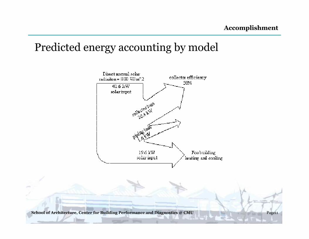
Predicted energy accounting by model
Accomplishment
School of Architecture, Center for Building Performance and Diagnostics @ CMU Page12
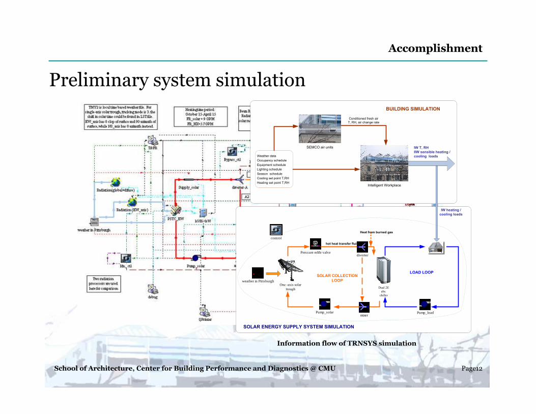
Preliminary system simulation
Accomplishment
hot heat transfer fluid
SOLAR ENERGY SUPPLY SYSTEM SIMULATION
BUILDING SIMULATION
LOAD LOOPSOLAR COLLECTION
LOOP
IW heating /
cooling loads
SEMCO air units
Weather data
Occupancy schedule
Equipment schedule
Lighting schedule
Season schedule
Cooling set point T,RH
Heating set point T,RHIntelligent Workplace
Conditioned fresh air
T, RH, air change rate
IW T, RH
IIW sensible heating /
cooling loads
One -axis solar
trough
Pump_solar
Pressure relife valve
Dual 2E
abs.
chiller
weather in Pittsburgh
Heat from burned gas
diverter
mixerPump_load
control
Information flow of TRNSYS simulation
School of Architecture, Center for Building Performance and Diagnostics @ CMU Page13
Estimated IW solar system performance by system simulation
IW solar cooling and heating system
might cover 39-50% of cooling load and 5-30% heating based on the system simulation.
Accomplishment
School of Architecture, Center for Building Performance and Diagnostics @ CMU Page14
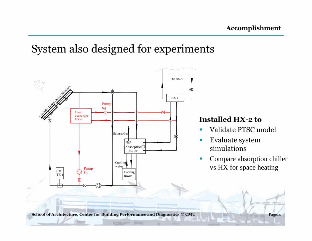
System also designed for experiments
Installed HX-2 to
� Validate PTSC model
� Evaluate system simulations
� Compare absorption chiller vs HX for space heatingPump
S5
Heat
exchanger HX-2
Pump S4
CMPTK-1
Natural Gas
Para
bolic
Tro
ugh So
lar C
ollector
s
HX-1
TO LOAD
Absorption
Chiller
Cooling tower
Cooling water
Accomplishment
School of Architecture, Center for Building Performance and Diagnostics @ CMU Page15
� Integration with cooling and heating devices� Integration of energy supply systems like solar energy, bio-diesel energy
supply system� System simulation including the integration of various energy supply
systems to help design.� Economic of solar cooling and heating� System design, evaluation of a given application
suggestions
Where are we?
Where are we going ?
� Completed system installation� Commissioned the system, solar field has be operated at above 150C
driving 16kW D.E absorption chiller.
Questions?
School of Architecture, Center for Building Performance and Diagnostics @ CMU Page16
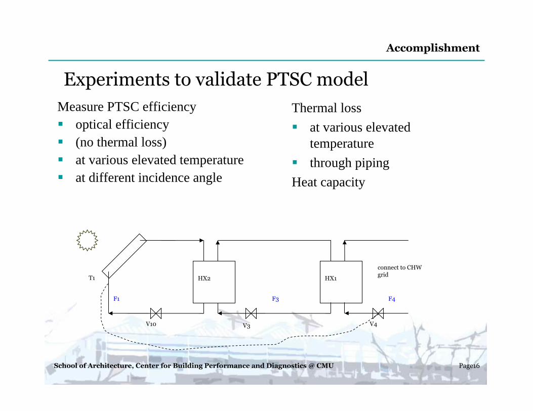
Experiments to validate PTSC model
Measure PTSC efficiency� optical efficiency � (no thermal loss)� at various elevated temperature� at different incidence angle
Thermal loss
� at various elevated temperature
� through piping
Heat capacity
V10 V3 V4
HX2 HX1
connect to CHW grid
T1
F1 F3 F4
Accomplishment
School of Architecture, Center for Building Performance and Diagnostics @ CMU Page17
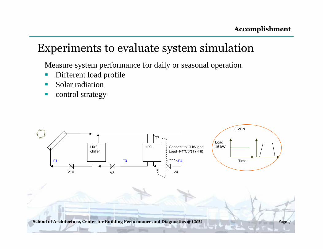
Experiments to evaluate system simulation
Measure system performance for daily or seasonal operation� Different load profile� Solar radiation� control strategy
V10 V3 V4
HX2, chiller
HX1 Connect to CHW gridLoad=F4*Cp*(T7-T8)
F1 F3 F4
T8
T7
Time
Load16 kW
GIVEN
Accomplishment


![[XLS] · Web viewDec06 Nov06 Oct06 Sep06 Aug06 Jul06 Jun06 May06 Apr06 Mar06 Feb06 Jan06 Monthly Market Summary for February 2006 Product Prices Movement % Lots Traded Traded Value](https://img.pdfslide.us/doc/110x75/5b00bb097f8b9af1148d10ee/xls-viewdec06-nov06-oct06-sep06-aug06-jul06-jun06-may06-apr06-mar06-feb06-jan06.jpg)