Embed Size (px)
Citation preview
I n t e r n a t i o n a l T e l e c o m m u n i c a t i o n U n i o n
ITU-T K.56 TELECOMMUNICATION STANDARDIZATION SECTOR OF ITU
(05/2021)
SERIES K: PROTECTION AGAINST INTERFERENCE
Protection of radio base stations against lightning discharges
Recommendation ITU-T K.56

Rec. ITU-T K.56 (05/2021) i
Recommendation ITU-T K.56
Protection of radio base stations against lightning discharges
Summary
Recommendation ITU-T K.56 presents the techniques applied to a telecommunication radio base
station in order to protect it against lightning discharges. The need of protection is obtained from the
methodology contained in IEC 62305-2, which is used to determine the relevant lightning protection
level (LPL) for the installation. The protection techniques for the external area cover the lightning
protection system (LPS), bonding procedures, earthing and the installation of surge protective devices
(SPDs) at the power meter station. The protection techniques for the equipment building cover the
feeder and lighting cables, the electric power conductors, the telecommunication cabling and the
earthing/bonding procedures applied to cable trays and equipment frames. This Recommendation also
provides guidelines in order to achieve adequate protection of the telecommunication equipment based
on the coordination between equipment resistibility, SPD protection level and installation
characteristics.
History
Edition Recommendation Approval Study Group Unique ID*
1.0 ITU-T K.56 2003-07-29 5 11.1002/1000/6500
2.0 ITU-T K.56 2010-01-13 5 11.1002/1000/10443
2.1 ITU-T K.56 (2010) Cor. 1 2017-07-29 5 11.1002/1000/13275
3.0 ITU-T K.56 2021-05-21 5 11.1002/1000/14293
Keywords
Bonding, earthing, lightning protection, radio base station.
* To access the Recommendation, type the URL http://handle.itu.int/ in the address field of your web
browser, followed by the Recommendation's unique ID. For example, http://handle.itu.int/11.1002/1000/11
830-en.
ii Rec. ITU-T K.56 (05/2021)
FOREWORD
The International Telecommunication Union (ITU) is the United Nations specialized agency in the field of
telecommunications, information and communication technologies (ICTs). The ITU Telecommunication
Standardization Sector (ITU-T) is a permanent organ of ITU. ITU-T is responsible for studying technical,
operating and tariff questions and issuing Recommendations on them with a view to standardizing
telecommunications on a worldwide basis.
The World Telecommunication Standardization Assembly (WTSA), which meets every four years, establishes
the topics for study by the ITU-T study groups which, in turn, produce Recommendations on these topics.
The approval of ITU-T Recommendations is covered by the procedure laid down in WTSA Resolution 1.
In some areas of information technology which fall within ITU-T's purview, the necessary standards are
prepared on a collaborative basis with ISO and IEC.
NOTE
In this Recommendation, the expression "Administration" is used for conciseness to indicate both a
telecommunication administration and a recognized operating agency.
Compliance with this Recommendation is voluntary. However, the Recommendation may contain certain
mandatory provisions (to ensure, e.g., interoperability or applicability) and compliance with the
Recommendation is achieved when all of these mandatory provisions are met. The words "shall" or some other
obligatory language such as "must" and the negative equivalents are used to express requirements. The use of
such words does not suggest that compliance with the Recommendation is required of any party.
INTELLECTUAL PROPERTY RIGHTS
ITU draws attention to the possibility that the practice or implementation of this Recommendation may involve
the use of a claimed Intellectual Property Right. ITU takes no position concerning the evidence, validity or
applicability of claimed Intellectual Property Rights, whether asserted by ITU members or others outside of
the Recommendation development process.
As of the date of approval of this Recommendation, ITU had not received notice of intellectual property,
protected by patents/software copyrights, which may be required to implement this Recommendation.
However, implementers are cautioned that this may not represent the latest information and are therefore
strongly urged to consult the appropriate ITU-T databases available via the ITU-T website at
http://www.itu.int/ITU-T/ipr/.
© ITU 2021
All rights reserved. No part of this publication may be reproduced, by any means whatsoever, without the prior
written permission of ITU.
Rec. ITU-T K.56 (05/2021) iii
Table of Contents
Page
1 Scope and purpose ........................................................................................................ 1
2 References..................................................................................................................... 1
3 Definitions .................................................................................................................... 2
3.1 Terms defined elsewhere ................................................................................ 2
3.2 Terms defined in this Recommendation ......................................................... 2
4 Abbreviations and acronyms ........................................................................................ 2
5 Conventions .................................................................................................................. 2
6 Need of protection ........................................................................................................ 2
7 External area ................................................................................................................. 3
7.1 Lightning protection system (LPS) ................................................................ 3
7.2 Bonding in the tower ...................................................................................... 4
7.3 Earthing .......................................................................................................... 6
7.4 Power meter station ........................................................................................ 8
8 Equipment building ...................................................................................................... 9
8.1 Feeder and lighting cables .............................................................................. 9
8.2 Power conductors ........................................................................................... 11
8.4 Earthing and bonding of metallic elements .................................................... 16
9 Protection of RBS equipment ....................................................................................... 18
9.1 Inductive voltage drop across the SPD connecting leads ............................... 19
9.2 Voltage induced in the internal cabling .......................................................... 20
Annex A – Shielding factor (β) of cable trays ......................................................................... 21
Annex B – Shielding factor (η) of building walls .................................................................... 23
Annex C – Example of earthing and bonding configuration inside an RBS ........................... 24
Appendix I – Results of tests with rocket-triggered lightning on a radio base station ............ 25
I.1 Introduction .................................................................................................... 25
I.2 Description of the test site .............................................................................. 25
I.3 Recordings of the lightning current ................................................................ 26
I.4 Shielding factor of tower and feeder tray ....................................................... 26
I.5 Bonding the feeder to the tower at ground level ............................................ 27
I.6 Current flowing through service conductors .................................................. 28
I.7 Inductive voltage drop in the SPD connecting leads ...................................... 29
Bibliography............................................................................................................................. 30

Rec. ITU-T K.56 (05/2021) 1
Recommendation ITU-T K.56
Protection of radio base stations against lightning discharges
1 Scope and purpose
This Recommendation addresses radio base stations (RBSs) made of a shelter or small building to
house the equipment and a nearby tower to hold the antennas. The purpose of this Recommendation
is to provide a set of procedures to protect the RBS against lightning discharges. [b-ITU-T K.71]
gives information on the protection of antenna installations in or on a customer building.
2 References
The following ITU-T Recommendations and other references contain provisions which, through
reference in this text, constitute provisions of this Recommendation. At the time of publication, the
editions indicated were valid. All Recommendations and other references are subject to revision;
users of this Recommendation are therefore encouraged to investigate the possibility of applying the
most recent edition of the Recommendations and other references listed below. A list of the currently
valid ITU-T Recommendations is regularly published. The reference to a document within this
Recommendation does not give it, as a stand-alone document, the status of a Recommendation.
[ITU-T K.12] Recommendation ITU-T K.12 (2010), Characteristics of gas discharge tubes
for the protection of telecommunications installations.
[ITU-T K.27] Recommendation ITU-T K.27 (2015), Bonding configurations and earthing
inside a telecommunication building.
[ITU-T K.35] Recommendation ITU-T K.35 (2020), Bonding configurations and earthing at
remote electronic sites.
[ITU-T K.44] Recommendation ITU-T K.44 (2019), Resistibility tests for telecommunication
equipment exposed to overvoltages and overcurrents – Basic Recommendation.
[ITU-T K.46] Recommendation ITU-T K.46 (2012), Protection of telecommunication lines
using metallic symmetric conductors against lightning-induced surges.
[ITU-T K.47] Recommendation ITU-T K.47 (2012), Protection of telecommunication lines
using metallic conductors against direct lightning discharges.
[ITU-T K.66] Recommendation ITU-T K.66 (2019), Protection of customer premises from
overvoltages.
[ITU-T K.72] Recommendation ITU-T K.72 (2011), Protection of telecommunication lines
using metallic conductors against lightning – Risk management.
[IEC 61643-11] IEC 61643-11:2011, Low-voltage surge protective devices – Part 11: Surge
protective devices connected to low-voltage power systems – Requirements and
test methods.
[IEC 61643-12] IEC 61643-12:2020, Low-voltage surge protective devices – Part 12: Surge
protective devices connected to low-voltage power distribution systems –
Selection and application principles.
[IEC 61643-22] IEC 61643-22:2015, Low-voltage surge protective devices – Part 22: Surge
protective devices connected to telecommunications and signalling networks –
Selection and application principles.
[IEC 62305-1] IEC 62305-1: 2010, Protection against lightning – Part 1: General principles.
[IEC 62305-2] IEC 62305-2:2010, Protection against lightning – Part 2: Risk management.
2 Rec. ITU-T K.56 (05/2021)
[IEC 62305-3] IEC 62305-3:2010, Protection against lightning – Part 3: Physical damage to
structures and life hazard.
3 Definitions
3.1 Terms defined elsewhere
This Recommendation uses the following terms defined elsewhere:
3.1.1 nominal discharge current for class II test (In) [IEC 61643-11]: Crest value of the current
through the SPD having a current waveshape of 8/20.
3.1.2 maximum discharge current (Imax) [IEC 61643-11]: Crest value of a current through the
SPD having an 8/20 waveshape and magnitude according to the manufacturers specification. Imax is
equal to or greater than In.
3.2 Terms defined in this Recommendation
This Recommendation defines the following terms:
3.2.1 cable tray: Rigid structural system used to securely fasten or support cables.
3.2.2 feeder cable: Wave-guide or coaxial cable that conducts signals to an antenna.
3.2.3 lightning protection system (LPS) rod: Metallic rod that makes part of the LPS and is
intended to intercept a lightning strike. It is also designated as "lightning air termination" or "lightning
finial".
3.2.4 radio base station: Installation intended to provide access to the telecommunication system
by means of radio waves.
3.2.5 shielding factor: Factor that represents the attenuation of the voltage or current in a
conductor due to the presence of a nearby shielding conductor.
4 Abbreviations and acronyms
This Recommendation uses the following abbreviations and acronyms:
GDT Gas Discharge Tube
LPL Lightning Protection Level
LPS Lightning Protection System
MEB Main Earthing Bar
PE Protective Earth
RBS Radio Base Station
SPD Surge Protective Device
5 Conventions
None.
6 Need of protection
The risk assessment of the RBS shall be performed according to [IEC 62305-2] in order to determine
a lightning protection level (LPL) for the design of the protection procedures. Table 1 shows some
lightning flash parameters associated with each LPL.
Rec. ITU-T K.56 (05/2021) 3
Table 1 – Lightning flash parameters from [IEC 62305-1]
Parameter Unit LPL
I II III IV
Maximum peak current kA 200 150 100 100
Maximum current rate of rise kA/s 200 150 100 100
Radius of electro-geometric sphere m 20 30 45 60
Probability of flash % 99 98 95 90
NOTE – The risk assessment may indicate an LPL for the design of the LPS that is different from the LPL
considered for the design of the other protection procedures.
7 External area
Figure 1 shows the main earthing and bonding procedures applied to the external area. These
procedures, as well as others not shown in the figure, are detailed in the subsequent clauses.
7.1 Lightning protection system (LPS)
In order to protect the antennas and auxiliary equipment from a direct strike, it may be necessary to
install an LPS in the tower. If the nearby tower does not protect the shelter, it may be necessary to
install an LPS in the shelter too. The assessment of the need for an LPS and the determination of its
positioning shall be performed with the rolling sphere method described in [IEC 62305-3].
The following clauses give some procedures for the installation of the LPS.
7.1.1 Metallic tower
The LPS rod(s) shall be connected directly to the structure of the metallic tower. Therefore, the
structure of the metallic tower will conduct the stroke current to ground and there is no need to install
lightning down conductors.
NOTE – If the total cross-section of the tower structure is less than 125 mm2, then the tower shall be treated
as a non-metallic tower, as described in clause 7.1.2.
7.1.2 Non-metallic tower
If the structure that supports the antennas is not metallic (e.g., wood pole) or if it is metallic but its
cross-section is less than 125 mm2, it is necessary to install two down-conductors to earth the LPS
rod(s). The down conductors shall not be insulated from the tower and they shall have a minimum
cross-section of 50 mm2 each. The down conductors shall be installed on opposite sides of the tower.
7.1.3 Building
In the majority of the cases, the nearby tower will protect the building against direct strikes. However,
the need for an LPS in the building shall be investigated with the rolling sphere method described in
[IEC 62305-3]. If the building requires an LPS, it shall be earthed in the earthing system of the RBS,
which is described in clause 7.3.

4 Rec. ITU-T K.56 (05/2021)
Figure 1 – General view of earthing and bonding procedures in the external area
7.2 Bonding in the tower
7.2.1 Feeder cables
The wave-guide and the external conductor of coaxial cables, henceforth referred as feeder cables,
shall be bonded to the metallic tower (or to the feeder tray) near the antenna, as shown in Figure 1.
A weatherproof connector shall make the connection to the feeder cable in order to avoid corrosion,
and the connection to the tower (or feeder tray) structure shall also be protected to avoid ingression
of moisture. Usually, the cable manufacturers provide appropriated earthing kits for these
connections. The earthing kits shall have a connector to be attached on the bare outer surface of the
feeder (the feeder plastic outer jacket shall be removed), another connector to be attached to the tower
structure (paint shall be removed) and a conductor bonding the two connectors. The earthing kit shall
also contain protective coatings to be applied on the connections. Figure 2 shows schematically the
installation of an earthing kit before the application of the protective coating.
NOTE 1 – For non-metallic towers or metallic towers with a cross-section smaller than 125 mm2, the bonding
shall be made to the lightning down conductor.
NOTE 2 – Some types of antenna are inherently connected to the tower by design. In this case, it is not
necessary to use an earthing kit to bond the feeder to the tower (or feeder tray), as it is already bonded through
the antenna structure.
Rec. ITU-T K.56 (05/2021) 5
Figure 2 – Example of installation of earthing kit on feeder cable
(protective coating not shown)
Depending on the length of the horizontal section of the feeder tray (from the tower to the equipment
building), it is recommended to bond the feeder cables to the tower (or to the feeder tray) at the point
where they leave the tower (bending point). The minimum length of the horizontal section that
requires this bonding is given in Table 2.
Table 2 – Minimum length of the horizontal section of the feeder tray that requires
bonding of feeders at the bending point
LPL I II III-IV
Feeder tray length 10 m 15 m 20 m
NOTE – Regardless of the bonding at the bending point, the feeder cables shall always be bonded to the
bonding bar installed near the feed-through window, as described in clause 7.2.3.
7.2.2 Cable supplying power to the tower lights
The cable used for supplying power to the lights of the tower shall be protected from the lightning
current by one of the options described in this clause. When the power to the lights is supplied by an
equipment (e.g., AC/DC converter), an SPD set may be required close to this equipment, in addition
to the protection measures described in the following.
7.2.2.1 Metallic duct
An unshielded cable should be installed inside a metallic duct and this duct shall be electrically
continuous for its entire length. The duct shall be bonded to the tower at least at its upper end. The
length of cable that may run outside the metallic duct shall be as short as possible. Preferably, the
cable should run inside the metallic duct up to the lighting hardware. The metallic duct can be made
of galvanized steel and shall have a cross-section area not less than 16 mm2. The openings in the duct
shall be adequately sealed in order to prevent the ingression of moisture. The metallic duct shall also
be bonded to the earthing bar installed near the feed-through window.
7.2.2.2 Shielded cable
A shielded cable can be installed directly along the tower, i.e., without a metallic duct. The shield of
the cable shall be electrically continuous for its entire length and shall be bonded to the tower at its
6 Rec. ITU-T K.56 (05/2021)
upper end. The shield shall be terminated as close as possible to the lighting hardware and shall be
bonded to the earthing bar installed near the feed-through window.
7.2.2.3 Unshielded cable
The use of unshielded cable installed without a metallic duct requires the installation of adequate
SPDs close to the lighting hardware and connected between the conductors and the tower structure.
Another set of SPDs is also required at the point where the lighting conductors enters the building
and these SPDs shall be bonded to the earthing bar installed below the feed-through window.
Requirements for these SPDs are given in clause 8.1.2.
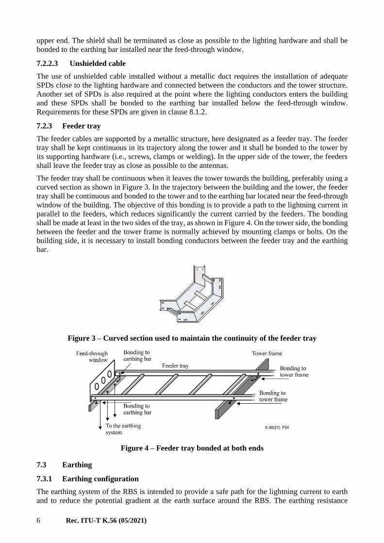
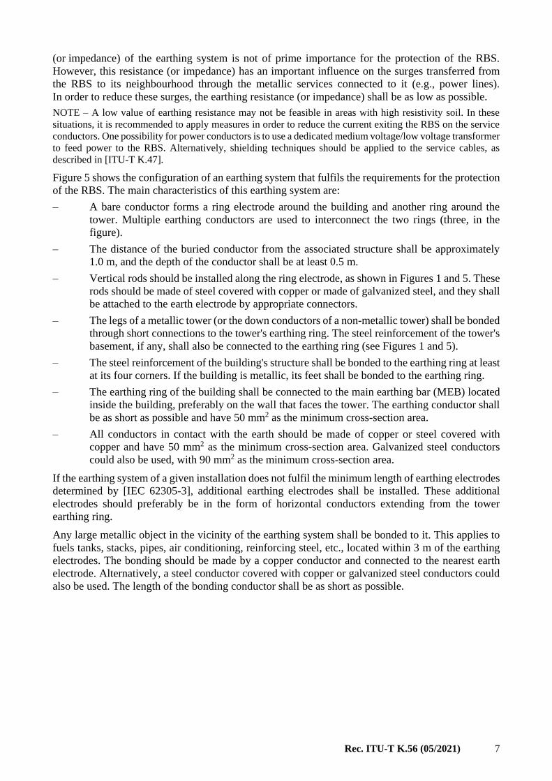
7.2.3 Feeder tray
The feeder cables are supported by a metallic structure, here designated as a feeder tray. The feeder
tray shall be kept continuous in its trajectory along the tower and it shall be bonded to the tower by
its supporting hardware (i.e., screws, clamps or welding). In the upper side of the tower, the feeders
shall leave the feeder tray as close as possible to the antennas.
The feeder tray shall be continuous when it leaves the tower towards the building, preferably using a
curved section as shown in Figure 3. In the trajectory between the building and the tower, the feeder
tray shall be continuous and bonded to the tower and to the earthing bar located near the feed-through
window of the building. The objective of this bonding is to provide a path to the lightning current in
parallel to the feeders, which reduces significantly the current carried by the feeders. The bonding
shall be made at least in the two sides of the tray, as shown in Figure 4. On the tower side, the bonding
between the feeder and the tower frame is normally achieved by mounting clamps or bolts. On the
building side, it is necessary to install bonding conductors between the feeder tray and the earthing
bar.
Figure 3 – Curved section used to maintain the continuity of the feeder tray
Figure 4 – Feeder tray bonded at both ends
7.3 Earthing
7.3.1 Earthing configuration
The earthing system of the RBS is intended to provide a safe path for the lightning current to earth
and to reduce the potential gradient at the earth surface around the RBS. The earthing resistance
Rec. ITU-T K.56 (05/2021) 7
(or impedance) of the earthing system is not of prime importance for the protection of the RBS.
However, this resistance (or impedance) has an important influence on the surges transferred from
the RBS to its neighbourhood through the metallic services connected to it (e.g., power lines).
In order to reduce these surges, the earthing resistance (or impedance) shall be as low as possible.
NOTE – A low value of earthing resistance may not be feasible in areas with high resistivity soil. In these
situations, it is recommended to apply measures in order to reduce the current exiting the RBS on the service
conductors. One possibility for power conductors is to use a dedicated medium voltage/low voltage transformer
to feed power to the RBS. Alternatively, shielding techniques should be applied to the service cables, as
described in [ITU-T K.47].
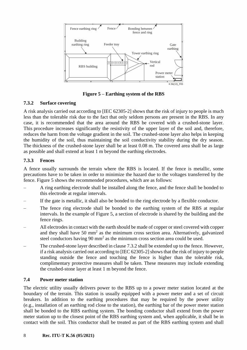
Figure 5 shows the configuration of an earthing system that fulfils the requirements for the protection
of the RBS. The main characteristics of this earthing system are:
– A bare conductor forms a ring electrode around the building and another ring around the
tower. Multiple earthing conductors are used to interconnect the two rings (three, in the
figure).
– The distance of the buried conductor from the associated structure shall be approximately
1.0 m, and the depth of the conductor shall be at least 0.5 m.
– Vertical rods should be installed along the ring electrode, as shown in Figures 1 and 5. These
rods should be made of steel covered with copper or made of galvanized steel, and they shall
be attached to the earth electrode by appropriate connectors.
– The legs of a metallic tower (or the down conductors of a non-metallic tower) shall be bonded
through short connections to the tower's earthing ring. The steel reinforcement of the tower's
basement, if any, shall also be connected to the earthing ring (see Figures 1 and 5).
– The steel reinforcement of the building's structure shall be bonded to the earthing ring at least
at its four corners. If the building is metallic, its feet shall be bonded to the earthing ring.
– The earthing ring of the building shall be connected to the main earthing bar (MEB) located
inside the building, preferably on the wall that faces the tower. The earthing conductor shall
be as short as possible and have 50 mm2 as the minimum cross-section area.
– All conductors in contact with the earth should be made of copper or steel covered with
copper and have 50 mm2 as the minimum cross-section area. Galvanized steel conductors
could also be used, with 90 mm2 as the minimum cross-section area.
If the earthing system of a given installation does not fulfil the minimum length of earthing electrodes
determined by [IEC 62305-3], additional earthing electrodes shall be installed. These additional
electrodes should preferably be in the form of horizontal conductors extending from the tower
earthing ring.
Any large metallic object in the vicinity of the earthing system shall be bonded to it. This applies to
fuels tanks, stacks, pipes, air conditioning, reinforcing steel, etc., located within 3 m of the earthing
electrodes. The bonding should be made by a copper conductor and connected to the nearest earth
electrode. Alternatively, a steel conductor covered with copper or galvanized steel conductors could
also be used. The length of the bonding conductor shall be as short as possible.
8 Rec. ITU-T K.56 (05/2021)
K.56(10)_F05
Fence earthing ring Fence Bonding betweenfence and ring
Buildingearthing ring Feeder tray
Tower earthing ring
Verticalrod
Power meterstation
RBS building
Gateearthing
Figure 5 – Earthing system of the RBS
7.3.2 Surface covering
A risk analysis carried out according to [IEC 62305-2] shows that the risk of injury to people is much
less than the tolerable risk due to the fact that only seldom persons are present in the RBS. In any
case, it is recommended that the area around the RBS be covered with a crushed-stone layer.
This procedure increases significantly the resistivity of the upper layer of the soil and, therefore,
reduces the harm from the voltage gradient in the soil. The crushed-stone layer also helps in keeping
the humidity of the soil, thus maintaining the soil conductivity stability during the dry season.
The thickness of the crushed-stone layer shall be at least 0.08 m. The covered area shall be as large
as possible and shall extend at least 1 m beyond the earthing electrodes.
7.3.3 Fences
A fence usually surrounds the terrain where the RBS is located. If the fence is metallic, some
precautions have to be taken in order to minimize the hazard due to the voltages transferred by the
fence. Figure 5 shows the recommended procedures, which are as follows:
– A ring earthing electrode shall be installed along the fence, and the fence shall be bonded to
this electrode at regular intervals.
– If the gate is metallic, it shall also be bonded to the ring electrode by a flexible conductor.
– The fence ring electrode shall be bonded to the earthing system of the RBS at regular
intervals. In the example of Figure 5, a section of electrode is shared by the building and the
fence rings.
– All electrodes in contact with the earth should be made of copper or steel covered with copper
and they shall have 50 mm2 as the minimum cross section area. Alternatively, galvanized
steel conductors having 90 mm2 as the minimum cross section area could be used.
– The crushed-stone layer described in clause 7.3.2 shall be extended up to the fence. However,
if a risk analysis carried out according to [IEC 62305-2] shows that the risk of injury to people
standing outside the fence and touching the fence is higher than the tolerable risk,
complimentary protective measures shall be taken. These measures may include extending
the crushed-stone layer at least 1 m beyond the fence.
7.4 Power meter station
The electric utility usually delivers power to the RBS up to a power meter station located at the
boundary of the terrain. This station is usually equipped with a power meter and a set of circuit
breakers. In addition to the earthing procedures that may be required by the power utility
(e.g., installation of an earthing rod close to the station), the earthing bar of the power meter station
shall be bonded to the RBS earthing system. The bonding conductor shall extend from the power
meter station up to the closest point of the RBS earthing system and, when applicable, it shall be in
contact with the soil. This conductor shall be treated as part of the RBS earthing system and shall

Rec. ITU-T K.56 (05/2021) 9
have a minimum cross section equal to 50 mm2. In many situations, this bonding is made to the fence's
earthing ring.
Surge protective devices (SPDs) shall be installed at the RBS side of the power meter station
(i.e., downstream of the circuit breakers). These SPDs shall comply with [IEC 61643-11] and
withstand the current:
mn
II LPL
SPD2
= (1)
where:
ISPD is the 10/350 s single-pulse peak current of the SPD
ILPL is the maximum lightning peak current given in Table 1
n is the number of metallic services entering the RBS
m is the number of conductors of the power line.
NOTE – Field experience shows that it is possible to use a device rated for an 8/20 s waveshape, provided it
has an adequate current rating.
The continuous operating voltage (service voltage) of the SPD shall be sufficiently high so that it will
not operate under normal operation or fault conditions of the power line. [IEC 61643-11] provides
guidelines for the selection of the SPD continuous operating voltage.
8 Equipment building
All conductors that enter the equipment building shall be treated in order to limit the voltages and
currents that they can carry to the interior of the building. Furthermore, equipment frames and metallic
ducts and trays shall be adequately earthed and bonded in order to control the surges induced in the
internal cabling. This clause describes the procedures to be applied.
8.1 Feeder and lighting cables
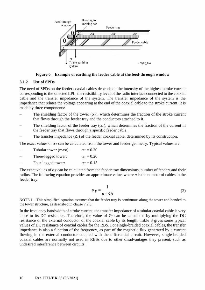
8.1.1 Bonding at the feed-through window
Wave-guides and the outer conductor of coaxial cables shall be directly bonded to the bonding bar
located near the feed-through window. This bonding shall be made by means of short connections
and using a weatherproof connector to make contact with the feeder cable. The cable manufacturers
usually provide appropriate earthing kits for these connections. Figure 6 shows schematically this
installation.
The earthing bar located near the feed-through window shall be connected to the earthing system
through a low-impedance connection. A possibility to achieve a low-impedance connection is to
install parallel conductors between the earthing bar and the earthing electrode (see Figures 1 and 6).
If the conductors supplying power to the tower lights (lighting cable) are installed inside a metallic
duct (see clause 7.2.2.1) or if they are shielded (see clause 7.2.2.2), the metallic duct or the shield
shall be bonded to the earthing bar located near the feed-through window. In both cases, the bonding
shall be made by means of a conductor as short as possible.
10 Rec. ITU-T K.56 (05/2021)
Figure 6 – Example of earthing the feeder cable at the feed-through window
8.1.2 Use of SPDs
The need of SPDs on the feeder coaxial cables depends on the intensity of the highest stroke current
corresponding to the selected LPL, the resistibility level of the radio interface connected to the coaxial
cable and the transfer impedance of the system. The transfer impedance of the system is the
impedance that relates the voltage appearing at the end of the coaxial cable to the stroke current. It is
made by three components:
– The shielding factor of the tower (T), which determines the fraction of the stroke current
that flows through the feeder tray and the conductors attached to it.
– The shielding factor of the feeder tray (F), which determines the fraction of the current in
the feeder tray that flows through a specific feeder cable.
– The transfer impedance (ZT) of the feeder coaxial cable, determined by its construction.
The exact values of T can be calculated from the tower and feeder geometry. Typical values are:
– Tubular tower (mast): T = 0.30
– Three-legged tower: T = 0.20
– Four-legged tower: T = 0.15
The exact values of F can be calculated from the feeder tray dimensions, number of feeders and their
radius. The following equation provides an approximate value, where n is the number of cables in the
feeder tray:
5.3
1
+=
nF (2)
NOTE 1 – This simplified equation assumes that the feeder tray is continuous along the tower and bonded to
the tower structure, as described in clause 7.2.3.
In the frequency bandwidth of stroke current, the transfer impedance of a tubular coaxial cable is very
close to its DC resistance. Therefore, the value of ZT can be calculated by multiplying the DC
resistance of the external conductor of the coaxial cable by its length. Table 3 gives some typical
values of DC resistance of coaxial cables for the RBS. For single-braided coaxial cables, the transfer
impedance is also a function of the frequency, as part of the magnetic flux generated by a current
flowing in the external conductor coupled with the differential circuit. However, single-braided
coaxial cables are normally not used in RBSs due to other disadvantages they present, such as
undesired interference between circuits.

Rec. ITU-T K.56 (05/2021) 11
Table 3 – Typical values of DC resistance of the external conductor of
coaxial feeder cables (ZT)
External diameter (mm) 7.8 10.2 13.7 27.5 39.0 50.3 59.9
DC resistance (/km) 6.6 5.3 3.4 1.04 0.62 0.47 0.31
The peak voltage expected at the end of the feeder cable is given by:
lZIV TFTLPLT αα= (3)
where:
ILPL is the peak lightning current associated with the LPL (see Table 1)
l is the length of the feeder cable.
If VT is higher than the resistibility level of the equipment, then an SPD is necessary close to the
junction between the feeder and the equipment. Otherwise, an SPD is not necessary. The SPD selected
for this application shall not interfere with the radio-frequency signal in the feeder.
If the conductors supplying power to the tower lights are unshielded and installed without a metallic
tube, it is necessary to install SPDs close to the lighting hardware and at the point where the
conductors enter the building, as described in clause 7.2.2.3. These SPDs shall comply with
[IEC 61643-11] and have nominal discharge current rating complying with Table 4. In Table 4 the
recommended maximum discharge current [Imax], if declared, of the SPDs is also provided.
Table 4 – 8/20 s nominal discharge current/recommended maximum discharge current of
SPD for unshielded lighting cable
LPL I II III – IV
Current (kA) 20/40 15/30 10/20
NOTE 2 – If the power to the tower lights is supplied with AC voltage from the electric board, the SPD installed
at the building entrance (on the conductor supplying power to the tower lights) shall be coordinated with the
SPD installed in the electric board. Refer to [IEC 61643-12] for the relevant information.
NOTE 3 – If the power to the tower lights is supplied with DC voltage from an AC/DC converter, an SPD set
may be necessary at the AC/DC converter. Refer to clause 9 in order to assess the need for this SPD set.
8.2 Power conductors
The power conductors can endanger the RBS equipment in case of a lightning flash striking the tower
as well as in case of a flash striking at or near the power line. The protection procedures for any of
these cases consist of limiting the surges between the power conductors and the RBS earthing. The
installation of surge protective devices and the adequate bonding of cable trays and ducts provide
adequate protection.
8.2.1 Electric board
Power conductors shall enter the RBS close to the electric board. The electric board shall contain
circuit breakers, surge protective devices (SPDs) and one earthing bar. The earthing bar shall be
connected to the building ring electrode by a short earthing conductor having a 50 mm2 minimum
cross-section area. The SPD and the board frame shall be connected to the earthing bar. For TN-C
systems, the neutral wire shall also be connected to the earthing bar. Figure 7 shows an example of
an electric board. The following aspects shall be considered:
– If the power cable is shielded, its shield shall be bonded to the electric board's earthing bar.
– Preferably, the power conductors shall leave the electric board inside metallic ducts or trays
that shall be bonded to the board frame. The use of plastic duct to carry the power conductors
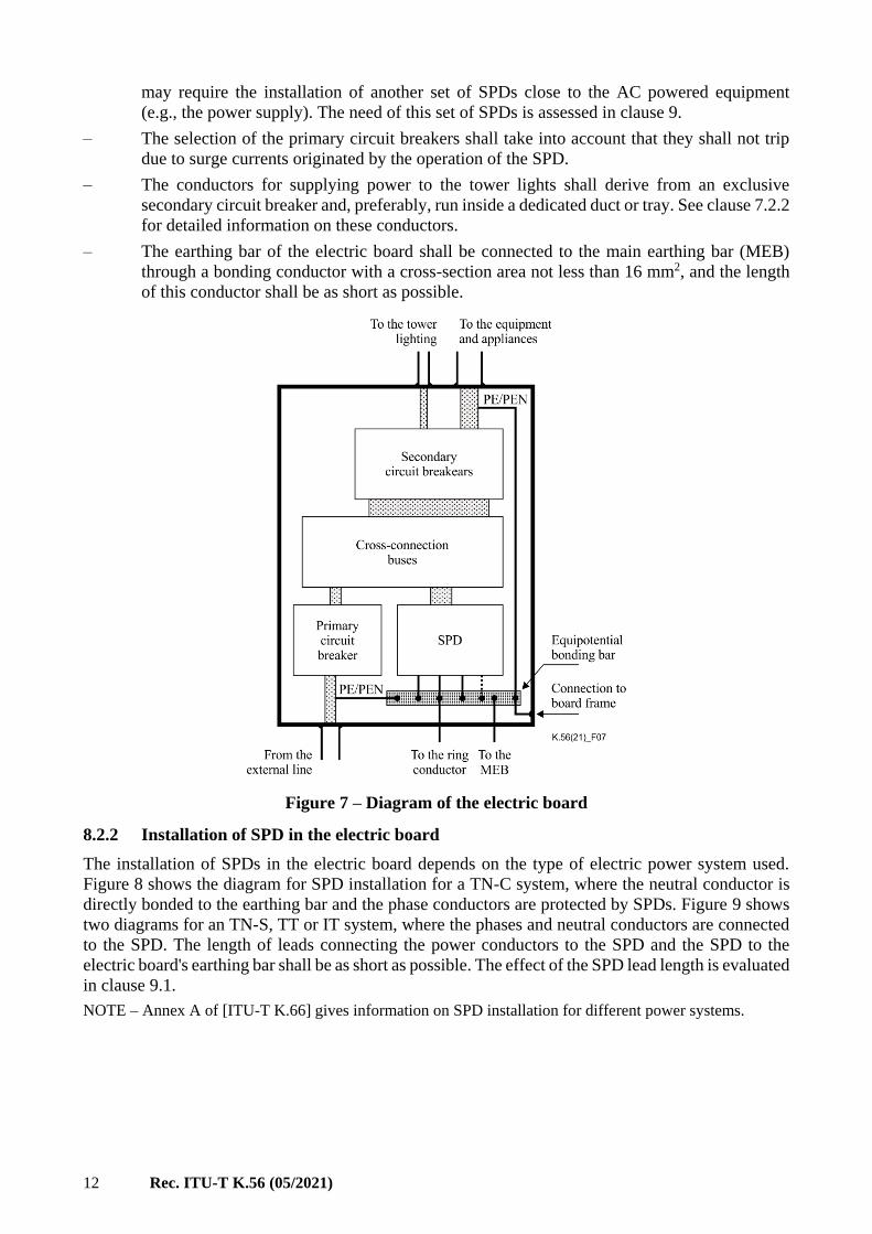
12 Rec. ITU-T K.56 (05/2021)
may require the installation of another set of SPDs close to the AC powered equipment
(e.g., the power supply). The need of this set of SPDs is assessed in clause 9.
– The selection of the primary circuit breakers shall take into account that they shall not trip
due to surge currents originated by the operation of the SPD.
– The conductors for supplying power to the tower lights shall derive from an exclusive
secondary circuit breaker and, preferably, run inside a dedicated duct or tray. See clause 7.2.2
for detailed information on these conductors.
– The earthing bar of the electric board shall be connected to the main earthing bar (MEB)
through a bonding conductor with a cross-section area not less than 16 mm2, and the length
of this conductor shall be as short as possible.
Figure 7 – Diagram of the electric board
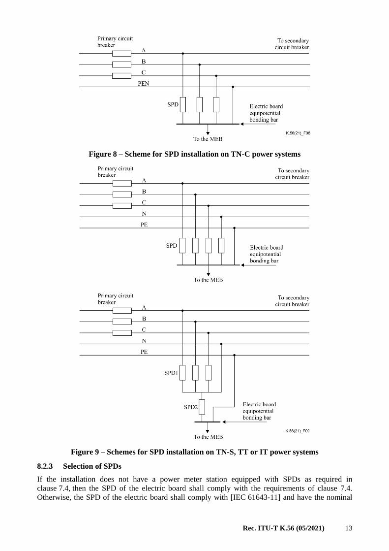
8.2.2 Installation of SPD in the electric board
The installation of SPDs in the electric board depends on the type of electric power system used.
Figure 8 shows the diagram for SPD installation for a TN-C system, where the neutral conductor is
directly bonded to the earthing bar and the phase conductors are protected by SPDs. Figure 9 shows
two diagrams for an TN-S, TT or IT system, where the phases and neutral conductors are connected
to the SPD. The length of leads connecting the power conductors to the SPD and the SPD to the
electric board's earthing bar shall be as short as possible. The effect of the SPD lead length is evaluated
in clause 9.1.
NOTE – Annex A of [ITU-T K.66] gives information on SPD installation for different power systems.
Rec. ITU-T K.56 (05/2021) 13
Figure 8 – Scheme for SPD installation on TN-C power systems
Figure 9 – Schemes for SPD installation on TN-S, TT or IT power systems
8.2.3 Selection of SPDs
If the installation does not have a power meter station equipped with SPDs as required in
clause 7.4, then the SPD of the electric board shall comply with the requirements of clause 7.4.
Otherwise, the SPD of the electric board shall comply with [IEC 61643-11] and have the nominal
14 Rec. ITU-T K.56 (05/2021)
discharge current rating given in Table 5. In Table 5 the recommended maximum discharge current
[Imax], if declared, of the SPD is provided.
Table 5 – 8/20 s nominal discharge current/recommended maximum discharge current of
the electric board SPD
LPL I II III – IV
Current (kA) 30/60 20/40 15/30
NOTE – The current rating of SPD2 in Figure 9 shall be determined considering that it carries the total current
that flows through the service conductors.
The continuous operating voltage (service voltage) of the SPD shall be sufficiently high so that it will
not operate under the normal operation or fault conditions of the power line. [IEC 61643-11] provides
guidelines for the selection of the SPD continuous operating voltage. The SPD installed in the electric
board shall coordinate with the SPD installed in the power meter station (see clause 7.4). Refer to
[IEC 61643-12] for the relevant information to achieve this coordination.
8.3 Telecommunication conductors
The telecommunication conductors can endanger the RBS equipment in case of a lightning flash
striking the tower as well as in case of a flash striking at or near the telecommunication line.
The protection procedures for any of these cases consist of limiting the surges between the
telecommunication conductors and the RBS earthing. The installation of surge protective devices and
adequate earthing of the conductors provides this protection.
NOTE – The procedures for the protection of telecommunication lines against direct and indirect lightning
discharges can be found in [ITU-T K.47] and [ITU-T K.46], respectively, taking into account [ITU-T K.72].
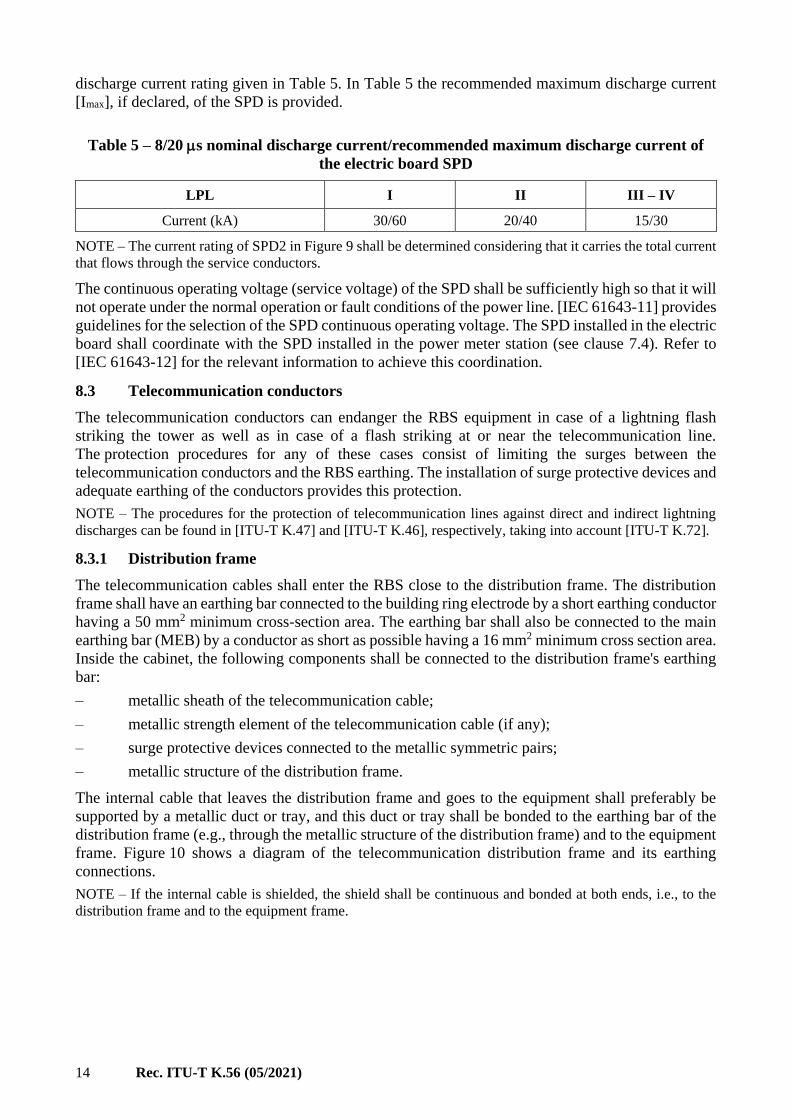
8.3.1 Distribution frame
The telecommunication cables shall enter the RBS close to the distribution frame. The distribution
frame shall have an earthing bar connected to the building ring electrode by a short earthing conductor
having a 50 mm2 minimum cross-section area. The earthing bar shall also be connected to the main
earthing bar (MEB) by a conductor as short as possible having a 16 mm2 minimum cross section area.
Inside the cabinet, the following components shall be connected to the distribution frame's earthing
bar:
– metallic sheath of the telecommunication cable;
– metallic strength element of the telecommunication cable (if any);
– surge protective devices connected to the metallic symmetric pairs;
– metallic structure of the distribution frame.
The internal cable that leaves the distribution frame and goes to the equipment shall preferably be
supported by a metallic duct or tray, and this duct or tray shall be bonded to the earthing bar of the
distribution frame (e.g., through the metallic structure of the distribution frame) and to the equipment
frame. Figure 10 shows a diagram of the telecommunication distribution frame and its earthing
connections.
NOTE – If the internal cable is shielded, the shield shall be continuous and bonded at both ends, i.e., to the
distribution frame and to the equipment frame.

Rec. ITU-T K.56 (05/2021) 15
K.56(10)_F10
Inputframe
Outputframe
(SPD)
Cross-connect
Earthing bar
From theexternal line To the ring
electrodeTo the mainearthing bar
To theequipment
Figure 10 – Diagram of the telecommunication distribution frame
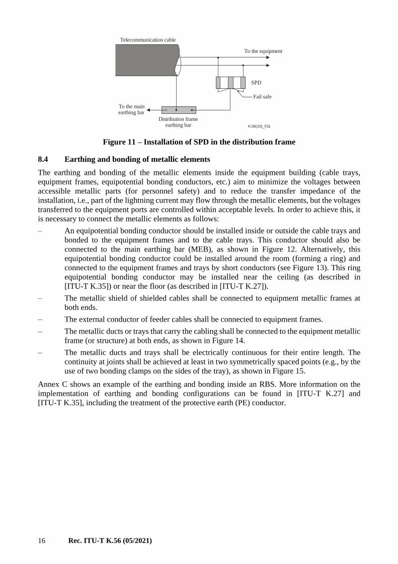
8.3.2 Installation of SPDs in the distribution frame
A three-terminal SPD should be used for symmetric pair lines, as shown in Figure 11. The SPD should
be equipped with a fail-safe device which short-circuits it in case of overheating. The minimum DC
turn-on voltage of the SPD shall be selected by the operator based on the maximum working voltage
that can be applied to the line-to-earth circuit.
NOTE 1 – The minimum DC turn-on voltage should not be too low in order to avoid frequent and unnecessary
operation of the SPD due to distant lightning activity or power-frequency induction, which may reduce the
throughput of the communication channel and the service life of the SPD.
The impulse current rating of the SPD is assessed by the following approximate equation:
( )s
LPLSPD
mmn
II
+=
2 (4)
where:
ISPD is the 10/350 s single-pulse peak current of the SPD
ILPL is the maximum lightning peak current given by Table 1
n is the number of metallic services entering the RBS
m is the number of conductors in the telecommunication cable
mS is the number of conductors equivalent to the shield.
NOTE 2 – Field experience shows that it is possible to use a device rated for an 8/20 s waveshape, provided
it has an adequate current rating.
The value of mS can be obtained by making the resistance of the shield equal to the resistance of mS
conductors. If the cable is unshielded, then mS = 0. A representative value of mS for standard
aluminium shield is mS = 30. For example, for LPL III (ILPL = 100 kA), two services (e.g., power and
telecommunication) and twenty conductors in the telecommunication cable (10 pairs), equation 4
gives ISPD = 500 A.
The capability of the telecommunication conductors to withstand the impulse current shall be
investigated using [ITU-T K.47], and some protection procedures may be necessary in order to
protect the external telecommunication cable.
16 Rec. ITU-T K.56 (05/2021)
K.56(10)_F11
Telecommunication cable
To the equipment
SPD
Fail safe
To the mainearthing bar
Distribution frameearthing bar
Figure 11 – Installation of SPD in the distribution frame
8.4 Earthing and bonding of metallic elements
The earthing and bonding of the metallic elements inside the equipment building (cable trays,
equipment frames, equipotential bonding conductors, etc.) aim to minimize the voltages between
accessible metallic parts (for personnel safety) and to reduce the transfer impedance of the
installation, i.e., part of the lightning current may flow through the metallic elements, but the voltages
transferred to the equipment ports are controlled within acceptable levels. In order to achieve this, it
is necessary to connect the metallic elements as follows:
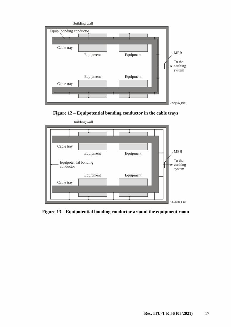
– An equipotential bonding conductor should be installed inside or outside the cable trays and
bonded to the equipment frames and to the cable trays. This conductor should also be
connected to the main earthing bar (MEB), as shown in Figure 12. Alternatively, this
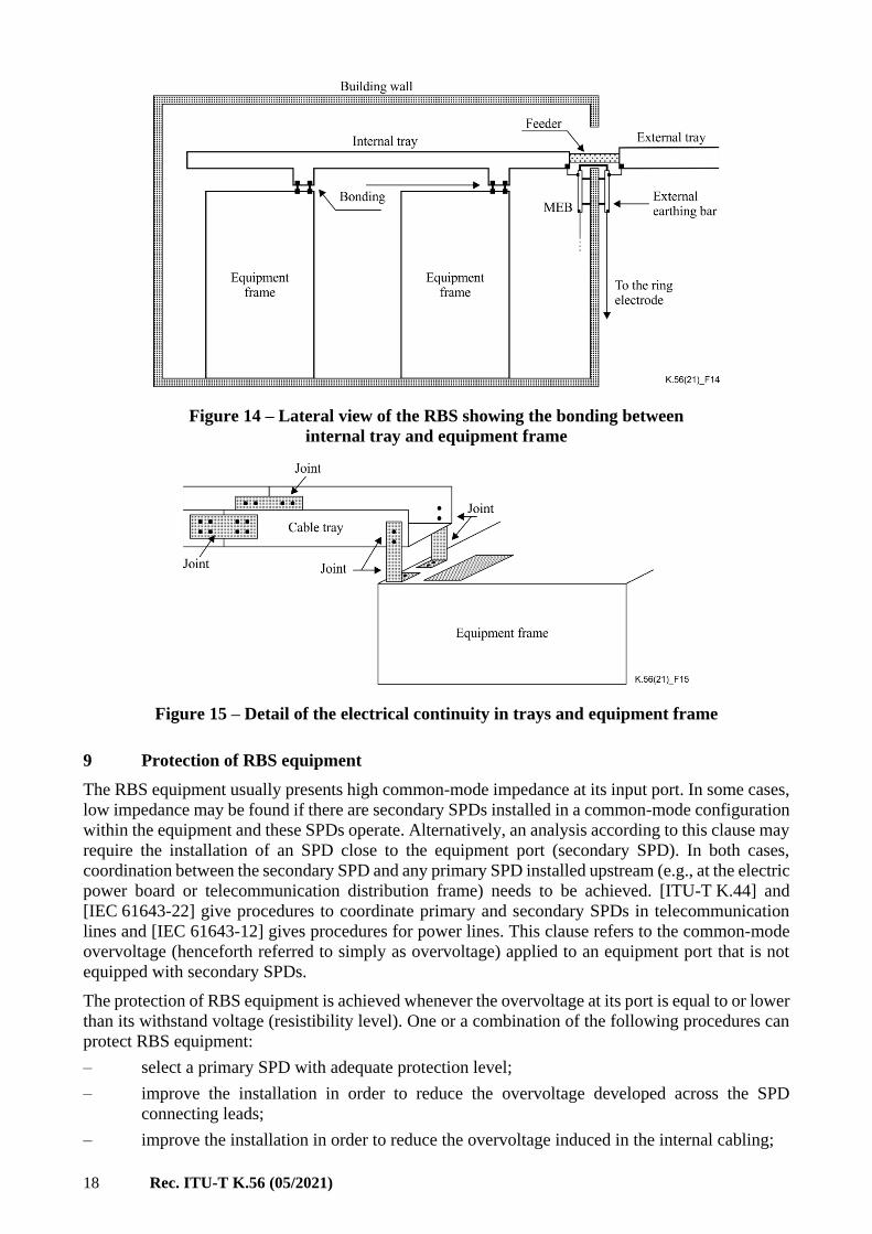
equipotential bonding conductor could be installed around the room (forming a ring) and
connected to the equipment frames and trays by short conductors (see Figure 13). This ring
equipotential bonding conductor may be installed near the ceiling (as described in
[ITU-T K.35]) or near the floor (as described in [ITU-T K.27]).
– The metallic shield of shielded cables shall be connected to equipment metallic frames at
both ends.
– The external conductor of feeder cables shall be connected to equipment frames.
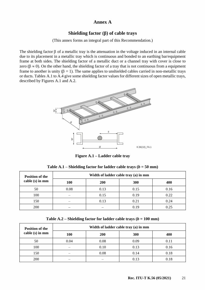
– The metallic ducts or trays that carry the cabling shall be connected to the equipment metallic
frame (or structure) at both ends, as shown in Figure 14.
– The metallic ducts and trays shall be electrically continuous for their entire length. The
continuity at joints shall be achieved at least in two symmetrically spaced points (e.g., by the
use of two bonding clamps on the sides of the tray), as shown in Figure 15.
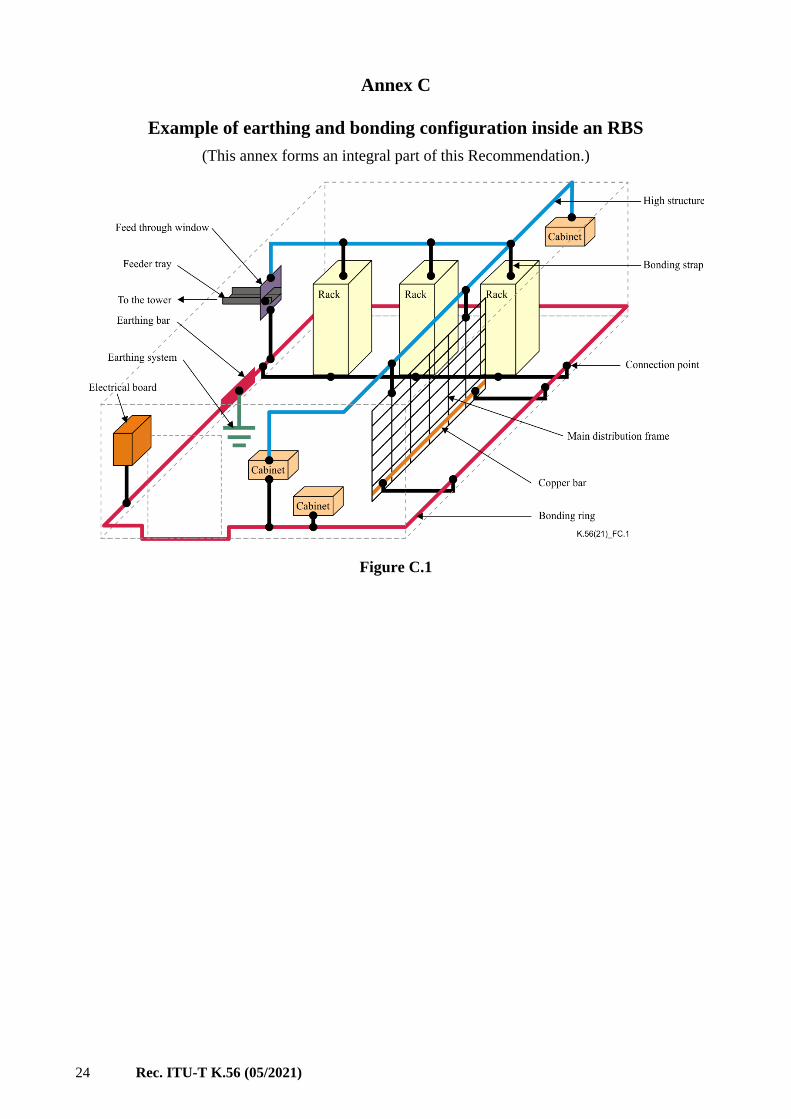
Annex C shows an example of the earthing and bonding inside an RBS. More information on the
implementation of earthing and bonding configurations can be found in [ITU-T K.27] and
[ITU-T K.35], including the treatment of the protective earth (PE) conductor.
Rec. ITU-T K.56 (05/2021) 17
K.56(10)_F12
Equip. bonding conductor
Cable tray
Equipment Equipment
Equipment Equipment
Cable tray
MEB
To theearthingsystem
Building wall
Figure 12 – Equipotential bonding conductor in the cable trays
K.56(10)_F13
Equipotential bondingconductor
Cable tray
Equipment Equipment
Equipment Equipment
Cable tray
MEB
To theearthingsystem
Building wall
Figure 13 – Equipotential bonding conductor around the equipment room
18 Rec. ITU-T K.56 (05/2021)
Figure 14 – Lateral view of the RBS showing the bonding between
internal tray and equipment frame
Figure 15 – Detail of the electrical continuity in trays and equipment frame
9 Protection of RBS equipment
The RBS equipment usually presents high common-mode impedance at its input port. In some cases,
low impedance may be found if there are secondary SPDs installed in a common-mode configuration
within the equipment and these SPDs operate. Alternatively, an analysis according to this clause may
require the installation of an SPD close to the equipment port (secondary SPD). In both cases,
coordination between the secondary SPD and any primary SPD installed upstream (e.g., at the electric
power board or telecommunication distribution frame) needs to be achieved. [ITU-T K.44] and
[IEC 61643-22] give procedures to coordinate primary and secondary SPDs in telecommunication
lines and [IEC 61643-12] gives procedures for power lines. This clause refers to the common-mode
overvoltage (henceforth referred to simply as overvoltage) applied to an equipment port that is not
equipped with secondary SPDs.
The protection of RBS equipment is achieved whenever the overvoltage at its port is equal to or lower
than its withstand voltage (resistibility level). One or a combination of the following procedures can
protect RBS equipment:
– select a primary SPD with adequate protection level;
– improve the installation in order to reduce the overvoltage developed across the SPD
connecting leads;
– improve the installation in order to reduce the overvoltage induced in the internal cabling;

Rec. ITU-T K.56 (05/2021) 19
– install a set of secondary SPDs close to the equipment.
This clause guides the design of the electric installation inside the RBS equipment building in order
to achieve adequate protection of the equipment against lightning discharges. It considers that the
overvoltage applied to the equipment port may have three components:
– the effective protection level of the SPD (UP);
– the peak value of the inductive voltage drop across the SPD connecting leads (UD);
– the peak value of the voltage induced in the cabling section between the SPD and equipment
(UI).
The equipment resistibility is quantified by its withstand voltage UW, which is the voltage that the
equipment can withstand without suffering damage or leading to spark-over of its insulation. It is
considered that there is a safety margin between the value of UW declared by the equipment
manufacturer and the voltage that will produce damage or spark-over, so it is not necessary to
introduce any additional safety margin. Therefore, the equipment is protected whenever the
overvoltage applied to the equipment port is equal to or lower than the withstand voltage declared by
the manufacturer. Depending on the SPD type, one of the following criteria applies:
– For clamping type SPD (e.g., varistor):
IDPW UUUU ++ (5)
– For switching type SPD (e.g., GDT):
IDWIPW UUUUUU ++ and (6)
In the derivation of equations 5 and 6, it is conservatively considered that, for clamping type SPDs,
the voltages UI, UP and UD are simultaneous, while for switching type SPDs, the voltage UI may be
simultaneous with UP or UD. In both cases, it is considered that the voltages UI, UP and UD have the
same polarity. Overvoltage due to the reflection of UI , UP and UD at high impedance equipment ports
is neglected because it is considered that, for typical RBS, the duration of this overvoltage is too short
to cause breakdown of insulation or to impair SPD coordination.
The value of the SPD protection level (UP) is usually provided by its manufacturer in the product data
sheet. For clamping type SPDs (e.g., varistor), the protection level is the voltage across the device
when tested with 8/20 current impulse with a crest value of Iimp (for class I SPDs) or In
(for Class II SPDs). For sparking type SPDs (e.g., GDT), the protection level is the impulse sparking
voltage. The following clauses are aimed to quantify the other parameters involved in the coordination
criteria described in equations 5 and 6.
NOTE – The impulse sparking voltage of GDTs is determined to be under 1 kV/s (see [ITU-T K.12]).
9.1 Inductive voltage drop across the SPD connecting leads
The installation of SPDs in the electric board and in the telecommunication distribution frame shall
minimize the length of the leads connecting the conductor to the SPD and the SPD to the frame/board
earthing bar. If the internal cabling leaves the electric board or the telecommunication distribution
frame in a non-metallic duct, the length of the connecting lead between the frame/board earthing bar
and the MEB shall also be considered. Equation 7 allows the evaluation of the inductive voltage drop
(UD):
( ) mn
lL
td
Id
ZR
RU LDLPL
D+
= (7)
where:
dILPL/dt is the maximum current rate of rise determined by the LPL (see Table 1)

20 Rec. ITU-T K.56 (05/2021)
LD is the inductance per unit length of a connecting lead (LD ≈ 1 μH/m)
lL is the length of the connecting lead
m is the number of line conductors protected with SPDs or directly connected to
the earthing bar at the board/frame (e.g., m = 4 in Figure 8); if a section of the
connecting leads has a single conductor, then m = 1 for this section (e.g., leads
of SPD2 in Figure 9)
n is the number of services connected to the RBS
R is the resistance of the RBS earthing system
Z is the surge impedance of the outside service line (Z = 400 Ω and 100 Ω for aerial
and buried lines, respectively).
9.2 Voltage induced in the internal cabling
If the internal conductors run inside shielded cables and the shield is bonded to the equipment frame
at both ends, the induced voltage can be disregarded (UI = 0). The same applies to unshielded cables
installed inside metallic ducts or closed trays. For unshielded cables installed in metallic open trays,
the magnetic field from the lightning current gives rise to an induced voltage UI, which may be
relevant. This voltage can be calculated by:
+=
d
ldph
td
dIU TLPL
I ln2.0 (8)
where:
dILPL/dt is the maximum current rate of rise determined by the LPL (see Table 1)
h is the height of the cable
is the shielding factor of the walls (see Annex B)
p is a factor to take into account the metallic connection between the tower and the
building (p = 1.5 for a typical RBS)
d is the shortest distance between the tower axis and the cable (see Figure 16)
lT is the length of the cable in a radial direction from the tower (see Figure 16)
is the shielding factor of the cable tray (see Annex A).
K.56(10)_F16
Building wall
Cable
Toweraxis
d lT
Figure 16 – Plan view representation of the distance d and length lT
Rec. ITU-T K.56 (05/2021) 21
Annex A
Shielding factor (β) of cable trays
(This annex forms an integral part of this Recommendation.)
The shielding factor of a metallic tray is the attenuation in the voltage induced in an internal cable
due to its placement in a metallic tray which is continuous and bonded to an earthing bar/equipment
frame at both sides. The shielding factor of a metallic duct or a channel tray with cover is close to
zero ( 0). On the other hand, the shielding factor of a tray that is not continuous from a equipment
frame to another is unity ( = 1). The same applies to unshielded cables carried in non-metallic trays
or ducts. Tables A.1 to A.4 give some shielding factor values for different sizes of open metallic trays,
described by Figures A.1 and A.2.
K.56(10)_FA.1
b
a
s
a
b
Figure A.1 – Ladder cable tray
Table A.1 – Shielding factor for ladder cable trays (b = 50 mm)
Position of the
cable (s) in mm
Width of ladder cable tray (a) in mm
100 200 300 400
50 0.08 0.13 0.15 0.16
100 – 0.15 0.19 0.22
150 – 0.13 0.21 0.24
200 – – 0.19 0.25
Table A.2 – Shielding factor for ladder cable trays (b = 100 mm)
Position of the
cable (s) in mm
Width of ladder cable tray (a) in mm
100 200 300 400
50 0.04 0.08 0.09 0.11
100 – 0.10 0.13 0.16
150 – 0.08 0.14 0.18
200 – – 0.13 0.18

22 Rec. ITU-T K.56 (05/2021)
K.56(10)_FA.2
a
sb
a
b
Figure A.2 – Channel cable tray
Table A.3 – Shielding factor for channel cable trays (b = 50 mm)
Position of the
cable (s) in mm
Width of channel cable tray (a) in mm
100 200 300 400
2.5 0.008 0.006 0.005 0.005
5 0.016 0.012 0.010 0.009
10 0.030 0.024 0.021 0.018
20 0.057 0.047 0.040 0.035
30 0.079 0.069 0.059 0.052
40 0.099 0.088 0.077 0.068
50 0.115 0.107 0.094 0.084
Table A.4 – Shielding factor for channel cable trays (b = 100 mm)
Position of the
cable (s) in mm
Width of channel cable tray (a) in mm
100 200 300 400
2.5 0.005 0.005 0.004 0.004
5 0.010 0.009 0.008 0.008
10 0.020 0.018 0.016 0.015
20 0.038 0.036 0.032 0.029
30 0.053 0.052 0.047 0.043
40 0.066 0.066 0.062 0.057
50 0.080 0.080 0.075 0.070

Rec. ITU-T K.56 (05/2021) 23
Annex B
Shielding factor (η) of building walls
(This annex forms an integral part of this Recommendation.)
Depending on the conductive characteristics of the building walls, they can provide a shielding effect
against electromagnetic fields from lightning, which attenuates the voltages and currents induced
inside the building. This attenuation is represented by the shielding factor . Some shielding factor
values for different shields are summarized in the following:
– Metallic container: η = 0.01. The metallic container shall have its metallic sheaths connected
together at several points along the joints, forming a closed metallic cage (floor, ceiling and
walls).
– Metallic grid: η = w/8.5. The grid width w is in metres and it shall form a cage around the
building (8.5 w 0.085).
– Steel reinforcement of a concrete structure: η = 0.5. The steel reinforcement of a concrete
framework shall be electrically continuous.
– Non-screening: = 1. This applies to walls made of non-conductive materials, such as wood,
bricks and concrete without continuous steel reinforcement.
NOTE – [IEC 62305-2] designates this shielding factor as factor Ks1.
24 Rec. ITU-T K.56 (05/2021)
Annex C
Example of earthing and bonding configuration inside an RBS
(This annex forms an integral part of this Recommendation.)
Figure C.1

Rec. ITU-T K.56 (05/2021) 25
Appendix I
Results of tests with rocket-triggered lightning on a radio base station
(This appendix does not form an integral part of this Recommendation.)
I.1 Introduction
A test site with rocket-triggered lightning in Cachoeira Paulista (Brazil) was active from 2000-2007.
This test site had the participation of several institutions with different research interests, including
the protection of telecommunication installations against lightning. The tests on the
telecommunication installations were carried out under a cooperation among Fundação CPqD
(Brazil), France Telecom R&D (France), Telstra Corp. (Australia), Federal University of Minas
Gerais (Brazil) and University of Campinas (Brazil). Some tests were aimed at the investigation of
the behaviour of a radio base station (RBS) under direct lightning strikes. In order to do that, an RBS
was constructed at the test site, following the guidelines of this Recommendation. A rocket platform
was installed on the top of the tower, in order to trigger the lightning discharges. The tower and the
equipment building were instrumented with current and voltage probes, and oscilloscopes, so that the
overcurrents and overvoltages could be measured at strategic locations. This appendix presents a
summary of the results and compares them with the theoretical predictions from this
Recommendation.
I.2 Description of the test site
The site is described in detail in [b-Barbosa 2], and this clause describes only its main features. The
RBS is a 5 m 6 m masonry building with a 30 m metallic tower nearby, as shown in Figure I.1. The
RBS earthing and bonding system is made according to this Recommendation. At the top of the tower,
there is a rocket platform with the capacity to fire up to four rockets during the same thunderstorm,
which is also shown in Figure I.1. The platform is insulated from the tower, in such way that the
current is forced to pass through a current probe that is connected to a well-shielded oscilloscope
nearby. This oscilloscope is remotely controlled by a fibre-optic link and powered by battery and
solar panel. Another fibre-optic link controls the firing of the rockets. Inside the RBS, there are
oscilloscopes connected to current and voltage probes. The power line that feeds the RBS is made of
three conductors (two phases and one neutral) and the external line has a buried section up to the
power meter station and then an aerial section up to a power generator.
Figure I.1 – General view of the RBS and detail of the rocket
platform on the tower top
26 Rec. ITU-T K.56 (05/2021)
I.3 Recordings of the lightning current
The experiments presented here are related to five flashes successfully triggered from the RBS, with
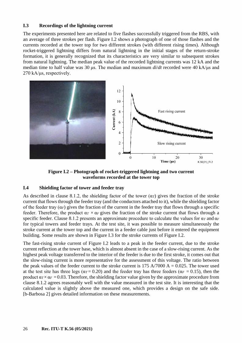
an average of three strokes per flash. Figure I.2 shows a photograph of one of those flashes and the
currents recorded at the tower top for two different strokes (with different rising times). Although
rocket-triggered lightning differs from natural lightning in the initial stages of the return-stroke
formation, it is generally recognized that its characteristics are very similar to subsequent strokes
from natural lightning. The median peak value of the recorded lightning currents was 12 kA and the
median time to half value was 30 μs. The median and maximum di/dt recorded were 40 kA/μs and
270 kA/μs, respectively.
Figure I.2 – Photograph of rocket-triggered lightning and two current
waveforms recorded at the tower top
I.4 Shielding factor of tower and feeder tray
As described in clause 8.1.2, the shielding factor of the tower (αT) gives the fraction of the stroke
current that flows through the feeder tray (and the conductors attached to it), while the shielding factor
of the feeder tray (αF) gives the fraction of the current in the feeder tray that flows through a specific
feeder. Therefore, the product αT × αF gives the fraction of the stroke current that flows through a
specific feeder. Clause 8.1.2 presents an approximate procedure to calculate the values for αT and αF
for typical towers and feeder trays. At the test site, it was possible to measure simultaneously the
stroke current at the tower top and the current in a feeder cable just before it entered the equipment
building. Some results are shown in Figure I.3 for the stroke currents of Figure I.2.
The fast-rising stroke current of Figure I.2 leads to a peak in the feeder current, due to the stroke
current reflection at the tower base, which is almost absent in the case of a slow-rising current. As the
highest peak voltage transferred to the interior of the feeder is due to the first stroke, it comes out that
the slow-rising current is more representative for the assessment of this voltage. The ratio between
the peak values of the feeder current to the stroke current is 175 A/7000 A = 0.025. The tower used
at the test site has three legs (αT = 0.20) and the feeder tray has three feeders (αF = 0.15), then the
product αT × αF = 0.03. Therefore, the shielding factor value given by the approximate procedure from
clause 8.1.2 agrees reasonably well with the value measured in the test site. It is interesting that the
calculated value is slightly above the measured one, which provides a design on the safe side.
[b-Barbosa 2] gives detailed information on these measurements.

Rec. ITU-T K.56 (05/2021) 27
Figure I.3 – Feeder currents for fast-rising (left) and slow-rising
(right) stroke currents
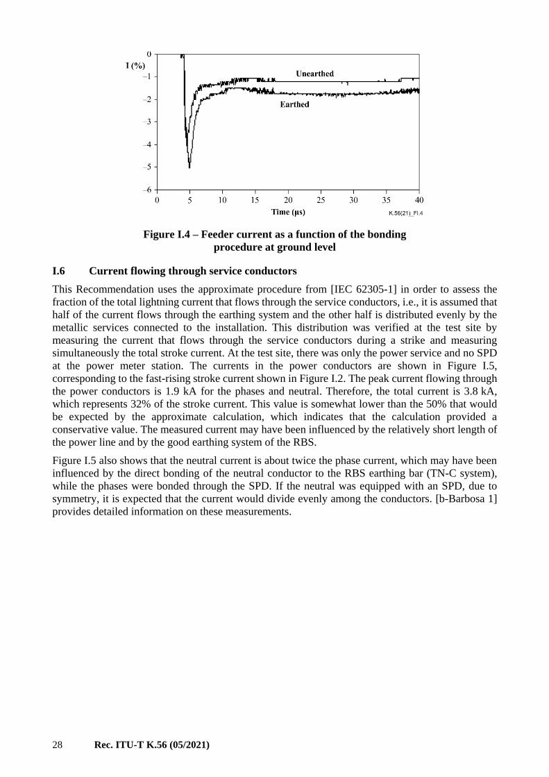
I.5 Bonding the feeder to the tower at ground level
The need to bond the feeders to the tower (or to the feeder tray) at ground level has been investigated
at the test site by measuring the current in the feeder cable with and without this bonding. For each
feeder current measurement, the stroke current at the tower top was simultaneously measured.
Figure I.4 shows the feeder current for the bonded (earthed) and un-bonded (unearthed) conditions.
As each current refers to a different stroke, their amplitudes are normalized by the peaks of the
respective stroke current, which have similar waveforms.
These measurements show that bonding the feeder to the tower at ground level increases the current
in the feeder by about 1/3 or, alternatively, un-bonding the feeder reduces the current by 1/4. This
current change is designated as δi. Therefore, considering only the feeder current, this bonding should
not be done.
However, the voltage between the feeder and the tower frame at the bending point could, under certain
conditions, break down the insulation of the feeder cable. This voltage may be assessed if it is
considered that the feeder/tower voltage is null for the bonded condition and that the un-bonded
condition can be obtained from the bonded condition by injecting –δi in the feeder. The feeder/tower
voltage is then given by the current δi flowing through the inductance between the feeder and the
feeder tray in the horizontal section between the tower and the feed-through window. This inductance
is estimated as being equal to or lower than 0.5 μH/m. The feeder current is estimated as 3% of the
stroke current (it is considered to have three feeders and a three-legged tower). For LPL I, the stroke
current rate of rise is 200 kA/μs, so that the voltage between the feeder and tower is about 1 kV/m.
From the feeder cable data-sheets, the minimum withstand voltage of the feeder outer sheath is
8 kVrms, which gives a 11 kV peak. Therefore, 11 m of tray is necessary to lead to a peak impulse
voltage between the feeder and tower equal to the cable withstand voltage. This value is aligned with
the minimum length of the horizontal section of the feeder tray to require bonding of feeders as given
in Table 2. [b-Barbosa 2] provides detailed information on these measurements.
NOTE – There is a reasonable safety margin between the power-frequency withstand voltage of the cable
insulation and its breakdown voltage under impulse, so the values in Table 2 are conservative.
28 Rec. ITU-T K.56 (05/2021)
Figure I.4 – Feeder current as a function of the bonding
procedure at ground level
I.6 Current flowing through service conductors
This Recommendation uses the approximate procedure from [IEC 62305-1] in order to assess the
fraction of the total lightning current that flows through the service conductors, i.e., it is assumed that
half of the current flows through the earthing system and the other half is distributed evenly by the
metallic services connected to the installation. This distribution was verified at the test site by
measuring the current that flows through the service conductors during a strike and measuring
simultaneously the total stroke current. At the test site, there was only the power service and no SPD
at the power meter station. The currents in the power conductors are shown in Figure I.5,
corresponding to the fast-rising stroke current shown in Figure I.2. The peak current flowing through
the power conductors is 1.9 kA for the phases and neutral. Therefore, the total current is 3.8 kA,
which represents 32% of the stroke current. This value is somewhat lower than the 50% that would
be expected by the approximate calculation, which indicates that the calculation provided a
conservative value. The measured current may have been influenced by the relatively short length of
the power line and by the good earthing system of the RBS.
Figure I.5 also shows that the neutral current is about twice the phase current, which may have been
influenced by the direct bonding of the neutral conductor to the RBS earthing bar (TN-C system),
while the phases were bonded through the SPD. If the neutral was equipped with an SPD, due to
symmetry, it is expected that the current would divide evenly among the conductors. [b-Barbosa 1]
provides detailed information on these measurements.
Rec. ITU-T K.56 (05/2021) 29
Figure I.5 – Currents in the power conductors for the fast-rising stroke current
I.7 Inductive voltage drop in the SPD connecting leads
The surge current flowing through the SPD connecting leads generates an inductive voltage drop in
these leads, which is proportional to the inductance of the leads and the time derivative of the current
flowing through the SPD. Comparing the currents in Figure I.5 to the fast-rising stroke current in
Figure I.2, it is clear that currents in the power conductors have a time-derivative much lower than
the stroke current. [b-Barbosa 1] gives a rationale for assessment of the time derivative of the SPD
current, which is given by:
( ) AVEMAX
+=
dt
di
ZR
R
dtdi SP (I.1)
where:
(diP/dt)MAX is the maximum di/dt on the SPD connecting leads
(diS/dt)AVE is the average di/dt of the lightning stroke current
R is the earth resistance of the installation
Z is the surge impedance of the line.
At the test site, the power line leaves the RBS underground, so that its surge impedance is Z ≈ 100 Ω.
The earthing resistance is R = 20 and the average rate-of-rise of the stroke current is 39 kA/s, for
the fast-rising current of Figure I.2. Inserting these numbers in equation I.1 gives the maximum rate-
of-rise of the current in the power line equal to 6.5 kA/s. This value agrees very well with the sum
of the maximum di/dt measured on the power line conductors, which is given by: 1.7 + 1.7 + 2.8 =
6.2 kA/s. This equation is used in clause 9.1 in order to assess the inductive voltage drop in the SDP
connecting leads.
30 Rec. ITU-T K.56 (05/2021)
Bibliography
[b-ITU-T K.71] Recommendation ITU-T K.71 (2011), Protection of customer antenna
installations.
[b-Barbosa 1] Barbosa C.F., et al (2005), Current distribution on power conductors of an
installation struck by rocket-triggered lightning, Proceedings of the VIII
International Symposium on Lightning Protection, São Paulo, Brazil,
November.
[b-Barbosa 2] Barbosa C.F., et al (2007), Current distribution in a telecommunication tower
struck by rocket-triggered lightning, Proceedings of the IX International
Symposium on Lightning Protection. Foz do Iguaçu, Brazil, November.

Printed in Switzerland Geneva, 2021
SERIES OF ITU-T RECOMMENDATIONS
Series A Organization of the work of ITU-T
Series D Tariff and accounting principles and international telecommunication/ICT economic and
policy issues
Series E Overall network operation, telephone service, service operation and human factors
Series F Non-telephone telecommunication services
Series G Transmission systems and media, digital systems and networks
Series H Audiovisual and multimedia systems
Series I Integrated services digital network
Series J Cable networks and transmission of television, sound programme and other multimedia
signals
Series K Protection against interference
Series L Environment and ICTs, climate change, e-waste, energy efficiency; construction, installation
and protection of cables and other elements of outside plant
Series M Telecommunication management, including TMN and network maintenance
Series N Maintenance: international sound programme and television transmission circuits
Series O Specifications of measuring equipment
Series P Telephone transmission quality, telephone installations, local line networks
Series Q Switching and signalling, and associated measurements and tests
Series R Telegraph transmission
Series S Telegraph services terminal equipment
Series T Terminals for telematic services
Series U Telegraph switching
Series V Data communication over the telephone network
Series X Data networks, open system communications and security
Series Y Global information infrastructure, Internet protocol aspects, next-generation networks,
Internet of Things and smart cities
Series Z Languages and general software aspects for telecommunication systems