Embed Size (px)
Citation preview

INTERNATIONAL TELECOMMUNICATION UNION
CCITT E.121THE INTERNATIONAL TELEGRAPH AND TELEPHONE CONSULTATIVE COMMITTEE
(11/1988)
SERIES E: OVERALL NETWORK OPERATION, TELEPHONE SERVICE, SERVICE OPERATION AND HUMAN FACTORS Operation, numbering, routing and mobile service � International operation � General provisions concerning users
Pictograms and symbols to assist users of the telephone service
Reedition of CCITT Recommendation E.121 published in the Blue Book, Fascicle II.2 (1988)

NOTES
1 CCITT Recommendation E.121 was published in Fascicle II.2 of the Blue Book. This file is an extract from the Blue Book. While the presentation and layout of the text might be slightly different from the Blue Book version, the contents of the file are identical to the Blue Book version and copyright conditions remain unchanged (see below).
2 In this Recommendation, the expression �Administration� is used for conciseness to indicate both a telecommunication administration and a recognized operating agency.
© ITU 1988, 2007
All rights reserved. No part of this publication may be reproduced, by any means whatsoever, without the prior written permission of ITU.

Fascicle II.2 � Rec. E.121 1
Recommendation E.121
PICTOGRAMS AND SYMBOLS TO ASSIST USERS OF THE TELEPHONE SERVICE
1 General definitions and guidelines
1.1 Definitions
pictograms and symbols convey information in pictorial form. They are widely used in the telecommunication field to denote specific types of equipment and services and to instruct people in the use of such equipment and services.
A pictogram is a simplified pictorial representation. It is commonly used to guide people and tell the person how to achieve a certain goal. It consists of more or less realistic elements. Pictograms should be self-explanatory.
A symbol is an abstract pictorial representation; it commonly stands for something and tells a person what he is faced with. It is not necessarily realistic and often requires a learning process in order to be understood.
There is not always a sharp distinction between pictograms and symbols. Pictorial representations can be placed on a continuum with on the one end realistic pictograms which can be readily understood and on the other end abstract symbols which are difficult to understand without prior learning.
1.2 Pictograms and symbols as an alternative to written text
Advantages of pictograms and symbols as compared with written text are:
� independence of language;
� greater efficiency in denoting direction and other special attributes;
� greater spatial compactness;
� faster visual perception;
� more eye-catching.
Disadvantages of pictograms and symbols as compared with written text are:
� less efficiency in conveying detailed information;
� greater risk of incorrect interpretation;
� for abstract symbols, the need of some prior learning in order to be correctly understood.
Pictorial representation of an abstract concept should only be used instead of written text if the user can be assumed to have adequate opportunity for learning (for instance through frequent usage).
To prevent incorrect interpretation, pictograms or symbols may be accompanied by supplementary text. This is especially advisable if correct interpretation could be of vital importance to the user. An additional and important advantage of supplementary text is that it facilitates the learning of symbols and pictograms.
1.3 Guidelines for design
The idea for a pictorial design for a particular application should, whenever possible, be based on the user�s mental picture of that application.
Realistic pictograms are more self-explanatory and require less learning than abstract symbols. Hence, whenever possible, the designer should aim at realistic representation.
To achieve fast visual recognition, a pictogram or symbol should be as simple as possible and it should be easily distinguishable from other currently used pictograms and symbols.
The design of a consistent set of symbols should be guided by a few unambiguous rules about the meaning of pictorial elements within a particular application and the relationship between these elements (see, for example, § 2.5.3). The set should not be larger than strictly necessary; a maximum of three different elements is recommended.
2 Fascicle II.2 � Rec. E.121
The design of pictograms and symbols should meet the technical requirements of their application. If they are to be displayed on the individual keys of a keyboard or on a VDU screen, their design should allow this without essential modification. In both these cases they should be easily recognizable from a distance of 50 cm.
1.4 Guidelines for testing
To find the most suitable symbol or pictogram for a particular application, it is advisable that a number of different designs be generated and submitted for testing.
The method of testing a pictogram or symbol should depend on its intended application. If the application offers little or no opportunity for learning, the test should determine the degree of correct recognition without prior learning. If the application allows prior learning, the test should determine how many trials are needed to arrive at a previously determined criterion of correct recognition. If a pictogram or symbol is to be used in conjunction with other pictograms or symbols, it should be tested within the context of these other symbols of pictograms (see, for an example, Annex A).
1.5 Standardization
Great advantages accrue when the meaning of symbols and pictograms becomes common knowledge. It follows that standardization is desirable, especially when such standardization can be in conformity with existing standards produced by other standards organizations.
1.6 Design specifications
The styling, size, colour and position of each recommended symbol or pictogram is left to the discretion of the Administration. Each symbol or pictogram should, however, bear a close perceptual similarity to those shown in this Recommendation.
Figure titles for Figures 1/E.121 through 4/E.121 and 7/E.121 give those pictorial elements which are considered essential. Symbols may be contained within a suitable frame or border.
2 Specific recommendations
2.1 Symbol for telephone
A symbol for telephone may be used:
a) in place of the word telephone;
b) as an adjunct to a telephone number;
c) to indicate a place where telephone calls can be made;
d) to refer to the telephone service in general.
When such a symbol is used, it should be a representation of a telephone handset. The symbol given here (Figure 1/E.121) is similar to the one cited in [1] and those commonly found on road traffic signs and in railway stations.
FIGURE 1/E.121 Symbol for telephone: telephone handset in upper left-lower right orientation,
with the microphone directed upwards

Fascicle II.2 � Rec. E.121 3
2.2 Symbol for information
A symbol for information can be used in telephone directories, in lists of relevant telephone numbers shown in telephone booths, in other places where information via the telephone can be given, or in printed information for foreign visitors. It may also be used in association with several telephone (service) numbers. It may be used to draw attention to:
a) general telephone service information;
b) information about national or international telephone numbers;
c) assistance in foreign languages;
d) information about hotels, theatres, etc.
When such a symbol is used, it should consist of the letter i (lower case) as shown in Figure 2/E.121. The symbol may be contained within a suitable frame or border. Since this symbol is a general reference, it should be associated with appropriate words or other symbols to show the nature of the information provided at the corresponding telephone number. For example, the symbol �telephone� for general telephone inquiry and the words �English�, �Deutsch�, �Français� for assistance in foreign languages.
FIGURE 2/E.121
Symbol for information (lower case letter �i�)
2.3 Symbols for emergency numbers
In some countries a general emergency number is available to be dialled in all emergency situations. In other countries different telephone numbers are used for each emergency service such as fire brigade, ambulance or police. Where a symbol is used to indicate the general emergency number, that symbol should be �SOS� as shown in Figure 3/E.121. Where no general emergency number exists, the symbol may be used to draw attention to the list of emergency numbers.
FIGURE 3/E.121
Symbol for general emergency number (the letters �SOS� in uppercase)
The symbols shown in Figure 4/E.121 may be used in cases where different symbols are required, possibly in combination with Figure 3/E.121.

4 Fascicle II.2 � Rec. E.121
FIGURE 4/E.121
Symbols for emergency services
Administrations may judge it necessary to test these symbols in the context of other, nationally used, symbols. Annex A provides a method for such a test.
The three symbols in Figure 4/E.121 were selected by means of an international experiment performed in eight countries. Altogether, 364 subjects participated in this experiment. The results of this experiment show a remarkable consistency in the results from the eight countries.
2.4 Graphical representation of audible tones
2.4.1 A graphical representation of audible tones in instructions is recognized as a means, in addition to a verbal description, that could aid telephone users to interpret them correctly during the process of setting up a call. The definition of principles for a graphical representation which would guarantee the maximum aid to users has been studied during the Study Period 1977-1980. Certain experiments designed by Working Party II/2 have been carried out with the participation of the following countries: Australia, Canada, Denmark, the Netherlands, Nigeria, Norway, Sweden and the United Kingdom.
2.4.2 An additional study has been done during the Study Period 1981-1984 in the United Kingdom. This study supported results of earlier studies.
2.4.3 Audible tones known to exist at the present time in various national networks can be characterized by the following factors:
� temporal structure,
� pitch,
� tone quality or timbre (subjectively felt by the users and related to the spectral complexity),
� loudness.
Fascicle II.2 � Rec. E.121 5
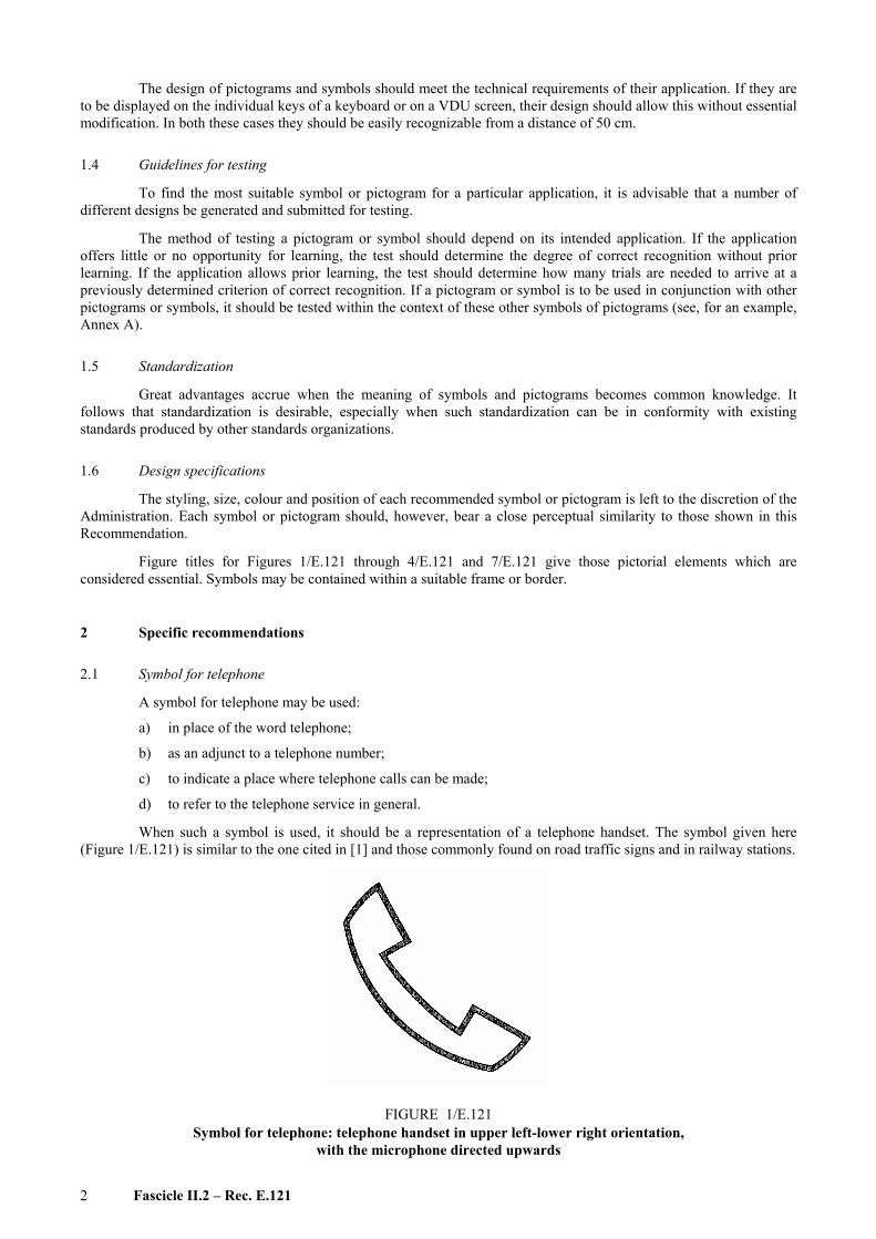
These four factors should be graphically represented according to the following principles:
2.4.3.1 Temporal structure
This factor should be represented by appropriate blank intervals along a horizontal time axis.
For example:
2.4.3.2 Pitch variation in a tone
This factor should be represented by the vertical displacement of a linear element above the time axis.
2.4.3.3 Tone quality
Pure tones (sinusoidal waves) should be represented by linear elements on a horizontal axis.
If non-pure tones consist of two frequencies, the optimal representation depends on the frequency difference between the tones. This frequency difference may be greater than the critical bandwidth (consonant tone-pairs) or smaller (dissonant tone-pairs) [2]; for consonant tone-pairs, the optimal representation is two parallel linear elements; for dissonant tone-pairs, a wavy line is optimal.
If the frequency difference between the two tones is near the critical bandwidth, neither of the representations may be satisfactory.
2.4.3.4 Loudness variation in the tone
This factor should be represented by variation in the thickness of a linear element.
2.4.4 Intermittent tones should normally be represented by at least 2 full cycles.
2.4.5 The same time scale should be used in the representation of all tones in the same figure.
2.5 Symbols for supplementary services
2.5.1 Symbols may be used to designate telephone subscriber services. They may appear on subscriber equipment, e.g. on the tops of push-buttons by which these services are operated. They may also be used in instructional material1). A symbol has the advantage � contrary to a name or an abbreviated name � of being independent of language. For users familiar with a certain language, the full name or a mnemonic code may be more easily understood.
____________________ 1) At the time these symbols were developed and tested, the procedures by which subscriber services are operated were not yet
standardized. This may lead to the undesirable situation that the same symbol is used for different procedural implementations of a service. Efforts have therefore to be made to standardize the operational procedures for supplementary services.

6 Fascicle II.2 � Rec. E.121
2.5.2 Figure 5/E.121 shows symbols for twelve supplementary services. The names of the services and their descriptions are those used in the experiments in which the symbols were evaluated (see Annex B). They are chosen in such a way that they explain the operation of the services in clear and simple terms. Where applicable, the corresponding names as they appear in Supplement No. 1 are added in parentheses, together with the relevant paragraph numbers.
2.5.3 The set of symbols recommended here is open to future expansion, if symbols for more services should be required.
The majority of the standardized symbols are based on the following guiding principles:
� a point represents a subscriber�s station;
� a line between points represents a connection between subscribers;
� a dashed line represents a connection on the hold;
� an arrow represents a call:
outgoing calls . . . . an arrow away from the user ↑
incoming calls . . . . an arrow toward the user ↓
calls passing by . . . . an arrow passing by the user →
Example: Basic diversion (�Incoming call passes by�)
Example: Enquiry call (�First party on hold whilst calling another party�)
� a bar (or �barrier�) represents a �stop� for a call;
Example: Incoming calls barred
� a repeated action is represented by repeated symbol elements;
Example: Repeat last call
� ringing is represented by stylized sound waves outgoing from a point;
Example: No reply diversion
The number of symbols combining these elements is limited. Therefore, for some of the standardized symbols, additional elements have had to be applied:
� a keystroke is represented by a square;
Example: Short code dialling (�One keystroke instead of many�)
� a disconnection is represented by an interrupted line;
Example: Disconnect

Fascicle II.2 � Rec. E.121 7
2.5.4 If manufacturers or Administrations consider using symbols which are not yet recommended, they are advised to contact the CCITT Secretariat, which will in turn contact the Special Rapporteur for the relevant Question.
2.5.5 The symbols presented in Figure 5/E.121 may also be displayed on a CRT as long as they appear closely similar to their presentation on paper. On a commonly available CRT screen, this can be achieved by using a minimum of 60 × 50 or 60 × 60 pixels per symbol.
2.6 Pictographic instructions for payphones
A sequence of pictograms is an effective means of instructing users of payphones, especially if certain users, e.g. foreign visitors, are not familiar with the equipment or operating procedures. Various studies on the design of pictographic instructions for payphones have led to the following guidelines:
2.6.1 If it is likely that certain users will be unfamiliar with the equipment (e.g. foreign visitors), realistic drawings showing the equipment sufficiently to locate the different parts would be helpful; where it is likely that users will be familiar with the equipment, or that locating the different elements is not a problem, less representative pictograms may be acceptable.
2.6.2 Movement (or certain actions) should be indicated by arrows. These could be provided in a different colour from the rest of the pictogram, for greater conspicuousness.
2.6.3 Movement, or actions, in a sequence of pictographic instructions, should be labelled by numbers 1, 2, 3, etc. in the appropriate order.
Pictograms can be arranged in a horizontal strip (as illustrated in Figure 6/E.121) or in a vertical column, or (provided that the numbering is clear), in a block.
2.6.4 Pictograms should be placed where they will most easily be seen by the user and, wherever possible, should be fastened to the body of the equipment. Ideally, new payphones should be designed with a space on the front specifically to accommodate the pictograms, and the larger the space allowed, the better.
2.6.5 New pictogram designs should be tested in realistic conditions on a sample of the user population before being implemented generally.
2.7 Symbol for facsimile
A symbol for facsimile may be used:
a) in place of the word facsimile;
b) to indicate a place where a facsimile service can be used;
c) to refer to the facsimile service in general;
d) as an adjunct to the facsimile number of a subscriber (see also Recommendation E.123, § 7).
When such a symbol is used, it should consist of the word FAX in capital letters as indicated in Figure 7/E.121.

8 Fascicle II.2 � Rec. E.121
FIGURE 5/E.121
Symbol for supplementary services

Fascicle II.2 � Rec. E.121 9
FIGURE 6/E.121
Example of pictographic instructions
FIGURE 7/E.121
Symbol for facsimile [upper case letters (FAX)]
2.8 Symbol of access for the physically handicapped
A symbol of access for the physically handicapped may be used to indicate that a public telecommunication facility such as a telephone booth is accessible to a handicapped person, particularly one using a wheelchair.
The symbol to be used for this purpose is the symbol in Figure 8/E.121. This symbol has been adopted for international standardization in a resolution of the l978 assembly of Rehabilitation International. For specific regulations regarding the design and application of this symbol, it is recommended that Administrations contact their national member organization of Rehabilitation International or the central office of Rehabilitation International, 25 East Street, New York, 10010, USA.
FIGURE 8/E.121
Symbol of access for the handicapped

10 Fascicle II.2 � Rec. E.121
2.9 Symbol for special facilities for the deaf and hard of hearing
A symbol for special facilities for the deaf and hard of hearing may be used to indicate that a telecommunication facility such as a public telephone has been specially adapted for the deaf and/or hard of hearing. Such special facilities may consist either of amplification or of textual presentation.
The symbol to be used for these purposes is the symbol in Figure 9/E.121. This symbol was adopted by the World Federation of the Deaf during their meeting in 1980. For specific regulations regarding the design and applications of this symbol, it is recommended that Administrations contact their national member organization of the World Federation of the Deaf or the General Secretariat of this organization at 120 Via Gregorio VII, 00165 Rome, Italy.
FIGURE 9/E.121
Symbol for special facilities for the deaf and hard of hearing
ANNEX A
(to Recommendation E.121)
Procedure for supplementary context experiment for further evaluation of auxiliary symbols for SOS services
A.1 Recommended emergency symbols may further be tested in a so-called �context� experiment. Such a context experiment could be carried out by countries who wish to use emergency symbols in conjunction with other national pictograms and/or symbols. The purpose of a context experiment would be to estimate whether this joint presentation of a set of different symbols would lead to confusion errors, either:
� because an SOS service would be selected when another service indicated by a national symbol was intended, or
� because another service indicated by a national symbol was selected when one of the SOS services was intended.
This annex gives a broad outline of the procedure that could be followed to carry out such an experiment. It involves a simple paper-and-pencil task in which subjects have to select an appropriate symbol out of a set of others.
A.2 Subjects
At least 40 subjects should be used. They should be more or less representative of the public at large and they should not be professionally connected with telecommunications or visual design activities.

Fascicle II.2 � Rec. E.121 11
A.3 Selection of symbols
The set of symbols to be investigated should include the three SOS symbols as well as all other symbols which may be used to indicate other telephone numbers.
A.4 Experimental task
The subject�s task is to match each symbol to its particular service by selecting an appropriate telephone number. For this purpose, he is presented with a set of papers. On each paper, the whole set of symbols with matching telephone numbers is presented. The sequence in which the symbols are presented on a page is randomly varied between pages. At the bottom of each page appear two questions to be answered:
1) If I wanted to contact the POST OFFICE I would dial . . . . . . . . . . (Fill in the appropriate telephone number.)
2) I am VERY CERTAIN / RATHER CERTAIN / UNCERTAIN that my answer is correct. (Circle one of the three alternatives.)
A.5 Treatment of the data
The frequency of correct responses and the accompanying certainty ratings are computed for each symbol. If errors are substantial, it is useful to carry out a more detailed analysis to make clear which symbols are confused with each other. For purposes of evaluating the SOS symbols, it is only necessary to look at the confusion between SOS symbols and for each individual SOS symbol.
ANNEX B
(to Recommendation E.121)
During the Study Period 1981-1984, two experimental studies were conducted in order to develop an appropriate set of symbols. In either one study or both studies, the following Administrations and manufacturers took part: AT&T, USA; Bell-Northern Research, Canada; British Telecom, UK; Bundespost, FRG; Chile; France; ITT, UK; KTAS, Denmark; The Netherlands; NTT, Japan; Sweden; Uruguay.
In the first study, in which 570 subjects from nine Administrations participated, a first selection was made from a set of 29 symbols for 12 common services. After a second experiment, including 585 subjects from eight Administrations, a final selection was made.
In the latter study, it was shown that these symbols, if not recognized immediately, can be learned in a few trials.
References
[1] IEC Publication 417 (1973) 5090-a.
[2] ZWICKER (E.) et al.: Critical bandwidth in loudness summation, Journal of the Acoustical Society of America, Vol. 29, pp. 548-557 (1957).


ITU-T E-SERIES RECOMMENDATIONS
OVERALL NETWORK OPERATION, TELEPHONE SERVICE, SERVICE OPERATION AND HUMAN FACTORS
For further details, please refer to ITU-T List of Recommendations.
OPERATION, NUMBERING, ROUTING AND MOBILE SERVICES INTERNATIONAL OPERATION
Definitions E.100�E.103 General provisions concerning Administrations E.104�E.119 General provisions concerning users E.120�E.139 Operation of international telephone services E.140�E.159 Numbering plan of the international telephone service E.160�E.169 International routing plan E.170�E.179 Tones in national signalling systems E.180�E.189 Numbering plan of the international telephone service E.190�E.199 Maritime mobile service and public land mobile service E.200�E.229 OPERATIONAL PROVISIONS RELATING TO CHARGING AND ACCOUNTING IN THE INTERNATIONAL TELEPHONE SERVICE
Charging in the international telephone service E.230�E.249 Measuring and recording call durations for accounting purposes E.260�E.269 UTILIZATION OF THE INTERNATIONAL TELEPHONE NETWORK FOR NON-TELEPHONY APPLICATIONS
General E.300�E.319 Phototelegraphy E.320�E.329 ISDN PROVISIONS CONCERNING USERS International routing plan E.350�E.399
QUALITY OF SERVICE, NETWORK MANAGEMENT AND TRAFFIC ENGINEERING NETWORK MANAGEMENT International service statistics E.400�E.409 International network management E.410�E.419 Checking the quality of the international telephone service E.420�E.489 TRAFFIC ENGINEERING Measurement and recording of traffic E.490�E.505 Forecasting of traffic E.506�E.509 Determination of the number of circuits in manual operation E.510�E.519 Determination of the number of circuits in automatic and semi-automatic operation E.520�E.539 Grade of service E.540�E.599 Definitions E.600�E.649 ISDN traffic engineering E.700�E.749 Mobile network traffic engineering E.750�E.799 QUALITY OF TELECOMMUNICATION SERVICES: CONCEPTS, MODELS, OBJECTIVES AND DEPENDABILITY PLANNING
Terms and definitions related to the quality of telecommunication services E.800�E.809 Models for telecommunication services E.810�E.844 Objectives for quality of service and related concepts of telecommunication services E.845�E.859 Use of quality of service objectives for planning of telecommunication networks E.860�E.879 Field data collection and evaluation on the performance of equipment, networks and services E.880�E.899

Printed in Switzerland
Geneva, 2007
ITU-T RECOMMENDATIONS SERIES
Series A Organization of the work of the ITU-T
Series B Means of expression: definitions, symbols, classification
Series C General telecommunication statistics
Series D General tariff principles
Series E Overall network operation, telephone service, service operation and human factors
Series F Non-telephone telecommunication services
Series G Transmission systems and media, digital systems and networks
Series H Audiovisual and multimedia systems
Series I Integrated services digital network
Series J Transmission of television, sound programme and other multimedia signals
Series K Protection against interference
Series L Construction, installation and protection of cables and other elements of outside plant
Series M TMN and network maintenance: international transmission systems, telephone circuits, telegraphy, facsimile and leased circuits
Series N Maintenance: international sound programme and television transmission circuits
Series O Specifications of measuring equipment
Series P Telephone transmission quality, telephone installations, local line networks
Series Q Switching and signalling
Series R Telegraph transmission
Series S Telegraph services terminal equipment
Series T Terminals for telematic services
Series U Telegraph switching
Series V Data communication over the telephone network
Series X Data networks and open system communications
Series Y Global information infrastructure and Internet protocol aspects
Series Z Languages and general software aspects for telecommunication systems