Embed Size (px)
Citation preview

I n t e r n a t i o n a l T e l e c o m m u n i c a t i o n U n i o n
ITU-T G.698.4 TELECOMMUNICATION STANDARDIZATION SECTOR OF ITU
(03/2018)
SERIES G: TRANSMISSION SYSTEMS AND MEDIA, DIGITAL SYSTEMS AND NETWORKS
Transmission media and optical systems characteristics – Characteristics of optical systems
Multichannel bi-directional DWDM applications with port agnostic single-channel optical interfaces
Recommendation ITU-T G.698.4

ITU-T G-SERIES RECOMMENDATIONS
TRANSMISSION SYSTEMS AND MEDIA, DIGITAL SYSTEMS AND NETWORKS
INTERNATIONAL TELEPHONE CONNECTIONS AND CIRCUITS G.100–G.199
GENERAL CHARACTERISTICS COMMON TO ALL ANALOGUE CARRIER-TRANSMISSION SYSTEMS
G.200–G.299
INDIVIDUAL CHARACTERISTICS OF INTERNATIONAL CARRIER TELEPHONE SYSTEMS ON METALLIC LINES
G.300–G.399
GENERAL CHARACTERISTICS OF INTERNATIONAL CARRIER TELEPHONE SYSTEMS ON RADIO-RELAY OR SATELLITE LINKS AND INTERCONNECTION WITH METALLIC LINES
G.400–G.449
COORDINATION OF RADIOTELEPHONY AND LINE TELEPHONY G.450–G.499
TRANSMISSION MEDIA AND OPTICAL SYSTEMS CHARACTERISTICS G.600–G.699
General G.600–G.609
Symmetric cable pairs G.610–G.619
Land coaxial cable pairs G.620–G.629
Submarine cables G.630–G.639
Free space optical systems G.640–G.649
Optical fibre cables G.650–G.659
Characteristics of optical components and subsystems G.660–G.679
Characteristics of optical systems G.680–G.699
DIGITAL TERMINAL EQUIPMENTS G.700–G.799
DIGITAL NETWORKS G.800–G.899
DIGITAL SECTIONS AND DIGITAL LINE SYSTEM G.900–G.999
MULTIMEDIA QUALITY OF SERVICE AND PERFORMANCE – GENERIC AND USER-RELATED ASPECTS
G.1000–G.1999
TRANSMISSION MEDIA CHARACTERISTICS G.6000–G.6999
DATA OVER TRANSPORT – GENERIC ASPECTS G.7000–G.7999
PACKET OVER TRANSPORT ASPECTS G.8000–G.8999
ACCESS NETWORKS G.9000–G.9999
For further details, please refer to the list of ITU-T Recommendations.

Rec. ITU-T G.698.4 (03/2018) i
Recommendation ITU-T G.698.4
Multichannel bi-directional DWDM applications with port agnostic
single-channel optical interfaces
Summary
Recommendation ITU-T G.698.4 provides optical parameter values for physical layer interfaces of
dense wavelength division multiplexing (DWDM) systems primarily intended for metro
applications, where the tail-end transmitters have the capability to automatically adapt their DWDM
channel frequency to the optical demultiplexer/optical multiplexer (OD/OM) or optical add-drop
multiplexer (OADM) port. Applications are defined using optical interface parameters and values for
single-channel and multichannel interfaces of multichannel DWDM optical systems in point-to-point
applications. This Recommendation uses a system architecture comprising a head-end, connecting to
the tail-end equipment (TEE) through a black link. The head end houses a set of transmitters and
receivers and an OD/OM. A single bidirectional fibre is used to connect the head-end to the black
link OD/OM or OADM. The connection between the OD/OM/OADM and the TEE is also
bidirectional. The initial version of this Recommendation includes DWDM applications up to 10
Gbit/s with channel frequency spacing of 50 GHz and 100 GHz.
History
Edition Recommendation Approval Study Group Unique ID*
1.0 ITU-T G.698.4 2018-03-16 15 11.1002/1000/13519
Keywords
Application codes, bidirectional, DWDM, black link, head-end, message channel, metro, multi-
vendor, OADM, optical, pilot tone, port agnostic, tail-end.
* To access the Recommendation, type the URL http://handle.itu.int/ in the address field of your web
browser, followed by the Recommendation's unique ID. For example, http://handle.itu.int/11.1002/1000/
11830-en.

ii Rec. ITU-T G.698.4 (03/2018)
FOREWORD
The International Telecommunication Union (ITU) is the United Nations specialized agency in the field of
telecommunications, information and communication technologies (ICTs). The ITU Telecommunication
Standardization Sector (ITU-T) is a permanent organ of ITU. ITU-T is responsible for studying technical,
operating and tariff questions and issuing Recommendations on them with a view to standardizing
telecommunications on a worldwide basis.
The World Telecommunication Standardization Assembly (WTSA), which meets every four years,
establishes the topics for study by the ITU-T study groups which, in turn, produce Recommendations on
these topics.
The approval of ITU-T Recommendations is covered by the procedure laid down in WTSA Resolution 1.
In some areas of information technology which fall within ITU-T's purview, the necessary standards are
prepared on a collaborative basis with ISO and IEC.
NOTE
In this Recommendation, the expression "Administration" is used for conciseness to indicate both a
telecommunication administration and a recognized operating agency.
Compliance with this Recommendation is voluntary. However, the Recommendation may contain certain
mandatory provisions (to ensure, e.g., interoperability or applicability) and compliance with the
Recommendation is achieved when all of these mandatory provisions are met. The words "shall" or some
other obligatory language such as "must" and the negative equivalents are used to express requirements. The
use of such words does not suggest that compliance with the Recommendation is required of any party.
INTELLECTUAL PROPERTY RIGHTS
ITU draws attention to the possibility that the practice or implementation of this Recommendation may
involve the use of a claimed Intellectual Property Right. ITU takes no position concerning the evidence,
validity or applicability of claimed Intellectual Property Rights, whether asserted by ITU members or others
outside of the Recommendation development process.
As of the date of approval of this Recommendation, ITU had not received notice of intellectual property,
protected by patents, which may be required to implement this Recommendation. However, implementers
are cautioned that this may not represent the latest information and are therefore strongly urged to consult the
TSB patent database at http://www.itu.int/ITU-T/ipr/.
ITU 2018
All rights reserved. No part of this publication may be reproduced, by any means whatsoever, without the
prior written permission of ITU.

Rec. ITU-T G.698.4 (03/2018) iii
Table of Contents
Page
1 Scope ............................................................................................................................. 1
2 References ..................................................................................................................... 1
3 Definitions .................................................................................................................... 2
3.1 Terms defined elsewhere ................................................................................ 2
3.2 Terms defined in this Recommendation ......................................................... 2
4 Abbreviations and acronyms ........................................................................................ 2
5 Conventions .................................................................................................................. 3
6 Classification of optical interfaces ................................................................................ 3
6.1 Applications .................................................................................................... 3
6.2 Reference points ............................................................................................. 3
6.3 Nomenclature ................................................................................................. 4
7 Transverse compatibility .............................................................................................. 4
8 Parameter definitions .................................................................................................... 5
8.1 General information ........................................................................................ 6
8.2 Interface at point SS or MPI-SM..................................................................... 6
8.3 Optical path from point MPI-SM to RS or SS to MPI-RM .............................. 9
8.4 Interface at point RS or MPI-RM .................................................................... 10
9 Parameter values ........................................................................................................... 10
10 Optical safety considerations ........................................................................................ 15
11 Method of operation ..................................................................................................... 15
11.1 Optical frequency setting during tuning ......................................................... 15
11.2 Output power setting during tuning ................................................................ 21
Appendix I – Output power setting during tuning ................................................................... 22


Rec. ITU-T G.698.4 (03/2018) 1
Recommendation ITU-T G.698.4
Multichannel bi-directional DWDM applications with port agnostic single-
channel optical interfaces
1 Scope
The purpose of this Recommendation is to provide optical interface specifications towards the
realization of transversely compatible bidirectional dense wavelength division multiplexing
(DWDM) systems, primarily intended for metro applications. The tail-end equipment (TEE)
transmitters have the capability to automatically adapt their DWDM channel frequency to the
optical demultiplexer/optical multiplexer (OD/OM) or optical add/drop multiplexer (OADM) port
they are connected to using feedback from the head-end equipment (HEE) via the head-to-tail
message channel (HTMC).
This Recommendation defines and provides values for optical interface parameters of point-to-point
DWDM applications on single-mode optical fibres through the use of the "black link" approach
with both of the propagation directions sharing the same optical fibre end-to-end.
For the applications in this version of the Recommendation, the black-link does not contain optical
amplifiers.
This Recommendation describes bidirectional DWDM systems that include the following features:
– channel frequency spacing: 50 GHz and 100 GHz;
– bit rate of signal channel: Up to 10 Gbit/s;
– transmission distance: Up to 20 km;
– capacity: Up to 40 bidirectional channels.
Specifications are organized according to application codes.
2 References
The following ITU-T Recommendations and other references contain provisions which, through
reference in this text, constitute provisions of this Recommendation. At the time of publication, the
editions indicated were valid. All Recommendations and other references are subject to revision;
users of this Recommendation are therefore encouraged to investigate the possibility of applying the
most recent edition of the Recommendations and other references listed below. A list of the
currently valid ITU-T Recommendations is regularly published. The reference to a document within
this Recommendation does not give it, as a stand-alone document, the status of a Recommendation.
[ITU-T G.652] Recommendation ITU-T G.652 (2016), Characteristics of a single-mode
optical fibre and cable.
[ITU-T G.664] Recommendation ITU-T G.664 (2012), Optical safety procedures and
requirements for optical transmission systems.
[ITU-T G.671] Recommendation ITU-T G.671 (2012), Transmission characteristics of optical
components and subsystems.
[ITU-T G.694.1] Recommendation ITU-T G.694.1 (2012), Spectral grids for WDM
applications: DWDM frequency grid.
[ITU-T G.698.1] Recommendation ITU-T G.698.1 (2009), Multichannel DWDM applications
with single-channel optical interfaces.
[ITU-T G.957] Recommendation ITU-T G.957 (2006), Optical interfaces for equipments and
systems relating to the synchronous digital hierarchy.

2 Rec. ITU-T G.698.4 (03/2018)
[ITU-T G.959.1] Recommendation ITU-T G.959.1 (2016), Optical transport network physical
layer interfaces.
[IEC 60825-1] IEC 60825-1:2014, Safety of laser products – Part 1: Equipment classification
and requirements.
[IEC 60825-2] IEC 60825-2:2010, Safety of laser products – Part 2: Safety of optical fibre
communication systems (OFCS).
[IEEE 802.3] IEEE 802.3-2015, IEEE Standard for Ethernet.
3 Definitions
3.1 Terms defined elsewhere
This Recommendation uses the following terms defined elsewhere:
3.1.1 Terms defined in [ITU-T G.671]:
– channel insertion loss;
– channel spacing;
– dense wavelength division multiplexing (DWDM);
– differential group delay;
– reflectance;
– ripple.
3.1.2 Term defined in [ITU-T G.694.1]:
– frequency grid.
3.1.3 Terms defined in [ITU-T G.957]:
– receiver sensitivity;
– transverse compatibility.
3.1.4 Terms defined in [ITU-T G.959.1]:
– optical tributary signal;
– optical tributary signal class NRZ 10G.
3.2 Terms defined in this Recommendation
None.
4 Abbreviations and acronyms
This Recommendation uses the following abbreviations and acronyms:
BER Bit Error Ratio
DWDM Dense Wavelength Division Multiplexing
HEE Head-End Equipment
HTMC Head-to-Tail Message Channel
LOS Loss of Signal
MPI-RM Multichannel reference point at the head-end aggregate input
MPI-SM Multichannel reference point at the head-end aggregate output

Rec. ITU-T G.698.4 (03/2018) 3
NRZ Non-Return to Zero
OADM Optical Add-Drop Multiplexer
OD Optical Demultiplexer
OM Optical Multiplexer
RS Single-channel reference point at the DWDM network element tributary output
SS Single-channel reference point at the DWDM network element tributary input
TEE Tail-End Equipment
THMC Tail to Head Message Channel
TOM Type of Message
5 Conventions
None.
6 Classification of optical interfaces
6.1 Applications
This Recommendation provides the physical layer parameters and values for single-channel and
multichannel interfaces of DWDM multichannel optical systems in physical point-to-point single
fibre applications where the tail-end transmitters have the capability to automatically adapt their
DWDM channel frequency. These DWDM systems are primarily intended to be used in
metropolitan area networks for a variety of clients, services and protocols.
The specification method in this Recommendation uses a "black link" approach which means that
optical interface parameters for only (single-channel) optical tributary signals are specified at the
tail-end equipment (TEE). Additional specifications are provided for the black link parameters such
as maximum attenuation, chromatic dispersion, ripple and polarization mode dispersion. This
approach enables transverse compatibility at the single-channel point using a direct wavelength-
multiplexing configuration and also transverse compatibility at the head-end multichannel point as
shown in Figure 6-1.
6.2 Reference points
Figure 6-1 – Linear "black link" approach

4 Rec. ITU-T G.698.4 (03/2018)
The system architecture comprises a head-end, connecting to the TEE through a black link. The
head-end houses a set of transmitters and receivers and an OD/OM. A single bidirectional fibre is
used to connect the head-end to the passive OD/OM as well as optional OADMs. Connection
between OD/OM or OADMs and TEE is also bidirectional. The OD/OM is considered to be part of
the black link. The TEE transmitters have the capability to automatically adapt their DWDM
channel frequency to the OD/OM or OADM port they are connected to.
The reference points in Figure 6-1are defined as follows:
– MPI-SM is a multichannel reference point at the head-end aggregate output;
– MPI-RM is a multichannel reference point at the head-end aggregate input;
– SS is a single-channel reference point at the TEE output;
– RS is a single-channel reference point at the TEE input.
At the MPI-SM interface, multichannel data signals are transmitted by the head-end.
At the RS interface a single channel data signal passes through towards the TEE.
At the SS interface, a single channel signal is transmitted by the TEE whose wavelength is
appropriate to that of the connected OD/OM or OADM port.
At the MPI-RM interface, a multichannel signal is received by the head-end.
6.3 Nomenclature
The application code notation is constructed as follows:
ADcW-y-tz
where:
AD: is the indicator of metro DWDM applications with port agnostic TEE.
c: is the channel spacing in GHz.
W: is a letter indicating the span distance, such as:
– S indicating short-haul;
y: indicates the highest class of optical tributary signal supported:
– 2 indicating NRZ 10G;
t: indicates the configuration supported by the application code. In the current
version of this Recommendation, the only value used is:
– D indicating that the black link does not contain any optical amplifiers.
z: indicates the fibre types. In the current version of this Recommendation, the
only value used is:
– 2 indicating ITU-T G.652 fibre.
7 Transverse compatibility
This Recommendation specifies parameters in order to enable transverse (i.e., multivendor)
compatible line systems for point-to-point applications at single-channel reference points SS and RS
and multichannel reference points MPI-SM and MPI-RM of the black link.
The single-channel reference points SS and RS are intended to make multiple tributary interfaces of
tunable DWDM TEEs transversely compatible with the head-end. In this case, tributary signal
transmitter (Tx i) and receiver (Rx j) pairs may be from different vendors. Similarly,
multichannel reference points MPI-SM and MPI-RM are intended to make black link and head-end
equipment transversely compatible. Thus, TEE, black link and head-end equipment suppliers are
not necessarily the same.

Rec. ITU-T G.698.4 (03/2018) 5
Transverse (multivendor) compatibility is enabled for reference points MPI-SM to RS and SS to
MPI-RM of black link having exactly the same application code.
8 Parameter definitions
The parameters in Table 8-1 are defined at the interface points and the definitions are provided in
the clauses below.
Table 8-1 – Physical layer parameters for multichannel bi-directional DWDM applications
Parameter Units For HEE
to TEE
defined in:
For TEE to
HEE
defined in:
General information
Minimum channel spacing GHz 8.1.1 8.1.1
Bit-rate/line coding of optical tributary signals – 8.1.2 8.1.2
Maximum bit-error ratio – 8.1.3 8.1.3
Fibre type – 8.1.4 8.1.4
Interface at point SS or MPI-SM
Maximum mean channel output power dBm 8.2.1 8.2.1
Minimum mean channel output power dBm 8.2.1 8.2.1
Maximum mean total output power dBm 8.2.2 NA
Minimum central frequency THz 8.2.3 8.2.3
Maximum central frequency THz 8.2.3 8.2.3
Maximum spectral excursion GHz 8.2.4 8.2.4
Maximum laser drift GHz/10 min 8.2.5 8.2.5
Minimum channel extinction ratio dB 8.2.6 8.2.6
Eye mask – 8.2.7 8.2.7
Bit rate of message channel kbit/s 8.2.8 8.2.8
Maximum frequency tolerance of message channel ppm 8.2.8 8.2.8
Maximum modulation depth of message channel % 8.2.9 8.2.9
Minimum modulation depth of message channel % 8.2.9 8.2.9
Maximum modulation depth of pilot tone during operation % NA 8.2.10
Minimum modulation depth of pilot tone during operation % NA 8.2.10
Minimum modulation depth of pilot tone during tuning % NA 8.2.10
Maximum frequency of pilot tone Hz NA 8.2.11
Minimum frequency of pilot tone Hz NA 8.2.11
Maximum frequency tolerance of pilot tone ppm NA 8.2.11
Minimum frequency spacing of pilot tones Hz NA 8.2.11
Maximum combined tolerance of Rx power measurement and
Tx power setting at TEE ()
dB NA 8.2.12

6 Rec. ITU-T G.698.4 (03/2018)
Table 8-1 – Physical layer parameters for multichannel bi-directional DWDM applications
Parameter Units For HEE
to TEE
defined in:
For TEE to
HEE
defined in:
Optical path from point MPI-SM to RS or SS to MPI-RM
Maximum channel insertion loss dB 8.3.1 8.3.1
Minimum channel insertion loss dB 8.3.1 8.3.1
Maximum ripple dB 8.3.2 8.3.2
Maximum chromatic dispersion ps/nm 8.3.3 8.3.3
Minimum optical return loss at MPI-SM or SS dB 8.3.4 8.3.4
Maximum discrete reflectance between MPI-SM and RS or
between SS and MPI-RM
dB 8.3.5 8.3.5
Maximum differential group delay ps 8.3.6 8.3.6
Maximum inter-channel crosstalk at RS dB 8.3.7 8.3.7
Maximum loss difference between HE-to-TE and TE-to-HE
direction dB 8.3.8 8.3.8
Interface at point RS or MPI-RM
Maximum mean channel input power dBm 8.4.1 8.4.1
Minimum mean channel input power dBm 8.4.1 8.4.1
Maximum mean total input power dBm NA 8.4.2
Receiver sensitivity dBm 8.4.3 NA
Minimum equivalent sensitivity dBm NA 8.4.4
Maximum optical path penalty dB 8.4.5 8.4.5
Maximum reflectance of receiver or optical network element dB 8.4.6 8.4.6
Maximum mean channel input power during tuning dBm NA 8.4.7
Minimum mean channel input power during tuning dBm NA 8.4.7
8.1 General information
8.1.1 Minimum channel spacing
The minimum channel spacing is defined as in [ITU-T G.698.1].
8.1.2 Bit-rate/line coding of optical tributary signals
The bit-rate/line coding of optical tributary signals is defined as in [ITU-T G.959.1].
8.1.3 Maximum bit-error ratio
The maximum bit-error ratio is defined as in [ITU-T G.698.1].
8.1.4 Fibre type
Currently, the only single-mode optical fibre type is that defined in [ITU-T G.652].
8.2 Interface at point SS or MPI-SM
8.2.1 Maximum and minimum mean channel output power
The mean channel output power is defined as in [ITU-T G.959.1].

Rec. ITU-T G.698.4 (03/2018) 7
8.2.2 Maximum mean total output power
The maximum mean total output power is defined as in [ITU-T G.959.1].
8.2.3 Minimum and maximum central frequency
The central frequency is defined as in [ITU-T G.698.1].
For each optical channel, different ranges of frequencies are used in the HE-to-TE and TE-to-HE
directions. The channel frequencies in the two directions are paired so that their difference is equal
to the minimum value compatible with the frequency ranges.
In application code AD100S-2-D2 the optical channel frequencies are paired according to
Table 8-2.
Table 8-2 – Frequency pairing for AD100S-2-D2
HE-to-TE TE-to-HE
194.1 191.5
194.2 191.6
… …
196 193.4
In application code AD50S-2-D2 the optical channel frequencies are paired according to Table 8-3.
Table 8-3 – Frequency pairing for AD50S-2-D2
HE-to-TE TE-to-HE
194.05 191.45
194.1 191.5
… …
196 193.4
8.2.4 Maximum spectral excursion
The maximum spectral excursion is defined as in [ITU-T G.698.1].
8.2.5 Maximum laser drift
The maximum variation, within a time window of 10 minutes, of the centroid of the TEE
transmitter frequency averaged over 200 ms. The drift is measured without the frequency control
feedback from the HEE.
8.2.6 Minimum channel extinction ratio
The minimum channel extinction ratio is defined as in [ITU-T G.698.1].
8.2.7 Eye mask
The eye mask can be measured by means of the setup in Figure 8-1. The eye mask and limits for
this parameter are found in [ITU-T G.959.1].
8 Rec. ITU-T G.698.4 (03/2018)
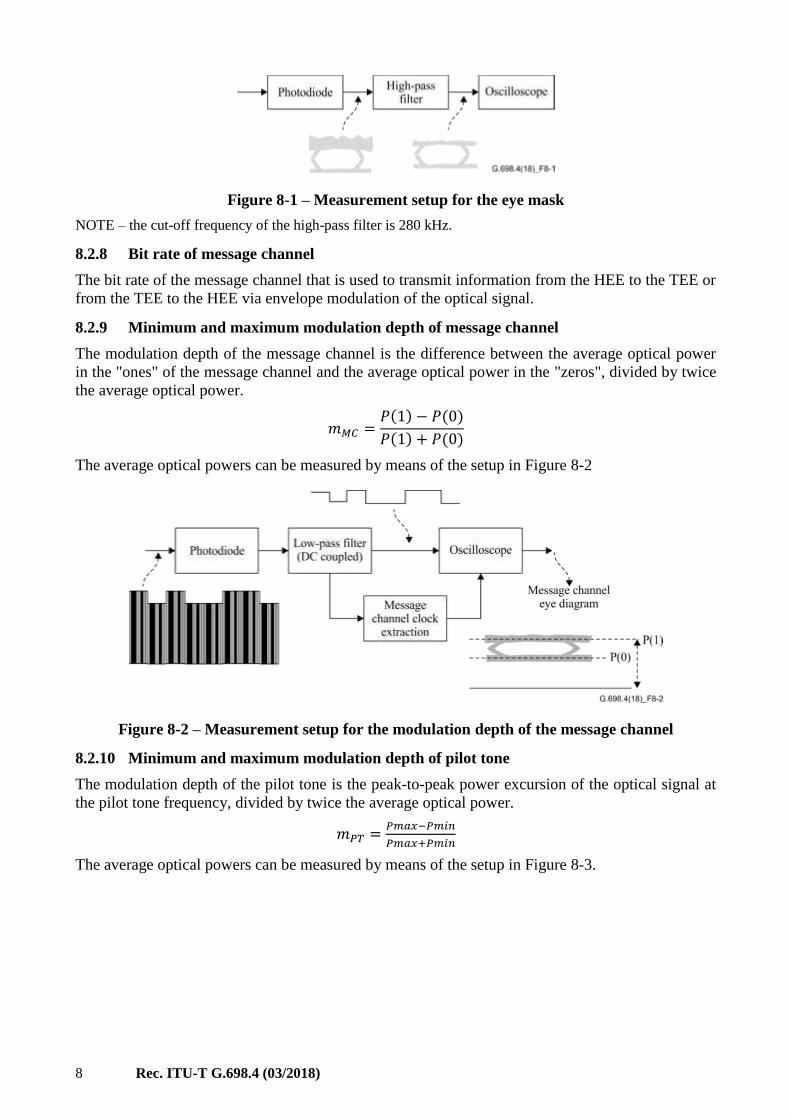
Figure 8-1 – Measurement setup for the eye mask
NOTE – the cut-off frequency of the high-pass filter is 280 kHz.
8.2.8 Bit rate of message channel
The bit rate of the message channel that is used to transmit information from the HEE to the TEE or
from the TEE to the HEE via envelope modulation of the optical signal.
8.2.9 Minimum and maximum modulation depth of message channel
The modulation depth of the message channel is the difference between the average optical power
in the "ones" of the message channel and the average optical power in the "zeros", divided by twice
the average optical power.
𝑚𝑀𝐶 =𝑃(1) − 𝑃(0)
𝑃(1) + 𝑃(0)
The average optical powers can be measured by means of the setup in Figure 8-2
Figure 8-2 – Measurement setup for the modulation depth of the message channel
8.2.10 Minimum and maximum modulation depth of pilot tone
The modulation depth of the pilot tone is the peak-to-peak power excursion of the optical signal at
the pilot tone frequency, divided by twice the average optical power.
𝑚𝑃𝑇 =𝑃𝑚𝑎𝑥−𝑃𝑚𝑖𝑛
𝑃𝑚𝑎𝑥+𝑃𝑚𝑖𝑛
The average optical powers can be measured by means of the setup in Figure 8-3.
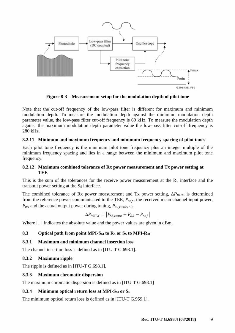
Rec. ITU-T G.698.4 (03/2018) 9
Figure 8-3 – Measurement setup for the modulation depth of pilot tone
Note that the cut-off frequency of the low-pass filter is different for maximum and minimum
modulation depth. To measure the modulation depth against the minimum modulation depth
parameter value, the low-pass filter cut-off frequency is 60 kHz. To measure the modulation depth
against the maximum modulation depth parameter value the low-pass filter cut-off frequency is
280 kHz.
8.2.11 Minimum and maximum frequency and minimum frequency spacing of pilot tones
Each pilot tone frequency is the minimum pilot tone frequency plus an integer multiple of the
minimum frequency spacing and lies in a range between the minimum and maximum pilot tone
frequency.
8.2.12 Maximum combined tolerance of Rx power measurement and Tx power setting at
TEE
This is the sum of the tolerances for the receive power measurement at the RS interface and the
transmit power setting at the SS interface.
The combined tolerance of Rx power measurement and Tx power setting, PRxTx, is determined
from the reference power communicated to the TEE, 𝑃𝑟𝑒𝑓, the received mean channel input power,
𝑃𝑅𝑆 and the actual output power during tuning, 𝑃𝑆𝑆,𝑡𝑢𝑛𝑒, as:
∆𝑃𝑅𝑋𝑇𝑋 = |𝑃𝑆𝑆,𝑡𝑢𝑛𝑒 + 𝑃𝑅𝑆 − 𝑃𝑟𝑒𝑓|
Where |. . | indicates the absolute value and the power values are given in dBm.
8.3 Optical path from point MPI-SM to RS or SS to MPI-RM
8.3.1 Maximum and minimum channel insertion loss
The channel insertion loss is defined as in [ITU-T G.698.1].
8.3.2 Maximum ripple
The ripple is defined as in [ITU-T G.698.1].
8.3.3 Maximum chromatic dispersion
The maximum chromatic dispersion is defined as in [ITU-T G.698.1]
8.3.4 Minimum optical return loss at MPI-SM or SS
The minimum optical return loss is defined as in [ITU-T G.959.1].

10 Rec. ITU-T G.698.4 (03/2018)
8.3.5 Maximum discrete reflectance between MPI-SM and RS or between SS and MPI-RM
The maximum discrete reflectance is defined as in [ITU-T G.959.1].
8.3.6 Maximum differential group delay
The maximum differential group delay is defined as in [ITU-T G.698.1]
8.3.7 Maximum inter-channel crosstalk at RS
The inter-channel crosstalk is defined as in [ITU-T G.698.1].
8.3.8 Maximum loss difference between HE-to-TE and TE-to-HE direction
This parameter defines the maximum absolute difference between the insertion loss of the optical
path from point MPI-SM to RS for the HEE to TEE wavelength of a channel and the insertion loss of
the optical path from point SS to MPI-RM for the TEE to HEE wavelength of the corresponding
channel.
8.4 Interface at point RS or MPI-RM
8.4.1 Maximum and minimum mean channel input power
The mean channel input power is defined as in [ITU-T G.959.1].
8.4.2 Maximum mean total input power
The maximum mean total input power is defined as in [ITU-T G.959.1].
8.4.3 Receiver sensitivity
The receiver sensitivity is defined as in [ITU-T G.698.1].
8.4.4 Minimum equivalent sensitivity
The minimum equivalent sensitivity is defined as in [ITU-T G.959.1].
8.4.5 Maximum optical path penalty
The maximum optical path penalty is defined as in [ITU-T G.698.1].
8.4.6 Maximum reflectance of receiver or optical network element
The maximum reflectance of receiver is defined as in [ITU-T G.698.1]
8.4.7 Minimum and maximum mean channel input power during tuning
The mean channel input power during tuning is the input power of a tuning channel at interface
MPI-RM, when the wavelength of this channel has tuned to the central frequency of the target
channel.
9 Parameter values
Table 9-1 shows parameter values from HEE to TEE for 100 GHz spaced applications

Rec. ITU-T G.698.4 (03/2018) 11
Table 9-1 – From HEE to TEE for 100 GHz spaced applications
Parameter Units AD100S-2-D2
General information
Minimum channel spacing GHz 100
Bit rate/line coding of optical tributary signals – NRZ 10G
Maximum bit-error ratio – 10−12
Fibre type – G.652
Interface at point MPI-SM
Maximum mean channel output power dBm −2
Minimum mean channel output power dBm −5
Maximum mean total output power dBm 11
Minimum central frequency THz 194.1
Maximum central frequency THz 196
Maximum spectral excursion GHz ±12.5
Minimum channel extinction ratio dB 8.2
Eye mask – NRZ 10G ratio small
Bit rate of message channel kbit/s 50
Maximum frequency tolerance of message channel ppm 100
Maximum modulation depth of message channel % 8
Minimum modulation depth of message channel % 6.5
Optical path from point MPI-SM to RS
Maximum channel insertion loss dB 14
Minimum channel insertion loss dB 8
Maximum ripple dB 2
Maximum chromatic dispersion ps/nm 400
Minimum optical return loss at MPI-SM dB 24
Maximum discrete reflectance between MPI-SM and RS dB −27
Maximum differential group delay ps 30
Maximum inter-channel crosstalk at RS dB −16
Maximum loss difference between HE-to-TE and TE-to-HE direction dB NA
Interface at point RS
Maximum mean channel input power dBm −10
Minimum mean channel input power dBm −19
Receiver sensitivity dBm −21.5
Maximum optical path penalty dB 2.5
Maximum reflectance of receiver or optical network element dB −27
Table 9-2 shows parameter values from TEE to HEE for 100 GHz spaced applications.

12 Rec. ITU-T G.698.4 (03/2018)
Table 9-2 – From TEE to HEE for 100 GHz spaced applications
Parameter Units AD100S-2-D2
General information
Minimum channel spacing GHz 100
Bit rate/line coding of optical tributary signals – NRZ 10G
Maximum bit-error ratio – 10−12
Fibre type – G.652
Interface at point SS
Maximum mean channel output power dBm +2
Minimum mean channel output power dBm −2
Minimum central frequency THz 191.5
Maximum central frequency THz 193.4
Maximum spectral excursion GHz ±12.5
Maximum laser drift GHz/10 min 1
Minimum channel extinction ratio dB 8.2
Eye mask – NRZ 10G ratio small
Bit rate of message channel kbit/s 50
Maximum frequency tolerance of message channel ppm 100
Maximum modulation depth of message channel % 8
Minimum modulation depth of message channel % 6.5
Maximum modulation depth of pilot tone during operation % 8
Minimum modulation depth of pilot tone during operation % 5
Minimum modulation depth of pilot tone during tuning % 40
Maximum frequency of pilot tone Hz 52 500
Minimum frequency of pilot tone Hz 47 500
Maximum frequency tolerance of pilot tone ppm 100
Minimum frequency spacing of pilot tones Hz 50
Maximum combined tolerance of Rx power measurement and Tx power setting at TEE ()
dB 2
Optical path from point SS to MPI-RM
Maximum channel insertion loss dB 14
Minimum channel insertion loss dB 8
Maximum ripple dB 2
Maximum chromatic dispersion ps/nm 400
Minimum optical return loss at SS dB 24
Maximum discrete reflectance between SS and MPI-RM dB −27
Maximum differential group delay ps 30
Maximum loss difference between HE-to-TE and TE-to-HE direction dB 2
Interface at point MPI-RM
Maximum mean channel input power dBm −6
Minimum mean channel input power dBm −16
Maximum mean total input power dBm 7
Minimum equivalent sensitivity dBm −18.5

Rec. ITU-T G.698.4 (03/2018) 13
Table 9-2 – From TEE to HEE for 100 GHz spaced applications
Parameter Units AD100S-2-D2
Maximum optical path penalty dB 2.5
Maximum reflectance of receiver or optical network element dB −27
Maximum mean channel input power during tuning dBm −19
Minimum mean channel input power during tuning dBm −30
Table 9-3 shows parameter values from HEE to TEE for 50 GHz spaced applications.
Table 9-3 – From HEE to TEE for 50 GHz spaced applications
Parameter Units AD50S-2-D2
General information
Minimum channel spacing GHz 50
Bit rate/line coding of optical tributary signals – NRZ 10G
Maximum bit-error ratio – 10−12
Fibre type – G.652
Interface at point MPI-SM
Maximum mean channel output power dBm −2
Minimum mean channel output power dBm −5
Maximum mean total output power dBm 14
Minimum central frequency THz 194.05
Maximum central frequency THz 196
Maximum spectral excursion GHz ±12.5
Minimum channel extinction ratio dB 8.2
Eye mask – NRZ 10G
ratio small
Bit rate of message channel kbit/s 50
Maximum frequency tolerance of message channel ppm 100
Maximum modulation depth of message channel % 8
Minimum modulation depth of message channel % 6.5
Optical path from point MPI-SM to RS
Maximum channel insertion loss dB 14
Minimum channel insertion loss dB 8
Maximum ripple dB 2
Maximum chromatic dispersion ps/nm 400
Minimum optical return loss at MPI-SM dB 24
Maximum discrete reflectance between MPI-SM and RS dB −27
Maximum differential group delay ps 30
Maximum inter-channel crosstalk at RS dB −16
Maximum loss difference between HE-to-TE and TE-to-HE direction dB 2

14 Rec. ITU-T G.698.4 (03/2018)
Table 9-3 – From HEE to TEE for 50 GHz spaced applications
Parameter Units AD50S-2-D2
Interface at point RS
Maximum mean channel input power dBm −10
Minimum mean channel input power dBm −19
Receiver sensitivity dBm −21.5
Maximum optical path penalty dB 2.5
Maximum reflectance of receiver or optical network element dB −27
Table 9-4 shows parameter values from TEE to HEE for 50 GHz spaced applications.
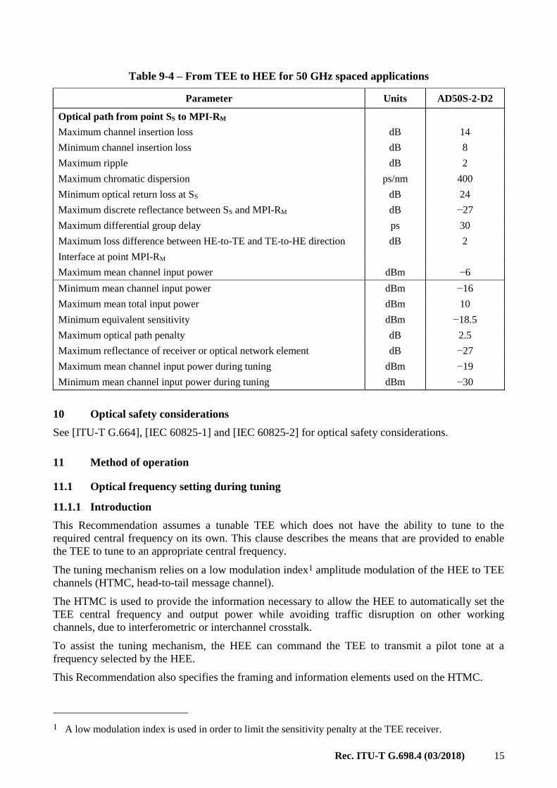
Table 9-4 – From TEE to HEE for 50 GHz spaced applications
Parameter Units AD50S-2-D2
General information
Minimum channel spacing GHz 50
Bit rate/line coding of optical tributary signals – NRZ 10G
Maximum bit-error ratio – 10−12
Fibre type – G.652
Interface at point SS
Maximum mean channel output power dBm +2
Minimum mean channel output power dBm −2
Minimum central frequency THz 191.45
Maximum central frequency THz 193.4
Maximum spectral excursion GHz ±12.5
Maximum laser drift GHz/10
min
1
Minimum channel extinction ratio dB 8.2
Eye mask – NRZ 10G
ratio small
Bit rate of message channel kbit/s 50
Maximum frequency tolerance of message channel ppm 100
Maximum modulation depth of message channel % 8
Minimum modulation depth of message channel % 6.5
Maximum modulation depth of pilot tone during operation % 8
Minimum modulation depth of pilot tone during operation % 5
Minimum modulation depth of pilot tone during tuning % 40
Maximum frequency of pilot tone Hz 52 500
Minimum frequency of pilot tone Hz 47 500
Maximum frequency tolerance of pilot tone ppm 100
Minimum frequency spacing of pilot tones Hz 50
Maximum combined tolerance of Rx power measurement and Tx power
setting at TEE (±)
dB 2
Rec. ITU-T G.698.4 (03/2018) 15
Table 9-4 – From TEE to HEE for 50 GHz spaced applications
Parameter Units AD50S-2-D2
Optical path from point SS to MPI-RM
Maximum channel insertion loss dB 14
Minimum channel insertion loss dB 8
Maximum ripple dB 2
Maximum chromatic dispersion ps/nm 400
Minimum optical return loss at SS dB 24
Maximum discrete reflectance between SS and MPI-RM dB −27
Maximum differential group delay ps 30
Maximum loss difference between HE-to-TE and TE-to-HE direction dB 2
Interface at point MPI-RM
Maximum mean channel input power dBm −6
Minimum mean channel input power dBm −16
Maximum mean total input power dBm 10
Minimum equivalent sensitivity dBm −18.5
Maximum optical path penalty dB 2.5
Maximum reflectance of receiver or optical network element dB −27
Maximum mean channel input power during tuning dBm −19
Minimum mean channel input power during tuning dBm −30
10 Optical safety considerations
See [ITU-T G.664], [IEC 60825-1] and [IEC 60825-2] for optical safety considerations.
11 Method of operation
11.1 Optical frequency setting during tuning
11.1.1 Introduction
This Recommendation assumes a tunable TEE which does not have the ability to tune to the
required central frequency on its own. This clause describes the means that are provided to enable
the TEE to tune to an appropriate central frequency.
The tuning mechanism relies on a low modulation index1 amplitude modulation of the HEE to TEE
channels (HTMC, head-to-tail message channel).
The HTMC is used to provide the information necessary to allow the HEE to automatically set the
TEE central frequency and output power while avoiding traffic disruption on other working
channels, due to interferometric or interchannel crosstalk.
To assist the tuning mechanism, the HEE can command the TEE to transmit a pilot tone at a
frequency selected by the HEE.
This Recommendation also specifies the framing and information elements used on the HTMC.
1 A low modulation index is used in order to limit the sensitivity penalty at the TEE receiver.
16 Rec. ITU-T G.698.4 (03/2018)
A low modulation index amplitude modulation of the TEE to HEE channels (THMC, tail-to-head
message channel) can be used to transmit proprietary information. This Recommendation does not
specify the structure or content of this information.
11.1.2 HTMC frame structure
The HTMC frame includes
• An 11-bit field indicating the type of message (TOM);
• A 5-bit checksum field for the TOM;
• A 24-bit field communicating the message content;
• An 8-bit checksum field for the message content.
The frame structure is illustrated in Figure 11-1.
Figure 11-1 – HTMC frame structure
The TOM checksum and the message checksum are generated based on (16,11) and (32,26)
Hamming codes, respectively.
The Hamming check bits of the TOM and message value fields are arranged as follows: the bits are
ordered from 15 for the TOM, or 31 for the value field, down to 0, to designate the position number
of each bit. Positions with power of 2 position number are occupied by Hamming check bits.
Position 0 is occupied by the parity bit. The remaining 11 positions for the TOM or 26 positions for
the value field are used for data. In the case of the message value field, two "1" bits are appended to
the 24 value bits as the two least significant data bits to complete the 26 data bits.
The Hamming check bits are calculated by bit-wise modulo-2 addition of the position numbers of
all data bits with value "1". Hamming check bit 0 is located in position 1, Hamming check bit 1 in
position 2, Hamming check bit 2 in position 4, Hamming check bit 3 in position 8 and Hamming
check bit 4 in position 16 (only for the value field). Finally, to form the parity bit, the modulo-2 sum
of all 15 or 31 Hamming codeword bits is calculated, its value is logically inverted and the result is
assigned to position 0.
Subsequently, the 16 or 32 bits are ordered such that first the 11 or 24 data bits (most significant to
least significant) are transmitted and then the 5 or 8 check bits, fixed bits and parity bit.
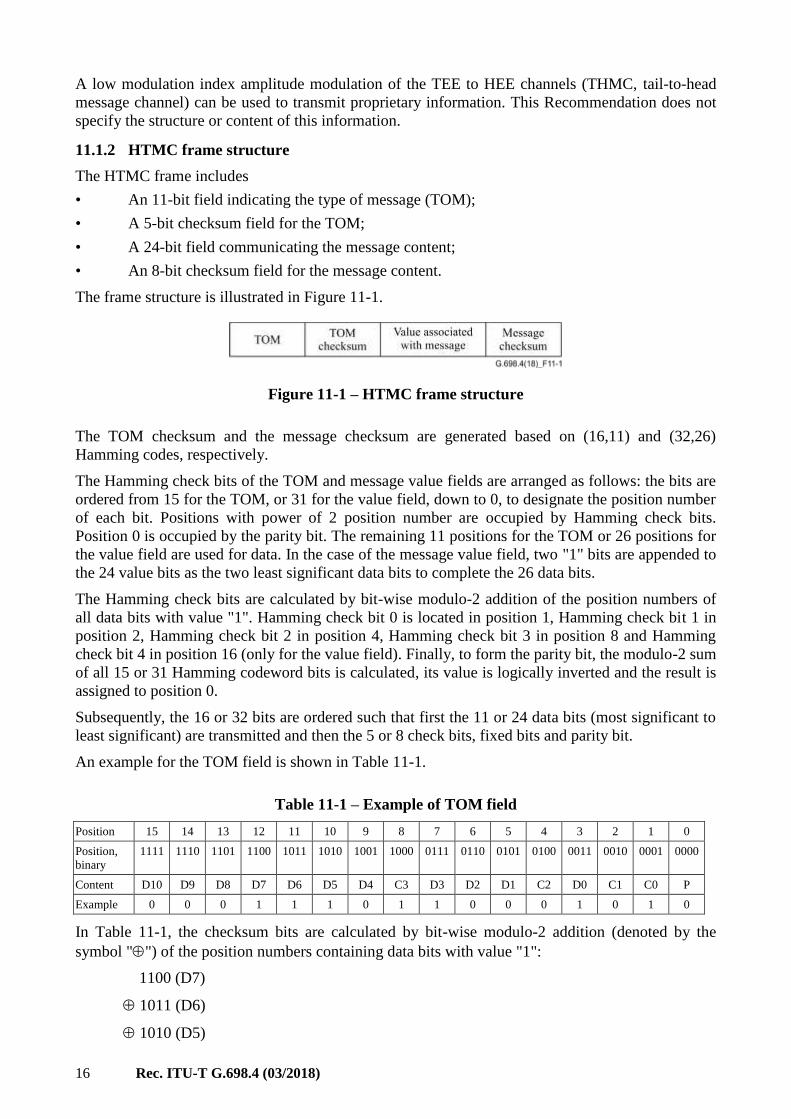
An example for the TOM field is shown in Table 11-1.
Table 11-1 – Example of TOM field
Position 15 14 13 12 11 10 9 8 7 6 5 4 3 2 1 0
Position,
binary
1111 1110 1101 1100 1011 1010 1001 1000 0111 0110 0101 0100 0011 0010 0001 0000
Content D10 D9 D8 D7 D6 D5 D4 C3 D3 D2 D1 C2 D0 C1 C0 P
Example 0 0 0 1 1 1 0 1 1 0 0 0 1 0 1 0
In Table 11-1, the checksum bits are calculated by bit-wise modulo-2 addition (denoted by the
symbol "") of the position numbers containing data bits with value "1":
1100 (D7)
1011 (D6)
1010 (D5)

Rec. ITU-T G.698.4 (03/2018) 17
0111 (D3)
0011 (D0)
____
1001 (C3 | C2 | C1 | C0)
After re-ordering, the 16 TOM and checksum bits are transmitted as
0001 1101 001 1001 0
An example for the Value field is shown in Table 11-2.
Table 11-2 – Example of Value field
Position 31 30 29 28 27 26 25 24 23 22 21 20 19 18 17 16
Position,
binary
11111 11110 11101 11100 11011 11010 11001 11000 10111 10110 10101 10100 10011 10010 10001 10000
Content D23 D22 D21 D20 D19 D18 D17 D16 D15 D14 D13 D12 D11 D10 D9 C4
Example 1 0 0 1 1 1 0 0 1 0 0 1 1 1 0 0
Position 15 14 13 12 11 10 9 8 7 6 5 4 3 2 1 0
Position,
binary
01111 01110 01101 01100 01011 01010 01001 01000 00111 00110 00101 00100 00011 00010 00001 00000
Value D8 D7 D6 D5 D4 D3 D2 C3 D1 D0 1 C2 1 C1 C0 P
Example 1 0 1 1 0 0 0 1 1 1 1 0 1 0 1 0
After re-ordering, the 32 value and checksum bits are transmitted as
1001 1100 1001 1101 0110 0011 0110 1010
The HTMC is based on continuous messaging.
Both the HTMC and the THMC are Manchester encoded as specified in clause 7.3.1.1 of
[IEEE 802.3].
The HTMC frame is detected by calculating the checksum bits from the received bit stream and
comparing them to the bits in the assumed checksum positions. If they do not match, the assumed
frame clock is shifted by one bit and a new message channel frame is received. If the expected and
the received bits in the checksum fields are identical, the frame clock is maintained. For a
successful frame lock, the checksums of 2 consecutive frames must match the calculated values.
After frame lock is achieved, the frame synchronization is monitored by comparing the checksums
of the received frames to the calculated checksums. In the locked state, observing only the
checksum of the header and requiring 6 consecutive checksum mismatches is sufficient to avoid
accidental loss-of-lock and to ensure a fast detection of actual loss-of-lock.
The TOM field allows a maximum number of 2048 different types of messages. The currently
defined messages are listed in Table 11-3.

18 Rec. ITU-T G.698.4 (03/2018)
Table 11-3 – TOM values, message types and content
TOM value Message type Message content
0 Idle
1 Frequency Nominal optical frequency
2 Tuning power Tuning power relationship to received power
3 Pilot tone frequency Frequency to be used for TEE to HEE label pilot tone
4 Start sweep
5 Turn off
6 Stop sweep
7 Change power New optical power level
8 Change frequency Change in optical frequency
9 Send traffic
10 Send pilot tone
11 Stop sending pilot tone
Central frequencies are encoded in the Message Content field as a 2's complement signed integer, as
the offset from 193.1 THz with a resolution of 10 MHz2.
For example, a wavelength value of 1260 nm is first converted in frequency units, namely
237.93052 THz, with an accuracy of 10 MHz. This value is 44.83052 THz (4483052 × 10 MHz)
above 193.1 THz, corresponding to 0x4467EC in hexadecimal notation. As a second example,
1560 nm is equivalent to 192.17465 THz, which is 0.92535 THz (92535 × 10 MHz) below
193.1 THz and is encoded as 0xFE9689.
TEE transmitter power is encoded as a 2's complement signed integer representing power values
from −30 to 30 dBm with 0.1 dB resolution.
For example, +3 dBm is encoded as +30 which is 0x1E in hexadecimal while −3 dBm is encoded as
0xFFFFE2.
Pilot tone frequencies are encoded in the Message Content field as unsigned integers representing
tone frequency values, with 10 Hz resolution.
For example, 50 kHz is encoded as 5000, which is 0x001388 in hexadecimal and 47.5 kHz is 4750,
which is encoded as 0x00128E.
Idle messages (TOM=0) are transmitted, when the control of the tail-end equipment does not
require the transmission of any other message type over the HTMC. For idle messages, the message
content field is not specified, but it can be used to transmit proprietary information between the
head-end and the tail-end. This Recommendation does not specify the structure or content of this
information.
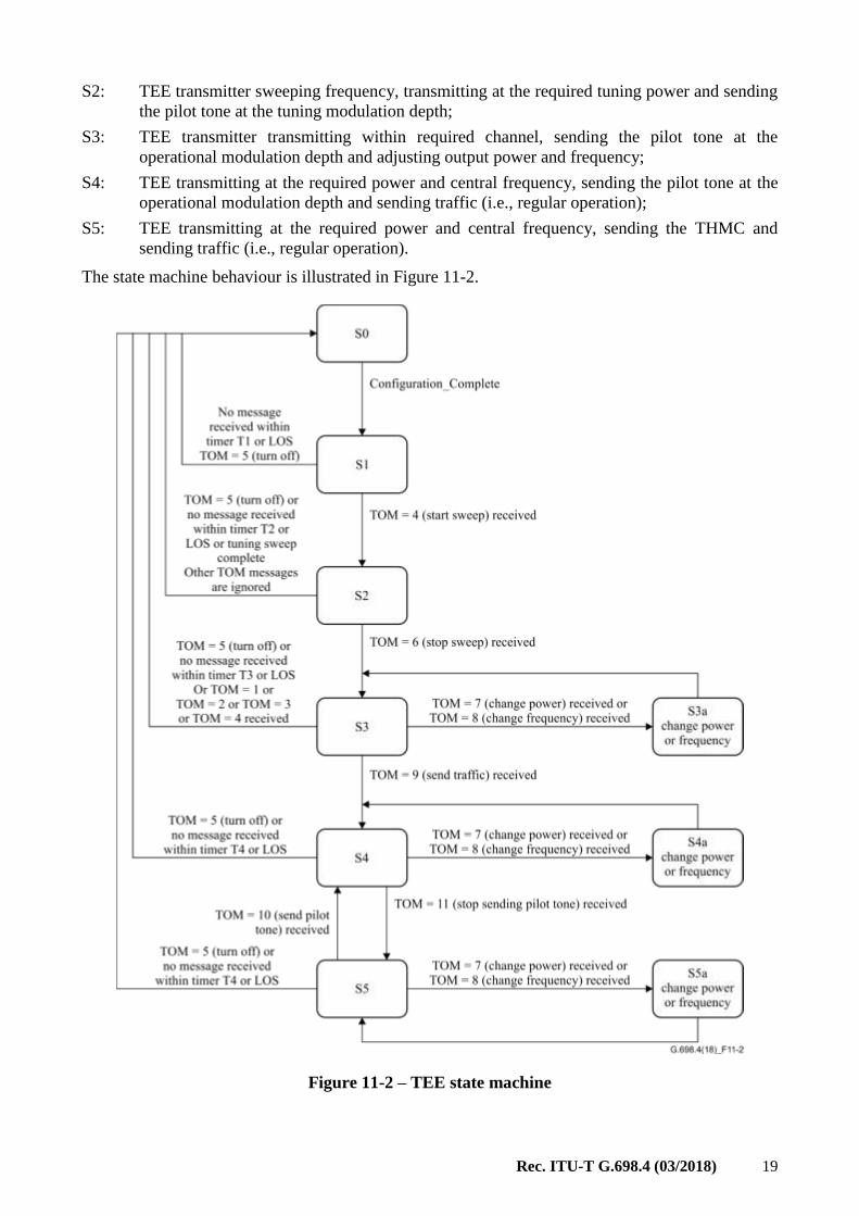
11.1.3 TEE state machine
The behaviour of the TEE is defined as a state machine operating on the values of the TOM field in
the HTMC.
The state machine has six states:
S0: TEE transmitter switched off in standby mode;
S1: TEE transmitter switched off but ready to start the tuning procedure;
2 This makes it possible to encode frequencies with the granularity of 6.25 GHz.
Rec. ITU-T G.698.4 (03/2018) 19
S2: TEE transmitter sweeping frequency, transmitting at the required tuning power and sending
the pilot tone at the tuning modulation depth;
S3: TEE transmitter transmitting within required channel, sending the pilot tone at the
operational modulation depth and adjusting output power and frequency;
S4: TEE transmitting at the required power and central frequency, sending the pilot tone at the
operational modulation depth and sending traffic (i.e., regular operation);
S5: TEE transmitting at the required power and central frequency, sending the THMC and
sending traffic (i.e., regular operation).
The state machine behaviour is illustrated in Figure 11-2.
Figure 11-2 – TEE state machine

20 Rec. ITU-T G.698.4 (03/2018)
Configuration_Complete becomes true after at least one of each of the messages TOM=1, TOM=2
and TOM=3 have been received. Configuration_Complete is initialised as false when state S0 is re-
entered.
Timers T0 – T4 are used to avoid the TEE operating for an excessive amount of time without
receiving control messages from the HEE. The timers T0-T4 are reset, when the TEE enters a
respective state according to Figure 11-2 (S1 for T1, S2 for T2, S3 for T3, S4 or S5 for T4) or
receives a message with any message type while in the respective state. The timer is reset to the
start value of 1 minute for all timers and counts down with time.
An example sequence of messages sent from the HEE to the TEE might be: TOM=0 (Idle) TOM=0 (Idle) TOM=0 (Idle) TOM=1 (Frequency) TOM=2 (Tuning power) TOM=3 (Pilot tone frequency) TOM=4 (Start sweep) TOM=0 (Idle) TOM=0 (Idle) TOM=0 (Idle) TOM=0 (Idle) ... TOM=0 (Idle) TOM=6 (Stop sweep) TOM=0 (Idle) TOM=0 (Idle) TOM=8 (Change frequency) TOM=0 (Idle) TOM=0 (Idle) TOM=8 (Change frequency) TOM=0 (Idle) TOM=0 (Idle) TOM=7 (Change power) TOM=0 (Idle) TOM=0 (Idle) TOM=9 (Send traffic) TOM=0(Idle) TOM=0(Idle) TOM=11 (Stop sending pilot tone) TOM=0 (Idle) TOM=0 (Idle) TOM=10 (Send pilot tone) TOM=0 (Idle) TOM=0 (Idle) TOM=8 (Change frequency) TOM=0 (Idle) TOM=0 (Idle) TOM=7 (Change power) TOM=0 (Idle) TOM=0 (Idle) TOM=0 (Idle) TOM=0 (Idle) TOM=11 (Stop sending pilot tone) TOM=0 (Idle) TOM=0 (Idle) TOM=0 (Idle) ...
When there is no active TEE connected to a particular RS/SS port, the message sequence: TOM = 1,
2, 3, 4 is sent periodically to allow a newly connected TEE to start the tuning process.

Rec. ITU-T G.698.4 (03/2018) 21
11.2 Output power setting during tuning
To reduce the crosstalk on working channels during the TEE tuning process, the TEE transmitter
output power is reduced with respect to normal operation.
The TEE output power during tuning is determined from the estimated optical path loss between the
TEE and the HEE, which is derived from the mean channel input power at point RS.
A reference power value, depending on the application code, is communicated from the HEE to the
TEE via the HTMC. This reference power level is calculated from the physical layer parameters
(Table 8-1) for the application code as:
𝑃𝑟𝑒𝑓 =(𝑃𝑅𝑀,𝑡𝑢𝑛𝑒,𝑚𝑎𝑥+𝑃𝑅𝑀,𝑡𝑢𝑛𝑒,𝑚𝑖𝑛)
2+
(𝑃𝑆𝑀,𝑚𝑎𝑥+𝑃𝑆𝑀,𝑚𝑖𝑛)
2.
In this Equation, the parameters have the following meaning and are defined in clause 8.
PSM,min : Minimum mean channel output power at MPI-SM (in dBm)
PSM,max : Maximum mean channel output power at MPI-SM (in dBm)
PRM,tune,min : Minimum mean channel input power during tuning at MPI-RM (in dBm)
PRM,tune,max : Maximum mean channel input power during tuning at MPI-RM (in dBm)
The TEE output power during tuning, 𝑃𝑆𝑆,𝑡𝑢𝑛𝑒, is set, based on the communicated reference power,
𝑃𝑟𝑒𝑓 and the measured mean channel input power, 𝑃𝑅𝑆:
𝑃𝑆𝑆,𝑡𝑢𝑛𝑒 = 𝑃𝑟𝑒𝑓 − 𝑃𝑅𝑆.
(All values in dBm).
To maintain the estimated and measured loss and power values close to the actual values, the
maximum combined tolerance of Rx power measurement and Tx power setting at the TEE
(PRXTX, clause 8.2.12) is specified, as well as the maximum loss difference of a channel between
HEE to TEE and TEE to HEE directions (L, clause 8.3.8).

22 Rec. ITU-T G.698.4 (03/2018)
Appendix I
Output power setting during tuning
(This appendix does not form an integral part of this Recommendation.)
In order to set the output power during tuning (as in clause 11.2), the application code parameters
are chosen to meet the following relation:
PRM,tune,max – PRM,tune,min (PSM,max – PSM,min) + 2L + 2PRXTX
Where:
• PRM,tune,max is the maximum mean channel input power during tuning at MPI-RM (in dBm),
as defined in clause 8.4.8;
• PRM,tune,min is the minimum mean channel input power during tuning at MPI-RM (in dBm),
as defined in clause 8.4.8;
• PSM,max is the maximum mean channel output power at MPI-SM (in dBm), as defined in
clause 8.2.1;
• PSM,min is the minimum mean channel output power at MPI-SM (in dBm), as defined in
clause 8.2.1;
• L is the maximum loss difference of a channel between HE-to-TE and TE-to-HE
directions, as defined in clause 8.3.8;
• PRXTX is the maximum combined tolerance of Rx power measurement and Tx power
setting at the TEE.

Printed in Switzerland Geneva, 2018
SERIES OF ITU-T RECOMMENDATIONS
Series A Organization of the work of ITU-T
Series D Tariff and accounting principles and international telecommunication/ICT economic and
policy issues
Series E Overall network operation, telephone service, service operation and human factors
Series F Non-telephone telecommunication services
Series G Transmission systems and media, digital systems and networks
Series H Audiovisual and multimedia systems
Series I Integrated services digital network
Series J Cable networks and transmission of television, sound programme and other multimedia
signals
Series K Protection against interference
Series L Environment and ICTs, climate change, e-waste, energy efficiency; construction, installation
and protection of cables and other elements of outside plant
Series M Telecommunication management, including TMN and network maintenance
Series N Maintenance: international sound programme and television transmission circuits
Series O Specifications of measuring equipment
Series P Telephone transmission quality, telephone installations, local line networks
Series Q Switching and signalling, and associated measurements and tests
Series R Telegraph transmission
Series S Telegraph services terminal equipment
Series T Terminals for telematic services
Series U Telegraph switching
Series V Data communication over the telephone network
Series X Data networks, open system communications and security
Series Y Global information infrastructure, Internet protocol aspects, next-generation networks,
Internet of Things and smart cities
Series Z Languages and general software aspects for telecommunication systems