Embed Size (px)
Citation preview

I n t e r n a t i o n a l T e l e c o m m u n i c a t i o n U n i o n
ITU-T K.104 TELECOMMUNICATION STANDARDIZATION SECTOR OF ITU
(03/2015)
SERIES K: PROTECTION AGAINST INTERFERENCE
Method for identifying the transfer potential of the earth potential rise from high or medium voltage networks to the earthing system or neutral of low voltage networks
Recommendation ITU-T K.104


Rec. ITU-T K.104 (03/2015) i
Recommendation ITU-T K.104
Method for identifying the transfer potential of the earth potential rise from high
or medium voltage networks to the earthing system or neutral of low voltage
networks
Summary
In the case of earth faults in high or medium voltage AC networks, significant earth potential rise
(EPR) can occur in the earthing structure where the current is discharged to the earth; typically this is
in the earthing grid of the substation involved in the fault. When the earthing grid is connected
metallically to long conductors such as earth wires, neutral conductors, counterpoises, cable sheaths,
pipes and rails, the EPR can be transferred over far distances well beyond the zone of influence.
Recommendation ITU-T K.104 describes the mechanism of potential transfer to a customer's premise
with a special view of the transfer through the neutral conductor of a low-voltage network and the
sheath of a telecommunication cable. Calculation techniques are given for the determination of the
magnitude of EPR and transferred potential. Mitigation techniques for preventing the transfer of EPR
are proposed. Different isolation techniques are proposed as possible mitigation techniques applicable
in a telecommunication plant.
History
Edition Recommendation Approval Study Group Unique ID*
1.0 ITU-T K.104 2015-03-01 5 11.1002/1000/12424
Keywords
Double earth fault, earth electrode effect, earth fault, earthing, earth potential rise, EPR, impedance to
earth, metallic transfer, multi earthed, screening factor, transferred potential.
____________________ * To access the Recommendation, type the URL http://handle.itu.int/ in the address field of your web
browser, followed by the Recommendation's unique ID. For example, http://handle.itu.int/11.1002/1000/11830-en.

ii Rec. ITU-T K.104 (03/2015)
FOREWORD
The International Telecommunication Union (ITU) is the United Nations specialized agency in the field of
telecommunications, information and communication technologies (ICTs). The ITU Telecommunication
Standardization Sector (ITU-T) is a permanent organ of ITU. ITU-T is responsible for studying technical,
operating and tariff questions and issuing Recommendations on them with a view to standardizing
telecommunications on a worldwide basis.
The World Telecommunication Standardization Assembly (WTSA), which meets every four years, establishes
the topics for study by the ITU-T study groups which, in turn, produce Recommendations on these topics.
The approval of ITU-T Recommendations is covered by the procedure laid down in WTSA Resolution 1.
In some areas of information technology which fall within ITU-T's purview, the necessary standards are
prepared on a collaborative basis with ISO and IEC.
NOTE
In this Recommendation, the expression "Administration" is used for conciseness to indicate both a
telecommunication administration and a recognized operating agency.
Compliance with this Recommendation is voluntary. However, the Recommendation may contain certain
mandatory provisions (to ensure, e.g., interoperability or applicability) and compliance with the
Recommendation is achieved when all of these mandatory provisions are met. The words "shall" or some other
obligatory language such as "must" and the negative equivalents are used to express requirements. The use of
such words does not suggest that compliance with the Recommendation is required of any party.
INTELLECTUAL PROPERTY RIGHTS
ITU draws attention to the possibility that the practice or implementation of this Recommendation may involve
the use of a claimed Intellectual Property Right. ITU takes no position concerning the evidence, validity or
applicability of claimed Intellectual Property Rights, whether asserted by ITU members or others outside of
the Recommendation development process.
As of the date of approval of this Recommendation, ITU had not received notice of intellectual property,
protected by patents, which may be required to implement this Recommendation. However, implementers are
cautioned that this may not represent the latest information and are therefore strongly urged to consult the TSB
patent database at http://www.itu.int/ITU-T/ipr/.
ITU 2015
All rights reserved. No part of this publication may be reproduced, by any means whatsoever, without the prior
written permission of ITU.

Rec. ITU-T K.104 (03/2015) iii
Table of Contents
Page
1 Scope ............................................................................................................................. 1
2 References ..................................................................................................................... 1
3 Definitions .................................................................................................................... 2
3.1 Terms defined elsewhere ................................................................................ 2
3.2 Terms defined in this Recommendation ......................................................... 5
4 Abbreviations and acronyms ........................................................................................ 5
5 Conventions .................................................................................................................. 6
6 Earth potential rise in electric power systems .............................................................. 6
7 Metallic transfer of EPR ............................................................................................... 7
7.1 Description of metallic transfer and influences on telecommunications ........ 7
7.2 Calculation of metallic transfer ...................................................................... 7
7.3 Transfer of the EPR by power lines ............................................................... 10
7.4 Transfer of the EPR due to an HV fault ......................................................... 10
7.5 Transfer of the EPR due to an MV fault and influence on customer
premises .......................................................................................................... 13
8 Mitigation techniques ................................................................................................... 15
8.1 Protecting telecommunication lines serving LV installations (MV faults) .... 15
Annex A – Techniques for calculating the EPR in electric power systems ............................. 22
A.1 Network parameters affecting the EPR .......................................................... 22
A.2 Techniques for calculating the EPR ............................................................... 25
Appendix I – Calculation of fault current distribution ............................................................. 33
Appendix II – Through tower earthing during power line faults ............................................. 38
II.1 Equivalent circuit of the earth wire with earth return ..................................... 38
II.2 Solution of the circuit ..................................................................................... 39
II.3 Example of application ................................................................................... 40
Appendix III – Impedance to earth of MV/LV transformer stations ....................................... 43
III.1 Types of measured transformer stations ......................................................... 43
III.2 Measurement method ..................................................................................... 43
III.3 Results of the measurements .......................................................................... 46
III.4 Conclusions .................................................................................................... 46
Appendix IV – Transferred voltage and current by means of LV neutral conductors ............. 50
IV.1 System modelling, options and parameters .................................................... 50
IV.2 Feeding of the neutral-to-earth loop ............................................................... 52
IV.3 Voltage and current profiles vs. length of the neutral .................................... 52
Appendix V – Input impedance of the LV neutral-to-earth loop ............................................. 60
VI.1 Problem identification .................................................................................... 63

iv Rec. ITU-T K.104 (03/2015)
Page
VI.2 Study of the relative importance of the network parameters and
conditions ....................................................................................................... 64
VI.3 Main conclusions ............................................................................................ 65
Appendix VII – Screening factor of a power cable with an imperfectly earthed sheath ......... 68
VII.1 Criterion for long cables ................................................................................. 68
VII.2 Short (finite length) cable sheaths with continuous earthing ......................... 68
VII.3 Screening factor of a power cable with an insulating cover ........................... 68
VII.4 Screening factors for non-uniform lines ......................................................... 70
Appendix VIII – Screening factors of telecommunication cables with imperfectly earthed
sheaths ........................................................................................................................... 71
VIII.1 Telecommunication cables affected by longitudinal induction ...................... 71
VIII.2 Telecommunication cables affected by EPR .................................................. 73
Bibliography............................................................................................................................. 75

Rec. ITU-T K.104 (03/2015) 1
Recommendation ITU-T K.104
Method for identifying the transfer potential of the earth potential rise from
high or medium voltage networks to the earthing system or neutral of low
voltage networks
1 Scope
This Recommendation specifically addresses the magnitude of transferred earth potential rise (EPR)
to telecommunication systems due to faults in AC power systems, and how to mitigate these effects.
The intent of this Recommendation is to provide a good source of information for engineers who need
guidance on how to assess the magnitude of transferred EPR to telecommunication systems due to
faults in AC power systems, and how they can mitigate such effects. The main objective of this
Recommendation is to identify situations where the transfer of EPR to telecommunication systems
may cause problems.
2 References
The following ITU-T Recommendations and other references contain provisions which, through
reference in this text, constitute provisions of this Recommendation. At the time of publication, the
editions indicated were valid. All Recommendations and other references are subject to revision;
users of this Recommendation are therefore encouraged to investigate the possibility of applying the
most recent edition of the Recommendations and other references listed below. A list of the currently
valid ITU-T Recommendations is regularly published. The reference to a document within this
Recommendation does not give it, as a stand-alone document, the status of a Recommendation.
[ITU-T K.21] Recommendation ITU-T K.21 (2003), Resistibility of telecommunication
equipment installed in customer premises to overvoltages and
overcurrents.
[ITU-T K.26] Recommendation ITU-T K.26 (2008), Protection of telecommunication
lines against harmful effects from electric power and electrified railway
lines.
[ITU-T K.35] Recommendation ITU-T K.35 (1996), Bonding configurations and
earthing at remote electronic sites.
[ITU-T K.45] Recommendation ITU-T K.45 (2011), Resistibility of telecommunication
equipment installed in the access and trunk networks to overvoltages and
overcurrents.
[ITU-T K.57] Recommendation ITU-T K.57 (2003), Protection measures for radio base
stations sited on power line towers.
[ITU-T K.66] Recommendation ITU-T K.66 (2011), Protection of customer premises
from overvoltages.
[ITU-T K.68] Recommendation ITU-T K.68 (2008), Operator responsibilities in the
management of electromagnetic interference by power systems on
telecommunication systems.
[EN 50122-1] CENELEC EN 50122-1 (2011), Railway applications – Fixed
installations – Electrical safety, earthing and the return circuit – Part 1:
Protective provisions against electric shock.
[EN 50310] CENELEC EN 50310 (2006), Application of equipotential bonding and
earthing in buildings with information technology equipment.

2 Rec. ITU-T K.104 (03/2015)
[EN 50522] CENELEC EN 50522 (2010), Earthing of power installations exceeding 1
kV a.c.
[IEC 61936-1] IEC 61936-1 (2010), Power installations exceeding 1 kV a.c. – Part 1:
Common rules.
[IEEE 80-2000] IEEE Std 80-2000 (2000), IEEE Guide for Safety in AC Substation
Grounding.
[IEEE 81-2012] IEEE Std 81-2012 (2012), IEEE Guide for Measuring Earth Resistivity,
Ground Impedance, and Earth Surface Potentials of a Grounding System.
3 Definitions
3.1 Terms defined elsewhere
This Recommendation uses the following terms defined in [EN 50522], [IEC 61936-1] and
[b-Electropedia]:
3.1.1 cable with earth electrode effect: Cable whose sheaths, screens or armouring have the same
effect as a strip earth electrode.
3.1.2 circulating transformer neutral current: Portion of fault current which flows back to the
transformer neutral point via the metallic parts and/or the earthing system without ever discharging
into soil.
3.1.3 (local) earth [b-Electropedia]: (definition 195-01-03, modified) Part of the earth, which is in
electric contact with an earth electrode and the electric potential of which is not necessarily equal to
zero.
NOTE – The conductive mass of the earth, whose electric potential at any point is conventionally taken as
equal to zero.
3.1.4 earthing conductor [b-Electropedia]: (definition 195-02-03) Conductor which provides a
conductive path, or part of the conductive path, between a given point in a system or in an installation
or in equipment and an earth electrode.
NOTE – Where the connection between part of the installation and the earth electrode is made via a
disconnecting link, disconnecting switch, surge arrester counter, surge arrester control gap etc., then only that
part of the connection permanently attached to the earth electrode is an earthing conductor.
3.1.5 earth electrode [b-Electropedia]: (definition 195-02-01) Conductive part, which may be
embedded in a specific conductive medium, e.g., in concrete or coke, in electric contact with the
earth.
3.1.6 earth fault [b-Electropedia]: (definition 151-03-40) Fault caused by a conductor being
connected to earth or by the insulation resistance to earth becoming less than a specified value.
3.1.7 earth fault current, IF: Current which flows from the main circuit to earth or earthed parts
at the fault location.
NOTE 1 – For single earth faults, this is:
– in systems with isolated neutral, the capacitive earth fault current;
– in systems with high resistive earthing, the RC composed earth fault current;
– in systems with resonant earthing, the earth fault residual current;
– in systems with solid or low impedance neutral earthing, the line-to-earth short-circuit current.
NOTE 2 – Further earth fault current may result from double earth fault and line to line to earth.
3.1.8 earth potential rise, EPR UE: Voltage between an earthing system and reference earth.
3.1.9 electric resistivity of soil, ρE: Resistivity of a typical sample of soil.

Rec. ITU-T K.104 (03/2015) 3
3.1.10 earthing system [b-Electropedia]: (definition 604-04-02) Arrangement of connections and
devices necessary to earth equipment or a system separately or jointly.
3.1.11 foundation earth electrode [b-Electropedia]: (definition 826-13-08, modified) Conductive
structural embedded in concrete which is in conductive contact with the earth via a large surface.
3.1.12 global earthing system: Equivalent earthing system created by the interconnection of local
earthing systems that ensures, by the proximity of the earthing systems, that there are no dangerous
touch voltages.
NOTE 1 – Such systems permit the division of the earth fault current in a way that results in a reduction of the
earth potential rise at the local earthing system. Such a system could be said to form a quasi equipotential
surface.
NOTE 2 – The existence of a global earthing system may be determined by sample measurements or
calculation for typical systems. Typical examples of global earthing systems are in city centres; urban or
industrial areas with distributed low- and high-voltage earthing.
3.1.13 high voltage (HV) [b-Electropedia]: (definition 151-15-05) Voltage having a value above a
conventionally adopted limit.
NOTE 1 – An example is the set of upper voltage values used in bulk power systems.
NOTE 2 – In the case of a three-phase system the voltage refers to the line-to-line voltage.
3.1.14 impedance to earth, Ze: Impedance at a given frequency between a specified point in a
system or in an installation or in equipment and reference earth.
NOTE – The impedance to earth is determined by the directly connected earth electrodes and also by connected
overhead earth wires and wires buried in earth of overhead lines, by connected cables with earth electrode
effect and by other earthing systems which are conductively connected to the relevant earthing system by
conductive cable sheaths, shields, PEN conductors or in another way.
3.1.15 low voltage (LV) [b-Electropedia]: (definition 151-15-03) Voltage having a value below a
conventionally adopted limit.
NOTE 1 – For the distribution of AC electric power, the upper limit is generally accepted to be 1000 V.
NOTE 2 – In the case of a three-phase system the voltage refers to the line-to-line voltage.
3.1.16 medium voltage (MV) [b-Electropedia]: (definition 601-01-281) (not used in the UK or in
Australia) Any set of voltage levels lying between low and high voltage.
NOTE 1 – The boundaries between medium and high voltage levels overlap and depend on local circumstances
and history or common usage. Nevertheless, the band 30 kV to 100 kV frequently contains the accepted
boundary.
NOTE 2 – Medium voltage is not a standardized term. It is specified as a system, voltage class by
IEEE [b-Terms].
NOTE 3 – The preferred nominal (line-to-line) medium voltages in North America are: 4.16 kV, 12.46 kV,
13.8 kV, 34.5 kV and 69 kV [b-Terms]. Typical MV system voltages for public distribution: in Europe 10 kV
(mainly underground) 20 kV and 35 kV (mainly overhead) [b-Cahier173], in Japan 6.6 kV.
3.1.17 multi earthed HV neutral conductor: Neutral conductor of a distribution line connected to
the earthing system of the source transformer and regularly earthed.
3.1.18 nominal voltage of a system [b-Electropedia]: (definition 601-01-21) Suitable approximate
value of voltage used to designate or identify a system.
3.1.19 PEN conductor [b-Electropedia]: (definition 826-13-25) Conductor combining the functions
of both protective earthing conductor and neutral conductor.
3.1.20 potential: Voltage between an observation point and reference earth.
3.1.21 potential grading earth electrode: Conductor which due to shape and arrangement is
principally used for potential grading rather than for establishing a certain resistance to earth.

4 Rec. ITU-T K.104 (03/2015)
3.1.22 power station [b-Electropedia]: (definition 602-01-01) Installation whose purpose is to
generate electricity and which includes civil engineering works, energy conversion equipment and all
necessary ancillary equipment.
3.1.23 protective earthing conductor: Protective conductor for ensuring equipotential bonding.
3.1.24 reference earth [b-Electropedia]: (definition 195-01-01, modified): (remote earth) Part of
the earth considered as conductive, the electric potential of which is conventionally taken as zero,
being outside the zone of influence of the relevant earthing arrangement.
NOTE – The term "earth" means the planet and all its physical matter.
3.1.25 resistance to earth, Re: Real part of the impedance to earth.
3.1.26 screening factor ks (also called reduction factor, r: Factor ks of a three phase line is the
ratio of the current flowing in the earth, IE over the sum of the zero sequence currents in the phase
conductors of the main circuit (ks = IE /3I0) at a point remote from the short-circuit location and the
earthing system of an installation, (also referred to as reduction factor, r [EN 50522]).
3.1.27 solidly earthed neutral system [b-Electropedia]: (definition 601-02-25) System whose
neutral point(s) is(are) earthed directly.
3.1.28 stress voltage: Voltage appearing during earth fault conditions between an earthed part or
enclosure of equipment or device and any other of its parts and which could affect its normal operation
or safety.
3.1.29 structural earth electrode: Metal part, which is in conductive contact with the earth or with
water directly or via concrete, whose original purpose is not earthing, but which fulfils all
requirements of an earth electrode without impairment of the original purpose.
NOTE – Examples of structural earth electrodes are: pipelines, sheet piling, concrete reinforcement bars in
foundations and the steel structure of buildings, etc.
3.1.30 substation [b-Electropedia]: (definition 605-01-01) Part of a power system, concentrated in
a given place, including mainly the terminations of transmission or distribution lines, switchgear and
housing which may also include transformers. It generally includes facilities necessary for system
security and control (e.g., protective devices).
NOTE – According to the nature of the system within which the substation is included, a prefix may qualify
the substation type. Examples include: transmission substation (of a transmission system), distribution
substation, 400 kV substation, 20 kV substation.
3.1.31 system with isolated neutral [b-Electropedia]: (definition 601-02-24, modified) System in
which the neutrals of transformers and generators are not intentionally connected to earth, except for
high impedance connections for signalling, measuring or protection purposes.
3.1.32 system with low-impedance neutral earthing [b-Electropedia]: (definitions 601-02-25,
601-02-26) System in which at least one neutral of a transformer, earthing transformer or generator
is earthed via an impedance designed such that due to an earth fault at any location the magnitude of
the fault current leads to a reliable automatic tripping due to the magnitude of the fault current.
3.1.33 system with resonant earthing: System in which at least one neutral of a transformer or
earthing transformer is earthed via an arc suppression coil and the combined inductance of all arc
suppression coils is essentially tuned to the earth capacitance of the system for the operating
frequency.
NOTE 1 – In case of no self-extinguishing arc fault there are two different operation methods used:
– automatic disconnection;
– continuous operation during fault localization process.
In order to facilitate the fault localization and operation there are different supporting procedures:
– short term earthing for detection;

Rec. ITU-T K.104 (03/2015) 5
– short term earthing for tripping;
– operation measures, such as disconnection of coupled bus bars;
– phase earthing.
NOTE 2 – Arc suppression coils may have high ohmic resistors in parallel to facilitate fault detection.
3.1.34 transferred earth potential: Potential rise of an earthing system caused by a current to earth
transferred by means of a connected conductor (for example a metallic cable sheath, PEN conductor,
pipeline, rail) into areas with low or no potential rise relative to reference earth, resulting in a potential
difference occurring between the conductor and its surroundings.
NOTE – The definition also applies where a conductor, which is connected to reference earth, leads into the
area of the potential rise.
3.2 Terms defined in this Recommendation
This Recommendation defines the following terms:
3.2.1 effective station impedance to earth, Ze,st: Is composed of the resistance to earth, Re of the
earthing grid and the parallel equivalent of the impedance to earth of the connected passive (not
in-feeding on the fault) lines with earth electrode effect.
3.2.2 equivalent current to earth: Is the sum of the earth current induced by the zero sequence
component of fault current of the in-feeding power lines. It can be expressed as sum of the products
of the screening factor ki and the zero sequence current 3I0,i relevant to the i-th line.
3.2.3 equivalent impedance to earth: Is the parallel equivalent of the resistance Re to earth of the
mesh earth electrode and input (earth wire/tower footing chain, or cable sheath) impedance to earth
of the connected passive lines with earth electrode effect and impedance to earth of the return
conductors of the in-feeding lines having earth electrode effect.
4 Abbreviations and acronyms
This Recommendation uses the following abbreviations and acronyms:
ADSL Asymmetric Digital Subscriber Line
CPU Combination Protection Unit
EMF Electromotive Force
EPR Earth Potential Rise
GMR Geometric Mean Radius
HV High Voltage
LV Low Voltage
MET Main Earth Terminal
MV Medium Voltage
OHL Overhead (power) Line
PEN Protective Earth and Neutral
PSTN Public Service Telecommunication Network
SPD Surge Protective Device
ZOI Zone of Influence

6 Rec. ITU-T K.104 (03/2015)
5 Conventions
None.
6 Earth potential rise in electric power systems
Earth potential rise (EPR), occurring due to earth faults in electric power systems, can cause damage
to telecommunication plants and endanger people working in the plants, when EPR is transferred by
metallic transfer to the telecommunication plant. The International Electrotechnical Commission
(IEC) defines EPR as the voltage between an earthing system and the reference earth [EN 50522],
[IEC 61936-1]. The "reference earth" (remote earth) is a point distant enough from the earthing
system that the electric potential at this point can be conveniently taken as zero. Roughly speaking,
EPR is the product of current to the earth and impedance to earth of the installation. This EPR can be
transferred totally or partially by means of a connected conductor (e.g., metallic cable sheath,
protective earth and neutral (PEN) conductor, pipeline, rail) into areas with low or no potential rise
relative to reference earth, resulting in a potential difference occurring between the conductor and its
surroundings, or conversely (see Note in clause 3.1.34), by a conductor which is connected to
reference earth and leads into the area of the potential rise. This situation occurs often in
telecommunication lines. In any case, the EPR is the starting point when considering the metallic
transfer of EPR.
The key network parameters affecting EPR are (see clause A.1):
1) The magnitude of the short-circuit current, i.e., the phase-to-earth fault current for networks
with solidly-earthed neutral (high voltage (HV) systems and medium voltage (MV)
distribution networks in North America) and double earth fault current on isolated or resonant
earthing neutral MV systems.
The current 3I0 in-feeding by the line(s) to the fault is not causing the EPR, but the fraction
of the current which returns through the earth and thus on the effective station impedance to
earth. In the case of long homogenous lines, the effective station earth current can be
expressed by the screening factor ks of the return conductor with the following simple
equation: Ie,st = ks 3I0. In the case of a more complex in-feeding line arrangement (short, or
non-homogenous or multiple coupled line system), the current distribution for the in-feeding
line system should be determined by an appropriate multi-conductor line solution technique,
thus obtaining the station earth current causing the EPR.
2) The station impedance to earth Ze,st of a substation results from the contribution of the grid
resistance, Re in parallel with the outgoing lines carrying passive conductors connected to the
grid with earth electrode effect characterized by Ze.pl.
It should be noted that the station impedance to earth Ze,st of an MV/low voltage (LV)
transformer station can be highly affected (decreased) by the earth electrode effect of the
outgoing LV neutral conductors. As an example, assuming a small MV/LV substation grid
with resistance to earth of Re = 5 and five LV line neutral conductors with input impedance
of 0.9, phase 14o each (see Appendix V), the parallel-connected resultant impedance to
earth is: Ze,st= 0.174 phase 13.5o. (See the impedance to earth values given in Appendix III.)
Note in the case of a large substation (in hundred meter order of size) there is significant voltage drop
from the point of current injection (e.g., fault) to the edge of the grid. For example, the EPR could
lessen to 1/3rd of the maximum EPR magnitude. In such large substations, the EPR relevant to the
point of the grid where the line causing the metallic transfer is connected shall be taken into account.
Techniques for calculating the EPR caused by earth fault in electric power systems are given for three
calculation levels in Annex A.

Rec. ITU-T K.104 (03/2015) 7
7 Metallic transfer of EPR
7.1 Description of metallic transfer and influences on telecommunications
When the earth grid is connected metallically to long conductors such as earth wires, neutral
conductors, counterpoises, cable sheaths, pipes and rails, the potential assumed by the earth grid can
be transferred to distances well beyond the zone of influence (ZOI). Figure 1 shows an example of
transferred voltages.
Assume that a fault occurs on the MV bus of an HV/MV substation A. The earthing system of the
installation includes the substation grid and the earth electrodes on lines and the cable connection.
The current is distributed between the different earth electrodes of the system. The neutral of the MV
overhead line and the cable sheath transfer the substation EPR outside the ZOI of the substation. Part
of the EPR, depending on the impedance involved, at the HV/MV substation A is transferred to
MV/LV substations B and C.
Figure 1 – Illustration of transferred voltages outside a substation
When a metal-sheathed telecom cable enters an HV substation, its sheath can transfer the EPR in a
similar manner. Of course, the earthing at the remote end of the cable is the one actually applied, e.g.,
the earthing of a telecommunication centre. Another aspect to be considered for telecommunication
lines entering large substations is that the EPR relevant to the point of the grid where the cable sheath
is connected shall be taken into account (additional explanation is given in clause 6). For calculating
the screening action of the cable sheath the technique given in Appendix VII applies.
7.2 Calculation of metallic transfer
Simple equations are given below to roughly estimate the typical distance that a particular potential
is transferred along a metallic structure.
Essentially, two possibilities have to be considered:
1) distributed earthing (e.g., pipes, rails and old power cable sheaths which are not insulated
from the soil by means of a polyethylene covering);
2) earthing at discrete points (e.g., earthed locations along overhead lines with shield wires,
neutral conductors and power or telecommunication cable sheaths with insulating jackets).
In both cases, the equation to estimate the transferred voltage V(x) at a certain distance x from the
grid edge is:

8 Rec. ITU-T K.104 (03/2015)
(1)
where is the propagation constant of the transmission line that models the long metallic structure
connected to the grid and Ve is the substation EPR.
Equation (1) can be applied only when the structure connected to the grid is very long (L>3τ where
τ is the line constant as defined in equation (8)) and homogeneous.
It can be seen that what is needed in order to apply the equation is the knowledge of the propagation
constant ; different equations are given to calculate according to the two previously mentioned
cases.
1) Distributed earthing
In this case, it is convenient to introduce the per unit length impedance zs of the structure connected
to the grid and the admittance per unit length ys associated to the structure connected to the grid; in
this case the propagation constant is given by:
(2)
The per unit length impedance of a conductor with earth return zs is given by (ITU-T Directives Vol. II
clause 4.1.5.2, [ITU-T K.26]):
(3)
where rc is the per unit length conductor resistance, geometric mean radius (GMR) is the geometric
mean radius of the conductor and De, the equivalent depth of the hypothetical return path of the earth
current:
(4)
The per unit length conductance-to-earth:
(5)
For a continuously or frequently earthed conductor assuming that gs>>ωCs thus ys can be
approximated by gs in equation (2), the attenuation () and phase () constants are given by:
(6)
(7)
The = 1/ is the "length constant" which corresponds to the time constant associated with a time
dependent phenomenon; at a distance of x = , the voltage is reduced to 37 per cent of the value at
x = 0. The length constant is given by:
(8)
This expression can be simplified in two steps. First, if (xs/rs)2 >> 1, then
x
eeVxV
ss yzj
)/(ln1021099.0 43 kmGMR
Djfrjxrz e
csss
)(659 mf
De
sss Cjgy
2
)/(11 2
ss
ss
rxgr
2
ss gx
2)/(11
211
ssss rxgr

Rec. ITU-T K.104 (03/2015) 9
(9)
Furthermore, if xs/rs >> 1, then
(10)
Assuming a conductor, horizontally buried, of diameter d, length >> L (defined in equation (4)) and
lying in soil of resistivity ρ at a depth h, when h<<L, the admittance per unit length ys can be estimated
by (ITU-T Directives Vol. II clause 5.6, [ITU-T K.26]):
(11)
This equation reveals that with increasing length the conductance per unit length drops towards zero.
The numerical studies verify that equation (11) results in a proper value for ys when substituting
L= /5. For this condition, the length L is estimated by:
(12)
2) Earthing in discrete points
If Rg is the value of the earthing (supposed constant at each point), Ls is the length between two
consecutive earthing points and zs is the per unit length impedance of the structure connected to the
grid, such that [IEC 61936-1]:
(13)
Equation (13) is valid when Rg>>zsLs. As for the distributed line, the line constant is given by
= 1/=real().
Figure 2 gives an example of the transfer of EPR for two typical situations encountered in MV
systems. The graphs show the distance at which the voltage on the earth wire is reduced to 37 per
cent (x = ) of the substation EPR as a function of the soil resistivity. The resistance of the conductor
(neutral or cable sheath) is either 0.1 or 1 in the example. The GMR and the soil resistivity are used
to compute the reactance of the conductor at 50 Hz. The lines are assumed to be of infinite length.
The example for discrete earthing is a mult earthed neutral installed on distribution lines in North
America. The value for Rg (/10 for Ls=100 m) is typical on rural lines and includes the contribution
of both the earth electrodes along the line and those of customers. For resistivities comprised between
100 and 1'000 m, distances exceeding 1 km are required for the voltage on the neutral to reduce
below 37 per cent of the substation EPR.
The second example refers to distributed earthing and describes a power cable sheath in direct contact
with earth. For resistivities comprised between 100 and 1'000 m, distances ranging between 0.5 and
more than 1 km are required for the voltage on the cable sheath to reduce below 37 per cent of the
substation EPR.
ssssrxgr /1
21
ss gx
2
)/(
36.1ln
mS
hd
Lgs
)()/(
)(
10
1m
mz
mL
s
g
ss
s R
Lz
L
1

10 Rec. ITU-T K.104 (03/2015)
As seen in Figure 2, the earth potential outside the substation falls off at a higher rate. The distance
required for the earth potential to reduce to 37 per cent of the EPR varies between 10 and 200 m
depending on the substation grid size.
Figure 2 – Distance at which the voltage on the earth wire is reduced to 37 % (x = ) of the
substation EPR as a function of the soil resistivity
7.3 Transfer of the EPR by power lines
The EPR resulting from faults on an HV or MV system can be transferred by power lines. These
transferred voltages can affect the telephone system in different ways. Figure 3 illustrates typical
configurations leading to the transfer of EPR outside substations.
Figure 3 – Configurations leading to the transfer of EPR in LV installations
The following connections or links can transfer the EPR outside substations:
1) the neutral of an overhead line, if applied, or the sheath of a cable can transfer the EPR of the
HV substation to the MV network;
2) the connection of the transformer case to the LV neutral can transfer the EPR resulting from
an HV or MV fault to the LV network;
3) the connection of the LV neutral to the local earth electrode (TN system) can transfer the
EPR to exposed conductive parts in LV installations.
7.4 Transfer of the EPR due to an HV fault
In the case of an HV fault, most occurrences of metallic transfer of the EPR to telecommunication
systems will occur in HV substations. Typical configurations are presented in clause 7.4.2.
In some instances, HV towers can also transfer the EPR metallically. The example of radio base
station antennas located on power line towers is given in the next clause.

Rec. ITU-T K.104 (03/2015) 11
7.4.1 Transfer of the EPR from an HV tower and influence on radio stations
Radio base station antennas located on power line towers are mainly found in rural areas where there
are no tall buildings on which they may be installed. Precautions have to be taken to make the
installation safe and not to cause damage to equipment in case of an HV fault.
Figure 4 – Typical installation of a radio base station antenna located on an HV tower
[EN 50122-1]
Figure 4 presents a typical installation. A cabinet is located near the tower or between the legs of the
tower and is sometimes elevated. The cabinet hosts transmitting and receiving equipment and has
cable connections for power feeding and signal transmission. The cabinet and the HV tower earthing
are bonded. The installation can be fed by either an LV or an MV line.
If the EPR of the tower exceeds acceptable limits, the sheath of the telecommunication cable is
insulated by a jacket. This insulation extends to the limit of the ZOI of the tower. The insulation
methods are similar to those used for the protection of telecommunication cables entering HV
substations.
CIGRÉ [b-Cigre Protection] in collaboration with [ITU-T K.57] proposed methods for the protection
of the feeding power line (LV or MV) against the EPR of the HV tower. It is recommended to isolate
the neutral (or cable screen) of the feeding power line from the HV tower earthing. Nevertheless, in
some countries, the neutral of the power line is connected to the tower. In those cases, the power line
neutral transfers the EPR of the HV tower. The impact on the telecommunication system of the
voltages transferred by the neutral is the same whether the EPR originates from an HV tower or a
substation. The next clause gives some examples on how the telecommunication system can be
affected by the EPR transferred outside of substation.
7.4.2 Transfer of the EPR from an HV substation
A substation experiences an EPR due to an HV fault. Different metallic connections to the substation
grid can transfer the EPR outside the substation and have an effect on telephone lines. A few examples
are given.
7.4.2.1 Transfer through a cable sheath
A fraction of the EPR at the faulted substation is transferred to an MV/LV substation through the
metallic sheath of an MV cable (see Figure 5). A telephone cable is serving the MV/LV substation
(for a SCADA system for example). Appropriate measures may be necessary to protect the telephone
cable if the voltage exceeds acceptable limits [ITU-T K.68].

12 Rec. ITU-T K.104 (03/2015)
Figure 5 – Transfer of the EPR in MV/LV substation through a cable sheath
Furthermore, the EPR at the MV/LV substation can be transferred to LV installations and mains port
of the telecommunication equipment as well, if a TN system is used (see Figure 5). Telephone cables
serving the installation can be affected by the EPR.
If a telephone cable is serving an HV substation, the metallic sheath is typically isolated from earth
within the ZOI. If the cable is also serving installations experiencing transferred voltages, the latter
can be higher than the earth potential at the limit of the ZOI. In such cases, the protection of the
telephone cable entering the substation should be based on the metallic transferred voltages instead
of the ZOI of the substation.
7.4.2.2 Transfer through the multi earthed neutral of an overhead line
The EPR is transferred on the multi earthed neutral of a distribution overhead line (North American
system). Telecommunication cables share the same structures as the distribution line (see Figure 6).
Figure 6 – Transfer of the EPR through the multi earthed neutral of an overhead line
The metallic sheath of a telecommunication cable is regularly connected to the neutral (typically
every 300 m). Although the cable sheath is isolated from the substation grid, a significant fraction of
the substation EPR is transferred on the sheath due to its connection to the neutral of the distribution
line. In such cases, the protection of the telecommunication cable entering the substation should be
based on the metallic transferred voltages instead of the ZOI of the substation (see Figure 1).
Even if the telecommunication cable does not share the same structures as the distribution line, it can
be affected by the transferred EPR by the MV neutral if the cable serves customers fed by the
substation, as described in the previous clause. As shown in Figure 2, a significant fraction of the
substation EPR is transferred by the neutral on distances ranging from several hundred meters to a
few kilometres in rural areas.
7.4.2.3 Transfer through rails or metallic pipes
Rails or pipes entering an HV substation can create a hazard by transferring a portion of the EPR to
a remote point in the substation. If required, these hazards can be eliminated by insulating a section
of pipe or railway. In case of rails, these hazards can be eliminated by moving the track sections into
the substation after initial use or by using removable track sections where the rails exit the substation.

Rec. ITU-T K.104 (03/2015) 13
A telecommunication plant can be affected by the potential transferred through railways or metallic
pipes indirectly, i.e., through an earthing which is connected to the rail or pipe serving the
telecommunication plant (e.g., for subscriber) as well. The transferred potential appears between the
earth port and the line port of the apparatus which are on the transferred potential and on the remote
(zero) potential, respectively.
7.5 Transfer of the EPR due to an MV fault and influence on customer premises
If the neutral HV/MV transformer is solidly earthed (or earthed through a low impedance) on the MV
side, all earth faults lead to the circulation of zero sequence currents and EPRs. On isolated (or high
impedance) neutral systems only double earth faults cause EPRs (at both fault locations).
7.5.1 MV network with solidly (or low impedance) earthed neutral
MV lines of systems with solidly-earthed neutral carry a neutral conductor (cable sheath or multi
earthed neutral). A fault on the line produces an EPR that is transferred to the MV/LV substation and
to LV installations (see Figure 7). A telecommunication cable serving the installation can be affected
by the EPR if acceptable limits are exceeded.
Figure 7 – MV earth fault in system with directly earthed neutral and
transfer of the EPR in LV installations
7.5.2 MV network with isolated (or high impedance) neutral
On isolated (or high impedance) neutral systems, single-phase-to-earth faults produce low values of
current and EPR. During a fault, the voltage on healthy phases is increased by a factor close to .
These overvoltages can cause a second fault elsewhere on the line in one of the healthy phases. The
double earth fault is a phase-to-phase fault with an earth return current circulating between the two
fault locations (see Figure 8)
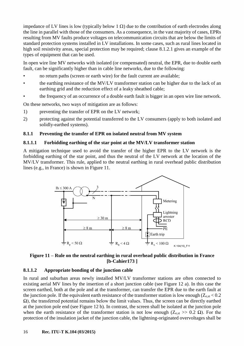
On system with isolated neutral or with resonant or high-impedance earthing, overhead lines are
usually not equipped with a metallic return path (neutral conductor or multi earthed earth wire) and
the total current of a double earth fault on the network is circulating through the earth and produces
EPR at each fault point. When earth fault occurs in an MV/LV substation the EPR is transferred from
the faulty substation through the LV neutral conductors to the LV installations (see Figure 8).
3

14 Rec. ITU-T K.104 (03/2015)
Figure 8 – MV fault at the MV/LV substation and transfer of the EPR in LV installations
(double earth fault on an overhead line network)
If an MV network is composed of cable lines, only that fraction of the double earth fault current,
which does not return through the cable sheath/screen, circulates through the station earths and
produces EPR. This EPR is transferred from the faulty MV/LV substation through the LV neutral
conductors to the LV installations (see Figure 9).
Figure 9 – MV fault at the MV/LV substation and transfer of the EPR in LV installations
(double earth fault on a cable network)
7.5.3 Conditions affecting the potential transfer on LV neutral system
The potential transfer on the neutral conductors is affected by the following two conditions:
1) the earthing arrangement at the MV/LV transformer station;
2) the LV system earthing.
Figure 10 – Earthing options of the MV/LV transformer station
Rec. ITU-T K.104 (03/2015) 15
For the earthing arrangement at the MV/LV transformer station one of the two options shown in
Figure 10 can be applied. Generally the scheme shown in Figure 10 a) is realized, i.e., the MV frames
are combined with the N bus to which the transformer neutral and the neutral conductors of the
outgoing lines are connected. This jointed terminal is earthed commonly through the effective
impedance to earth Ze,st of the MV/LV transformer station. The EPR Ue is given by the product of this
impedance and the current to the earth, Ie,st, i.e., Ue = Ze,st Ie,st. Note that the Ze,st value is the parallel
equivalent of the resistance Re to the earth of the station earth and the parallel resultant of the earthing
impedance ZN of the neutral conductors. The ZN could reduce, in a great extent, the Ze,st (see
Appendix III) and thus reduce the EPR as well, especially when the LV system earthing is TN (see
Appendix V). In this exceptional case, when the transfer potential is beyond the limits given in
[ITU-T K.68], the earthing for the MV frame represented by Re and the earthing of the neutral ZN
should be separated as shown in Figure 10 b). This is a mitigation technique that prevents the transfer
of EPR through neutral, to the customer’s premise (see the mitigation technique in clause 8.1.1).
The followings can be stated for the different LV system earthing from the point of view of transfer
of the MV/LV EPR through the neutral:
• the EPR is transferred in TN and TT systems through the neutral conductors due to its
connection to MV/LV station earth;
• the EPR is not transferred in IT systems through the neutral conductors because it is not
connected to MV/LV station earth.
The following significant differences between the TN and TT systems earthing are:
• In TN system earthing the neutral conductor is frequently earthed, i.e., at the consumer's
premises and at regular distances along the line (every 250 to 400 m) as specified by the
utilities. As a result:
– the input impedance of the neutral-to-earth loop is small (see Appendix V) and the
effective impedance to earth of the MV/LV transformer station is also small (see
Appendix III), and results in low station EPR;
– the transfer potential decreases rapidly with the distance from the station due to the
attenuation effect resulted by the frequent earthing of the LV neutral conductors (see
Appendix IV). Consequently, the total EPR is transferred to only those consumer's
premises, which are in the station’s neighborhood;
– the potential transfer from the MV network to the neutral of the LV network is blocked
at the MV/LV transformer when the LV neutral is not connected to the station earthing,
but the neutral conductors are earthed at the consumer's premise. In principle this
corresponds to the scheme shown in the Figure 10 b); however, the LV neutral earthing
points representing RLV are applied at the consumer’s premise. (See also the mitigation
technique given in clause 8.1.1.1).
• In the TT system earthing the neutral conductor is earthed only at a single point i.e., to the
MV/LV station earth. Consequently:
– the neutral conductors do not lessen the impedance to earth of the MV/LV transformer
station and do not lower the station EPR;
– the station EPR is practically transferred without any attenuation to customer’s premises.
8 Mitigation techniques
8.1 Protecting telecommunication lines serving LV installations (MV faults)
MV networks with a solidly-earthed neutral, carry lines with a multi earthed neutral. The neutral
conductor of the MV line is connected to the neutral of the LV lines. The EPR caused by single-phase
faults on the MV system is transferred to LV consumers through the LV neutral. In general, the earth
16 Rec. ITU-T K.104 (03/2015)
impedance of LV lines is low (typically below 1 ) due to the contribution of earth electrodes along
the line in parallel with those of the consumers. As a consequence, in the vast majority of cases, EPRs
resulting from MV faults produce voltages on telecommunication circuits that are below the limits of
standard protection systems installed in LV installations. In some cases, such as rural lines located in
high soil resistivity areas, special protection may be required; clause 8.1.2.1 gives an example of the
types of equipment that can be used.
In open wire line MV networks with isolated (or compensated) neutral, the EPR, due to double earth
fault, can be significantly higher than in cable line networks, due to the following:
• no return paths (screen or earth wire) for the fault current are available;
• the earthing resistance of the MV/LV transformer station can be higher due to the lack of an
earthing grid and the reduction effect of a leaky sheathed cable;
• the frequency of an occurrence of a double earth fault is bigger in an open wire line network.
On these networks, two ways of mitigation are as follows:
1) preventing the transfer of EPR on the LV network;
2) protecting against the potential transferred to the LV consumers (apply to both isolated and
solidly-earthed systems).
8.1.1 Preventing the transfer of EPR on isolated neutral from MV system
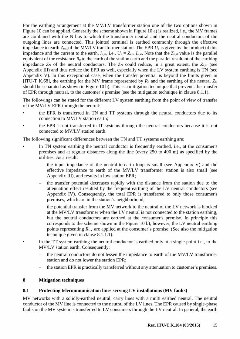
8.1.1.1 Forbidding earthing of the star point at the MV/LV transformer station
A mitigation technique used to avoid the transfer of the higher EPR to the LV network is the
forbidding earthing of the star point, and thus the neutral of the LV network at the location of the
MV/LV transformer. This rule, applied to the neutral earthing in rural overhead public distribution
lines (e.g., in France) is shown in Figure 11.
Figure 11 – Rule on the neutral earthing in rural overhead public distribution in France
[b-Cahier173 ]
8.1.1.2 Appropriate bonding of the junction cable
In rural and suburban areas newly installed MV/LV transformer stations are often connected to
existing aerial MV lines by the insertion of a short junction cable (see Figure 12 a). In this case the
screen earthed, both at the pole and at the transformer, can transfer the EPR due to the earth fault at
the junction pole. If the equivalent earth resistance of the transformer station is low enough (Ze,st < 0.2
Ω), the transferred potential remains below the limit values. Thus, the screen can be directly earthed
at the junction pole end (see Figure 12 b). In contrast, the screen shall be isolated at the junction pole
when the earth resistance of the transformer station is not low enough (Ze,st >> 0.2 Ω). For the
protection of the insulation jacket of the junction cable, the lightning-originated overvoltages shall be

Rec. ITU-T K.104 (03/2015) 17
limited by an MV type overvoltage protector applied between the screen and pole earthing (see
Figure 12 c).
Figure 12 – Rules on earthing of the screen of short MV junction cables
8.1.2 Protecting against potential transferred to LV consumers
The increasing use and interconnection of complex electronic telecommunications equipment, such
as ISDN terminals, modems and computers, at customers' buildings requires special care for
protecting against overvoltages and overcurrents. Such overvoltages and overcurrents include
exposure of serving telecommunications cables and power lines to lightning, and the coupling of AC
voltages onto the telecommunication cables due to faults on the external power system. Two
techniques are reviewed for the protection against this simultaneous overvoltage effect as follows:

18 Rec. ITU-T K.104 (03/2015)
8.1.2.1 Isolation techniques
Equipment at the subscriber's premises, which is powered from the LV supply network and connected
to the telecommunication network, should be protected against the potential transferred through the
neutral of the LV system by a unit providing appropriate isolation between the equipment ports. Such
units, for the protection of different telecommunication facilities, are already available in the market
and are reviewed in the following examples:
1) The isolation unit, LIU 3C, shown in Figure 13 can be used for the protection of public service
telecommunication network (PSTN) voice circuits. This isolation unit is powered by line
current for the line side and local power at the customer's side. Information is coded as
64 kbit/s streams and transmitted via short fibre links. The left-hand side is the line side and
the right-hand side is the customer's side. Two fibre links and the internal casing provide the
required isolation. It would be very easy to extend this to a greater distance. The isolation
unit is tested to 25 kVrms.
Figure 13 – Isolation unit for PSTN (voice) circuits (LIU 3C)
2) A unit similar in operation to LIU 3C is used for ISDN2e circuits, but has four fibre links.
The unit is tested to 25 kVrms (Figure 14). Analogue private circuits use a simple transformer
isolator and its attendant circuits, tested to 20 kVrms.
Figure 14 – Isolation unit for ISDN2e circuits (LIU 3C)
3) A transformer based solution can be used which is tested to 25 kVrms (minimum).
4) The isolation unit shown in Figure 15 can be used for the protection of asymmetric digital
subscriber line (ADSL) circuits. This isolation unit uses a transformer isolation solution, but
with a digital subscriber line (DSL) splitter filter, such that PSTN voice isolators can still be
connected. The transformer is a split winding type, so it is coupled across the windings on
the line side with a capacitor (with no DC current flow to upset the PSTN circuit). The left-

Rec. ITU-T K.104 (03/2015) 19
hand side is the line side and the right-hand side is the customer's side. The unit is tested to
25 kVrms.
Figure 15 – Isolation unit for ADSL circuits
8.1.2.2 Coordinated protection at customer's premises
Overvoltage protection may be required for the safety of personnel and for protection of equipment.
To provide this protection, it is necessary to bond metallic services and screens to the building earth
and install surge protective devices (SPDs) at the building entry point on power and
telecommunication conductors. Properly configured equipotential bonding within the building helps
to achieve the necessary protection, while also helping to ensure the safety of those using terminal
equipment. Such bonding configurations are detailed in [ITU-T K.21], [ITU-T K.35], [ITU-T K.45]
and [ITU-T K.66].
Equipment and personnel in a building are exposed to externally produced energy because conductive
services such as telecommunication lines, power lines, antenna leads, waveguides, earthing
conductors and metallic pipes penetrate the shell of the building. The penetration of conducted energy
is mitigated by interconnecting all of these with low-impedance bonding conductors to the main earth
terminal (MET) (Figure 16), or to the mesh-bonding network or common bonding network (CBN)
(Figure 17). This low impedance is achieved by keeping the length of bonding conductors short
(< 1.5 m). The use of low impedance bonding conductors is particularly important when there is a
significant risk of a direct lightning strike to the structure or to the line immediately adjacent to the
building. A combined utilities enclosure (CUE) can be used to house the primary protectors, both for
the mains electricity supply and the telecommunication supply, to achieve short bond wires. It also
has the advantage that all metallic services can enter at the same point and be bonded together. This
is the best method to protect all services in a customer's premise.
Where it is not possible to achieve the requirement for short bond wires or additional protection is
required, combination protection units (CPUs) may be used (Figure 18). CPUs contain the SPDs for
all ports. They are installed near the equipment and thus, also protect against overvoltages occurring
in internal wiring. CPUs shall be coordinated with the primary protector, as shown in Figure 18.
The proposed earthing and bonding methods are easy to implement in a new building. Therefore, in
new installations where practical, these recommendations should be followed. In existing
installations, it may be very difficult to modify the installation to comply with these bonding
requirements. It is therefore suggested that in older installations, an upgrade to comply with these

20 Rec. ITU-T K.104 (03/2015)
clauses should be considered only when a major wiring upgrade is being undertaken or there are
exceptional safety issues that require an upgrade.
Figure 16 – Co-location services next to a MET
Figure 17 – Common bonding network (CBN)

Rec. ITU-T K.104 (03/2015) 21
NOTE – SPDs 1), 2) and 3) need to be suitable for use on the mains as specified in [ITU-T K.66].
Figure 18 – Equipment protected by the same combination protection unit
(multiservice surge protection device (MSPD))

22 Rec. ITU-T K.104 (03/2015)
Annex A
Techniques for calculating the EPR in electric power systems
(This annex forms an integral part of this Recommendation.)
A.1 Network parameters affecting the EPR
The IEC defines the EPR as the voltage between an earthing system and reference earth [EN 50522],
[IEC 61936-1]. The "reference earth" (remote earth) is a point far enough away from the earthing
system that the electric potential of this point can be conveniently taken as zero. The EPR is the
product of the current to earth and impedance to earth of the installation. The current path to the earth
can be identified in different ways and therefore, the current to earth and impedance to earth of the
installation should be specified accordingly.
In the most practical cases the highest EPR in a substation is seen when an earth fault occurs in the
substation itself. The relevant currents and the impedances to earth are shown for this fault situation
in Figure A.1. These currents and impedances, and therefore the EPR, are affected by the following
network parameters.
Figure A.1 – Currents and impedance to earth relevant to the faulty substation
1) The short-circuit current, Isc = 3I0,sc depends on the impedance of the in-feed network
including the transformers and the lines feeding the fault. On HV systems, single-phase earth fault
current levels typically range between 5 and 30 kA. In an actual case its value shall be provided by
the power network operator. On solidly-earthed MV systems (a practice in North America), they
typically range between 1 and 10 kA. On isolated or resonant earthing neutral MV systems, similar
values can be expected during double earth faults.
The short-circuit current is the sum of the current 3I0 of the lines, feeding to the fault and the
circulating transformer current, IN = 3I0N:
Isc = 3I0,sc = 3I0 + IN (A.1)

Rec. ITU-T K.104 (03/2015) 23
Note that the circulating transformer current contributes neither to the current to earth nor to the EPR.
It only causes grid current between the faulty point and the earth connection point of the transformer
neutral, which causes internal voltages difference, such as step voltage.
2) The station impedance to earth Ze,st of a substation results from the contribution of the grid
resistance, Re in parallel with the outgoing lines carrying passive conductors, with the earth electrode
effect characterized by Ze.pl connected to the grid.
If the resistance to earth Re of the grid is not available from measurements, it can be estimated using
the following equation:
(A.2)
where is the soil resistivity, A is the area of the grid.
The earth resistance of the grid is approximately inversely proportional to the square root of its area
(see equation (A.2)).
The earth electrode effect of the outgoing lines carrying passive conductor can be classified
according to the type of passive conductor. In the case of a line, the earthing impedance represented
by its earth wire is proportional to the tower footing resistance Rt and thus to the square root of the
soil resistivity as well (see equation (I.4)). Values for input impedance of LV neutral-to-earth loop
are presented for different options in Appendix V.
Figure A.2 compares the earth resistance of grids of different dimensions to different types of lines
using the parameters given in Tables A.1 and A.2 [b-Cigre Guide]:
• a cable with a metallic sheath in direct contact with soil;
• a rural MV line carrying a multi earthed neutral typical of North American distribution
systems;
• an HV line carrying one earth wire.
In a 100 Ωm soil for example, a 100 m2 grid has a resistance of 4.4 Ω and this value is reduced to
0.44 Ω for a 10’000 m2 grid; the resistance increases linearly with the soil resistivity. The earth
impedance of lines is the input impedance of the earth conductor (earth wire or sheath/screen) to be
connected to the grid. An overhead HV line with resistance of 1 Ω/km earth wire, 300 m spans and
tower footings with a resistance of /30 has an earth impedance of approximately 1.5 Ω. This earth
impedance is increased to 4.2 Ω for a 1'000 Ωm soil.
ARe
4

24 Rec. ITU-T K.104 (03/2015)
Figure A.2 – Earth impedance Re of grids and different line types vs. soil resistivity
[b-Cigre Guide]
Table A.1 – Parameters of overhead lines used in Figure A.1
Rc
(/km)
GMR
(m)
Span
(m)
Re
()
MV line 0.5 0.002 100 /10
HV line 1 0.001 300 /30
Rc: conductor resistance, GMR: geometric mean radius
Re: tower footing resistance
Re: tower footing earth resistance
Table A.2 – Parameters of cable used in Figure A.1
Rc
(/km)
GMR
(m)
g
(S/km))
Cable 0.5 0.05 350/
g: sheath-to-earth conductance
The proposed simple expressions can be used for the estimation of the earth resistance of the grids
and the earth impedance of lines. The resistance of grids is proportional to the soil resistivity whereas
the impedance of lines is proportional to the square root of the soil resistivity. As a consequence, the
contribution of lines to the earth impedance of the installation increases with the soil resistivity, i.e.,
the relative importance of the lines with earth electrode effect is more significant.
The passive conductors (earth wires, cable sheath or counterpoise) associated with the in-feeding
power lines are referred to as return conductors. The difference between a return conductor and a
passive conductor of the outgoing lines with earth electrode effect is that, the return conductor of an
in-feeding line is doubly affected. In principle the current in the return conductor can be composed
of current fractions caused by the following two effects.
The first effect is the conductive coupling resulted by the connection to the grid and thus affected by
the EPR. As a result, a conductive current, Ie,cond occurs. Its magnitude is given by the ratio of the
EPR, Ue to the input impedance to earth, Ze,rt of the return conductor. This current of conductive

Rec. ITU-T K.104 (03/2015) 25
origin enters form the grid to the earth wire and gradually leaves it through the tower footing (or
continuous leakage of sheath). It becomes practically zero at a distance of three length constant (see
equations (8) to (10) for ). In fact, this effect is similar to the one of the passive conductors of the
outgoing lines with earth electrode effect. In another view point, the Ze,rt tends to reduce the overall
resistance to earth of the earthing system of the substation.
The second effect is the inductive coupling resulted by the mutual impedance between the phase
conductor group and the return conductor both with earth return. The electromotive force (emf)
induced by the 3I0 through this coupling causes an induced current which circulates in the earth wire
to earth loop. The induced current redistributes the 3I0 current and resulted currents in the steady zone
are those given for the earth wire by equation (A.3) and for the earth by equation (A.4). These currents
are expressed by the screening factor ks (equation (A.5)).
The screening factor (ks) corresponds to the fraction of the earth fault current of a line that contributes
to the EPR (see Appendix VII). On overhead lines without an earth wire, it is equal to 1. On HV lines
with one or two steel earth wire(s), the screening factor typically ranges between 0.8 and 0.95. If the
HV line is equipped with a low resistance (in the order of 0.1 Ω/km) earth wire, the screening factor
can decrease to approximately 0.5. On North American distribution lines carrying a multi earthed
neutral, the screening factor typically ranges between 0.5 and 0.7. Cables have low screening factors
due to the high level of inductive coupling between the phase conductor and the screen. The screening
factor of MV or HV cables typically varies between 0.05 and 0.5; the lower values correspond to the
low resistance (less than 0.1 Ω/km) of the screen/sheath of these cables.
The current share between the earth and earth wire expressed by the screening factor is, strictly
speaking, valid only in the steady zone of the line. Close to the substation (at distance less than 3)
the induced current tends to leave the earth and enter to the earth wire. The rate of this current
exchange depends on the value of the grid impedance, Ze,st to earth of the station. At the substation
end the induced earth current Ie,ind would remain constant, i.e., ks3I0 if Ze,st 0 (very low), while Ie,ind
would decrease to zero if Ze,st (very high). The conductive current, also changes with distance.
Its value goes down from its starting value of Ie,cond =Ue/Ze,rt to practically zero at a distance of 3
from the substation. Consequently, the changes in both components of the return current tend to
decrease the current through the impedance to earth and thus the EPR as well. The rate of decrease in
the EPR is smaller than the rate of a possible decrease (improvement) in the impedance to earth of
the grid. The effect of the above mentioned current exchange is referred to as end effect and is
approximated by modified (end effect) value of the screening factor.
Due to the above-mentioned end-effects, the value of the equivalent earth impedance has a contrary
effect on the EPR. On the one hand, the increase of the equivalent earth impedance tends to increase
the EPR, but on the other hand, decreases the substation earth current which opposes the increase of
the EPR. In practical cases the final result is the decrease in the EPR, due to the decrease
(improvement) in the end-effect screening factor.
A.2 Techniques for calculating the EPR
In case of an actual EPR investigation the following three levels of calculations can be followed
depending on: the complexity of the task, the accuracy required, the availability of the input data and
the available calculation technique:
1) use of the complex simulation for the actual network and fault conditions;
2) calculation for the in-feeding lines terminated by station impedance to earth;
3) calculation by the screening factor of the in-feeding lines terminated by equivalent impedance
to earth.

26 Rec. ITU-T K.104 (03/2015)
A.2.1 Use of complex simulation for the actual network situation and fault conditions
In the case of a complex situation, the calculation of the EPR of a substation needs a comprehensive
procedure (e.g., ITU-T Directives Vol. II and Vol. III, [ITU-T K.26], [b-Paul]) and requires dedicated
computer software, e.g., [b-Sollerkvist]. In fact, the complete network with the elements shown in
Figure A.1 is simulated in the calculation. The following list gives a few conditions and system
parameters that have to be taken into account for accurate simulation:
1. The fault contributing to the maximum value of the EPR may be located outside the
substation. This situation can occur in the substation where high power Y-∆ transformer(s)
is (are) installed with solidly-earthed neutral(s). In this case, the fault distance at which the
maximum value of the EPR occurs has to be identified by short-circuit analyses. The currents
injected to the grid by the transformer neutrals are the primary source of the EPR.
2. If transformers with earthed Y-Y connections are used, a fault at one voltage level causes the
circulation of earth fault currents at different voltage levels. These contributions must all be
taken into account.
3. If transformers with earthed Y-Y-∆ connections are used, circulating transformer neutral
current is flowing, i.e., a portion of fault current flows back to the transformer neutral point
via the metallic parts of the earthing system without ever discharging into soil.
NOTE – The currents mentioned in points 1 to 3 are obtained from the short-circuit analyses of the
power system and should be made available by the power system operator.
4. If two or more lines are in close proximity, a significant error can be introduced if the
calculation of the earth impedance of the lines is done separately. For example, if two cables
are located in the same street only a few metres apart, the coupling between them (in the case
of metallic sheath in direct contact with the soil the conductive coupling may be significant
as well) should be taken into account when estimating the contribution of these two lines to
the reduction of the earth impedance of the substation.
5. Simple equations such as (I.4) can be used for the calculation of the earth impedance of lines
if they are long. However, if they are shorter than a few times the length constant (see
equations (8) to (10) for ) or if their parameters change within this distance, more elaborate
calculations are required.
6. If the screening factor of a line(s) that contribute(s) to the fault current change(s) within a
distance shorter than a few times the length constant, inductive (screening factor) and
conductive (impedance representing the line earth electrode effect) couplings cannot be
treated separately. The next clause gives an example on how this problem can be solved.
A.2.2 Calculation for the in-feeding lines terminated by station impedance to earth
In the most practical cases, calculation of the EPR of a substation grid can be simplified to a great
extent with the circuit representation constituted by the following two key elements:
1) The line(s) in-feeding to the fault, which is (are) composed of the live (phase) conductors and
the passive return conductors with earth electrode effect. Both kinds of conductors are individually
represented in the simulation calculations, thus the voltages and currents are obtained from the
calculation for the passive conductors as well. The passive conductors of the in-feeding lines are
connected to the earthing system of the substation.
For the in-feeding lines the zero sequence currents flowing in the active conductors to the fault are
given as follows:
• in an HV/MV substation the total zero sequence current, 3I0 in the in-feeding line(s) as the
difference of the short-circuit current and the circulating-transformer neutral-current:
3I0 = Isc – IN=3I0sc – IN;

Rec. ITU-T K.104 (03/2015) 27
• in an MV/LV substation it is equal to the phase-to-earth short-circuit current 3I0sc in a system
with solidly-earthed neutral, while it is equal to the double earth fault current 3I0 = Isc,2Ff =
3I0sc,2Ff in a system with isolated or resonant earthing.
For design purposes (e.g., settings of the relay protection) the above mentioned currents are known
from the short-circuit analyses for the power system.
2) The impedance to earth of the earthing system is represented by the effective station
impedance to earth, Ze,st of the substation, which is composed of the resistance to earth, Re of the
earthing grid and the parallel equivalent of the impedance to earth of the connected passive (not
in-feeding on the fault) lines with earth electrode effect.
The procedure for calculating the substation EPR is composed of the following steps:
1. design of the earth grid and evaluation of the earth resistance Re;
2. evaluating the total earth impedance Ze,pl provided by the passive conductor-to-earth loops
connected to the grid;
3. calculating the effective station impedance to earth Ze,st of the substation (parallel resultant
of the above two values). This will be the terminating impedance of the return conductor to
earth loop(s) at the substation end;
4. identifying the equivalent earth current, as the difference between the earth fault current
(Isc = 3I0,sc) and the circulating-transformer neutral-current IN (both are given as input data),
which should be injected zero sequence way through the active conductors into the grid;
5. solving the in-feeding line system by an appropriate multi-conductor line solution technique
(e.g., ITU-T Directives Vol. II and Vol. III, [ITU-T K.26], [b-Paul]). From this solution the
voltage(s) and current(s) of the passive return conductors will be obtained as a function of
the distance from the substation, i.e., the voltage and current length profiles. The voltage of
the passive conductor at the substation end is equal to the station EPR itself.
The voltage length profiles of the return conductors give the voltage transferred by the passive
conductors of the in-feeding lines.
The effective station impedance to earth of an HV/MV substation is demonstrated in Figure A.3. It
is composed of the resistance to earth, Re of the earthing grid and the parallel equivalent of the
impedance to earth of the connected passive conductors with earth electrode effect, e.g., the cable
sheath/screen of cable with earth electrode effect or multipoint-earthed neutral of the MV lines
according to North-American practices (see in the pink dotted line square). The passive conductors
are the earthed conductor(s) of those lines of the active conductors that do not carry any fault current
or do not have any active conductors at all (e.g., pipes or rails). In fact, these passive earth conductors
are functioning either as horizontal buried wires, or strips or multipoint earthed conductors. The input
impedance of each passive conductor-to-earth loop is electrically parallel connected with each other
and represents resultant impedance to earth of the passive conductors of the MV, Ze,MV. The passive
earth conductors create current paths from the grid to the earth in addition to the resistance to earth,
Re of the earth grid. Therefore, the equivalent earth impedance Ze,st (inside the blue dotted line square)
of the substation is the parallel equivalent of the resistance Re to the earth of the grid and the resultant
impedance Ze,MV of the connected passive earth conductors.

28 Rec. ITU-T K.104 (03/2015)
Figure A.3 – Scheme showing the in-feeding HV power lines and the MV lines with earth
electrode effect contributing to the equivalent impedance to earth [b-Cigre Guide]
The calculation of the EPR of MV/LV transformer stations due to earth fault is identical to the one
described above for the HV/MV substation. However, the composition of both the passive earthing
elements and the return conductors are those shown in Figure A.4.
The return conductors of the MV network are composed of:
• the sheaths of MV cables having continuous contact (leakage) to the earth, i.e., older type
lead-sheathed cables with steel-tape armoring;
• the screens of MV cables (with insulating jacket) which are locally earthed at the MV/LV
transformer stations and at the HV/MV substation;
• North American distribution lines carrying a multi earthed neutral (see the neutral of the
aerial line marked by dotted line in Figure A.4).
The passive earthing conductors of the LV network resulting in the shunting impedance Ze.LV are
composed of (see in the pink dotted line square in Figure A.4):

Rec. ITU-T K.104 (03/2015) 29
Figure A.4 – Scheme of an MV/LV substation showing the in-feeding MV power
lines and the passive lines with earth electrode effect contributing to the
equivalent impedance to earth [b-Cigre Guide]
• In the case of a TN system the neutral conductors of the LV feeders (either overhead or cable
lines), which are locally earthed at the consumer's premise and certain points of the lines
correspondingly to the utility requirements. The impedance to earth of the neutral is highly
reduced when the neutral is connected to the pipe system of the metallic public utility
networks (e.g., water, gas) at the customers applying the TN system (see examples for
numerical values in Appendix V).
In the case of a TT system, the LV neutral is earthed only at the MV/LV transformer station,
but the neutral conductors of the LV feeders are not earthed locally at the consumer's premise.
This condition has the following consequences:
1) The neutral conductors are not multiple-earthed, thus they have no earth electrode effect
any more. Such a neutral conductor system does not reduce station impedance to earth.
Consequently, a double earth fault causes much higher EPR in the MV/LV transformer
station compared to a TN system (see Appendices III and VI).
2) The station EPR is transferred by the neutral conductor of the TT system to the
consumer's premises (mains port) without any attenuation in contrast to the TN system
(see Appendix IV).
3) The potential transferred by the neutral conductor appears across the mains port and the
locally earthed frame of the consumer's appliances.
NOTE – In the case of the North American practice the multi earthed MV neutral conductor is cross-
connected to the LV neutral at a transformer feeding an individual consumer, thus it has the analogy
with the TN system.
• The sheaths of LV cables having continuous contact (leakage) to the earth, i.e., older type
lead-sheathed cables with steel-tape armoring.
Finally, it should be noted that the effective station impedance to earth, Ze,st as defined in this clause
is different from the equivalent impedance to earth applied in the next clause, because the effective
station earth impedance does not involves the additional earthing effect (reduction) due to the return
conductors of those lines which are in-feeding the fault current to the substation.

30 Rec. ITU-T K.104 (03/2015)
A.2.3 Calculation by the screening factor of the in-feeding lines terminated by equivalent
impedance to earth
When the passive conductors of the in-feeing power lines are uniform along the line and the lines are
long (at least six times the length constant) then the EPR calculation can be originated from the
screening factor of the return conductors of the in-feeding lines. The two criteria mentioned involves
that the current induced in the return conductor(s) to earth loop reaches its steady value at least along
the middle zone of the line.
When zero sequence currents 3I0 are present on a three-phase transmission line, they induce
longitudinal emf: E = Zm·3I0 per unit length, where Zm is the mutual impedance between the groups
of the phase conductors and the return conductor(s), per unit length (see in Figure I.3). Assuming a
perfectly earthed return conductor (e.g., earth wire) this emf causes an induced current which is
circulating in the earth wire to earth loop. Its value, which is equal to the earth wire current Iew, is
given by:
(A.3)
The induced current in the earth:
𝐼𝑒,𝑖𝑛𝑑 = 3𝐼0 − 𝐼𝐸𝑊 = 𝑘𝑠3𝐼0 (A.4)
where µ is the earth wire/return conductor factor and ks is the screening factor of the earth wire/return
conductor.
The screening factor defined as the ratio of the earth current and the 3I0 is given by:
(A.5)
For a cable connected to the substation, instead of the earth wire screening factor, the cable sheath
screening factor has to be used in the equation above for Ie,ind.
For cables with insulated metal sheath, which lead fault current to the substation, the cable sheath
screening factor is the primary effect. In addition, the chain impedance (cable sheath/neighbouring
earth grids) can be considered if the cable is significantly longer than the sections forming the chain
impedance.
For the determination of the screening factors further information is given in Appendix VII.
The EPR of an HV/MV transformer station can be calculated on the basis of the network scheme and
the equivalent circuit shown in Figure A.5.
For the determination of the equivalent current to earth Ieq the following current components are
considered:
Isc=3I0sc=3I0 + IN Three times zero sequence current of the earth fault current
3I0 Three times zero sequence current of the line
IN The circulating transformer neutral current
Ie Current to earth (cannot be measured directly)
(A.6)
For an earth fault in a three-phase system and for a similar return conductor screening factor of n
in-feeding lines connecting to the substation, the current to earth can be determined by equation (A.6)
the current shall be Σ3I0 the phasor sum of the zero sequence currents of the in-feeding lines.
0 0 03 3 (1 )3m
ew s
s
zI I I k I
z
s
ms
Z
Zk 1
0
ew0
0
e
3
- 3 =
3 I
II
I
I
00 33 IkIIkI sNscseq

Rec. ITU-T K.104 (03/2015) 31
If the earth wire reduction factors of the lines A, B, C ... leaving the substations are different, the
current to earth is given by:
Ieq = kA 3I0A + kB 3I0B + kC 3I0C + …
where:
I0A is the zero sequence current of a phase conductor (for example phase L1) of the
line A, I0B of the line B, etc.
kA is the earth wire screening factor of the line A, kB of the line B, etc.
For the determination of the equivalent impedance to earth Zeq the following current components:
Re resistance to earth of the mesh earth electrode (earthing grid) (Calculated by
sophisticated technique [b-CDEGS] or measured according to [EN 50522],
[IEEE 81-2012]
ZeHV input (earth wire/tower footing chain) impedance of the return conductors of
the in-feeding lines. In case of n in-feeding line their parallel equivalent (see
equation (A.8))
ZeMV input (earth wire/tower footing chain) impedance of the passive (not
in-feeding) lines. In case m not in-feeding line their parallel equivalent (see
equation (A.9))
The equivalent impedance to earth is given by the following expression:
(A.7)
When there are n in-feeding lines having identical chain impedance of ZHV
each with their parallel
equivalent:
(A.8)
Similarly for m not in-feeding lines with ZMV
chain impedance each their equivalent impedance is:
(A.9)
Such a simple calculation of the parallel equivalent impedance is valid only in the case where the
lines are not coupled with each other. (For consideration of cable groups in the same trench (see ITU-
T Directives Vol. II clause 4.3.7, [ITU-T K.26].)
Finally, the EPR in case of earth fault is given by the product of the equivalent impedance to earth
and the overall current to earth:
(A.10)
eHVeeMV
eq
ZRZ
Z111
1
n
ZZ HV
eHV
m
ZZ MV
eMV
eqqee IZU

32 Rec. ITU-T K.104 (03/2015)
Figure A.5 – Network scheme and equivalent circuit demonstrating the current to earth Ieq
and equivalent impedance Zeq to earth for an earth fault in an HV/MV transformer station

Rec. ITU-T K.104 (03/2015) 33
Appendix I
Calculation of fault current distribution
(This appendix does not form an integral part of this Recommendation.)
NOTE – This appendix is based on [b-Cigre Guide].
On low impedance or solidly-earthed systems, both single-phase and phase-to-phase to earth faults
cause high zero sequence currents to circulate between the substation and the fault location (see
Figure I.1). EPRs appear both at the fault location and at the substation.
On isolated or compensated neutral systems, only double earth faults lead to high zero sequence
currents circulating between the two faults (see next figure). EPRs appear at both fault locations.
Double earth faults are much less frequent than single-phase faults. A good guide to the calculation
of the fault current distribution can be found in the ITU Directives Vol. V clause 5, [ITU-T K.26].
The calculation of the zero sequence currents in the earth wires and the earth, involves a two stage
process. First the currents are calculated assuming there is no voltage difference between the earth
wire and the earth (i.e., assuming a perfect earthing). At the fault location and at the transformer or
generator neutral feed point there will be an EPR which will lead to a voltage difference between the
earth wire and the earth. There will also be a voltage difference generated at points where the earth
wire type or layout of the conductors change. The distribution of earth wire currents is then
recalculated allowing for the voltage gradient produced at these zero sequence source and sink points.
The calculations can be performed separately if all impedances are linear. If the slight nonlinear
resistance and internal inductance of the steel wires have to be considered then an iterative approach
has to be adopted.
Figure I.1 – Faults leading to the circulation of high zero sequence currents depending on
transformer neutral connection
When zero sequence currents I0 are present on a three-phase transmission line they induce return
currents in the earth wires if it is earthed as shown in Figure I.3. Assuming a perfectly earthed earth
wire, only the induced current is circulating in the earthed wire and the earth wire current Iew is given
by:
34 Rec. ITU-T K.104 (03/2015)
Figure I.2 – Transmission line zero sequence currents in phase and earth wires
(I.1)
where zm is the mutual impedance per unit length between the earth wire or wire bundle and the phase
conductors or conductor bundles, zs is the earth-return impedance per unit length of the earth wire or
wire bundle, μ is the coupling factor between the earth wire and phase conductors and ks is the
screening factor of the earth wires ( ). The return current through the earth Ie is:
(I.2)
These currents will not cause a voltage between the earth wires and the earth.
The source and sink points which are causing the circulating zero sequence currents (e.g., a fault) will
create a voltage difference between the earth wires and the earth due to the EPR and this will lead to
a redistribution of the current flowing in the earth wires and the earth. The redistribution of this current
depends on the impedance per unit length of the earth wire and the tower footing resistance Rt. The
equivalent circuit is as shown in Figure I.3. The current in each earth wire span decreases with
distance from the source or sink points (fault location, neutral earth point) and is a function of the
number of spans n from that point, where n=0 is the point considered (e.g., fault location). For the
uniform case with non-insulated earth wires the span earth current Id between towers n-1 and n is
given by:
(I.3)
where Zc is the impedance of the infinite long distributed chain of earth wires and tower footing
resistance as seen from the start and neglecting the overlapping of the tower footing resistance, and
is given by:
(I.4)
where zs is the impedance of the earth wire with earth return, per span, and Rt is the tower footing
resistance [b-Endrenyi].
0 0 03 3 (1 )3m
ew s
s
zI I I k I
z
1sk
0 03 3e ew sI I I k I
1
03( 1, )
2
n
s t t
d
t c t c
k I R RI n n
R Z R Z
0.5 4 0.5c s s t s s t sZ z z R z z R z

Rec. ITU-T K.104 (03/2015) 35
Figure I.3 – Earth and earth wire currents due to a phase-to-earth fault a) induced earth and
earth wire currents b) equivalent circuit for the distributed earth wire currents
The current to earth It at tower n, which gives rise to a footing EPR, is:
(I.5)
Near a substation all the connecting lines to the substation and the zero sequence current fed from
the substation itself need to be taken into consideration. The earth electrode of the substation can be
treated like a tower footing. Figure I.4 shows two possible situations of an internal substation fault
and a remote fault to the substation.
For an internal fault (Figure I.4 a) the earth current at the substation Ie is the sum of all the line earth
currents flowing into the station:
(I.6)
where n is the number of lines, ksl is the screen factor and I0l is the zero sequence current in line l.
For a remote fault (Figure I.4 b) the earth current is given by the current from the feed transformer
and in general, if other connected lines have a different screen factor then:
(I.7)
The induced earth wire current can be approximately expressed by the difference of the two involved
screening factors (see Figure I.6).
If the earth wire is insulated, then usually the insulators or spark gaps will flashover at the tower
containing the fault and at some adjacent towers, depending of the resistance of the tower footings.
1
03( )
2
n
s c t
t
t c t c
k I Z RI n
R Z R Z
0
1
3n
e sl l
l
I k I
0 0
1
3 ( )3n
e sl t sl si i
i
I k I k k I

36 Rec. ITU-T K.104 (03/2015)
Figure I.4 – Earth fault currents at a substation G for a) internal fault b) remote fault on a
connected line
For a double circuit line feeding a fault on one circuit, as shown in Figure I.5, then the induced
currents on the earth wire are ks(3I0a+3I0ab) between substation A and the fault and ks(3I0b-3I0ab)
between the fault and substation B. The current source for the distributed earth wire currents at the
fault location, however, is ks(3I0a+3I0b). If the fault involves both circuits then the induced current is
ks times the total zero sequence currents on both line sections.
Figure I.5 – Zero sequence currents for double circuit lines
For non-uniform lines, where all the line parameters and footing resistances are known, a solution
can be found by referring to the equivalent circuit given in Figure I.6.

Rec. ITU-T K.104 (03/2015) 37
Figure I.6 – Earth and earth wire currents due to a phase-to-earth fault showing a
redistribution of the earth wire currents at the point of connection to a cable due to change in
ks for a) induced earth and earth wire currents b) equivalent circuit for the redistributed
earth wire currents
If the type or number of earth wires change, such that the earth wire screening factor changes, then
the point of change represents another earth current source point that can lead to an EPR and the
equivalent circuit is as shown in Figure I.6, where there is an additional source/sink point of
magnitude (ks2-ks1)3I0 located at the transition point between the cable and the overhead line.

38 Rec. ITU-T K.104 (03/2015)
Appendix II
Through tower earthing during power line faults
(This appendix does not form an integral part of this Recommendation.)
NOTE – This appendix is based on [b-Cigre Guide].
This appendix presents an algorithm for the calculation of the current distribution along a shield wire
in the case of a fault occurring on a relevant power line. In particular, attention is focused on the
calculation of the currents injected into the soil at all the tower locations. The EPR produced into the
earth is strongly influenced by these currents. Moreover, some calculation examples are given by
varying the main parameters influencing the phenomenon within typical ranges.
II.1 Equivalent circuit of the earth wire with earth return
The circuit representing the earth wire with earth return can be modelled by means of a cascade of
cells as shown in Figure II.1.
Figure II.1 – Lumped elements representation of earth wire with earth return circuit
In Figure II.1, the lumped parameters have the following meaning:
• Rt1 and Rtn+1 are the substation earth grid resistances;
• Rtk are the tower earthing resistances (k=2,3,…,n);
• Zk are impedances with earth return associated with the k-th cell that has to be identified with
the k-th span between towers k and k+1 (k=1,2,…,n).
When a single fault1 to earth occurs at the location sk:
• a current J(sk)=JA(sk)+JB(sk) injected on the earth wire at the fault location sk (JA(sk) and
JB(sk) being the fault currents flowing on the faulted phase and coming from the two feeding
substations);
• the fault currents coming from the two feeding substations JA(sk) and JB(sk) induce, due to
inductive coupling, an electromotive force (emf) on the earth wire, earth circuit. The induced
emf in the generic i-th cell is given by the expression:
(II.1)
____________________ 1 Consider the case of low impedance or solidly-earthed systems.
kiLsJBzm
kiLsJAzmF
iki
iki
i

Rec. ITU-T K.104 (03/2015) 39
zmi being the per unit length mutual impedance between the faulty phase-earth circuit and
shield wire-earth circuit and Li being the length of the i-th span. The inducing currents JA(sk)
or JB(sk) must be known2 and have opposite signs.
Therefore, in the equivalent circuit in Figure II.1 it is necessary to add suitable current and emf
generators as represented in Figure II.2:
Figure II.2 – Earth wire – earth equivalent circuit with a faulty phase
In the case of two earth wires, the equivalent circuit represented in Figure II.2 can still be used
provided that the longitudinal element of each cell represents the the venin equivalent of the parallel
of the two earth wires (see Figure II.3).
Figure II.3 – The venin equivalent circuit of two coupled earth wires
In Figure II.3 and with reference to the k-th cell, Z1k and Z2k are the impedances with earth return of
the two shield wires, Z12k is the mutual impedance between the two circuits and F1k and F2k are the
induced emf by inductive coupling with the faulted phase.
Explicit expressions for Zeqk and Feqk are:
(II.2)
(II.3)
II.2 Solution of the circuit
The above two-conductor line circuit can be solved by an appropriate calculation technique such as
given in ITU-T Directives Vol. II and Vol. III, [ITU-T K.26].
____________________ 2 They are a function of fault location and have to be previously calculated (generally by the power system
operator).
kkk
kkk
kZZZ
ZZZZeq
11221
1221 2
kkk
kkkkkk
kZZZ
ZZFZZFFeq
21221
12211212

40 Rec. ITU-T K.104 (03/2015)
II.3 Example of application
In this example, consider a single circuit power line, 30 km long, equipped with one earth wire and a
span length of 300 m; suppose that a fault occurs at km 15 and that the fault current is 10 kA (5 kA
coming from substation A and 5 kA coming from substation B).
Calculations were made by considering different types of earth wires (see Table II.1) and different
values of tower earthing resistance related to different values of soil resistivity. (Rt=10 Ω with soil
resistivity =300 Ωm; Rt=50 Ω with soil resistivity =1500 Ωm, Rt=100 Ω with soil resistivity
=3000 Ωm). At both ends of the line, two substation earth grids having an area Agrid of 400 m2; their
resistance has been estimated by means of this simplified equation:
(II.4)
(thus: with =300 Ωm Rgrid=6.65 Ω; with =1500 Ωm Rgrid=33.23 Ω; with =3000 Ωm,
Rgrid=66.47 Ω).
Table II.1 – Earth wire characteristics
Type of earth wire Diameter [mm] Resistance [Ω/km]
Steel 10.5 2.42
Alumoweld 11.5 1.07
Copperweld 12.3 0.49
Figure II.4 to Figure II.6 represent the current It injected into the soil at tower locations along the
route of the power line.
Looking at Figure II.4 to Figure II.6, shows that by increasing the value of the earthing resistance a
decrease of the magnitude of the injected currents at the towers near the fault location, however, at
the same time, the curves tend to become flater showing a kind of "balance effect". The final result
shows many more towers along the power line that are significantly involved in the earth wire current
dissipation to soil.
The same considerations should be taken into account with respect to the earth wire characteristics.
For given values of the tower earthing resistance, the curves tend to be more balanced by decreasing
the per unit length resistance of the earth wire.
To conclude, in the case of soil with low resistivity and a steel earth wire, a high current dissipation
is shown (essentially concentrated near the faulty location). In comparison, in the case of soil with
high resistivity and a copperweld earth wire, a larger number of towers contribute to dissipate the
current in a more uniform way along the line
grid
gridA
R
4

Rec. ITU-T K.104 (03/2015) 41
Figure II.4 – Current injected into the soil at the earthing points
for different kinds of earth wire: Rt=10 Ω, Isc = 10 kA
Figure II.5 – Current injected into the soil at the earthing points for
different kinds of earth wire: Rt=50 Ω, Isc = 10 kA

42 Rec. ITU-T K.104 (03/2015)
Figure II.6 – Current injected into the soil at the earthing points
for different kinds of earth wire: Rt=100 Ω, Isc = 10 kA

Rec. ITU-T K.104 (03/2015) 43
Appendix III
Impedance to earth of MV/LV transformer stations
(This appendix does not form an integral part of this Recommendation.)
NOTE – This appendix is based on [b-Cigre Guide].
III.1 Types of measured transformer stations
This clause presents the results of site measurements of the impedance to earth of 20 kV / 0.4 kV and
10 kV / 0.4 kV transformer stations that feed rural overhead or cable LV lines. The measurements
were made in the 40 Hz to 8000 Hz frequency range, with the aim of determining the global
impedance to earth and its components, i.e., the input impedance of the LV neutrals and the resistance
of the local earthing. Note that the global impedance of the station is equal to the equivalent
impedance to earth only in the case when the MV feeding line has no return earthed conductor (sheath
or earth wire). In other cases the measured global impedance is smaller than the equivalent earth
impedance of the station. In these cases, the measured value could be modified with the cable sheath-
to-earth or earth wire-to-earth loop input impedance of the MV line(s).
The measured transformer stations can be classified into the categories identified in Table III.1.
III.2 Measurement method
The scheme of the applied measurement method is shown in Figure III.1. The measuring current was
injected between the neutral bus and the current probe. Measurements were taken at discrete injected
frequencies avoiding the harmonic frequencies. Both the current and voltage probes were located 80-
100 m away from the transformer station in a perpendicular direction to the MV feeder and also as
far as possible from the earthing of the LV lines.
The measuring current flowing into the neutral conductors, local earth and the neutral of the
transformer (if possible) were separately measured by Rogowski coils. The applied measuring
technique is shown in Figure III.2. The injected and the part currents and also the EPR of the neutral
bar were measured by a selective meter. The global impedance to earth and the impedances to earth
of the neutral conductors have been calculated as the ratio of the EPR and the appropriate current.
The measurements made by some commercially available earth resistance and resistivity measuring
instrument apply the same principles, but the measured values are processed and thus the impedance
results themselves are monitored.

44 Rec. ITU-T K.104 (03/2015)
Table III.1 – The characterization of the measured transformer stations
Station Type of MV line Type of LV lines Pipeline Environment
Station 1 overhead line 3 lines with plastic
insulated cables plastic new, suburban
Station 2 overhead line
3 lines with plastic
insulated cables, 1
overhead line
steel,
connected rural
Station 3 overhead line 4 lines with plastic
insulated cables plastic new, rural
Station 4 lead sheathed arm. cable with
cont. leakage to the earth
7 lines, mixture of
overhead lines and cables
steel,
connected rural
Station 5 lead sheathed arm. cable with
cont. leakage to the earth 5 overhead lines
steel,
connected week-end place
Station 6 lead sheathed arm. cable with
cont. leakage to the earth
4 overhead lines, 2 lines
with plastic insulated
cables
steel,
connected week-end place
Station 7 plastic insulated cable 7 lines with plastic
insulated cables plastic new, suburban
Station 8 plastic insulated cable 5 lines with plastic
insulated cables plastic new, suburban
Station 9 plastic insulated cable 8 lines with plastic
insulated cables mixed rural
Station 10 overhead line 4 lines with plastic
insulated cables plastic new, suburban
Station 1 overhead line 2 lines with plastic
insulated cables
steel,
connected week-end place
Station 12
(Note) plastic insulated cable
6 lines with plastic
insulated cables plastic city centre
Station 13
(Note) mixed insulated cable line
4 lines with plastic
insulated cables plastic city centre
NOTE – 10 kV/0.4 kV station, otherwise 20 kV/0.4 kV station.

Rec. ITU-T K.104 (03/2015) 45
Figure III.1 – Circuit scheme of earthing measurement of an MV/LV transformer station
a) Current measurement of the current in the LV neutral of the MV/LV transformer and in the neutral
conductors of the outgoing LV lines

46 Rec. ITU-T K.104 (03/2015)
b) Current measurement in the neutral conductors of the outgoing LN lines
Figure III.2 – Measurement of the currents in an MV/LV transformer station by flexible
clamp-on current transformer (Rogowski coils)
III.3 Results of the measurements
The global impedance of the measured thirteen transformer stations are plotted vs. the frequency in
Figure III.3 and are given for characteristic frequencies in Table III.2. The global impedance of the
transformer station and its components measured by Chauvin-Arnoux instrument are plotted in
Figure III.4.
III.4 Conclusions
The global impedance to earth of the transformer stations is very small at the mains frequency. This
essentially results from the small input impedances of the LV neutral conductors, which are in line
with the values obtained from the simulation calculation assuming frequent customers (Lt = 25 m),
low resistance of the discrete earthing structures (Rf = 3 ) and metallic connection to steel pipe
(see Appendix V).

Rec. ITU-T K.104 (03/2015) 47
a) Frequency range: 50 Hz to 8'000 Hz
b) Frequency range: 50 Hz to 200 Hz
Figure III.3 – Global impedance to earth of the 10/0.4 kV and 20/0.4 kV transformer stations
characterized in Table III.1

48 Rec. ITU-T K.104 (03/2015)
Table III.2 – Values of the impedance to earth of MV/LV transformer stations
in three frequencies
Station No. Frequency [Hz]
50 1'900 8'000
1 0.147 0.300 0.480
2 0.182 0.608 1.245
3 0.239 0.612 1.260
4 0.060 0.224 0.422
5 0.084 0.330 0.977
6 0.064 0.295 0.360
7 0.140 0.975 1.684
8 0.104 0.510 1.228
9 0.039 0.295 0.627
10 0.122 0.951 2.000
11 0.331 1.181 2.145
12 0.028 0.311 1.236
13 0.050 0.312 0.667
Station 6 Station 4
Z g
lobal
im
ped
ance
of
the
stat
ion
Z l
oca
l ea
rthin
g e
lect
rod
e
0.00
0.05
0.10
0.15
0.20
0.25
0.30
0.35
0.40
0.45
0 1000 2000 3000 4000 5000
Frequency [Hz]
Z g
lob
al [
Oh
m]
Iterative impedance 4pole measurement Obj:01 Test 01
0.00
0.05
0.10
0.15
0.20
0.25
0.30
0 1000 2000 3000 4000 5000
Frequency [Hz]
Z g
lob
al
[Oh
m]
Iterative impedance 4pole measurement Obj:02 Test 01
0.00
0.20
0.40
0.60
0.80
1.00
1.20
0 1000 2000 3000 4000 5000
Frequency [Hz]
Z lo
ca
l [O
hm
]
selective Impedance into Ground Obj:01 Test 02
0.00
0.20
0.40
0.60
0.80
1.00
1.20
1.40
0 1000 2000 3000 4000 5000
Frequency [Hz]
Z lo
ca
l [O
hm
]
Selective impedance into ground Obj:02 Test02

Rec. ITU-T K.104 (03/2015) 49
Z i
np
ut
of
the
com
bin
ed n
eutr
als
Figure III.4 – The measured global impedances of the MV/HV transformer stations and
their components
0.00
0.10
0.20
0.30
0.40
0.50
0.60
0.70
0.80
0 1000 2000 3000 4000 5000
Frequency [Hz]
Z i
n [
Oh
m]
selective impedance into PEN wire Obj:01 Test 03
0.00
0.20
0.40
0.60
0.80
1.00
1.20
1.40
0 1000 2000 3000 4000 5000
Frequency [Hz]
Z in
[O
hm
]
selective impedance into PEN wire Obj:02 Test 05

50 Rec. ITU-T K.104 (03/2015)
Appendix IV
Transferred voltage and current by means of LV neutral conductors
(This appendix does not form an integral part of this Recommendation.)
NOTE – This appendix is based on [b-Cigre Guide].
IV.1 System modelling, options and parameters
The neutral lines connecting to an MV/LV transformer station affect both the global impedances, as
well as the EPR of the transformer station and the potential transferred to the LV customers. The
effects of the different parameters of the neutral line system are investigated by a simulation study.
The presence of a metallic pipe laid on the street parallel to the LV line constitutes an additional path
for the earth current. Therefore, it is affecting the resultant characteristics of the neutral system
especially in TN systems when the neutral and the pipe are metallically cross-connected at regular
intervals, i.e., at the customer's premise.
The neutral line system together with the coupled pipeline, if present, has been simulated as a multi-
conductor line system with multipoint boundary conditions, applying the MULTS software
[b-Sollerkvist]. In this method, the line sections are simulated as distributed parameter lines and the
lumped elements (pole earthing resistances, connections between the neutral and the pipe and the
terminations) as boundary conditions. The applied technique solves the differential equation system
(set of the telegraph equations) with the consideration of the boundary conditions.
The arrangement of the investigated LV line and pipeline are shown in Figure IV.1.
The simulation calculations have been performed for the following three situations:
1) only the neutral of an overhead LV line is considered;
2) the neutral of the LV line and a buried steel pipe laid in parallel, not connected with the
neutral;
3) the neutral of the LV line and a buried steel pipe laid in parallel, connected with the neutral.
The characteristics of the neutral of an overhead LV line are:
• aluminium strand of 95 mm2, GMR=5.76 mm, Rac = 0.309 /km;
• length: 1 km;
• terminated by: RE = 0.1, 0.5, 1.0 or infinite resistance;
Note that, the terminating resistance RE represents the input resistance of the neutral of the
neighbouring feeding area. It is infinite when the neutral conductor is disrupted at the feeding
boundary.
• the distance between the discrete earthing locations: Lt = 25, 100 or 250 m;
• the value of the concentrated earthing resistances: Rf = 1, 3, 10, 30, 100 or 300 . Rf is the
concentrated resistance, which represents the local earthing at the customer's premise.
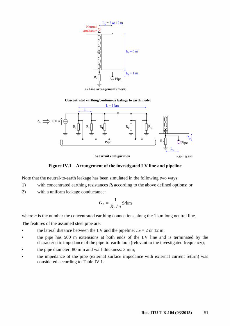
Rec. ITU-T K.104 (03/2015) 51
Figure IV.1 – Arrangement of the investigated LV line and pipeline
Note that the neutral-to-earth leakage has been simulated in the following two ways:
1) with concentrated earthing resistances Rf according to the above defined options; or
2) with a uniform leakage conductance:
S/km
where n is the number the concentrated earthing connections along the 1 km long neutral line.
The features of the assumed steel pipe are:
• the lateral distance between the LV and the pipeline: LP = 2 or 12 m;
• the pipe has 500 m extensions at both ends of the LV line and is terminated by the
characteristic impedance of the pipe-to-earth loop (relevant to the investigated frequency);
• the pipe diameter: 80 mm and wall-thickness: 3 mm;
• the impedance of the pipe (external surface impedance with external current return) was
considered according to Table IV.1.
nRG
f
f/
1

52 Rec. ITU-T K.104 (03/2015)
Table IV.1 – Measured external surface impedance of steel pipe
f
[Hz]
Zkk
[Ω/km]
[degree]
Rkk
[Ω/km]
Xkk
[Ω/km]
40 0.369 25 0.334 0.156
50 0.403 31.8 0.343 0.213
82 0.520 40.1 0.398 0.335
179 0.842 46 0.585 0.605
278 1.072 45 0.758 0.758
391 1.273 45 0.900 0.900
475 1.399 45 0.989 0.989
579 1.536 44.6 1.094 1.078
781 1.786 44 1.285 1.241
979 2.000 45 1.414 1.414
1482 2.471 46 1.716 1.777
1973 2.842 47 1.938 2.078
2474 3.196 48 2.139 2.375
2975 3.509 49 2.302 2.648
3979 4.067 52 2.504 3.205
4991 4.561 52 2.808 3.594
5989 5.010 52 3.084 3.948
6969 5.391 53 3.245 4.306
7977 5.777 54 3.395 4.673
The calculations have been performed for all of the above options (6 4 = 24 for each of the three Lt
options, i.e., total of 24 3 = 72) for the following frequencies:
Frequencies considered in the simulation calculations and site measurements
40 50 65 79 179 279 379 579 979 1979 2979 3979 4979 5979 6979 7979
IV.2 Feeding of the neutral-to-earth loop
The simulation calculations have been performed for the condition of 100 A current being injected
into the neutral-to-earth loop at the MV/LV transformer station end.
This type of injection has the advantage that the neutral voltages obtained can easily be recalculated
to any other (fault) current value.
Furthermore, the input impedance of the neutral is simply given as the input voltage divided by 100 A.
IV.3 Voltage and current profiles vs. length of the neutral
The voltage and current profiles vs. length figures have been drawn for all calculated options. These
are reproduced for a few representative cases which reflect the main tendencies.
The profile curves drawn with solid lines show the results obtained by simulation with discrete
earthing resistances, while those drawn with dotted lines show the results obtained by the simulation
by the uniform leakage Gf.

Rec. ITU-T K.104 (03/2015) 53
The curves marked with different colours are related to the following Lt with discrete earthing
distances:
The first group of figures shows the profiles for f = 50 Hz, Lp = 2 m with not-connected pipe
(Figures IV.2 and IV.3) and connected pipe (Figures IV.4 and IV.5) considering termination
resistance of RE = 0.5 is infinite, respectively.
The voltage and current profiles vs. length are plotted for a higher frequency (1'980 Hz) and also for
cases with not-connected pipe and connected pipe, shown in Figures IV.6 and IV.7, respectively.
The classification of these figures is given in Table IV.2.
Table IV.2 – Classification of the figures showing the voltage and current profiles
of the LV neutral conductors
Frequency
9 Hz
Condition for the connection with pipeline
Not connected Connected
Terminating resistance Ω Terminating resistance Ω
0.5 0.5
50 Figure IV.2 Figure IV.3 Figure IV.4 Figure IV.5
1'980 – Figure IV.6 – Figure IV.7
The following main tendencies can be observed from the voltage profile of the neutral of the neutral
conductor:
• the transferred voltage decreases with decreasing earthing resistance Rf and with shorter
spans between earthing electrodes;
• the connections to the pipeline reduce the transferred voltage, roughly speaking, by 50 per
cent;
• the connection of the neutral at the feeding boundary reduces the transferred voltage,
especially when Rf is high;
• the difference between voltages calculated by discrete Rf (real condition) and by distributed
leakage Gf is higher for smaller Rf and lower for shorter spans between earthing electrodes.
The attenuation with the length of the transferred voltage is much quicker for this higher frequency
especially for smaller Rf values and pipe connected cases. This is due to the change (decrease) in the
length constant of the neutral-to-earth loop.

54 Rec. ITU-T K.104 (03/2015)
a) Rf = 3
b) Rf = 30
c) Rf = 300
Figure IV.2 – Voltage and current profiles of the neutral vs. length,
not connected to pipeline, f = 50 Hz, Re = 0.5 , LP = 2 m

Rec. ITU-T K.104 (03/2015) 55
a) Rf = 3
b) Rf = 30
c) Rf = 300
Figure IV.3 – Voltage and current profiles of the neutral vs. length,
not connected to pipeline, f = 50 Hz, Re = inf., LP = 2 m
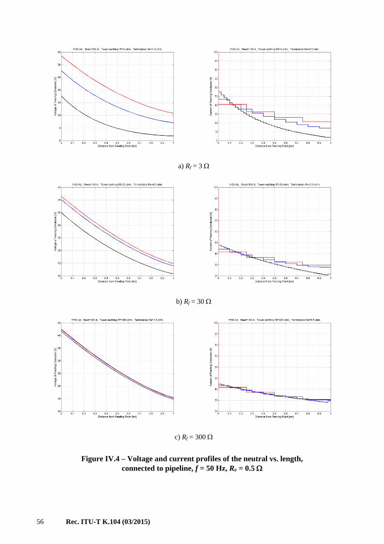
56 Rec. ITU-T K.104 (03/2015)
a) Rf = 3
b) Rf = 30
c) Rf = 300
Figure IV.4 – Voltage and current profiles of the neutral vs. length,
connected to pipeline, f = 50 Hz, Re = 0.5

Rec. ITU-T K.104 (03/2015) 57
a) Rf = 3
b) Rf = 30
c) Rf = 300
Figure IV.5 – Voltage and current profiles of the neutral vs. length,
connected to pipeline, f = 50 Hz, Re = inf.
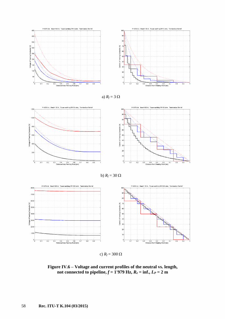
58 Rec. ITU-T K.104 (03/2015)
a) Rf = 3
b) Rf = 30
c) Rf = 300
Figure IV.6 – Voltage and current profiles of the neutral vs. length,
not connected to pipeline, f = 1'979 Hz, Re = inf., LP = 2 m

Rec. ITU-T K.104 (03/2015) 59
a) Rf = 3
b) Rf = 30
c) Rf = 300
Figure IV.7 – Voltage and current profiles of the neutral vs. length,
connected to pipeline, f = 1'979 Hz, Re = inf., LP = 2 m

60 Rec. ITU-T K.104 (03/2015)
Appendix V
Input impedance of the LV neutral-to-earth loop
(This appendix does not form an integral part of this Recommendation.)
NOTE – This appendix is based on [b-Cigre Guide].
Input impedance of the LV neutral-to-earth loop has been calculated according to the modelling,
options and parameters described in clause 4.
A survey of the values (modulus and phase) of the power frequency (50 Hz) input impedance of the
neutral-to-earth loop is given in Table V.1. These values are given for the options of the two key
parameters, i.e., the distance Lt between the subsequent discrete earthing locations and the resistance
Rf of discrete earthing structures. The effect of the terminating resistance Re representing the possible
continuation of the neutral is also demonstrated.
The relative importance of the different parameters can be more easily identified on the basis of the
bar diagrams shown in Figure V.1.
For the value of the input impedance the following main conclusions can be stated:
• input impedance value can vary in a wide range, i.e., between 0.25 to 74 ;
• the increase of Rf by an order of magnitude causes an increase of the input impedance by a
factor of two;
• the input impedance increases nearly proportionally with the distance Lt between the discrete
earthing if the neutral has no extension;
• the presence or absence of the terminating resistance Re is important in the case of a poor
earthing condition of the neutral section under study;
• the steel pipe effectively reduces (by factor two or even greater extent) the input impedance
only in the case where the neutral and the pipe are metallically connected (TN system).
When the neutral conductor is terminated at the feeding boundary (i.e., Re is infinite) and the neutral
has no metallic connection to the pipeline, the input impedance increases in the following extent,
depending on the value of the earthing resistance Rf and frequency:
• for small resistance (Rf = 3 Ω) 2-3 times increase, depending on the frequency;
• for medium resistance (Rf = 30 Ω) 3-15 depending on the frequency;
• for high resistance (Rf = 300 Ω) 15-150 times increase, increase depending on the frequency.
Therefore, the neutral termination has a special importance in the case of high resistance earthing
and/or its rare application.

Rec. ITU-T K.104 (03/2015) 61
Table V.1 – Input impedance of the neutral-to-earth loop for f = 50 Hz, Re = 0.5 Ω
Distance
between
discrete
earthling
Lt
[m]
Resistance
of discrete
earthing
(Rf)
[Ω]
Terminating
resistance
(Re)
[Ω]
Conditions for the steel pipe connection
Connected
(c)
Separated
(s)
Without pipe
(wo)
Zin
[Ω] Phase
degree
Zin
[Ω]
Phase
degree
Zin
[Ω]
Phase
degree
25
3 0.5 0.176 32.05 0.236 30.46 0.238 30.86
inf 0.175 32.00 0.235 30.41 0.237 30.85
30 0.5 0.350 33.71 0.682 32.23 0.688 33.26
inf 0.370 28.24 0.903 13.66 0.902 14.06
300 0.5 0.416 35.59 1.051 37.7 1.055 39.02
inf 0.481 28.83 7.623 1.71 7.620 1.75
100
3 0.5 0.276 31.37 0.442 28.76 0.446 29.51
inf 0.278 28.09 0.453 21.46 0.454 22.04
30 0.5 0.401 34.97 0.951 35.57 0.956 36.81
inf 0.457 28.13 3.114 3.68 3.112 3.77
300 0.5 0.423 35.84 1.104 38.65 1.108 40
inf 0.498 28.88 30.106 0.38 30.103 0.39
250
3 0.5 0.335 31.61 0.628 28.26 0.633 29.16
inf 0.359 25.53 0.851 9.61 0.850 9.86
30 0.5 0.414 35.38 1.040 36.99 1.045 38.29
inf 0.490 28.16 7.583 1.17 7.581 1.2
300 0.5 0.424 35.92 1.115 38.85 1.119 40.22
inf 0.51 28.71 75.081 0.11 75.079 0.11
a) Neutral continued at section boundary, represented by Re = 0.5 Ω

62 Rec. ITU-T K.104 (03/2015)
b) Neutral continued at section boundary, represented by the
characteristic impedance of the neutral conductor-to-earth circuit
c) Neutral separated at section boundary
Figure V.1 – Input impedance Zin of the neutral-to-earth loop at 50 Hz for
different earthing resistances, distance between the earthing electrode locations and
different conditions regarding the pipe: no bonding (Zbe_ö), neutral and
pipe isolated (Zbe_sz) or no pipe at all (Zbe_n)

Rec. ITU-T K.104 (03/2015) 63
Appendix VI
EPR due to a double earth fault in an MV distribution network
without a solidly-earthed neutral
(This appendix does not form an integral part of this Recommendation.)
NOTE – This appendix is based on [b-Cigre Guide].
This appendix is focused on the EPR occurring in MV/LV transformer stations when double earth
faults occur in an MV distribution network with a non-solidly-earthed neutral (i.e., networks with
earthing through an arc suppression (Petersen) coil or those earthed through a high resistance (25 to
100 ), both of which are common in Europe). The EPR of the MV/LV transformer station could be
transferred to the LV network through the neutrals of TN or TT system earthing of the LV network.
VI.1 Problem identification
1) Network condition
In the case of an MV distribution system an HV/MV transformer station feeds a group of MV lines
(typically 10 to 30 kV). The lines are assumed to be in a ring-type configuration, however the rings
are open at one point, so the network is operated as a radial system. The networks are typically
composed of underground cables in urban areas, a mixture of cable and overhead lines in suburban
areas and overhead lines in rural areas.
The MV cable network of an urban area is illustrated in Figure VI.1.
Figure VI.1 – Illustration of an MV cable network fed from an HV/MV transformer station
The network is a mixture of:
• older, lead-sheathed, steel-armoured cables, directly laid in the soil (with type code ended by
"VB") where they reduce the overall earthing resistances of both the HV/MV and MV/LV
transformer stations;

64 Rec. ITU-T K.104 (03/2015)
• newer, plastic-jacketed cables – the sheath/screen of which are earthed only in the
substations.
Older MV cables tend to decrease over time, as these cables are replaced with newer cables, causing
an increase in the overall earthing resistances of the stations. Similar tendency apply to the LV cables.
2) Frequency of the occurrence of double earth faults
In the case of an HV power system with solidly-earthed neutrals the phase-to-earth short-circuit level
should be considered when examining the induction to telecom lines, because this fault is considered
as a high probability event. The "high probability" event is correct in the sense that more than 95 per
cent of the faults are phase-to-earth faults in networks with a directly earthed neutral.
In the case of an MV distribution system with no solidly-earthed neutrals, the frequency per km and
year, of phase-to-earth faults is higher by about two orders of magnitude than that of an HV system
with solidly-earthed neutrals. However, the magnitude of the fault current caused by a single earth
fault is low, thus its short-term induction effect usually does need not to be considered. On the other
hand, about 5 per cent of single earth faults create double earth faults, i.e., one phase-to-earth fault at
a given location and simultaneously another phase-to-earth fault in another phase at another location
(see Figure VI.2)3. However, due to the large number of MV networks compared to HV networks,
the number of double earth faults on MV networks could, in practice, be up to 5 to 10 times higher
than the number of single earth faults occurring on HV networks. The double earth fault is a short-
circuit fault resulting in earth-return (zero sequence) current along the lines between the two faulty
points. The double earth fault current can cause significant induction effects along the faulty sections
and EPR at the fault locations (generally in transformer stations).
VI.2 Study of the relative importance of the network parameters and conditions
For the identification of the relative importance of the different parameters, simulation studies have
been carried out using the following parameter sets:
1) short-circuit power of the network. Essentially determined by the HV/MV (120/10.5 kV)
transformer, rated power (31.5 MVA) and short-circuit impedance (18 per cent);
2) earthing resistance of the grid of the HV/MV transformer station
(Rf120 = 0.3 );
3) earthing resistance of the earth grid of the MV/LV transformer station
(Rf10 = 2 or 0.2 );
4) sheath resistance of the MV cables
(Rk10 = 0.84 0.6 0.2 /km);
5) resistance at the fault points (e.g., arc resistance)
(Rh = 1 or 10 );
6) distance of the faulty points
• from the feeding points:
(Li = 0.2 0.6 1.8…5.4 km)
• from one another:
(L1-2 = 0.6 km);
7) sheath-to-earth leakage conductance
____________________ 3 A German utility (PESAG) notes that 30 per cent of faults are double earth faults on an 80 per cent
underground MV system with compensated neutral (NMT95). 4 Rounded value of the actual 0.75 /km.

Rec. ITU-T K.104 (03/2015) 65
(G = 0 0.05 1.0 S/km).
NOTE – The values in brackets have been used in the parametric study.
The investigated network arrangement and the some of the key parameters are shown in Figure VI.2.
Figure VI.2 – Double earth fault, one in the HV/MV and the other in the MV/LV station
The fault currents and sheath currents due to the double earth fault are plotted in Figure VI.3.
The EPR of the HV and MV stations are plotted for the above set of parameters in Figure VI.4.
VI.3 Main conclusions
The main conclusions drawn from the parameter study are as follows:
• the EPR occurring in the MV station is significantly higher than the EPR in the HV station;
• the EPR significantly increases with an increase of the earthing resistance of the MV/LV
station. Increases in the earthing resistance of the MV/LV stations can occur due to:
– smaller leakage to earth of the cables (fewer older lead-sheathed cables);
– bigger earthing resistances at the customer’s premise (fewer metallic tubes used for
water, gas supply systems);
• the EPR increases with the increase of the resistance of the sheath (i.e., due to the use of a
thinner screen);
• the EPR increases with the length of the cable to the faulty point up to a certain distance
(about 2 km) and then it tends to decrease;
• the EPR could decrease significantly with the increase of a fault resistance (e.g., resistance
of the arc), which is not a controllable parameter. This change is caused by the change in the
magnitude of the fault current (see Figure VI.4).

66 Rec. ITU-T K.104 (03/2015)
Figure VI.3 – EPR of the HV and MV substation grids due to double earth fault

67 Rec. ITU-T K.104 (03/2015)
Figure VI.4 – Fault and sheath current due to double earth fault

68 Rec. ITU-T K.104 (03/2015)
Appendix VII
Screening factor of a power cable with an imperfectly earthed sheath
(This appendix does not form an integral part of this Recommendation.)
VII.1 Criterion for long cables
For cables with continuously earthed sheath, the criterion for long cables is:
L >> 6 (VII.1)
where L is the length of the cable and is the length constant of the sheath-to-earth loop (see equations
(4) to (6)). Under this condition, i.e., in the case of long (in principle infinite) cable lines the current
induced in the sheath-to-earth loop is uniform; the current in the screening conductor and earth can
be expressed by equation (2) and equation (3) respectively with the screening factor ks given by
equation (4). In real lines, the values calculated by the screening factor are relevant only to the steady
middle section of the line.
For cables with insulating covers, the criterion for long cables is:
zsL >> Za + Zb (VII.2)
where zs is the impedance of the sheath-to-earth loop (see equation (3)), per unit length, Za and Zb are
the impedances/resistances to earth at the ends of the cable sections (see Figure VII.1).
VII.2 Short (finite length) cable sheaths with continuous earthing
When the criterion (VII.1) is not fulfilled for a cable sheath with continuous earthing, i.e., the cable
is short then the screening current continuously changes along the length, and it is affected by the
discrete earthing impedances at the line ends, thus the screening action cannot be expressed by the
screening factor any more. As a consequence, the EPR calculation based on the use of the screening
factor of the in-feeding power lines (see clause A.2.3) cannot be applied.
In his case the sheath-to-earth loop circuit should be solved, by considering its actual conditions. The
current and voltage results vs. length, provide the relevant information on the screening effect and
potential of the screening conductor and the EPR of earthing connected to it.
Analytical expressions are contained for the particular case when the sheath/screening conductor is
affected by uniform induced emf. See ITU-T Directives Vol. II clause 4.3.7, [ITU-T K.26].
VII.3 Screening factor of a power cable with an insulating cover
When a cable sheath/screen has an insulating cover it can be earthed with discrete earthing applied at
different locations. In the followings, the screening factor is specified for short cable sections earthed
only at the ends of the sections. In this case, the screening factor is not an intrinsic characteristic of
the cable because it is affected by the impedance of the applied earthing and distinction should be
made between the screening factor related to the sheath or to the earth.
The scheme and circuit representation of a short power cable sheath covered by an insulating jacket
and terminated with discrete earthing is shown in Figure VII.1 (see ITU-T Directives Vol. II
clause 4.3.7.4, [ITU-T K.26]). The figure shows the possible earth fault options, i.e., fault to the
sheath (to the sheath connected earthing system) at the a end (sa) or b end (sb) or to the earth at the
earth in the overhead line in the side a (ea) or in that of in the side b (eb). The switches in the equivalent
circuit should be positioned according to the fault location. Thus, the equivalent circuit can be
adjusted according to the possible four earth fault options.

Rec. ITU-T K.104 (03/2015) 69
Figure VII.1 – Scheme and circuit representation of a power cable sheath covered by
insulating jacket and terminated with discrete earthing
The position of the switches shown by solid lines corresponds to the case when both faults (Sa and
Sb) of a double earth fault are to the sheath. In this case, the screening factor is the one related to the
sheath. The position of the switches shown by broken lines corresponds to the case when both faults
of a double earth fault occur on the overhead lines. In this case, the screening factor is the one related
to the earth. Mixed fault locations are also possible, i.e., when one fault is on the overhead line (OHL)
and thus is earth related, while the other fault occurs in the cable section and thus is sheath related.
The following circuit elements are shown in Figure VII.1b:
Rs resistance of the sheath, per unit length
ZE external impedance of the sheath-to-earth loop obtained according to equation (3), per unit
length
ZA additional impedance due to the steel armoring, if applied, per unit length
L the length of the in the same unit as used in the per unit impedance
Ra (Za) resistance (impedance) to earth at the a end of the cable section
Rb (Zb) resistance (impedance) to earth at the b end of the cable section
3I0 zero sequence component of the fault current
IE earth current along the cable section
3IS the sheath current
ks = IE/3IS is the screening factor of the sheath.
The earth current and thus the screening factor ks of the sheath can be expressed by the current share
rule applied to the circuit representation shown in Figure VII.1b. In fact, this is the fraction of the
earth current given as the ratio of the impedance of the upper branch of the circuit to the total
impedance of the sheath-to-earth loop. The impedance of the upper branch should be varied according
to the fault locations represented by the position of the switches.

70 Rec. ITU-T K.104 (03/2015)
The screening factor for the possible four fault position locations are given by the following
expressions:
• sheath related at both sides:
(VII.3)
• earth related at both sides:
(VII.4)
• earth related at the side a and sheath related at the side b:
(VII.5)
• sheath related at the side a and sheath related at the side b:
(VII.6)
It is recognized that the impedance to earth improves the screening factor related to the sheath and
worsens the screening factor related to the earth. When any of the earthing impedance becomes
infinitive (unearthing) the screening factor related to the sheath becomes zero, i.e., perfect screening,
while the screening factor related to the earth becomes one, i.e., not screening at all.
VII.4 Screening factors for non-uniform lines
In power systems with solidly-earthed neutrals one phase-to-earth, short-circuit causes high fault
currents. In this case the 3I0 current is circulating between the fault location and the feeding point(s).
The OHL of a power system with a solidly-earthed neutral has earth wire or multi earthed neutral
which is connected to the cable sheath and to the earthing of the tower at the OHL to cable transition.
Such a situation is shown and an equivalent circuit supporting an approximate solution can be found
by referring to Figure I.6. Due to the difference in the screening factor ks,OHL of the earth wire and the
screening factor ks,C of the cable sheath there is a difference in the screening currents of magnitude
(ks,OHL – ks,C) 3I0. This is an additional current source/sink point at the transition point between the
cable and the overhead line. The majority of this current is passing through the tower earthing at the
transition point that can lead to a significant EPR which may exceed the EPR caused by the same 3I0
in the substation.
For non-uniform lines, where the type or number of earth wires change or the relative position
between the earth wires and phase conductors' changes (at the locations of phase transposition) such
that the earth wire screening factor changes also represents another earth current source point that can
lead to an EPR.
basAE
sSSs
RRLRZZ
LRk
)(, =
3 0
E
I
I
basAE
basEEs
RRLRZZ
RRLRk
)(, =
3 0
E
I
I
basAE
asESs
RRLRZZ
RLRk
)(, =
3 0
E
I
I
basAE
bsSEs
RRLRZZ
RLRk
)(, =
3 0
E
I
I

Rec. ITU-T K.104 (03/2015) 71
Appendix VIII
Screening factors of telecommunication cables with
imperfectly earthed sheaths
(This appendix does not form an integral part of this Recommendation.)
To distinguish the telecommunication cables of long and short length, the same criterion applies as
with power cables i.e., cables with continuously earthed sheaths – equation (VII.1) and cables with
insulating covers – equation (VII.2). In the following the screening factors are considered for
telecommunication cables with insulating covers for two induction options.
VIII.1 Telecommunication cables affected by longitudinal induction
The screening factor of a telecommunication cable is given for the following conditions:
• the cable sheath has an insulating cover;
• the sheath is earthed at the A and B ends by discrete impedances;
• the length of the cable is l km;
• the sheath-to-earth loop is affected by longitudinal induction causing total longitudinal emf
of:
(VIII.1)
Under these conditions four longitudinal voltages can be distinguished as shown in Figure VIII.1:
Figure VIII.1 – Longitudinal voltages with respect to different references
Using the coaxial hypothesis, the longitudinal voltages, by consideration of the screening action of
the sheath, can be expressed with the following screening current:
(VIII.2)
where: Rs is the sheath resistance, Za is additional impedance due to steel armor; Ze is the external
impedance of the sheath with earth return, all in /km, ZA and ZB are the earthing impedances at the
ends of the cable, in .
The longitudinal voltage measured to the sheath at the end A on the conductor (blue) connected to
the sheath at the end B (see Figure VIII.2) is given by:
k kl ElEE
BAeas
k
k
SZZZZRl
E
I

72 Rec. ITU-T K.104 (03/2015)
(VIII.3)
Figure VIII.2 – Longitudinal voltages related to the sheath at both ends
The screening factor kSS related to the sheath at both ends is obtained by applying the definition
expression and substituting USS as follows:
(VIII.4)
Similarly, the longitudinal voltage measured to the earth at the end A on the conductor (green)
connected to the earth at the end B (see Figure VIII.3) is given by:
(VIII.5)
Figure VIII.3 – Longitudinal voltages related to the sheath at both ends
The screening factor kEE related to the earth at both ends is obtained by applying the definition
expression and substituting UEE as follows:
(VIII.6)
The screening factor kES related to the earth at the A end and to the sheath at the B end can be derived
from the UES voltage (purple conductor) as follows:
k
k
BAeas
s
ssSS EZZZZRl
RlIRlU
BAEaS
S
k
k
SSSS
ZZZZRl
Rl
E
Uk
k
k
BAeas
BAsSBAsEE E
ZZZZRl
ZZRlIZZRlU
)()(
BAEaS
BAS
k
k
EEEE
ZZZZRl
ZZRl
E
Uk

Rec. ITU-T K.104 (03/2015) 73
(VIII.7)
Finally the screening factor kSE related to the sheath at the A end and to the earth at the B end can be
derived from the USE voltage (red conductor) as follows:
(VIII.8)
VIII.2 Telecommunication cables affected by EPR
This clause discusses the particular screening effect of a telecommunication cable screen connected
to earthing which is affected by EPR (Figure VIII.4).
The telecommunication cable enters the EPR zone and its sheath/screen is connected to the earthing
system affected by the EPR. The EPR zone can be e.g., an MV/LV transformer station including the
earthing system of those nearby consumers to which the EPR is – totally or partly – transferred
through the neutral conductor of a TN system. It is assumed that the screened telecom cable has an
insulating covering. In the telecom site the sheath is bonded to the earthing system of the site (to the
MET, see Figure 16). Therefore, the longitudinal voltage, Ust transferred to this site is related to the
sheath. However, if there is an unscreened extension of the telecom line, the longitudinal voltage Uet
in the site of this extension is earth related.
Figure VIII.4 – Arrangement of telecommunication cable affected by EPR
The screening factors relevant to the described situations can be determined in the same steps as
described in the previous clause, however the affecting source is a discrete voltage source
representing the EPR.
NOTE – The reaction of the telecom screen to the EPR magnitude is neglected.
The current IS in the telecom sheath-to-earth loop is given by the following equation:
(VIII.9)
where: Rs is the sheath resistance, Za is additional impedance due to steel armor (if applied); Ze is the
external impedance of the sheath with earth return, all in /km; RT (may be ZT) is the earthing
resistance (impedance) at the telecommunication site, in .
BAEaS
AS
k
k
SSES
ZZZZRl
ZRl
E
Uk
BAEaS
BS
k
k
SESE
ZZZZRl
ZRl
E
Uk
Teas
EPRS
ZZZRl
UI

74 Rec. ITU-T K.104 (03/2015)
The longitudinal voltage Ust measured to the sheath and relevant to the sheath-connected telecom site
(see Figure VIII.4) is given by:
(VIII.10)
The screening factor related to the sheath and relevant to the sheath-connected telecom site is given
as:
(VIII.11)
The longitudinal voltage Uet measured to the earth and relevant to the unscreened – extension-
connected telecom site (see Figure VIII.4) is given by:
(VIII.12)
The screening factor related to the earth and relevant to the unscreened – extension-connected telecom
site is given as:
(VIII.13)
Finally, the voltage UT transferred to the earthing system of the telecom site over the sheath of the
telecom cable is given by the following expression:
(VIII.14)
EPR
Teas
sssst U
RZZRl
RlIRlU
Teas
sst
RZZRl
Rlk
EPR
Teas
Tssset U
RZZRl
RRlIRlU
Teas
Tset
RZZRl
RRlk
EPR
Teas
TsTT U
RZZRl
RIRU

Rec. ITU-T K.104 (03/2015) 75
Bibliography
[b-ITU-T K.9] Recommendation ITU-T K.9 (1988), Protection of telecommunication
staff and plant against a large earth potential due to a neighbouring
electric traction line.
[b-ITU-T K.73] Recommendation ITU-T K.73 (2008), Shielding and bonding for cables
between buildings.
[b-IEC 61643-11] IEC 61643-11 (2011), Low-voltage surge protective devices – Part 11:
Surge protective devices connected to low-voltage power systems –
Requirements and test methods.
[b-IEC 61643-12] IEC 61643-12 (2008), Low-voltage surge protective devices – Part 12:
Surge protective devices connected to low-voltage power distribution
systems – Selection and application principles.
[b-Cahier172] Lacroix, B. and Calvas, R. (2004), System earthings in LV, Cahier
Technique, No 172, December.
[b-Cahier173] Lacroix, B. and Calvas, R. (1995), Earthing systems worldwide and
evolutions, Cahier Technique, No173, September.
[b-CDEGS] Safe Engineering Services & Technologies Ltd., Current Distribution,
Electromagnetic Fields, Grounding and Soil Structure Analysis (CDEGS),
Software package manuals, Montreal, Quebec, Canada, Application
Version 13.
[b-Cigre Guide] Cigré Joint Working Group C4.207 (2014), Guide for assessment of
transferred EPR on telecommunication systems due to faults in A.C. Power
systems, Technical Brochure 592.
[b-Cigre Protection] Cigré Joint Working Group C4.202 (2005), Protection Measures for Radio
Base Stations sited on Power Line Towers, Technical brochure 266.
[b-Electropedia] IEC 60050-Series, International Electrotechnical Vocabulary. http://www.electropedia.org
[b-Endrenyi] Endrenyi, J. (1967), Analysis of Transmission Tower Potentials During
Ground Faults, IEEE Transactions on Power Apparatus and Systems,
Vol. 86, No. 10, October, pp. 1274-1283.
[b-Grcev] Grcev, L. (2001), Modelling of grounding systems for better protection of
communication installations against effects from electric power system and
lightning, INTELEC 2001, pp. 461-468.
[b-Paul] Paul, C. R. (1994), Analysis of Multiconductor Transmission Lines, John
Wiley & Sons, New York.
[b-Rajotte] Rajotte, Y. (2005), Earth potential rise influence near HV substations in
rural areas, CIRED, session 2, June, pp. 1-4.
[b-Sollerkvist] Sollerkvist, F. J. and Varju, Gy. (1995), A general model and numerical
method for multiconductor systems in frequency domain. IEEE/KTH
Stockholm Power Tech. Conference. Stockholm, Sweden, June 18-22,
1995, pp. 227-232.
[b-Terms] Standard Dictionary of Electrical and Electronics Terms (1997), 6th
edition, IEEE.


Printed in Switzerland Geneva, 2015
SERIES OF ITU-T RECOMMENDATIONS
Series A Organization of the work of ITU-T
Series D General tariff principles
Series E Overall network operation, telephone service, service operation and human factors
Series F Non-telephone telecommunication services
Series G Transmission systems and media, digital systems and networks
Series H Audiovisual and multimedia systems
Series I Integrated services digital network
Series J Cable networks and transmission of television, sound programme and other multimedia
signals
Series K Protection against interference
Series L Environment and ICTs, climate change, e-waste, energy efficiency; construction, installation
and protection of cables and other elements of outside plant
Series M Telecommunication management, including TMN and network maintenance
Series N Maintenance: international sound programme and television transmission circuits
Series O Specifications of measuring equipment
Series P Terminals and subjective and objective assessment methods
Series Q Switching and signalling
Series R Telegraph transmission
Series S Telegraph services terminal equipment
Series T Terminals for telematic services
Series U Telegraph switching
Series V Data communication over the telephone network
Series X Data networks, open system communications and security
Series Y Global information infrastructure, Internet protocol aspects and next-generation networks
Series Z Languages and general software aspects for telecommunication systems