Embed Size (px)
Citation preview

®
INSTALLATION MANUAL
EXPANDABLE MULTIFUNCTION CONTROL PANEL
KYO 320
ISO 140019191.BNT2
ISO 14001IT-52588
ISO 90019105.BNT1
ISO 9001IT-52587

This system can be programmed using the respective KYO320 Software Application 2.0 or higher.
Installation of the system must be carried out strictly in accordance with the instructions described in this manual, and in
compliance with the local laws and bylaws in force.
The KYO320 Control panels have been designed and manufactured to the highest standards of quality and performance.
The KYO320 Control panels have no user-friendly components, therefore, should be serviced by authorized personnel only.
BENTEL SECURITY shall not assume the responsibility for damage arising from improper application or use.
The manufacturer recommends that the installed system should be completely tested at least once a month.
Hereby, Bentel Security, declares that KYO320 Control panels comply with the essential requirements and other relevant
provisions of Directive 1999/5/EC.
BENTEL SECURITY srl. reserves the right to change the technical specifications of this product without prior notice.
BENTEL SECURITY s.r.l.
Via Gabbiano, 22- Zona Ind. S. Scolastica
64013 Corropoli (TE) - ITALY
Tel.: +39 0861 839060
Fax: +39 0861 839065
e-mail: [email protected]
http://www.bentelsecurity.com
2
®
TABLE OF CONTENTS
INTRODUCTION 5About the System 5
General Features 6
The System and Accessories 6
Technical Specifications 7
Accessory Items 8KYO 320 features Table 8
IDENTIFICATION OF PARTS 9About the Control panel 9MIA-D and ALISON-DVP Keypads 11
Note about Switching Power Supply 11
Readers and Digital Keys 13Input and Output Expanders 14
INSTALLING 15Mounting the Main Unit 15
Connecting Keypads 15Connecting Readers 16Connecting Input and Output Expanders 16
Terminals 17
Main Unit 17BPI Peripherals 18
Wiring 18
Connecting BPI Bus Devices 19
BPI bus Wiring Limitations 21Connecting Detectors 22
Connecting Motion Detectors 23Glass Break Detectors 24Connecting Roller-Blind and Vibration Detectors 24Connecting Fire Detectors 25
Connecting Alarm Signalling Devices 25
Supervised Outputs 26Connecting Tamper Terminals 27
Connecting the Telephone Line 28
Connecting a Power Supply 28
Connecting the Mains 29Auto-configuration 29RAM Battery (see page 11) 29Thermal Probe 29
PROGRAMMING 31Configuration (Enrolling Devices) 31
Keypads Page 32LED Keypads 32Input Expanders 32Output Expanders 32Readers 32
Power station 33Accessories 34
Hardwired Zones 35
Type 36Command 37Attributes 37Balance Type 38Threshold 39Inactivity 39Cycles 40Partitions 40Sensitivity 40Voice Messages 41
AND Mode Zones 41
VectorRX Wireless Receivers 41
Replacing Wireless Devices 43Enrolling Wireless Devices 43Unenrolling Wireless Devices 43
Outputs 43
Type 43Polarity 43Attributes 44Associated Timer 44Times 44Oscillation 45Cycles 45Events 45
Partitions 45
Telephone 47
Answer 47Dialling 47Answering Machine 48
Dialler 48
Dialler book 48Send Message after ... 49Messages 49Options 49Actions 49
Digital Communicator 50
Voice Messages 52
Compound Messages 53Teleservice 53
Enable Test Event 54Installer Maintenance 54Central Station Maintenance 55
Log – Events setup 55
Events-Actions 55
Telephone action priority 56Colours 56Events Details 56Clear 57Find 57
KYO320 3

Event Description 57Scheduler - Arming 71
Type Description 71Models 71Options 72Examples 72
Scheduler - Timers 73
Type Description 73Models 74
Options 74
Keypad Codes - User 76
Enable on Partitions 77Associated Timer 78User menu access 78Father PIN 78New PIN 78Code Type 78Enable on LCD Keypad 78Enable on LED Keypad 79Programming 79
Codes - Installers 79
Lost Installer Codes 79Codes - Code Types 80
User Codes 80Installer Codes 82
Digital keys 82
Allowed Operations 83Attributes 83Enable on Key Reader 83
KeyFobs 83
Clock 84
On-site downloading 84
Firmware Upgrade 85
Remote Downloading 85
Check Panel 87
APPENDIX 89K3/VOX2 Voice Board 89
Features 89Identification of Parts 89Installation 89Expanding Listen-in coverage 89Manual selection 90Auto-select mode 90Manual and Auto-select mode 91
K3/PRT2 Printer Interface 91
Identification of Parts 91Connecting the Printer 91Installation instructions 91
VectorRX, VRX32-433 and VectorRX-8 Receiver 92
Identification of Parts 92Choosing a Mounting Location 92Mounting the Receiver 93Connecting the Receiver 94Technical Specifications 94
B-NET MODULE 94
Identification of parts 94Mounting the B-NET Module 95Technical Specifications 95
Reset default 95
Reporting Formats 95
TELIM 95Contact ID 95SIA/SIA over B-NET 96
dbManager 96
Data Transfer 96Tools 97Copying Customer accounts 99
Difference between KYO300-100 (rev. 1.30) and
new KYO320 control panel 100
4

INTRODUCTION
About the System
The full-featured KYO320 security systems have been
especially designed to satisfy all security needs, from resi-dential to advanced industrial applications.
The objective of the KYO320 is to make end-user oper-ation simple and help the Installer improve efficiency.
This is achieved by reduced complexity software and
firmware, and remote programming and diagnostic fa-cilities.
This system provides impressive application flexibility
and many interesting features such as monitoring facili-ties and telephone access (refer to “Telephone func-tions”).
KYO 320 has 8 Input zones expandable to 344, and 6
Outputs expandable to 118.
Partitions KYO320 manages 32 independent Parti-tions — all with Stay/Away control. Each Partition
(group of zones) can be programmed with its own En-try/Exit and Auto-Arm/Disarm Times, etc., and can be
controlled by digital Keys/Cards, Codes and/or Input
zones.
Events and Actions KYO320 manages over 3000
events . The factory default settings have been purpose
programmed to require few or no changes for standard
applications. However, the programming flexibility of
the Events and Actions (Output, Digital communicator
and Voice Dialler Actions) will allow you to fully custom-ize the system.
Telephone Functions The Telephone Communicator
manages 50 telephone number. Up to 8 telephone
numbers can be assigned to the Digital Communicator.
Each Communicator number can have its own Cus-tomer Code and Reporting format (usually assigned by
the Central station).
The Bentel Security Suite Software and B-Mod Mo-dem (accessory items) reduce on-site time to a mini-mum by allowing you to provide Teleservice (on-line
Customer enquiry and assistance facilities).
The Teleservice function can also be used for up-loading, downloading and diagnosis. Up to 4 telephone
numbers can be assigned to this function.
Voice Board The K3/VOX2 Voice Board (accessory
item) manages 64 recordable Voice messages and 32
telephone numbers for the Answerphone, Dialler,
Memo and Ambient-sound recording facilities.
The answering device can function even if the K3/VOX2
Voice Board is absent, but in this case there aren't voice
messages.
Voice communications to and from the Control panel al-low operations such as: Listen-in; Talk/Listen-in (2Way
Audio); Input status enquiry (with Voice answer); Re-mote control of appliances (Turn ON/OFF); Arm/Disarm
Partitions; Alarm Reset and Inhibit Calls.
Access to all the “over-the-phone” features requires a
Telephone Access Code — which can be disabled im-mediately after use.
Scheduler The Scheduler can be setup to Arm/Disarm
Partitions automatically (on a daily or weekly basis),
and to control 64 daily timer events for KYO320.
Wireless Devices This system supports the
VectorRX, VRX32-433 and VectorRX-8 Receiver (ac-cessory item). The VectorRX and VRX32-433 Receiver
accepts up to 32 Wireless devices (64 with 2 VectorRX
or VRX32-433), such as: PIR Motion Detectors
(AMD10); Magnetic Contacts (AMC10); Glass break
Detectors; Smoke Detectors (ASD10), and up to 16
Wireless Keys (32 with 2 VectorRX or VRX32-433)
(KeyFob) (ARC20). VectorRX-8 Receiver accepts up to
8 Wireless devices and up to 8 Wireless Keys (KeyFob)
(ARC20).
Programming This system can be programmed from
the Keypad, or via the KYO320 Software Application
and a computer. The Software Application (runs under
Windows) provides real-time supervisory facilities (via
connection to an RS232 Interface or Teleservice), and
will allow you to make the fullest use of all the system
features.
KYO320 INTRODUCTION 5

General Features
The KYO320 Control panel
� Up to 344 Alarm zones: 8 zones on the Main Board;
192 on 32 Input Expanders (6 zones per expander);
64 on 32 MIA-D Keypads (2 zones per keypad); 16
on 16 ALISON/32LP LED Keypads (1 zone per key-pad) and 64 Wireless zones
� Up to 118 Outputs: 6 Outputs on the Main Board (3
Relays and 3 Open-Collectors); 96 on 16 Output Ex-panders (6 outputs per expander) and 16 on
ALISON/32LP LED Keypads
� Up to 32 backlit LCD Keypads for system control
� Up to 32 Digital Key/Card Readers
� 195 User Codes with programmable ‘View’ option,
priority and functions
� 10000 Event Log with date and time details
� Up to 8 power stations
� 4 wire Bus (protected against short-circuit) for pe-ripherals
� Dual branch bus for protection against tamper
� Programmable Balance, Operating mode and Alarm
type — for all zones
� Input zones can be programmed to send specific
commands to the Control panel
� Outputs can be programmed as bistable or cyclic
with programmable cycle times and standby status
� 32 programmable partitions — each with own zones,
keypads, readers, outputs and times
� 195 User Codes with programmable priority and
functions
� 500 programmable Digital Keys/Cards
� 16 character labels (ID) for the partitions, zones,
keypads, readers, codes, keys/cards, etc. — the as-signed label will be shown on the keypad display dur-ing the user operations
� 10000 Event Log — provides details of the operation
type, time and user
� RS232 Interface for system programming and moni-toring
� Software (runs under Windows) for Control panel
Programming, Teleservice and Monitoring
Telephone Facilities
� Pulse and Touch-tone (DTMF) dialling
� 50 Telephone numbers for Telemonitoring,
Teleservice and Voice Calls
� Integrated Digital Communicator: supports Pulse,
DTMF and FSK Reporting formats
� 6 Instant Alarm calls from each Keypad
� Programmable Test call
� Double Call
� Line sharing with other Telephone devices
� 1200 baud FSK integrated Modem for Teleservice
management
Telephone facilities with K3/VOX2 optional Voice Board
� Dialler function: sends recordable voice messages to
up to 32 Telephone numbers
� Remote Inquiry with Voice answer (requires Access
Code)
� Remote control of Outputs, Arm/Disarm operations,
Alarm Reset (requires Access Code)
� Remote Listen-in and multipoint Telephone commu-nication (Talk/Listen-in)
� Answerphone function
Scheduler function
� Daily, Weekly and Monthly scheduling
� Holiday and Daylight Saving (BST) changeover
management
� Overtime and Arming delay management
� 4 Arm and 4 Disarm operations per day per Partition
� 64 independent daily Timer events for KYO320.
Event print-out using optional K3/PRT2 Board
� Prints Events on parallel printer
� Real-time and/or Event Log printout from specified
date to last Event
� Event filter
The System and Accessories
The Control panel The Control panel is the core of the
system. It has 8-zones (KYO320 expands to 344); 6 Out-puts (KYO320 expands to 118;) and a 3A Switching Power
Supply (5A accessory item).
Expanders The Control panel manages up to 32 six
zone M-IN/6 Input Expanders and up to 16 M-OUT/6
Output Expanders (6 Open-Collector Outputs per Ex-pander).
Control Devices The KYO320 accepts up to 32
ECLIPSE and/or PROXI Digital Key/Card Readers
and/or 16 ALISON/32LP LED Keypads, and/or up to 32
MIA-D and/or ALISON-DVP LCD Keypads.
The operating principles of the ECLIPSE and PROXI
Readers are the same, except:
� ECLIPSE Readers accept SAT Keys only and are for
indoor use (unless mounted inside weatherproof
boxes);
� PROXI Readers have weather strips, and can be in-stalled indoors or outdoors (IP34 Protection Class)
and accept SAT Keys and PROXI-cards.
� ECLIPSE and PROXI Systems operate without con-tacts, therefore, are highly resistant to oxidization
and wear.
� Alison/32LP is a 32 LED Keypad with built-in pro-grammable Proximity Reader function.
The operating principles of the MIA-D and
ALISON-DVP Keypads are the same, except:
� MIA-D Keypads have larger displays, 2 on-board
zones and 3 sets of function keys for manual activa-
tion of Alarm status;
� ALISON-DVP Keypads have smaller cases, 1
on-board zone, an integrated Loudspeaker and Mi-crophone for use with the K3/VOX2 and built-in pro-grammable Proximity Reader function.
� ALISON-S(B029) is identical to ALISON-DVP but
DOES NOT have a microphone, loudspeaker and
built-in programmable Proximity Reader function.
6

� Unlike KYO300, the new KYO320 control panelsupports all Bentel LCD Keypads (Alison-S,Alison-DVP, Mia-D e Mia-S). The manufacturerrecommends to comply with following rules:1- the Keypad from 17 to 32 address must beMia-D and Alison-DVP type ONLY;2- if the number of BPI bus devices is greater than80, must be utilized Mia-D and Alison-DVP key-pad ONLY, otherwise the bus BPI bit rate goesdown.
K3/VOX2 The K3/VOX2 Voice board (accessory item)
can be used for Voice Messages, and Telephone Access.
K3/PRT2 The K3/PRT2 Printer Interface (accessory
item) can be used for real-time and/or Event Log print-out.
Power station The Power station has been especially
designed for Security system applications. The tamper
protected box (protected against delinquency and
forced removal) can house a backup battery for power
supply during black-out. This control panel supports up
to eight BXM12-B/30 3A Power Stations and/or
BXM12-B/50 5A Power stations.
Management Software The management software
(runs under Windows) provides full Programming, Cus-tomer Database and real-time Supervisory functions,
and will allow you to make the fullest use of all the sys-tem features.
The B-Mod Modem The B-Mod Modem will allow you
to Upload/Download from/to the remote system and
carry out Teleservice operations (remote diagnosis
and maintenance). The B-Mod/RX will allow you to Up-
load/Download from/to the remote system and carry
out Teleservice and Telemonitoring (send/receive
real-time transmissions).
Technical Specifications
The following table contains the technical Specifica-tions of the KYO320.
Voltage 230 V~ ±10% 50/60 Hz
Maximum current
draw0.9 A
Insulation Class Class I
Power
Supply/Battery
Charger
13.8 V_ ±1% 3 A (5A
accessory item)
Maximum Current
available for
Peripherals
1.8 A (3.8 A accessory item )
Battery
(Brand and Type)
12 V - 7 Ah or 12 V - 17 Ah
YUASA
NP 7-12 FR or NP 17-12 FR or
similar
Case Flame Class UL94-V2 or
higher
Random Digital
Key/Card Codes 4.295.000.000
Operating
Temperature 5 - 40 °C
Dimensions
(W x H x D)339 x 488 x 108 mm
Weight
(without battery) 5.55 Kg
The following chart shows the current draw (I (mA) col-
umn) and size of the accessory components.
ComponentI
(mA)
Size
(WxHxD mm)
KYO320 Main Board 250 —
MIA-D Keypad 50 164 x 133 x 44
ALISON-DVP andALISON-S(B029) Keypad
40 143 x 115 x 38
ECLIPSE Reader 30 —
PROXI Proximity Reader 30 78 x 108 x 22
ALISON/32LP LED Keypad 70 142 x 115 x 35
M-IN/6 Input Expander 20
108 x 101 x 34M-OUT/6 Output Expander 20
Omnia4R 4 Relay Module 120
K3/VOX2 + VOX-REM
Voice Board + Microphone-Loudspeaker Board
20 —
K3/PRT2 Printer Interface 40 —
BXM12-B/30 Power Station 10 —
BXM12-B/50 Power Station 10 —
VectorRX Receiver 50 146 x 290 x 28
KYO320 INTRODUCTION 7

� Accessory Items
The following chart shows the Control panel accessory
items, and certifications.
MIA-D Backlit LCD Keypad (2 Inputs)ALISON-DVP Backlit LCD Keypad (1 Input) with
Microphone + Loudspeaker+PROXIALISON-S(B029) Backlit LCD Keypad (1 Input) with-
out Microphone + LoudspeakerALISON/32LP 32 LED Keypad (1 Input and 1 Output)
M-IN/6 6 Input Expander ModuleM-OUT/6 6 Output Expander ModuleK3/VOX2 Voice BoardK3/PRT2 Printer Interface
VOX-REM Microphone + Loudspeaker forListen-in function
MINI-BOX Microphone + Loudspeaker boxPROXI Proximity Reader
PROXI-CARD Proximity CardECLIPSE3ABI Flush mounting, Contactless
Reader— AVE
ECLIPSE3AN Flush mounting, Contactless
Reader— AVE noir
ECLIPSE3DEL Flush mounting, Contactless
Reader— DELTA
ECLIPSE3DN Flush mounting, Contactless
Reader— DELTA noir
ECLIPSE3GE Flush mounting, Contactless
Reader— GEWISS
ECLIPSE3GGE Flush mounting, Contactless
Reader— GEWISS noir
ECLIPSE3GP Flush mounting, Contactless
Reader— GEWISS playbus
ECLIPSE3IN Flush mounting, Contactless
Reader— TICINO international
ECLIPSE3LGT Flush mounting, Contactless
Reader— TICINO light
ECLIPSE3MA Flush mounting, Contactless
Reader— TICINO magic
ECLIPSE3VI Flush mounting, Contactless
Reader— VIMAR idea
ECLIPSE3VIB Flush mounting, Contactless
Reader— VIMAR light
SAT Digital Key, Contactless—forKey and Proximity Readers
OMNIA/4R 4 relay Module for Output ExpandersBXM12-B/30 3 A Power StationBXM12-B/50 5 A Power Station
B-MOD Teleservice ModemB-MOD/RX TeleserviceandTelemonitoringModem
CVSER/9F9F Serial cable for computer linkADSER/9M25F 25 pin adapter for serial portsSECURITYSUITE Management SoftwareVECTOR/RX Wireless Receiver
VRX32-433 Wireless ReceiverVECTOR/RX-8 Wireless Receiver
AMD10 Wireless PIR DetectorAMC10 Wireless Magnetic ContactARC20 Wireless Digital KeyASD10 Wireless Smoke DetectorASNC Seize microswitch for Keypads
ASNC-MINI Seize microswitch for ProximityReaders
KST — Thermal Probe
� KYO 320 features Table
KYO 320
Readers 32
Expander-In 32
Expander-Out 16
Power Stations 8
LCD Keypads 32
LED Keypads 16
Compatible LCD Keypads
(MIA-D, ALISON-DV,
ALISON-S with firmware 1.30
or higher ONLY) ALISON-DVP
e ALISON-S (B029)
RX Wireless Receiver Yes
Zones on-board 8
Zones on Keypad 64+16
Zones on Exp-In 192
Wireless Zones 32+32
Total Zones 344
Supervised Relay Outputs 3
On-board Relay Outputs 3
Open-drain Outputs on-board 3
Open-drain Outputs on- Exp-out 96
Total Outputs 102+16
Partitions 32
Total User Codes 195
DTMF User Codes 64 (out of 195)
Installer Codes 5
User Code Types 16
Installer Code Types 3
Keys/Cards 500
Keyfobs (Wireless Keys) 16+16
Events in Log 10000
Total Events-Actions 3418
Customizable Events 32
Timers 64
Fuses 10
Voice Messages 64
K3/VOX2 Voice Board Yes
K3/PRT2 Printer Board Yes
Numbers in Phonebook 50
Telephone Dialler Actions 50
Digital Communicator Actions 100
8

IDENTIFICATION OF PARTS
Please read this section carefully to get an overall view
of the main components of the system and LEDs.
The numbers in boldface (used in this text) refer to the
descriptions in the tables and figures in this section.
The components are generally numbered in clockwise
order. The outlined numbers refer to the common hard-ware components of the BPI devices and are described
once only — when first encountered.
� About the Control panel
Figure 1 shows the maximum configuration of the
KYO320, therefore, some of the components may not
be present on this system.
KYO320 IDENTIFICATION OF PARTS 9
No. DESCRIPTION
1 Frontplate screws (2)2 Loudspeaker (supplied with K3/VOX2 Voice
Board)3 Tamper microswitch4 Main Board (see fig. 2)5 Backplate anchor screw locations (4x Ø 5 mm)6 K3/VOX2 Voice board (accessory item)7 K3/PRT2 Printer Interface (accessory item)8 Switching Power Supply (see fig. 3)9 Thermal probe (accessory item)
10 Housing for 12V – 17Ah max. Battery (not supplied)
11 Cable entry12 Seize microswitch13 Seize microswitch bracket14 Loudspeaker Connector15 Future use connector16 Terminal board for Telephone line connection17 K3/VOX2 Voice Board connector19 K3/PRT2 Printer Interface connector20 Flash Memory chip21 Memory Jumper (M) — if inserted, it will allow
the system to save the programmed parametersduring black-out:o//= parameters will be deleted (at default);//o = parameters will be saved
22 Switching power Supply connector (connected)23 RAM chip battery holder24 Serial Port RS23225 MICRO LED(RUN):
OFF or ON = Microprocessor blockedFlickering = Microprocessor OK
No. DESCRIPTION
26 BPI LED:OFF = BPI Bus OKON = BPI Bus Trouble
27 MAINS LED (POW):ON = Control panel powered by Mains (230 V);OFF = Mains Failure—the Control panel will bepowered by the backup Battery during blackout
28 RESET LED (RES):OFF = Microprocessor OKON = Microprocessor resetting
29 Self-recover termic Fuse30 Connector for backup Battery (The control panel
shuthdown the backup Battery due to voltagedrop (Safety threshold 9,6V), because this con-dition can damage the battery)
32 Terminal board (KEY BUS) for VectorRX,VRX32-433 and VectorRX-8 Receiver connec-tion
33 Terminal board (BPI bus) for BPI device connec-tions
34 Self-recover termic Fuse35 Self-recover termic Fuse36 Self-recover termic Fuse37 Self-recover termic Fuse38 connector for MIA-D, ALISON-DVP or Alison-S(B029)
Keypad39 Microprocessor40 Terminal board for Tamper Line and Input de-
vice connections (Detectors, etc.)41 Seize connector (connected)42 Self-recover termic Fuse43 Self-recover termic Fuse44 Self-recover termic Fuse45 Self-recover termic Fuse46 Self-recover termic Fuse47 RAM chip49 Terminal board for Output device connections
(Sirens, etc.)50 STOP ALARM Jumper: can be used to disable
Outputs no. 1, 2 and 3 (terminals +N1, +A1,C1-NC1-NA1, +N2, +A2, C2-NC2-NA2, +N3,+A3, C3-NC3-NA3)://o = Output Enabled (at default)o// = Output Disabled
51 Tamper microswitch connector (connected)53 Stranded wires: connect the Switching Power
Supply to the Main board (connected)54 Fine Adjustment Trimmer55 Auxiliary power terminals (13.8 V)56 Mains terminals
(230V / 50 Hz)

10
91
011
12
13
14
15
16
17
18
19
20
21
22
23
24
33 34 353231302928 36 37 38 39 40 41 42 43 44 45
59
60
61
46 49
62
666768 65 64
C2
+A
2+
N2
NA
3C
3+
A3
+N
3+
B5
OC
2O
C3
+FL3L2 L4 +F L6 +F L7 L8 ASL1
LI LE
+
B046
RE
DY
EL
GR
N
SEIZE
AUXCOM
BL
K
+F L5 +F
51 BPI1 54
+ C R -
OPEN
272625 55 BPI2 58
+ C R -
47 48 50
YE
L2
63
12
3
NA
1N
C1
C1
45
6
+A
1+
N1
78
NA
2N
c2
OC
1+
B4
NC
3
+F +F +F
STOP ALARM
VOX
PRN
MEM
RUN
RES
BPI
POW
AC/NFG+VGND
B+
LB–
GN
D
+V
AC/L
F 3 . 1 5 A / 2 5 Ø V
F 6 . 3 A / 2 5 Ø V
1
55
2 3 4 1
6
8
5
14
13
12
11
10
9
5
7
Figure 1 Kyo320 Control panel components (maximum configuration)

ICON DESCRIPTION
I Partitions Armeda Alarms in MemoryG Trouble and Zone in Test statusM Message in MemoryS Open PanelT Tamper Alarmb BPI Device Tamperf False Key/Card at Readers BPI Device Missingt Teleservice enabledr Answering device enabledi Telephone line engaged
KYO320 APPENDIX 11
91
011
12
13
14
15
16
17
18
19
20
21
22
23
24
33 34 353231302928 36 37 38 39 40 41 42 43 44 45
59
60
61
46 49
62
666768 65 64
C2
+A
2+
N2
NA
3C
3+
A3
+N
3+
B5
OC
2O
C3
+FL3L2 L4 +F L6 +F L7 L8 ASL1
LI LE
+
B046
RE
DY
EL
GR
N
SEIZE
AUXCOM
BL
K
+F L5 +F
51 BPI1 54
+ C R -
OPEN
272625 55 BPI2 58
+ C R -
47 48 50
YE
L2
63
12
3N
A1
NC
1C
14
56
+A
1+
N1
78
NA
2N
c2
OC
1+
B4
NC
3
+F +F +F
STOP ALARM
VOX
PRN
MEM
RUN
RES
BPI
POW
YE
L
16
21
17
25
26
2728
39
20
49
15
51
50
23
24
22
38
19
41
32
30
47
3341
42
46
454443
37 36
34
35
29
Figure 2 Kyo320 Main board components
AC
/NFG
+V
GN
D
B+
L
B–
GND
+V
AC
/L
F3
.15
A/2
5Ø
V
F6
.3A
/25
ØV
62
57
59
53
54
55
56
58
61 6057a
Figure 3 Switching Power Supply components
No. DESCRIPTION
57 Switching Power Supply screw58 Fuse — protects against over-
load (F 3.15A 250V)59 Rivet60 Fuse — protects against Battery
polarity inversion (F 6,3A 250V)61 Mains LED62 Switching Power Supply con-
nector to connect the probe 9
� MIA-D and ALISON-DVP Keypads
Note about Switching Power Supply
KYO320 control panel supports BAQ35T12 (13.8 V_ ±1% 3 A) Switch-ing Power Supply (factory default).
If it is necessary more Power Supply/Battery charger the BAQ60T12 (13.8
V_ ±1% 5A) is avaible (accessory item). In this case it is necessary to re-move the BAQ35T12 from the backplate of control panel and so work care-fully through the following steps.
1-Disconnect the BAQ35T12 from Main Board;
2-remove the screw (57a) and pull the BAQ35T12 from the hook on the
backplate of control panel;
3-Before installing cut the two BAQ60T12 wires for connecting battery;
4-Insert the BAQ60T12 in the same location of BAQ35T12 (Figure 1): be-fore in the hook and then secure the screw (57a).
5-Connect the connector (53) on Main Board and if scheduled the termal
probe (KST), connector (62);
Otherwise KYO320 control panel can manage BXM12-B/30 and
BXM12-/50 Power Stations (see page 7).

12
COMNONC
2abc
A B
C
D
ESC
1 3def
5jkl
4ghi
6mno
8tuv
7pqrs
9wxyz
0 OFF#
ON
2abc
A B
C
D
ESC
1 3def
5jkl
4ghi
6mno
8tuv
7pqrs
9wxyz
0 OFF#
ON
OUT
PIN
PIN
PIN
PIN
PIN
PIN
Inserimento Aree
Inserimento A, B, C o D
Disinserimento Aree
Reset Memorie
Blocco Allarme�
Cancella Telefonate
Arming Partitions
Arming Type A, B, C or D
Disarming Partitions
Reset Alarms
Stop Alarms�
Clear Calls
AreeInserite
SabotaggioCentrale
ScomparsaPeriferica
ChiaveFalsa
SabotaggioPeriferica
Sabotaggio
Guasto
Allarme
Messaggio
Teleassist.Abilitata
Rispondit.Abilitato
Telefonatain corso
ArmedPartitions
Alarm
Message
Warning
PanelTamper
Tamper
PeripheralTamper
FalseKe /CardyMissingPeri heralpTeleserviceEnabledAnswerPhone ONCall inprogress E
TID
FB
L1A
LS
-S0.0
290903
D10
oor
1
2
3
4
5
6
7
8
http:\\www.bentelsecurity.com
n.Des.
O
A B C D
o
EE
EDE
ECE
WINTEK WM-C1602N-2GLYc
A
K
PICVUE 160206QGL01
K
A
63
69
76
66 67
64 70
65
71
75
79787775
74a 81 82 77 74
66
64a7372
71 82a 7181
7674
75
89
89c
Figure 4 ALISON-DVP and Alison-S(B029) (Alison-S(B029) DOES NOT manage Voice, Microphone+Loudspeakerfunctions and Proximity reader)
2abc 3def1
5 jkl 6 mno4ghi
8tuv 97 pqrs
0
A
#
B
C
D
ESC
wxyz
OFFON
12
34
ON
5
+
C
R
–
+F
L1
L2
SNATCH
BPI 5V
5V
12V
BPILEV
BL232
CO
MN
ON
C
2abc 3def1
5 jkl 6 mno4ghi
8tuv 97 pqrs
0
A
#
B
C
D
ESC
wxyz
OFFON
1 3 5 72 4 6 8
63
69
7166 67 66
65 64 70 71
72 80
71
75
767479787776
7573
7468
81 74 82 77 74 7181
Figure 5 MIA-D keypad
COMNONC
ET
IDF
BL1A
LS
L32P
0.0
030304
D10
1 9 17 25
2 10 18 26
3 11 19 27
4 12 20 28
5 13 21 29
6 14 22 30
7 15 23 31
8 16 24 32
3 4 5 6 7 81 2
http:\\www.bentelsecurity.comn.Des.
Stop allarmiStop alarm
Perdita datarioClock Wrong
Aree InseriteArmed Part.
AllarmeAlarm
GuastoWarning
ProntoReady
SabotaggioTamper
Sabot. CentralePanel Tamper
Zone EscluseBypassed Zones
TeleassistenzaTeleservice
Guasto FusibileFuse Trouble
Mancanza ReteMains Failure
Guasto BatteriaBattery Trouble
Scomparsa Disp.Missing Device
Guasto Linea Tel.Line Down
Dati di FabbricaDefault Settings
2abc
A B
C
D
ESC
1 3def
5jkl
4ghi
6mno
8tuv
7pqrs
9wxyz
0 OFF#
ON
2abc
A B
C
D
ESC
1 3def
5jkl
4ghi
6mno
8tuv
7pqrs
9wxyz
0 OFF#
ON
OUT
66 67 66
69 64
657575
73
72
76
70 7179787771
81 82 77 7471 7181
7674
89
89a
89c
89b
89d
Figure 6 Alison/32LP Keypad - The 32 LEDs on ALISON/32LP Keypads represent Partitions 1 -32 (refer to theUSER MANUAL for details).

No. DESCRIPTION
63 Backlit LCD, 2 rows x 16 columns64 Buzzer
64a Microphone (on ALISON-DVP only)65 Seize microswitch connector66 Frontplate screws (2)67 Down flip68 Microprocessor (solder side on ALISON-DVP)69 BPI Level Jumper:oo = 12 V (at default);// = 5 V
70 Cable entry71 Board Supports (4)72 Terminal board73 BPI Level Jumper:
12V //o 5V = 12 V (at default)12V o// 5V = 5 V
74 Screw locations (4 on MIA-D; 2 on ALISON
-DVP and Alison/32LP) for mounting to 10x10
outlet boxes or similar74a Loudspeaker Input
75 Tamper microswitches (2)76 Screw locations (2) for mounting to mod. 503
outlet boxes or similar77 Screw locations (2) for mounting on single
gang, 2-gang or similar
78 PCB Clip79 Seize microswitch (order code: ASNC)80 Address DIP Switches81 Board Supports (2)82 Seize microswitch bracket location
82a Loudspeaker (on ALISON-DVP only)
� Readers and Digital Keys
No. DESCRIPTION
83 Backplate anchor screw locations (2)84 Microprocessor85 Connection wires:
red = +; white = C; blue = R; black = –
86 Seize microswitch connector87 Seize microswitch (accessory item)88 Seize microswitch location89 Sensitive field
89a Address keypad LEDs89b Address PROXI LEDs89c PROXI reader LEDs89d Address LEDs
90 Cover screw91 Key slot92 Command button93 Snap catch94 Cable entry95 Tamper microswitch
KYO320 APPENDIX 13
C NO NC
12
34
ON
5
–
12V
RC
5V
+
LB092-P
BPI
5V BPI LEVEL
SNATCH
12
34
ON
5
d) e)f)
83
a) b)
c)
73 85 8687 888480
95
69
9483
93
80
73
72
89
90
919269
Figure 7 Readers and Digital Key: PROXI Proximity Reader — internal view (a) external view (b); PROXI-CARD forProximity Reader (c); ECLIPSE Contactless Reader with 5 DIP Switches , Magic Version — side view (d) front view(e); SAT Key for ECLIPSE and PROXI Readers (f)

LED DESCRIPTION
red
I
Status of Reader PartitionsOFF = ALL the Reader Partitions areDISARMED;ON = AT LEAST ONE of the Reader Partitionsis ARMED.Slow blinking = AT LEAST ONE of the ReaderPartitions has AT LEAST ONE Alarm or Tampermemory, and all Partitions are DISARMED.Fast blinking = AT LEAST ONE of theReader Partitions has AT LEAST ONE Alarmor Tamper memory, and AT LEAST ONE Par-tition is ARMED.
amber
A
A Mode Arming:OFF = the status of the Keypad PartitionsDOES NOT MATCH the A Mode Arming con-figuration;ON = the status of the Keypad PartitionsMATCHES the A Mode Arming configuration.
green
B
B Mode Arming:OFF = the status of the Keypad Partitions DOESNOT MATCH the B Mode Arming configuration;ON = the status of the Keypad PartitionsMATCHES the B Mode Arming configuration.
� These descriptions are valid also forALISON-DVP keypad proximity reader LEDs.
� These descriptions are not valid when akey is present at the Reader.
� If ALL THREE LEDs blink, the system HAS NOTRECOGNIZED the Key/Card (false Key/Card).If ONE LED blinks, one or more of the Partitionzones is already in Alarm status.
� Input and Output Expanders
No. DESCRIPTION
96 Seize microswitch (solder side)97 Microprocessor98 Buzzer
No. DESCRIPTION
99 Buzzer Mode Jumper:1ooo 3 = buzzer OFF (at default)1//o 3 = buzzer will activate when terminal[OC6] opens1o// 3 = buzzer will activate when terminal[OC6] connects to negative
100 Tamper ands Seize mode Jumper:oo = Microswitches enabled (at default)// = Microswitches disabled
101 Tamper microswitch102 Terminal Board103 Frontplate screw locations (4)104 Expander (Input, Output, etc.)105 Expander screws (2)106 Cable entry107 Screw locations (2) for mounting to 503 outlet
box or similar108 Cable duct entry109 Surface mounting screw locations (2)110 Seize microswitch bracket111 Plastic tooth (closes the microswitch)
14
5V
12
V
BPI 5V
BL240
TAM
P.
DIS
.
BP
IL
EV.
12
34
ON
5
R
C
+
L1
L3
L5
+F
+F
+F
L2
L4
L6
12
34
ON
+F
+F
+F
+F
R
C
OC3
OC1
+
OC2
OC4
OC5
OC6
BPI 5V
31
TAM
P.D
IS.
BP
IL
EV.
5V
BL238
12V
72
a) b)
69 9697 73 72 80 69 73
102 80 101 100 102 96 101
98
99
100
97
Figure 8 M-IN/6 Input Expanders (a) and M-OUT/6Output Expanders (b)
103
103 103 104 105 96 106 107 108 109 107
111 103 105 101 109 110
Figure 9 Module and Expander box

INSTALLING
Mounting the Main Unit
Please read this section carefully to get an overall view of
the steps involved in installing the KYO320 Main Unit. The
KYO320 Main Unit should be located in a safe, dry place
that is far from sources of interference.
Once you have selected a suitable place, create a lay-out of all the system peripherals (Keypads, Readers,
Detectors, etc.) and ensure that you will be able to con-nect the Main power, peripherals, and if necessary, the
telephone line to the KYO320 without difficulty. Allow at
least 5 cm of free space around the Main Unit for air
flow.
! The Main Unit must be at least 2 metres from
GSM and radio relay systems.
Work carefully through the following steps (see Figure
on page 10).
1. Remove the screws 1 and frontplate.
2. Install add-on modules and boards (K3/VOX2,
etc.), refer to the respective paragraphs for instruc-tions.
3. Drill the holes for the cabinet and Seize microswitch
bracket anchor screws (5 and 13 respectively).
4. Pull the connection wires through the wire entry 11
then attach the cabinet and Seize microswitch
bracket to the wall.
� DO NOT over tighten the screws as this may dam-age the Seize microswitch bracket.
5. Complete the connections — DO NOT connect the
MAINS until all other wiring has been completed.
6. Connect the Mains Power (refer to “Connecting the
Mains Power”).
7. Program the system (refer to the
“PROGRAMMING” section and the
“PROGRAMMING FROM KEYPAD” Guide for in-structions).
� Connecting Keypads
Keypads should be located in places where full control
of the system is required: MIA-D, ALISON-DVP,
Alison-S(B029) and Alison/32LP Keypads can be sur-face mounted on Mod. 503, 10x10 single gang and dou-ble gang outlet boxes or similar.
� Keypads should be mounted at eye level for easyviewing.
Work carefully through the following steps (see Figures
on page 12) and/or respective manuals.
1. Remove the screws 66 and frontplate.
If you are installing a MIA-D Keypad go to step 3.
If youare installingan ALISON-DVPKeypadgo tostep 2.
2. Disconnect the Loudspeaker 82a from its Input
74a.
3. Push the PCB clip 78 upwards to release the PCB.
4. If you are surface mounting the Keypad: drill the
holes for the backplate anchor screws 76, and if re-quired, for the Seize microswitch bracket screw 82.
5. If you are fitting a Seize microswitch (Order Code:
ASNC), push it firmly into its location (79 in Fig. 7)
and ensure that the Seize microswitch lever is held
firmly in position by the bracket tooth.
6. Pull the wires through the wire entry 70.
7. Using the anchor screws, secure the backplate and
Seize microswitch bracket to the wall.
� Seize microswitches cannot be fitted to outletmounted Keypads.
8. Replace the PCB, and if required, connect the Seize
microswitch to the connector 65.
If you are installing a MIA-D Keypad go to step 10.
If youare installingan ALISON-DVPKeypadgo tostep 9.
9. Connect the Loudspeaker 82a to its Input 74a.
10. Assign the Keypad Address, then set the BPI Level
and complete the connections on the terminal
board (refer to “Connecting BPI Peripherals” for in-structions).
11. Reattach the frontplate.
KYO320 INSTALLING 15

� Connecting Readers
Readers can be located in places where limited control
of the system is required (Arming, A and B Mode
Arming, Disarming and Stop Alarm operations).
This system supports Digital Key and Proximity Card
Readers.
Key Readers Key Readers can be flush mounted to
most standard domestic light-switch/plug-socket outlet
boxes (refer to “Accessory items” in the
“INTRODUCTION” for the available models).
� Digital Key Readers must be at least 10 cm apart.
To install Key Readers, work carefully through the fol-lowing steps (see Figure on page 13).
1. Assign the Reader Address, then set the BPI Level
and complete the connections on the terminal
board (refer to “Connecting BPI Peripherals” for in-structions).
2. Fit the Reader in its placement (use the standard
procedure for fitting domestic light-switches and
plug sockets).
Proximity Readers Proximity Readers can be surface
mounted, or mounted to Mod. 503 outlet boxes or simi-lar. Proximity Readers are fitted with weather strips
(Protection Class IP34), therefore, are suitable for out-door use.
� Proximity Readers must be at least 50 cm apart.
To install Proximity Readers, work carefully through the
following steps (see Figure on page 13).
3. Remove the screw 90 (if fitted), then using a screw-driver or similar tool push down on the catch 93 to
release the frontplate.
4. Drill the holes for the backplate and Seize
microswitch bracket anchor screws (83 and 88 re-spectively).
5. If you are fitting a Seize microswitch (Order Code:
ASNC-MINI), push it firmly into its location (87 in
Fig. 7) then connect it to the connector 86. Ensure
that the Seize microswitch lever is held firmly in po-sition by the bracket tooth.
6. Secure the Reader and Seize microswitch bracket
to the wall.
7. Assign the Reader Address, set the BPI Level and
complete the connections on the terminal board
(refer to “Connecting BPI Peripherals” for instruc-tions).
8. Reattach the frontplate.
� Connecting Input and Output Expanders
Locate the Input and Output Expanders as near as pos-sible to the devices they will be connected to.
The Expander box can be surface or flush mounted
(see Figure on page 14).
1. Remove the knockout (106 or 108 as required).
2. – Surface mounting: drill the holes for the backplate
and Seize microswitch bracket anchor screws (109
and 110 respectively).
– Flush mounting to Mod. 503 outlet box or similar:drill the hole for the Seize microswitch bracket an-chor screw 107. No other drilling is required for
Flush mounting.
3. Pull the wires through the wire entry.
4. Secure the back box and Seize microswitch
bracket to the wall.
� The Seize microswitch bracket 110 must be fittedas shown in the figure on page 14 (with the plastictooth to the left of its location).
5. Replace the PCB inside the box.
6. Assign the Address, then set the BPI Level and com-plete the connections on the terminal board 72 (refer to
“Connecting BPI Peripherals” for instructions).
7. Remove the Jumper 100 — to enable the Tamper
and Seize microswitches.
8. Using the Jumper 99, set the Output Expander
buzzer mode:
1 ooo 3 > buzzer disabled (at default);
1//o 3 > buzzer will sound when terminal [OC6]
opens;
1o// 3 > buzzer will sound when terminal [OC6]
closes to negative.
16
CO
MN
O
NC
to theTamper line
Figure 10 Mounting Key Readers
9. Replace the frontplate.
� Ensure that the plastic tooth 111 on the frontplate,closes the Tamper microswitch 101 properly.
Terminals
This section describes the Main Unit and BPI device ter-
minals.
The layout of Terminal Description table is as follows:
� the Ter. column shows the terminal identifier;
� the DESCRIPTION column provides a brief descrip-tion of each terminal;
� the v(V) column shows the terminal voltage (the hy-phen “–” indicates that the voltage cannot be speci-fied for the terminal concerned);
� the I(A) column shows the maximum current (in Am-
peres) that can circulate on the terminal (the hyphen
“–” indicates that the current cannot be specified for
the terminal concerned);
� the numbers in brackets refer to the following notes.
(1) The total current draw of Main Unit terminals [+A3],
[+N3], [+A2], [+N2], [+A1], [+N1], [+B4], [+B5], [+F],
[+F1], [+] and [RED] must not exceed 3.8A forKYO320.
(2) The current draw of BPI device [+] terminals is:
� Keypad = 0.05 A for MIA-D, and 0.04 for
ALISON-DVP and Alison-S(B029), 0.07A for
Alison/32LP
� Reader = 0.03 A
� Input Expander = 0.02 A
� Output Expander = 0.02 A
� These values refer to the current draw of the BPIdevices with no loads.
(3) The total current draw of the Input/Output Expander
[+F] terminals should not exceed 0.4 A.
� Main Unit
Ter. DESCRIPTION v(V) I(A)
NA3
NC3
C3
Programmable Output no. 3(changeover switch contacts)
– 3
+A3 Programmable Output no.3 (posi-tive), protected by fuse
13.8 3(1)
+N3 Programmable Output no. 3 (in-trinsic security), protected by fuse
13.8 3(1)
NA2
NC2
C2
Programmable Output no. 2(changeover switch contacts)
– 3
+A2 Programmable Output no. 2 (posi-tive), protected by fuse
13.8 3(1)
+N2 Programmable Output no. 2 (in-trinsic security), protected by fuse
13.8 3(1)
NA1
NC1
C1
Programmable Output no. 1(changeover switch contacts)
– 3
Ter. DESCRIPTION v(V) I(A)
+A1 Programmable Output no. 1 (posi-tive), protected by fuse
13.8 3(1)
+N1 Programmable Output no. 1 (intrin-sic security), protected by fuse 46
13.8 3(1)
+B4 Positive power supply to peripher-als, protected by fuse (will bepowered by the battery duringMains failure)
13.8 3(1)
+B5 Positive power supply to peripher-als, protected by fuse (will bepowered by the battery duringMains failure)
3(1)
M Negative 0 –
OC1 Programmable Output no. 4(Open-Collector)
0 1
OC2 Programmable Output no. 5(Open-Collector)
0 1
OC3 Programmable Output no. 6(Open-Collector)
0 1
AS 10 K�Balance Tamper Line – –
L1
:
L8
Programmable Input Line – –
+F Power supply to detectors (posi-
tive), protected by fuse (will bepowered by the battery duringMains failure)
13.8 3(1)
+F1 Power supply to detectors (posi-
tive), protected by fuse (will bepowered by the battery duringMains failure)
13.8 3(1)
BPI1 1° branch of the BPI bus for theBPI peripherals:+ = positive protected by fuseC = CommandR = Response– = Negative
13.8 3(1)
BPI2 2nd branch of the BPI bus for theBPI peripherals:+ = positive protected by fuseC = CommandR = Response– = Negative
13.8 3(1)
RED
BLK
YEL
YEL2
KEY BUS:positive protected by fusenegativeReceiver 1Receiver 2
13.8 0.5
(1)
GRN data- Earth Terminal 0 –
LE External telephone line terminals – –
LI Line-sharing devices terminals (forAnswerphone, telephone, fax, mo-dem, etc.)
– –
KYO320 INSTALLING 17
� BPI Peripherals
The terminals shown in the following table are common
to all BPI peripherals.
Ter. DESCRIPTION v(V) I(A)
+ Power supply: positive 13.8 (2)
C Command – –
R Response – –
–
M
Power supply: negative
(On ALISON-DVP andAlison-S(B029) keypad only)
0 –
Keypad Keypads have the common BPI bus connec-tion terminals, and the following terminals.
Ter. DESCRIPTION v(V) I(A)
+F Power supply to Detectors (posi-tive), protected by resettable fuse
13.8 0.4
L1 Programmable Input Line – –
L2 Programmable Input Line (MIA-D
only)MIC
SP+
SP–
Terminals for the connection of theK3/VOX2 Voice Board(ALISON-DVP only)
M Power supply to Detectors (nega-tive)
0 –
OUT Programmable Open-collector Output(Alison/32LP and Alison-DVP only)
0 0,15
Input Expanders Input Expanders have the common
BPI bus connection terminals, and the following termi-nals.
Ter. DESCRIPTION v(V) I(A)
+F Power supply to Detectors (posi-tive), protected by resettable fuse
13.8 (3)
L1
:
L6
Programmable Input Lines – –
Ter. DESCRIPTION v(V) I(A)
M Detector Power supply (negative) 0 –
Output Expanders Output Expanders have the com-mon BPI bus connection terminals, and the following
terminals.
Ter. DESCRIPTION v(V) I(A)
M Power supply (negative) to the pe-ripherals connected to theOpen-Collector Outputs
0 –
+F Power supply (positive) to the pe-ripherals connected to theOpen-Collector Output, protectedby resettable fuse
13,8 (3)
OC1
:
OC6
Programmable Open-CollectorOutput
0 0.15
Wiring
The section describes how to wire the Main Unit, BPI
bus peripherals and various security devices.
Each wiring diagram refers to a specific type of device
(BPI bus devices, Detectors and Signalling devices).
� Use shielded cable for all connections, with oneend connected to negative and the other floating.
! The end of the stranded conductor must not be
soft soldered in places where it is subject to
contact pressure.
! The Mains wiring must comply with the rules
for double or reinforced insulation.
� Use an adhesive cable grip to secure the wires tothe terminal boards.
The wiring diagrams show some of the many tailored
solutions this system provides.
18
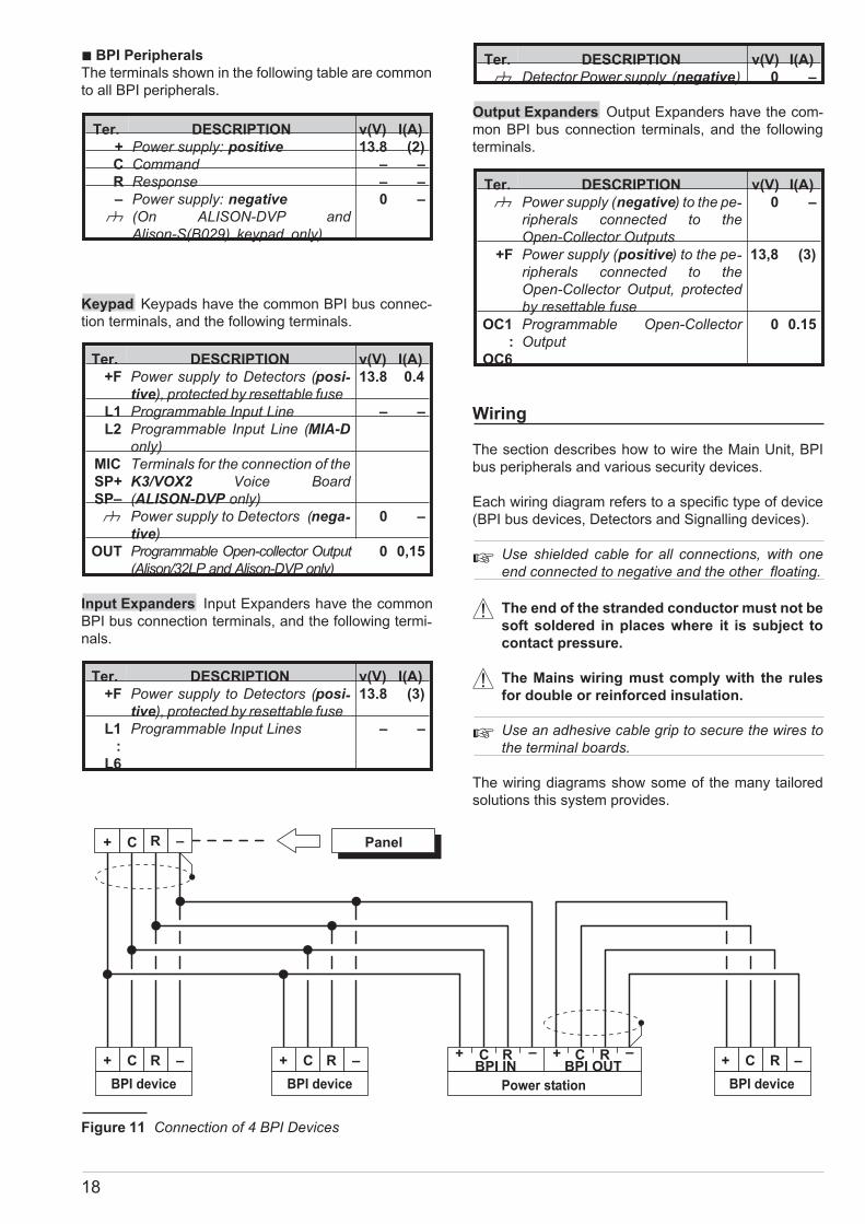
+ C R –
BPI device
C R+ –
BPI device
RC+ –
Panel
Power station
RC+RC+BPI IN BPI OUT
BPI device
RC+ –
Figure 11 Connection of 4 BPI Devices
About the Wiring Diagrams The locations of the ter-minals in the wiring diagrams may be different to those
on the board.
� the Zone terminals may belong to the Control panel,
Keypads or Output Expanders;
� the Open-Collector Output terminals may belong to
the Control panel or Output Expanders;
� the Input zone and the Open-Collector Output termi-nals (in the wiring diagrams) can be found on the
Main Unit or Expanders;
� only the terminals required for the connection are
shown in the wiring diagrams.
Connecting BPI Bus Devices
The BPI bus supports the following devices:
� up to 32 Keypads
� up to 32 Readers
� up to 32 Input Expanders
� up to 16 Output Expanders
� up to 8 Power stations
� up to 16 LED Keypads
Electrical Connections The BPI bus devices must be
connected in parallel to terminals [+], [C], [R], [–] on the
Main Unit, as shown in Fig. 11.
The Power Station has two groups of terminals for the
BPI bus connection: the BPI-IN group — for the Power
Station; and the BPI-OUT group — for the BPI devices
connected downstream of the Power Station.
The two groups of terminals are electrically isolated,
therefore, all the cables and devices connected down-stream of the Power Station will not load the Control
panel BPI bus.
Refer to the Power Station Instructions leaflet for further
details.
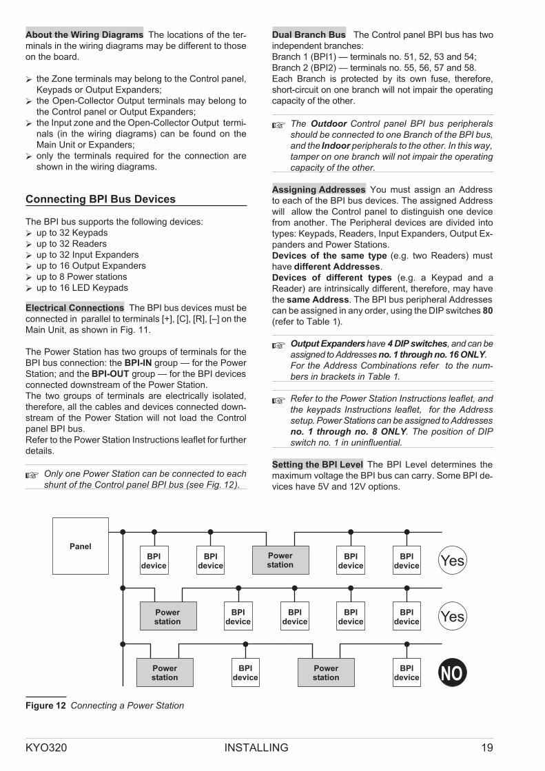
� Only one Power Station can be connected to eachshunt of the Control panel BPI bus (see Fig. 12).
Dual Branch Bus The Control panel BPI bus has two
independent branches:
Branch 1 (BPI1) — terminals no. 51, 52, 53 and 54;
Branch 2 (BPI2) — terminals no. 55, 56, 57 and 58.
Each Branch is protected by its own fuse, therefore,
short-circuit on one branch will not impair the operating
capacity of the other.
� The Outdoor Control panel BPI bus peripheralsshould be connected to one Branch of the BPI bus,and the Indoor peripherals to the other. In this way,tamper on one branch will not impair the operatingcapacity of the other.
Assigning Addresses You must assign an Address
to each of the BPI bus devices. The assigned Address
will allow the Control panel to distinguish one device
from another. The Peripheral devices are divided into
types: Keypads, Readers, Input Expanders, Output Ex-panders and Power Stations.
Devices of the same type (e.g. two Readers) must
have different Addresses.
Devices of different types (e.g. a Keypad and a
Reader) are intrinsically different, therefore, may have
the same Address. The BPI bus peripheral Addresses
can be assigned in any order, using the DIP switches 80
(refer to Table 1).
� Output Expandershave 4 DIP switches, and can beassigned to Addresses no. 1 through no. 16 ONLY.For the Address Combinations refer to the num-bers in brackets in Table 1.
� Refer to the Power Station Instructions leaflet, andthe keypads Instructions leaflet, for the Addresssetup. Power Stations can be assigned to Addressesno. 1 through no. 8 ONLY. The position of DIPswitch no. 1 in uninfluential.
Setting the BPI Level The BPI Level determines the
maximum voltage the BPI bus can carry. Some BPI de-vices have 5V and 12V options.
KYO320 INSTALLING 19
Yes
Yes
NO
BPIdevice
PanelPowerstation
BPIdevice
BPIdevice
BPIdevice
BPIdevice
Powerstation
BPIdevice
BPIdevice
BPIdevice
BPIdevice
Powerstation
BPIdevice
Powerstation
Figure 12 Connecting a Power Station

� This Control panel operates at 12V, therefore, allthe peripheral devices must be set at 12 V.
Using the Jumpers 69 and 73, set the BPI Level as fol-lows:
BPI Level Jumper 69 Jumper 73
5 V // 5 V 12 Vo// 5 V
12 V oo 5 V 12 V//o 5 V
� Refer to the Power station Instructions leaflet forthe BPI Level setup.
ALISON/32LP ASSIGNING ADDRESSES To assign
the addresses to the ALISON/32LP Keypad and Prox-
imity Reader work carefully through the following step:
1.Remove the frontplate in order to generate a Tamper
status.
2.Connect the Keypad to the Control panel BPI BUS
(terminals +, C, R, -).
3.Remove the jumper 73:
� after 5 seconds the keypad will emit an audible signal
and the 4 LEDs on the left (89a in Figure 8) will turn ON;
� the four pairs (up/down) of LEDs (89d in Figure 8) will
simulate 4 DIP switches;
� one of the first pair of LEDs will blink to indicate ac-cess to the Addressing phase.
4.Assign an Address to the Keypad.
� Use A or B to select the LED/DIP switch.
� Use C or D respectively, to turn the LED ON or
OFF as required, in accordance with the following
logic:
Upper RED LED ON = DIP switch ON
Lower LED ON = DIP switch OFF
� If you wish to cancel the setting and restart, press
e.
� NOTE: You can assign the same Address to the
Keypad and Proximity Reader as these devices
are intrinsically different.
5.PressE to confirm the selected Address:
� after several seconds the Keypad will emit an audi-ble signal, and the 4 LEDs on the right (see 89b in
Figure 8) will turn ON to indicate access to the Ad-
dressing phase of the built-in Proximity Reader.
� If you DO NOT wish to use the Proximity Reader,
press o. The ALISON/32LP will go back automati-
cally to the Keypad Addressing phase, at which
point, go to step 8. in this section.
� If you wish to use the Proximity Reader, go to step 6.
6.Following the instructions in step 4., assign an Ad-dress to the Reader.
� If you wish to cancel the setting and restart, press
e.
� NOTE: If you press e at this point, theALISON/32LP will cancel the setting and step backto the Keypad Addressing phase.
7. Once you have assigned the Keypad and Reader
Addresses, press E.
8. Reinsert the Jumper 73 immediately, in accordance
with the selected BPI Level (refer to “Setting up the BPI
Level”), then replace the frontplate.
ALISON-DVP ASSIGNING ADDRESSES On first
power up the Keypad will assume the preset Address
‘01’ (at default):
NOTE: If the buzzer volume is set at 0, the keypad will
be unable to emit audible signals (refer to ‘ADJUSTING
THE ON-BOARD BUZZER VOLUME’).
Work carefully through the following steps.
1. Generate Tamper status by removing the case.
2. Connect the Keypad to the Control panel BPI BUS.
3. Remove the Jumper 73 — after several seconds the
Keypad will emit an audible signal (long beep) to indi-
cate access to the programming phase.
4.Using keys Aor B, select the required operating mode:
If you intend using the Keypad with a Control panel:
— select “ALISON/DVP”, then press E to confirm.
On first power-up the display will show:
“ALISON/DVP”.
20
No. ADDRESS COMBINATIONS
1 2 3 4 5 6 7 8 9 10 11 12 13 14 15 16 17 18 19 20 21 22 23 24 25 26 27 28 29 30 31 32
1 (0) off off off off off off off off off off off off off off off off ONONONONONONONONONONONONONONONON
2 (1) off off off off off off off off ONONONONONONONONoff off off off off off off off ONONONONONONONON
3 (2) off off off off ONONONON off off off off ONONONONoff off off off ONONONON off off off off ONONONON
4 (3) off off ONONoff off ONON off off ONON off off ONONoff off ONON off off ONON off off ONONoff off ONON
5 (4) off ON off ONoff ONoff ON off ON off ON off ON off ONoff ONoff ON off ON off ON off ON off ONoff ONoff ON
Table 1 Expander Moduleand Power Station Addresses. The No. column shows the DIP switch number (1 through 5for devices with 5 DIP switches, and 1 through 4 in brackets for devices with 4 DIP switches).

5. The display will show “ALISON/DVP: 01”.
UsingC or D, select the Address for the Keypad.
6. Press E to confirm and continue or press e to
delete the setting — in both cases the Keypad will emit
an audible signal and go to step 7.
7. Using C or D, select an address for the Proximity
Reader, the display will show the current Address of the
Proximity Reader: “PROXI: 01” (preset at factory).
If you DO NOT INTEND using the Proximity Reader —
press o, the display will show the “PROXI: OFF”
message.
If you INTEND using the Proximity Reader — press
O, the display will show the “PROXI: 01” message.
8. PressE to confirm, or presse to delete the setting
— in both cases the Keypad will emit an audible signal and
the display will show the “CALL SERVICE” message.
Re-insert the jumper 73 and replace the case, the Keypad
will exit the programming session automatically.
� A long beep on first power up indicates that theALISON/DVP keypad memory is devoid of an ESN andtherefore,cannotbeenrolledbyKYO320ControlPanels.
ALISON-S(B029) ASSIGNING ADDRESSES On
first power up the Keypad will assume the preset Ad-dress ‘01’ (at default).
� You can exit the Programming phase at any pointin the following procedure by inserting the jumper73 or by closing the Tamper switch.
NOTE: If the buzzer volume is set at 0, the keypad will
not emit any audible signals (refer to ‘ADJUSTING THE
ON-BOARD BUZZER VOLUME’).
1. Generate Tamper status by removing the frontplate.
2. Connect the Keypad to the Control panel BPI BUS.
3. Remove the Jumper 73 — after several seconds the
Keypad will emit an audible signal (long beep) to indi-
cate access to the programming phase and the display
will show “ALISON/S: 01”.
4. UsingC or D, select the Address for the Keypad.
5.Press E to confirm, or press e to delete the set-ting — in both cases the Keypad will emit an audible sig-nal, and the display will show the “CALL SERVICE”
message. Re-insert the jumper 73 and replace the
frontplate, the Keypad will exit the programming ses-sion automatically.
� BPI bus Wiring Limitations
Due to Voltage drops and stray capacitance caused by
the Control panel BPI bus connections, the following
wiring limitations must be respected:
� the maximum wire length between the Control
panel and the BPI peripheral must not exceed 500
metres;
� the overall wire length of each branch of the Control
panel BPI bus must not exceed 1000 metres.
In order to allow the BPI peripherals to operate properly,
11.5V or more must be present across terminals [+] and
[–]. If a lower voltage is present, it can be boosted by:
� increasing the wire section that supplies the Control panel
BPI device (the wires that connect [+] and [–] of the Control
panel to terminals [+] and [–] of the BPI device);
� connecting some of the BPI peripherals downstream
of a Power Station (these devices will be powered by
the Power Station, therefore, will not load the Control
panel BPI bus);
� using a Power Station to provide the voltage for the
BPI peripheral load.
� The cable length downstream of a Power stationshould not to be included the overall wire length foreach branch of the Control panel BPI bus.
Due to Voltage drops and stray capacitance caused by
the Power Station BPI bus connections, the following
wiring limitations must be respected:
� the maximum wire length between the Power Sta-tion (BPIOUT terminals) and the BPI peripheral
must not exceed 500 metres;
� the overall wire length between the Power Station
(BPIOUT terminals) and the BPI bus peripherals
must not exceed 1000 metres.
KYO320 INSTALLING 21
BALANCE TYPES
R NO NC 10 K 10 K ALARM DOUBLE GLASS BREAK
� STANDBY ALARM ALARM ALARM TAMPER TAMPER
10 K ALARM STANDBY STANDBY STANDBY ALARM STANDBY
5 K ALARM STANDBY SHORTED ALARM STANDBY ALARM
0 ALARM STANDBY SHORTED ALARM SHORTED SHORTED
Table 2 Balance Types: the R column shows the resistance across the Zone terminal and the Negative during thecorresponding status (� indicates that the terminal is open; 0 indicates that the terminal is shorted to negative)

Connecting Detectors
The KYO320 system has 8 zones, expandable to 3441
zones by means of M-IN/6, MIA-D, ALISON-DVP
and/or Alison/32LP Keypads and the VectorRX:
8 Zones on the Main Unit64 Zones
16 Zones
on 32MIA-DKeypads (2 Zones per Keypad)on 16 Alison/32LP Keypads
192 Zones on 32 Input Expanders (6 Zones per Ex-pander)
64 Zones
344 Zones
on the Wireless ReceiversTotal
The Receiver zones (wireless zones) are for the wireless
detectors. The Main Unit, Keypad and Input Expander
zones (hardwired zones) are for the hardwired detectors.
This section describes the connection of hardwired de-tectors.
The terminals of the hardwired zones are marked [L1],
[L2], etc.
The following terminals can be used for the power sup-ply to the detectors:
either [+F] and [M] (negative) or [+F1] and [M] (nega-tive), for each zone on the Main Unit.
13.8 V positive is present on Main Unit [+F] and [+F1] ter-minals — protected by fuses 37 and 36 (F 1.85A).
[+F] and [M] (negative) for each pair of zones on
Keypads and Input Expanders.
13.8 V positive is present on Keypad and Input Expander
[+F] terminals — protected by resettable fuse (0.4 A).
Each zone can support several detectors. However, if
more than one detector is connected, the Control panel
will be unable to identify the detector in the event of an
Alarm.
This system can detect Alarm, Tamper and Short-circuit
on hardwired zones:
22
detector
N. C. A.
L1+F
S.
Panel
tamper line
Input exp. Keypad
Figure 13 Connecting a Detector to a zone with Normally Closed balance
detector
N. C. A.
L1+F
S.
tamper line
Panel Input exp. Keypad
Figure 14 Connecting a Detector to a zone with 10 K or 10 K Alarm only balance
1 If you install MIA-D Keypads (2 on-board zones), the system can be expanded to 312 zones. If you installALISON-DVP Keypads (1 on-board zone), the system can be expanded to 280 zones and 16 LED Keypads(1 zone per Keypad).

� Zone Alarm will be signalled by an Alarm on zone
no. event;
� Zone Tamper will be signalled by a Tamper on zone
no. event;
� Short-circuit will be signalled by a Tamper on zone
no. event.
The Zone status depends on several parameters (refer
to “Hardwired Zones” in the “PROGRAMMING FROM
PC” section). This section refers to the Balance type. If
only this parameter is considered, the zone status will
depend on the resistance between its terminal and neg-ative, as shown in Table 2.
The following paragraphs describe the connections of
various types of detectors.
� The 10 K� resistors are included in the Resistor pack.
The 10 K� resistors have brown, black, orange and
gold bands. The last band (gold) indicates the toler-ance, and therefore, may be a different colour.
� Connecting Motion Detectors
Most Motion detectors have Normally-Closed Contacts
(NC in the wiring diagram), and Normally-Closed Tam-per Contacts (AS in the wiring diagram).
The zone balance can be programmed as:
– Normally Closed
– Normally Open
– 10 K
– 10 K Alarm
– Double
– Glass Break
The connection type depends on the selected balance.
In Figures 13, 14 and 15 the:
� [+] and [–] terminals represent the positive and nega-tive terminals;
� [NC] terminals are the Normally Closed Alarm Con-tacts of the detector;
� [AS] terminals are the Normally Closed Tamper Con-tacts of the detector.
Normally Closed The wiring diagram in Fig. 13 illus-trates the connection of a detector to a zone with
Normally Closed balance.
Normally Closed balance will allow the Control panel to
detect Alarm status on the zone:
– the zone will hold Standby status whilst connected to
negative;
– the zone will trigger Alarm under all other conditions.
To provide Tamper detection: connect the Tamper con-
KYO320 INSTALLING 23
detector
N. C. A.
L1+F
S.
Panel Input exp. Keypad
Figure 15 Connecting a Detector to a zone with Double balance
L1+F
glassbreak
detector
glassbreak
detector
glassbreak
detector
Panel Input exp. Keypad
Figure 16 Connecting 3 Glass Break Detectors to a zone with Glass Break balance

tact of the detector to the Control panel Tamper Line, or to a
24h zone (refer to “Connecting Tamper Contacts”).
10 K The wiring diagram in Fig. 14 illustrates the con-nection of a detector to a zone with 10 K, or 10 K Alarm
Only balance.
! The 10 K� resistor must be connected to the
last detector of the zone.
10 K balance will allow the Control panel to detect
Alarm and Short-circuit on the zone:
– the zone will hold Standby status when connected to
negative via a10 K� resistor;
– the zone will trigger short-circuit when connected to
negative;
– the zone will trigger Alarm under all other conditions.
To provide Tamper detection: connect the Tamper con-tact of the detector to the Control panel Tamper Line, or
to a 24h zone (refer to “Connecting Tamper Contacts”).
10 K Alarm Only The wiring diagram in Fig. 14 illus-trates the connection of a detector to a zone with 10 K,
or 10 K Alarm Only balance.
! The 10 K� resistor must be connected to the
last detector of the zone.
10 K Alarm Only balance will allow the Control panel to
detect Alarm status on the zone:
– the zone will hold Standby status when connected to
negative via a10 K�;
– the zone will trigger Alarm under all other conditions.
Double The wiring diagram in Fig. 15 illustrates the
connection of a detector to a zone with Double balance.
This type of zone will allow the Control panel to detect
zone Alarm, Tamper and Short-circuit:
– the zone will hold Standby status whilst connected to
negative via a 5 K� resistor (i.e. using two 10 K� resis-tors connected in parallel);
– the zone will trigger short-circuit when connected to
negative;
– the zone will trigger Tamper when open;
– the zone will trigger Alarm under all other conditions.
� Zones with Double balance can detect and signalAlarm and Tamper by means of just two wires.
To provide Tamper detection on zones with NormallyClosed or 10 K balance:either connect the detector tamper contact to the Con-trol panel Tamper Line — this type of connection does
not provide identification of the tampered detector;
or connect the detector tamper contact to a 24h zone —
this type of connection requires two zones — one for
Alarm detection, and the other for Tamper detection (re-fer to “Connecting Tamper Contacts”).
� Glass Break Detectors
Fig. 16 illustrates the connection of 3 Glass Break de-tectors to a zone with Glass Break balance.
! Glass Break zones accept up to 20 detectors.
The continuous lines in the wiring diagram represent
the soft-soldered conductors of the detector, and the
broken lines represent the copper wires.
Connect the Glass Break detectors in parallel between
the zone and negative, and a 10 kW resistor in parallel
to the last detector.
This balance type will allow the Control panel to detect
Alarm, Tamper and Short-circuit on the zone:
– the zone will hold Standby status whilst connected to
negative via a 10 KW resistor;
– the zone will trigger short-circuit when connected to
negative;
– the zone will trigger Tamper when open;
– the zone will trigger Alarm under all other conditions.
� Connecting Roller-Blind and Vibration Detectors
Zones 1 through 8 of KYO320 support Roller-blind and
Vibration detectors. The zones must be programmed
respectively with either the Vibration or Roller-blind at-tribute (refer to the ‘PROGRAMMING’, Hardwired
zones, in this Manual), and can be set up as Normally
Closed (N.C.) or Balanced 1K ohm (BAL) or Custom-
ized (for NC or NO Balanced zones only, and in this
case the Threshold Voltage must be in Standby status).
24
firedetector
firedetector
firedetector
+A +A+AR RR+B
+F
OC1
L2
+B+B– – –
+F L3 +F L4 Panel Input exp.
Panel Output exp.
Keypad
Figure 17 Connecting 3 Fire Detectors to a Zone with Normally Open balance
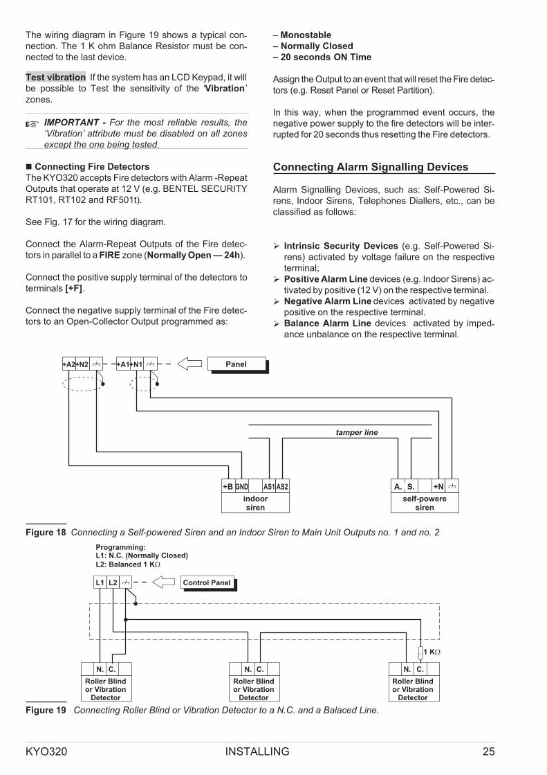
The wiring diagram in Figure 19 shows a typical con-nection. The 1 K ohm Balance Resistor must be con-nected to the last device.
Test vibration If the system has an LCD Keypad, it will
be possible to Test the sensitivity of the ‘Vibration’
zones.
� IMPORTANT - For the most reliable results, the‘Vibration’ attribute must be disabled on all zonesexcept the one being tested.
� Connecting Fire Detectors
The KYO320 accepts Fire detectors with Alarm -Repeat
Outputs that operate at 12 V (e.g. BENTEL SECURITY
RT101, RT102 and RF501t).
See Fig. 17 for the wiring diagram.
Connect the Alarm-Repeat Outputs of the Fire detec-tors in parallel to a FIRE zone (Normally Open — 24h).
Connect the positive supply terminal of the detectors to
terminals [+F].
Connect the negative supply terminal of the Fire detec-tors to an Open-Collector Output programmed as:
– Monostable
– Normally Closed
– 20 seconds ON Time
Assign the Output to an event that will reset the Fire detec-tors (e.g. Reset Panel or Reset Partition).
In this way, when the programmed event occurs, the
negative power supply to the fire detectors will be inter-rupted for 20 seconds thus resetting the Fire detectors.
Connecting Alarm Signalling Devices
Alarm Signalling Devices, such as: Self-Powered Si-rens, Indoor Sirens, Telephones Diallers, etc., can be
classified as follows:
� Intrinsic Security Devices (e.g. Self-Powered Si-
rens) activated by voltage failure on the respective
terminal;
� Positive Alarm Line devices (e.g. Indoor Sirens) ac-tivated by positive (12 V) on the respective terminal.
� Negative Alarm Line devices activated by negative
positive on the respective terminal.
� Balance Alarm Line devices activated by imped-ance unbalance on the respective terminal.
KYO320 INSTALLING 25
+A2+N2
self-poweresiren
Panel
A. S.AS1 AS2GND+B
+A1+N1
indoorsiren
tamper line
+N
Figure 18 Connecting a Self-powered Siren and an Indoor Siren to Main Unit Outputs no. 1 and no. 2
Roller Blindor Vibration
Detector
N.
L1
C.
L2 Control Panel
N. C. N. C.
Roller Blindor Vibration
Detector
Roller Blindor Vibration
Detector
Figure 19 Connecting Roller Blind or Vibration Detector to a N.C. and a Balaced Line.

This Control panel has 6 Outputs — expandable to 118
by means M-OUT/6 Outputs Expanders:
6 Outputs on the Main Unit96 Outputs
16 Outputs
118Outputs
on 16 Output Expanders (6 Outputs perExpander)On 16 LED Keypads (1 Output per Key-pad)Total
The three Outputs on the Main Unit (no. 1, 2, and 3)
comprise terminals:
� +N1, +A1, C1-NC1-NA1
� +N2, +A2, C2-NC2-NA2
� +N3, +A3, C3-NC3-NA3
All other Outputs comprise terminals OC1, OC2, etc.
The Standby status of the Outputs can be programmed
as follows:
� [+N] terminals can be connected to positive (13.8 V)
or can be open, and therefore can be used to activate
Intrinsic Security Devices;
� [+A] terminals can be open or connected to positive
(13.8 V), and therefore can be used to activate Posi-tive Alarm Line devices;
� [C] terminals can be connected to their respective
terminals [NC] or [NA], and therefore, can be used to
activate all types of signalling devices;
� [OC] terminals can be open or connected to nega-tive, and therefore, can be used to activate Negative
Alarm Line devices
� The OC terminals on the Main Unit can switch amaximum of 1 A whereas, the OC terminals on theOutput Expanders can switch a maximum of0.15 A. An Omnia/4R Relay board is required toswitch higher values.
The activation/restoral of Outputs depends on various
parameters (refer to “Outputs” under “PROGRAMMING
FROM PC”).
The wiring diagram in Fig. 18 illustrates connection of a
Self-powered Siren and an Indoor Siren to Outputs
no. 1 and no. 2 on the Main Unit:
� Outputs no. 1 and no. 2 on the Main Unit are pro-grammed as Normally Closed;
� [+N] is the positive power and Input of the Self-pow-
ered Siren. The Siren will activate when positive
(13.8 V) fails on the [+N] terminal;
� [+B] is the positive power and Input of the Indoor Si-ren. The Siren will activate when positive (13.8 V) is
applied to the [+N] terminal;
� [M] and [GND] are the negative power terminals of
the Self-powered Siren and Indoor Siren;
� [A.S.] and [AS1-AS2] are the Normally Closed Tam-per contacts of the Self-powered Siren and Indoor Si-ren.
To provide Tamper detection: connect the Signalling
device Tamper contact to the Control panel Tamper
Line or to a 24h zone (refer to “Connecting Tamper
Contacts”).
� Supervised Outputs
Outputs no. 1, 2 and 3 can be set up as Supervised Out-puts. This type of output must be programmed as Nor-mally Closed (refer to “Attributes” under “Outputs” in the
“PROGRAMMING” section). The Control panel can de-tect short-circuit and Connection interrupt to terminals
+A of Outputs with this attribute. The wiring diagram in
Fig. 20 illustrates the connection of an Indoor Siren to a
Supervised Output using a 2.2 K� across terminals +A
and negative. Sieze Tamper Microswitch
The two 2.2 K� resistors (included in the package)
have 3 red bands and a gold band. The last band (gold)
indicates the tolerance, therefore, it may be a different
colour.
� The 2.2 K� resistor must be connected to the lastdevice on the Output, otherwise it will have no ef-fect.
Short-circuit and connection interruption to terminal +A
of Supervised Outputs, will be signalled by:
� Tamper on supervised output — relative to the
Output;
� flashing on the a indicator on the Keypads.
26
+A3+N3 Panel
AS1 AS2GND+B
indoorsiren
tamper line
Figure 20 Connecting an Indoor Siren to a Controlled Output on the Main Unit
� Thea indicator will flash until the cause of Alarmis cleared (memory). The a indicator will stopflashing when the Control panel resets.
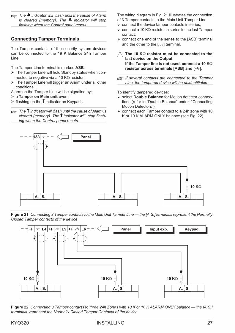
Connecting Tamper Terminals
The Tamper contacts of the security system devices
can be connected to the 19 K Balance 24h Tamper
Line.
The Tamper Line terminal is marked ASB:
� The Tamper Line will hold Standby status when con-
nected to negative via a 10 K� resistor;
� The Tamper Line will trigger an Alarm under all other
conditions.
Alarm on the Tamper Line will be signalled by:
� a Tamper on Main unit event;
� flashing on the T indicator on Keypads.
� The T indicator will flash until the cause of Alarm iscleared (memory). The T indicator will stop flash-ing when the Control panel resets.
The wiring diagram in Fig. 21 illustrates the connection
of 3 Tamper contacts to the Main Unit Tamper Line:
� connect the device tamper contacts in series;
� connect a 10 K� resistor in series to the last Tamper
contact;
� connect one end of the series to the [ASB] terminal
and the other to the [M] terminal.
! The 10 K� resistor must be connected to the
last device on the Output.
If the Tamper line is not used, connect a 10 K�
resistor across terminals [ASB] and [M].
� If several contacts are connected to the TamperLine, the tampered device will be unidentifiable.
To identify tampered devices:
� select Double Balance for Motion detector connec-tions (refer to “Double Balance” under “Connecting
Motion Detectors”);
� connect each Tamper contact to a 24h zone with 10
K or 10 K ALARM ONLY balance (see Fig. 22).
KYO320 INSTALLING 27
A. A.A.S.
ASB
S.S.
Panel
Figure 21 Connecting 3 Tamper contacts to the Main Unit Tamper Line — the [A.S.] terminals represent the NormallyClosed Tamper contacts of the device
A. S.
L4+F Panel Input exp.L5+F L6+F
A. S. A. S.
Keypad
Figure 22 Connecting 3 Tamper contacts to three 24h Zones with 10 K or 10 K ALARM ONLY balance — the [A.S.]terminals represent the Normally Closed Tamper Contacts of the device

� Tamper contact zones can be programmed withNormally Closed balance, in which case, the 10 K�
resistors must not be connected.
Connecting the Telephone Line
In order to allow use of the Dialler, Digital communicator
and Teleservice facilities, the telephone line must be
connected to terminals [LE], as shown in Fig. 23.
This Control panel can detect Telephone line trouble
(Line down), which will be signalled when the voltage on
the [LE] terminals drops below 3 V for over 45 seconds.
Telephone line trouble will be signalled by:
� the Line-down event;
� ON status of theG indicator on Keypads;
� flashing on the i indicator on Keypads.
The Control panel will signal restoral when the voltage
on the LE] terminals returns to 3 V for over 15 seconds.
� If the telephone line IS NOT CONNECTED to thePanel, the Telephone line check option must beDISABLED. If it is not Disabled, the Control panelwill signal Line-down status persistently (refer to“Telephone” in the “PROGRAMMING” section).
Connect Line-sharing devices (Fax, Answerphone,
etc.) to the [LI] terminals. This will allow the Control
panel to take priority ONLY in the event of an alarm.
Connect the [-] terminal to the Mains Earth — this will
protect the PCB against surges from the Telephone line.
! Ensure that the Mains Earth is fully intact and
operating properly before connecting the Tele-
phone line.
Connecting a Power Supply
In order to comply with the Safety regulations in force,
the Mains must be equipped with a bipolar isolating de-
vice for protection against over voltage and short-circuit
to Earth (e.g. automatic isolating switch).
The KYO320 is powered from the Mains (230V/50 Hz)
through a Switching power supply, located inside the
cabinet. The cabinet can also house a backup battery
(not included) for power backup during Mains failure.
Programmed data will be protected at all times by the
RAM battery.
Mains failure will be signalled by the:
� OFF status of indicator 28 on the Main board;
� ON status of theG indicator on Keypads;
� Warning Mains failure event.
� The Warning Mains failure event will be signalledafter the programmed delay (refer to “Filter Times”in the “PROGRAMMING FROM PC” section).
The Control panel will monitor the battery at all times,
(refer to Static Test and Dynamic Test).
Static Test The Static Test monitors the battery
charge during Mains failure. Low battery status (below
11.4 V) will be signalled by the:
� Low battery event;
� ON status of theG indicator on Keypads.
If this occurs, the Mains power must be restored before
the battery empties, otherwise, the system will shut-down.
Low battery restoral (over 12.3 V) will be signalled by:
� the end of the Warning low battery event;
� OFF status of theG indicator on Keypad.
� The control panel shuthdown the backup Batterydue to voltage drop (Safety threshold 9,6V), be-cause this condition can damage the battery
Dynamic Test The Dynamic Test monitors the oper-ating capacity of the battery. Failed Test (battery does
not meet the Test requirements) will be signalled by the:
� Warning power trouble event;
� ON status of theG indicator on Keypads.
If this occurs, the backup battery must be replaced im-mediately, otherwise, the system will be unable to func-tion in the event of Mains failure (black-out).
28
telephoneplug
a
LE LI Mainsearth
Th
isco
nn
ecti
on
isn
ec
es
sa
ry!
Panel
b
c
Figure 23 Connecting the Telephone Line to the Main Unit
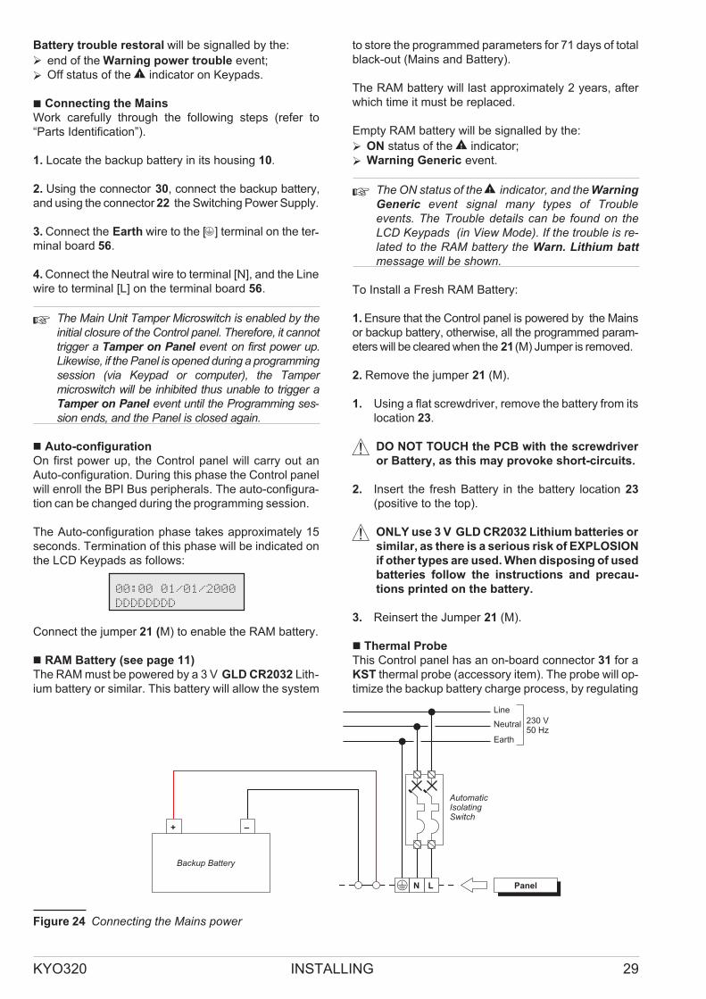
Battery trouble restoral will be signalled by the:
� end of the Warning power trouble event;
� Off status of theG indicator on Keypads.
� Connecting the Mains
Work carefully through the following steps (refer to
“Parts Identification”).
1. Locate the backup battery in its housing 10.
2. Using the connector 30, connect the backup battery,
and using the connector 22 the Switching Power Supply.
3. Connect the Earth wire to the [Q] terminal on the ter-minal board 56.
4. Connect the Neutral wire to terminal [N], and the Line
wire to terminal [L] on the terminal board 56.
� The Main Unit Tamper Microswitch is enabled by theinitial closure of the Control panel. Therefore, it cannottrigger a Tamper on Panel event on first power up.Likewise, if the Panel is opened during a programmingsession (via Keypad or computer), the Tampermicroswitch will be inhibited thus unable to trigger aTamper on Panel event until the Programming ses-sion ends, and the Panel is closed again.
� Auto-configuration
On first power up, the Control panel will carry out an
Auto-configuration. During this phase the Control panel
will enroll the BPI Bus peripherals. The auto-configura-
tion can be changed during the programming session.
The Auto-configuration phase takes approximately 15
seconds. Termination of this phase will be indicated on
the LCD Keypads as follows:
00:00 01/01/2000
DDDDDDDD
Connect the jumper 21 (M) to enable the RAM battery.
� RAM Battery (see page 11)
The RAM must be powered by a 3 V GLD CR2032 Lith-
ium battery or similar. This battery will allow the system
to store the programmed parameters for 71 days of total
black-out (Mains and Battery).
The RAM battery will last approximately 2 years, after
which time it must be replaced.
Empty RAM battery will be signalled by the:
� ON status of theG indicator;
� Warning Generic event.
� The ON status of theG indicator, and the Warning
Generic event signal many types of Troubleevents. The Trouble details can be found on theLCD Keypads (in View Mode). If the trouble is re-lated to the RAM battery the Warn. Lithium batt
message will be shown.
To Install a Fresh RAM Battery:
1. Ensure that the Control panel is powered by the Mains
or backup battery, otherwise, all the programmed param-
eters will be cleared when the 21(M) Jumper is removed.
2. Remove the jumper 21 (M).
1. Using a flat screwdriver, remove the battery from its
location 23.
! DO NOT TOUCH the PCB with the screwdriver
or Battery, as this may provoke short-circuits.
2. Insert the fresh Battery in the battery location 23
(positive to the top).
! ONLY use 3 V GLD CR2032 Lithium batteries or
similar, as there is a serious risk of EXPLOSION
if other types are used. When disposing of used
batteries follow the instructions and precau-
tions printed on the battery.
3. Reinsert the Jumper 21 (M).
� Thermal Probe
This Control panel has an on-board connector 31 for a
KST thermal probe (accessory item). The probe will op-
timize the backup battery charge process, by regulating
KYO320 INSTALLING 29
L PanelN
AutomaticIsolatingSwitch
+ –
Backup Battery
Line
Neutral
Earth
230 V50 Hz
Figure 24 Connecting the Mains power

the charge voltage in accordance with the temperature
of the backup battery.
Work carefully through the following instructions (refer
to the figure on page 10):
1. Connect the probe 9 to the connector 62 (PTC) on
the Switching Power supply.
2. Attach the probe to the backup battery, in such a
way as to obtain optimum heat transfer.
3. Connect the connector of backup battery 53 on
the PCB.
4. Measure the Probe temperature.
5. Using the graph in Figure 25 and/or Table 3, find
the value (in accordance with the battery tempera-ture) that the Switching Power supply output volt-age will be based on.
6. Using the trimmer 54 , adjust the voltage on the ter-minal board 55 to the required value.
30
-10 -5 0 5 10 15 20 25 30 35 40 45 50
13,0
13,5
14,0
14,5
VO
LTA
GE
(V)
TEMPERATURE (°C)
a)
13,7
22
Figure 25 Switching Power Supply Output Voltage graph. To find the Output Voltage using the graph: — indicate theProbe temperature on the TEMPERATURE (°C) axis; draw a line from the temperature value point up to the curve a);draw a line from the intersection point across to the VOLTAGE (V) axis; adjust the Output Voltage of the SwitchingPower Supply to the resultant value. For example, if the Probe temperature is 22 °C, the Output Voltage of theSwitching Power Supply must be set at 13.7 V.
TEMPERATURE (°C) -10 -5 0 5 10 15 20 25 30 35 40 45 50
VOLTAGE (V) 14.5 14.4 14.3 14.1 14.0 13.9 13.7 13.6 13.5 13.4 13.3 13.2 13.1
Table 3 Switching Power Supply Output Voltage chart. To find the Output Voltage using the chart: — select the near-est value to the Probe temperature on the TEMPERATURE (°C) row; read the corresponding value on the VOLTAGE
(V) row; adjust the Output Voltage of the Switching Power Supply to the indicated value. For example, if the Probe tem-perature is 22 °C, the Output Voltage of the Switching Power Supply must be set at 13.7 V.

PROGRAMMING
You can program the system using a LCD Keypad, or
using the KYO320 downloading software from the
Bentel Security Suite Software package (accessory
item).
� The following options and parameters CANNOTBE programmed from Keypads:— the Sensitivity of the Hardwired Zones;the Scheduler parameters — except for the Max.
no. overtime requests and Overtime Request;— the Timers.— Enable Keypad Codes (LCD and LED keypads)and/or Keys /Cards.The following operations CAN BE DONE fromKeypads ONLY:— Record and playback of Voice Messages;— Enable and Program Key/Card Codes;— Request Log Printout;— Enrol/Unenrol the B-NET module.
If you are programming the system from a Keypad, refer
to the instructions in the “PROGRAMMING FROM
KEYPAD” manual.
� This section provides information on the systemparameters, and should be referred to also whenprogramming from a Keypad.
Read this section thoroughly to learn how to install and
use the KYO320 software application.
1. Install the KYO320 software application as de-scribed in the Security Suite manual.
2. Run the KYO320 application.
3. Select the Control panel Type (refer to the Cus-tomer data paragraph) and the Firmware Release
(refer to the Options paragraph in the Security
Suite manual).
4. NOTE: When programming the KYO320, select
File > INIT then setup the Panel Type and Firm-ware Release in the Parameters window.
5. Program the parameters (refer to the respective
paragraphs for instructions).
6. Download the programmed parameters (refer to the
respective paragraph: On-site Programming via
Computer or Remote Programming via Computer).
� The programmed parameters can be saved onhard or floppy disk, and downloaded to the Controlpanel via modem or on-site. The programmed pa-rameters can be renamed and reused for differentCustomers (refer to “Save” and “Open Customer”
in the “Bentel Security Suite” Manual).
The system parameters are organized in Pages. The
Programming Pages in this section are congruent with
the KYO320 software structure.
Configuration (Enrolling Devices)
On startup the Control panel will automatically enrol all
the BPI Bus peripherals (refer to “Power supply connec-
tion” under “INSTALLATION”). Any changes after auto-
matic enrollment must be made by the Installer.
During the polling process, the Control panel will match the
interrogation result with the stored configuration and, in the
event of mismatch, will generate the respective warning.
� If the Control Panel is connected to a computer, itwill be possible to view the configuration by loadingthe Configuration page.
The Configuration section is divided into pages — one
for each type of device (Keypads, Input Expanders,
Output Expanders, Readers, Power Supply Stations
and Accessories).
The following programming instructions refer to param-eters common to all BPI devices. For instructions on
how to program the parameters of a specific device, re-fer to the relevant paragraph.
� The devices connected to the BPI Bus must be Se-lected, otherwise the system will be unable to enrol them.
� The Select button (on the bottom of the page) willallow you to select/deselect all the devices on thepage at once.
The Control panel cannot manage unenrolled peripherals.
If a peripheral device has not been connected properly
to the BPI bus, or fails to respond (Device Lost) due to
Trouble or Tamper, an X will be shown above thes icon
on the Keypad, and the Control Panel will generate the
respective event, as follows:
� Warning Readers = Lost Device
KYO320 PROGRAMMING 31
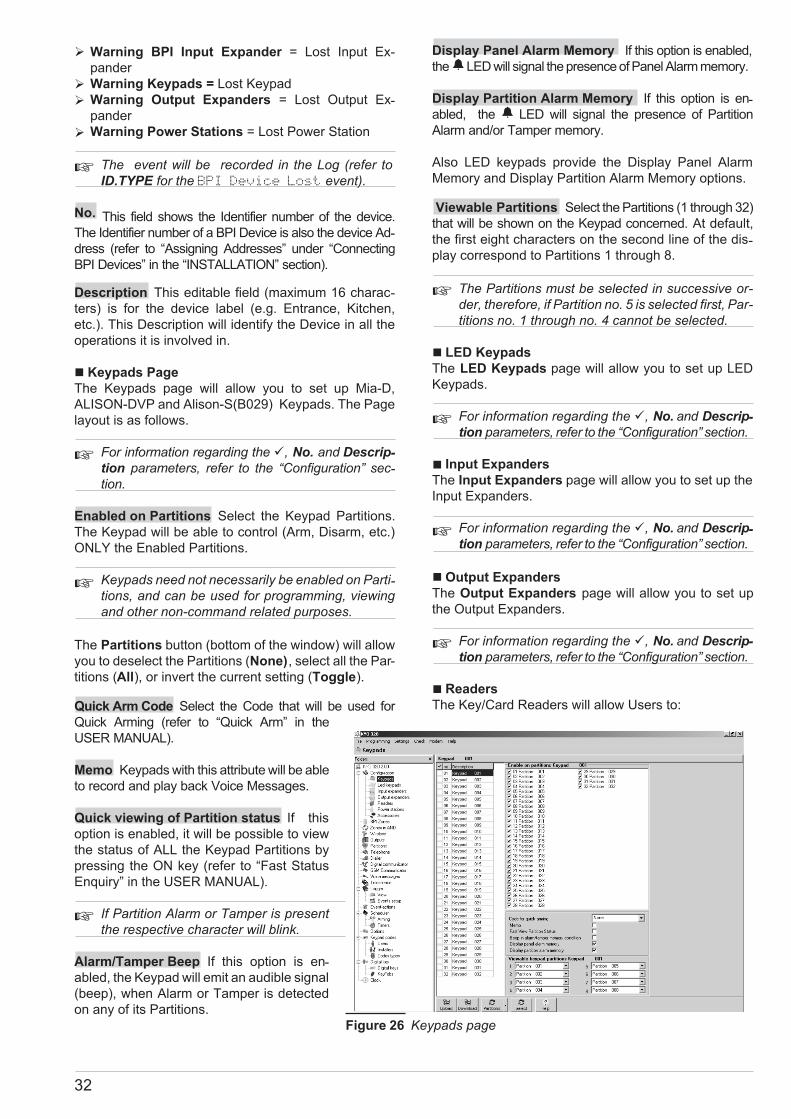
� Warning BPI Input Expander = Lost Input Ex-
pander
� Warning Keypads = Lost Keypad
� Warning Output Expanders = Lost Output Ex-pander
� Warning Power Stations = Lost Power Station
� The event will be recorded in the Log (refer toID.TYPE for the BPI Device Lost event).
No. This field shows the Identifier number of the device.
The Identifier number of a BPI Device is also the device Ad-dress (refer to “Assigning Addresses” under “Connecting
BPI Devices” in the “INSTALLATION” section).
Description This editable field (maximum 16 charac-
ters) is for the device label (e.g. Entrance, Kitchen,
etc.). This Description will identify the Device in all the
operations it is involved in.
� Keypads Page
The Keypads page will allow you to set up Mia-D,
ALISON-DVP and Alison-S(B029) Keypads. The Page
layout is as follows.
� For information regarding the �, No. and Descrip-tion parameters, refer to the “Configuration” sec-tion.
Enabled on Partitions Select the Keypad Partitions.
The Keypad will be able to control (Arm, Disarm, etc.)
ONLY the Enabled Partitions.
� Keypads need not necessarily be enabled on Parti-tions, and can be used for programming, viewingand other non-command related purposes.
The Partitions button (bottom of the window) will allow
you to deselect the Partitions (None), select all the Par-
titions (All), or invert the current setting (Toggle).
Quick Arm Code Select the Code that will be used for
Quick Arming (refer to “Quick Arm” in the
USER MANUAL).
Memo Keypads with this attribute will be able
to record and play back Voice Messages.
Quick viewing of Partition status If this
option is enabled, it will be possible to view
the status of ALL the Keypad Partitions by
pressing the ON key (refer to “Fast Status
Enquiry” in the USER MANUAL).
� If Partition Alarm or Tamper is presentthe respective character will blink.
Alarm/Tamper Beep If this option is en-abled, the Keypad will emit an audible signal
(beep), when Alarm or Tamper is detected
on any of its Partitions.
Display Panel Alarm Memory If this option is enabled,
theaLED will signal the presence of Panel Alarm memory.
Display Partition Alarm Memory If this option is en-abled, the a LED will signal the presence of Partition
Alarm and/or Tamper memory.
Also LED keypads provide the Display Panel Alarm
Memory and Display Partition Alarm Memory options.
Viewable Partitions Select the Partitions (1 through 32)
that will be shown on the Keypad concerned. At default,
the first eight characters on the second line of the dis-play correspond to Partitions 1 through 8.
� The Partitions must be selected in successive or-der, therefore, if Partition no. 5 is selected first, Par-titions no. 1 through no. 4 cannot be selected.
� LED Keypads
The LED Keypads page will allow you to set up LED
Keypads.
� For information regarding the �, No. and Descrip-tion parameters, refer to the “Configuration” section.
� Input Expanders
The Input Expanders page will allow you to set up the
Input Expanders.
� For information regarding the �, No. and Descrip-tion parameters, refer to the “Configuration” section.
� Output Expanders
The Output Expanders page will allow you to set up
the Output Expanders.
� For information regarding the �, No. and Descrip-
tion parameters, refer to the “Configuration” section.
� Readers
The Key/Card Readers will allow Users to:
32
Figure 26 Keypads page

� Arm Partitions
� Disarm Partitions
� Arm in A and B Mode
� Stop Partition Alarms
� Commands will affect ONLY the Partitions com-mon to both the Reader and Key/Card in use.
For example, if you attempt to Arm the system at a Reader
that is enabled on Partitions no. 1 and no. 2, with a
Key/Card that is enabled on Partitions no. 1 and no. 3,
ONLY Partition no. 1 will Arm (Partition no. 1 is common to
both the Reader and Key/Card). The Readers page will al-low you to set up the Readers, as follows.
� For information regarding the �, No. and Descrip-tionparameters, refer to the “Configuration” section.
M This attribute will enable the Reader for Monitoring
purposes (i.e. To signal specific events — to be pro-grammed by the Installer).
� Monitoring Readers (Readers with the M attrib-ute) CANNOT be used for system control purposesbut will be able to generate Valid Key, Key at
Reader events and Valid Key on Partition.
The Expand button at the bottom of the page will open
the Readers table.
If you are programming System Control Readers: select
the Reader Partitions, and set up the A and B Mode
Arming configurations (refer to the following paragraphs).
If you are programming Monitoring Readers: select the
Events to be monitored (refer to the following paragraphs).
RED spot This row will allow you to assign (�) the
Reader to the Partitions (01 through 32).
To view the Partition Description: click the Descrip-
tion button (bottom of page) then position the cursor on
the Partition check box.
To highlight a Reader: hold down the SHIFT key and
click anywhere on the Reader table, then release the
SHIFT key.
To highlight a group of Readers: hold down the SHIFT
key and click anywhere on the tables of the first and last
Readers of the group, then release the SHIFT key.
To assign the Reader Partitions (quick mode): highlight
the Reader concerned, click the Partitions button then
select:
None — to Disable the highlighted Readers on all Par-
titions;
All — to Enable the highlighted Readers on all Partitions;
Toggle — to invert the current status of the highlighted
Readers.
To Copy data (Enabled Partitions, A and B Mode Arm-
ing configuration): highlight the Reader to be copied;
right click the mouse; select Copy from the pop-up
menu; highlight the Readers to be pasted; right click the
mouse, then select Paste from the pop-up menu.
YELLOW spot This programming section will allow
you to set up the A Mode Arming configuration. If an A
Mode Arming request is made at a Reader, the Parti-tions will Arm/Disarm in accordance with the pro-grammed configuration, as follows:
� D — the corresponding Partition will Disarm
� N — the status of the corresponding Partition will re-main unchanged (None)
� A — the corresponding Partition will Arm
� S — the corresponding Partition will Arm in Stay
mode (i.e. Zones with the Internal Attribute will be
Bypassed).
� I — the corresponding Partition will Arm in Instant
Mode (Stay with zero Entry Delay)
GREEN spot As per the YELLOW spot but for B
Mode.
Display Panel Alarm in Memory If this option is en-abled (Default setting), the RED LED will signal the pres-ence of Panel Alarm memory.
Display Partition Alarm in Memory If this option is
enabled (Default setting), the RED LED will signal the
presence of Alarms and/or Tamper memory relative to the
Keypad partitions.
� Monitoring Readers (Readers with the M attribute)CANNOT be used for system control purposes.
Event no. This programming section will allow you to
set up the Monitoring Readers events will be able to
signal. Enter the Identifier Number of the Event that is to
be signalled on the LED, or double-click and select the
Event from the Events list, then click OK.
� The Event no. section is for Monitoring Readers
ONLY (Readers with “M” attribute)
� Power station
The Power stations page will allow you to setup the
system Power Stations.
� For information regarding the�, No. andDescription
parameters, refer to the “Configuration” section.
Mains fault warning delay This programming field
will allow you to set the Mains fault warning delay (in
seconds). Interruption of the Mains power supply to the
Power station will trigger the programmed delay. If
power is not restored before the delay expires, the Con-trol Panel will signal Mains fault.
Low battery delay This programming field will allow
you to set the Low battery delay (in seconds). If the
Power station battery voltage drops below 11.4 V, the
Control Panel will trigger the programmed delay. If the
Voltage is not restored before the delay expires, the
Control Panel will signal Low battery.
KYO320 PROGRAMMING 33

Valid entries: 1 through 3932 seconds (60 min. 32 sec.).
Default setting: 180 seconds
The Control Panel can detect and signal:
� forced opening or removal of Power stations
� interruption of power supply to the Power stations
� the status of Power station batteries
� the status of Power supply modules
� the status of Power station Outputs
Forced opening or removal will be signalled by:
� the Tamper Power stations event (refer to
“Events-Actions” section)
� an X above the b icon on the Keypad
� the Event details in the log
TYPE — Tamper BPI
EVENT ID. — The Power Station label (Description)
Mains power failure (interruption) will be signalled
by:
� the Warning mains failure on Power station event
(refer to “Events-Actions” section)
� the ON status of theG LED on the keypads, and the
AC Mains Failure message (refer “View Trou-ble Mode” in the USER MANUAL)
� the Event details in the log
TYPE — AC Mains Failure
EVENT ID. — The Power Station label (Description)
Low Battery (below 11.4 V — refer to “Static Test”
under “Connecting Power supplies” in the “IN-
STALLATION” section) will be signalled by:
� the Warning low battery on Power station event
(refer to “Events-Actions” section)
� the ON status of theG LED on the keypads, and the
Low Battery message (refer “View Trouble
Mode” in the USER MANUAL)
� the Event details in the log
TYPE — Low Battery
EVENT ID. — The Power Station label (Description)
Battery Trouble (refer to “Dynamic Test” under “Con-necting Power supplies” in the “INSTALLATION” sec-tion) will be signalled by:
� the Warning power trouble on Power station
event (refer to “Events-Actions” section)
� the ON status of theG LED on the keypads, and the
Troub. pow. syst. message (refer “View Trou-ble Mode” in the USER MANUAL)
� the Event details in the log
TYPE — Troub. pow. syst.
EVENT ID. — The Power Station label (Description)
Disconnected Battery2
will be signalled by:
� the Battery not connected on Power station event
(refer to “Events-Actions” section)
� the ON status of theG LED on the keypads, and the
Batt. disc. pw.s message (refer “View Trou-
ble Mode” in the USER MANUAL)
� the Event details in the log
TYPE — Batt. disc. pw.s
EVENT ID. — The Power Station label (Description)
Power supply module trouble3
will be signalled by:
� the Battery charger trouble on Power station
event (refer to “Events-Actions” section)
� the ON status of theG LED on the keypads, and the
Fault chrg.pw.s message (refer “View Trouble
Mode” in the USER MANUAL)
� the Event details in the Log
TYPE — Fault chrg.pw.s
EVENT ID. — The Power Station label (Description)
Disconnected Power supply module4
will be signalled
by:
� the Switching not connected on Power station
event (refer to “Events-Actions” section)
� the ON status of theG LED on the keypads, and the
Swtch.disc.pw.s message (refer “View Trouble
Mode” in the USER MANUAL)
� the Event details in the log
TYPE — Swtch.disc.pw.s
EVENT ID. — The Power Station label (Description)
Current draw of a Power station output that exceeds the
maximum will be signalled:
� the Short circuit output ½/3 on Power Station
event (refer to “Events-Actions” section)
� the ON status of theG LED on the keypads, and the
Out. short pw.s message (refer “View Trouble
Mode” in the USER MANUAL)
� the Event details in the log
TYPE — Out. short pw. s
EVENT ID. — The label (Description) of the
respective Power Station
AGENT: Output number
� Accessories
The Accessories page will allow you to set up the Wire-less Receiver, Auxiliary Communicator, Voice boards
and Printer interface.
Wireless module The Present option MUST BE
ENABLED, if a VectorRX Receiver is connected to the
Control Panel KEY bus.
34
2 If the battery voltage drops below 10.2V, the Power station will disconnect it automatically. This operation willprevent damage to the battery.
3 The Power supply module of the Power station will be considered “out-of-order” if its output voltage reaches0.5V above, or drops to 0.5V below the preset value. If the Power station is not equipped with a Thermal probe,the output voltage will be 13.8V. If the Power station is equipped with a Thermal probe, the output voltage willdepend on the probe temperature.
4 The Power station will disconnect the Power supply module if its output voltage reaches 0.5V above the presetvalue.This operation will prevent damage to the peripherals. The power to the peripherals will be provided by thePower station battery. If the Power station is not equipped with a Thermal probe, the preset output voltage willbe 13.8 V. If the Power station is equipped with a Thermal probe, the output voltage will depend on the probetemperature.

� The Wireless module option must be enabledmanually, otherwise, it will be impossible to pro-gram the wireless devices (refer to “Wireless”).
Transmission trouble between the Control Panel and
Receiver (due to Fault or Tamper) will be signalled by
an X above the s icon on the Keypad, and by the
Warning wireless device event.
� Receiver Trouble and Lost BPI devices will be sig-nalled in the same way ( X above the s icon onthe Keypad. If the signal is due to Receiver Trou-ble, the Keypad will display the Receiver Lost
message in the TYPE field in the Events Log (referto “Events Log” in the KEYPAD PROGRAMMINGMANUAL).
Disable the Present option to clear the Receiver Trou-ble warnings.
Time Supervision Zones This programming field will
allow you to program the supervisory time for the Su-pervised Wireless Zones (refer to “Supervised” under
“Wireless” ). Each wireless zone should send a supervi-sory signal within a programmed interval. If the Re-ceiver does not receive the signal it will generate a Lost
wireless zone event.
Valid entries: 2 hours and 30 minutes (at default) to 24
hours (in 15-minute steps).
Zone control time Set this option for the Supervised
Wireless Zones ONLY(refer to “Supervised” under
“Wireless” ). When the Zone control time is elapsed
from when the Receiver has received the signal that
Each wireless zone should send the control panel
does not allow the arming if the "Disable arming on wire-less zones fault" option is enable (See Option, page 75).
Valid entries: 15 minutes (at default) to 2 hours (in
15-minute steps). When a LCD keypad is arming, the
zones, that haven't sent signals in the programmed time
(Wireless delinquency Zones), are shown.
GSM Communicator Not present-Present-FUTURE
USE.
Disable Jamming If the system detects RF jamming,
and this option is DISABLED (at default), it will be sig-nalled by an X above the b icon on the Keypad, and by
the Tamper wireless device event.
� Jamming and BPI Device Tamper will be signalledby X above the b icon on the Keypad. Jammingand Receiver Tamper will be signalled by the Tam-per wireless device event. If the signal is due toReceiver Tamper (jamming, opening or removal)the WLS Tamper event will be logged.
VOX board The Control Panel will enrol the Voice
board as soon as it is connected to the Keybus. Trans-
mission trouble between the Control panel and Voice
Board (due to Fault or Tamper) will be signalled on the
G LED (ON).
� The G LED signals several different Troubleevents. If the signal is due to loss of the VoiceBoard, the Keypad (in View Trouble Mode) willshow the Vox Board Lost message (refer to“View Trouble Mode” in the USER’S MANUAL).
Disable the Present option to clear the Voice boardTrouble warnings.
Print Log If this option is enabled the Control panel will
printout the events as they occur (real-time printout).
� This feature is provided by the optional K3/PRT2Printer Interface (refer to “K3/PRT2 Printer Inter-face” in the APPENDIX).Only Enabled events can be printed (refer to “Log— Event settings”).
Add line feed Enable this option, if there are over-lapped lines on the printout. Disable this option, if there
are empty lines between events.
Hardwired Zones
The hardwired Zones can be used for system monitor-ing (Alarm Zones), or management (Control Zones).
Alarm Zones If Alarm conditions are detected, the
Alarm Zones will generate the respective event (refer to
“Type”). The Events-Action page will allow you to as-sociate each event with one or more actions (activation
of Hornstrobes, Digital Communicator, Dialler, etc.).
The system cannot generate an Alarm event until the Par-titions the Zone is assigned to Arm
5(refer to “Partitions”).
� This does not apply to 24h and Fire Zone events,as these events do not depend on Partition status.
If the zone is NOT an Exit Delay or Last Exit Zone (re-
fer to “Type”) the Control Panel will start monitoring as
soon as the Partitions the Zone is assigned to Arm5,
otherwise, it will start monitoring when the longest Exit
Time of the Armed Partitions the Zone is assigned to
ends (refer to “Partitions”).
The system will generate an Alarm when the voltage on
the Zone terminal falls within the Alarm voltage range
(refer to “Voltage Ranges”) for the programmed num-
ber of times and/or length of time (refer to “Sensitivity”).
Each Alarm Zone can generate the Zone Alarm event
for the programmed number of times (refer to “Cycles”).
Command Zones Each Command Zone can be pro-
grammed to activate one of the following actions:
KYO320 PROGRAMMING 35
5 If the Full Arming alarm option is enabled, ALL the Partitions the Zone is assigned to must be Armed.If the Full Arming alarm option is disabled, AT LEAST ONE of the Partitions the Zone is assigned to must beArmed.

� Switch Partition status
� Arm and Disarm Partitions
� Arm Partitions only
� Disarm Partitions only
� Reset Partitions
� Reset Control Panel
� Cancel telephone calls
� Not Ready to Arm
� Ready to Arm
The Command Zones will activate when they are unbal-anced (refer to “Balance”) for the programmed number
of times or length of time (refer to “Sensitivity”).
The BPI Zones page will allow you to program the
Hardwired Zones (for Wireless Zones refer to the “Wire-less” paragraph).
The chart on the left side of the BPI Zones page shows
the available hardwired Zones (refer to “Configuration”).
The following information will be shown for each Zone.
No. This field shows the Zone ID number that will be
used (instead of the Zone Description) in some parts of
the application (refer to “Description”).
Position This field shows the Description of the hard-ware component the Zone is assigned to. This label can
be edited on the Configuration page.
� The Position of the Control panel Zones (MainUnit) is non-editable.
Device This field shows the ID number (Address) of
the device the Zone is assigned to. A hyphen indicates
that the Zone is assigned to the Control Panel.
Ter. This field shows the Zone terminal tag.
Description This 16 character field will allow you to as-sign and/or edit the Zone Description. The label will
identify the Zone in all parts of the Software
Application.
The chart on the right-hand side of the BPI
Zones page will allow you to change the Zone
settings. The Zone must be selected from the
Zones list.
� Type
The Type determines the affect the
Armed/Disarmed status of the system will
have on the Alarm signals, and whether the
Zone will trigger Alarms immediately or after a
programmed delay.
� All Zones — other than Fire and 24h —will be classified as Burglar.
Instant Violation (refer to “Balance”, “Voltage
Range” and “Sensitivity”) of an Instant Zone — that
is not Unbypassed or in Test status (refer to “Attributes”); has
not run its programmed Cycles (refer to “Cycles”), and whose
Partitions are Armed6 — will generate the following events:
� Alarm on zone (related to the Zone concerned);
� Burglar alarm partition, Generic alarm on parti-tion and Generic+Tamper alarm on partition —
relative to the Armed Partitions of the Zone;
� Burglar alarm on panel, Generic alarm on panel
and Generic+Tamper alarm on panel.
Entry delay Violation of an Entry Delay Zone —that is
not Unbypassed or in Test status; has not run its pro-
grammed Cycles, and whose Partitions are Armed6
—
will trigger the longest Entry Delayof all of its Partitions.
All the associated Keypads will beep until the delay ex-
pires. If the Partitions the Zone is assigned to are not
Disarmed7
before the delay expires, or if the Zone is vio-
lated after the Delay, the system will generate the
Events associated with the Instant Zones.
The first Zone on the path to a Disarm point (Reader or Key-
pad) should be programmed as an Entry delay Zone.
Entry path Violation of an Entry path Zone — after vi-
olation of an Entry delay zone — will trigger the Events
associated with the Instant Zones, as soon as the pro-
grammed Entry delay expires.
If the Entry Time is not active, or has expired, the system
will generate the Events associated with the InstantZones.
The Zones leading to a Disarm point (Reader or Key-
pad) should be programmed as Entry path Zones.
Exit delay Violation of an Exit delay Zone — during
the Exit Time of its Partition — will not trigger any
events. In all other cases, the system will generate the
Events associated with the Instant Zones.
The Zones leading out of a Partition should be pro-
grammed as Exit delay Zones.
36
Figure 27 BPI Zones page
6 If the Full Arming alarm option is enabled, ALL the Partitions the Zone is assigned to must be Armed.If the Full Arming alarm option is disabled, AT LEAST ONE of the Partitions the Zone is assigned to must be Armed.
7 If the Full Arming alarm option is enabled, AT LEAST ONE of the Partitions the Zone is assigned to must be Armed.If the Full Arming alarm option is disabled, ALL the Partitions the Zone is assigned to must be Disarmed.

Last exit Violation of a Last Exit Zone — during the
Exit Time of its Partition — will not generate any Events
but will clear any residual Exit Time, and trigger the
programmed Last Exit Time of its Partition.
In all other cases, the system will generate the Events
associated with the Instant Zones.
This feature will allow the system to Arm as soon as the
programmed Last Exit Time expires.
The last Zone leading out of a Partition should be pro-grammed as a Last Exit Zone.
24h Violation of a 24h Zone — regardless of the status
of its Partition (Armed/Disarmed) will generate the fol-lowing events:
� Alarm on zone (relevant to the Zone concerned);
� 24h alarm on partition, Generic alarm on partition
and Generic+Tamper alarm on partition — rele-vant to the Partition the Zone is assigned to;
� Tamper alarm on panel, Generic alarm on panel
and Generic+Tamper alarm on panel.
24h Zones NEED NOT necessarily be assigned to Par-titions. In which case, they will generate only:
� Alarm on zone (relevant to the Zone concerned);
24h Zones that are not assigned to Partitions can be used
for control applications, such as switching on courtesy
lights (using infrared sensors).
� 24h Zones which are not assigned to Partitionsmust be programmed as Repetitive (refer to“Cycles”).
Fire Violation of a Fire Zone — regardless of the sta-tus of its Partition (Armed/Disarmed) will generate the
following events:
� Alarm on zone (relevant to the Zone concerned);
� Fire alarm on partition, Generic alarm on parti-
tion and Generic+Tamper alarm on partition —
relevant to the Partition the Zone is assigned to;
� Fire alarm on panel, Generic alarm on panel and
Generic+Tamper alarm on panel.
Duress Violation of an Unbypassed Duress Zone which
is not in Test status, and has not run its programmed cy-cles will generate the following Instant Events
7:
� Alarm on zone (relevant to the Zone concerned);.
Moreover, the Keypad:
� WILL NOT signal Alarms triggered by Duress Zones
(thea indicator WILL NOT blink).
� WILL NOT signal outgoing calls triggered by Duress
Zones (X WILL NOT appear above the i icon).
� Command
If a Command Zone triggers an Alarm (see “Balance”,
“Voltage Range” and “Sensitivity”), the system will gen-
erate the programmed Actions. In all other cases (Tam-
per and Short Circuit) it will operate as an Alarm Zone.
Command Zones will be active at all times, regardless
of the status of their Partitions (Armed/Disarmed).
Arm/Disarm/Toggle If this command is enabled, all
the Partitions the Zone is assigned to will change status
when the Zone triggers an Alarm — Armed Partitions
will Disarm and visa versa (refer to “Partitions”).
Arm/Disarm/Bistable If this command is enabled, all
the Partitions the Zone is assigned to will Arm — when
the Zone triggers an Alarm, and Disarm — when it re-stores to standby.
� Partitions — Armed by an Arm/Disarm/Bistable Com-mand Zone — cannot be Disarmed until all the Zonesof that type are in standby status (and CANNOT beDisarmed via Keypad, Reader, Telephone or PC).
Arm only If this command is enabled, all the Partitions
the Zone is assigned to will Arm when the Zone triggers
an Alarm.
Disarm only If this command is enabled, all the Parti-tions the Zone is assigned to will Disarm when the Zone
triggers an Alarm.
Partition Reset If this command is enabled, all the
Partitions the Zone is assigned to will Reset when the
Zone triggers an Alarm.
Panel Reset If this command is enabled, the Control
panel will Reset when the Zone triggers an Alarm.
Clear Call Queue If this command is enabled, the Call
Queue will be cleared when the Zone triggers an Alarm.
� Attributes
� The following attributes apply to Alarm Zones
ONLY.
Unbypassable Zones with this attribute cannot be By-passed.
Chime Violation of a Zone with this attribute — during
Disarmed status of its Partition will generate the Chime
on partition no. event, and an audible signal (beep) on
the assigned Keypads. Violation of a Chime Zone —
during Armed status of its Partition will trigger the Ac-tions programmed for the Type parameter.
� The Chime Attribute is ineffective on 24h and Fire
Zones.
Test Violation of a Zone with this attribute will not
generate the Alarm on zone no. event. However, the
“Alarm - Zone under test” message will be recorded in
the Control panel log. The Test phase will allow you to
check the functionality of the Zones without triggering
Alarm signals. At default, the Control panel will record
ONLY the Events that occur during Armed status. How-
ever, by means of the respective option, events that oc-
cur during Disarmed status can also be recorded (refer
to the Options page).
KYO320 PROGRAMMING 37

� TheG LED on the keypad will blink when there isone or more Unbypassed Zones is in Test status.
Autobypassable Zones with this attribute will be by-passed automatically, if violated during Armed status of
their Partitions. They will be unbypassed when their
Partitions are Disarmed.
� The Autobypassable attribute is ineffective onDelayed Exit Zones.
Autobypass with Reset Unbypass Zones with this
attribute will be bypassed automatically, if violation oc-curs when their Partitions are Armed. They will be
unbypassed when standby is restored.
Stay Zones with this attribute will be bypassed when
their Partitions Arm in Stay mode or Stay with Zero De-lay mode.
Delayed on Stay Arming This Attribute can be as-signed to Entry Path Zones ONLY. Zones with this at-tribute will operate as Delayed Entry Zones when AT
LEAST ONE of their Partitions is in Stay mode.
Delayed and Estimated on Ready to Arm This At-tribute can be assigned to Delayed Exit and Last Exit
Zones ONLY. If a Zone with this Attribute is NOT in
standby status when the system receives a command
to Arm one of its Partitions, it will generate a Not Ready
to Arm event.
Display during Entry Time This Attribute can be as-signed to Delayed Entry Zones ONLY. If a Zone with
this Attribute activates the Entry Time, or is violated
during the Entry Time, the description of the Zone con-cerned will be shown on the Keypad display.
Vibration This attribute must be assigned to Zones
used for Vibration detectors. There are two trimmers for
sensitivity adjustment in the ‘ Sens. Vibration’ section.
Sensitivity: This trimmer sets the ‘Single Shock’
threshold. The selected value — minimum 30 (150 ms),
maximum 1 (5 ms) — will determine the ‘Shock’ impact
the zone will allow before signalling violation. Set 1 for
maximum sensitivity.
Pulse: This trimmer sets the ‘Pulse’ threshold. The se-lected value will determine the number of ‘Shocks’ the
zone will allow before signalling violation. Therefore, if
the trimmer is positioned on Disable, the corresponding
zone will be completely insensitive to Pulses.
For example, a zone with the ‘Sensitivity’ threshold
of 10 and ‘Pulse’ threshold of 5 will generate an Alarm
when:
a) it receives a single Pulse that exceeds the Sensitivity
threshold of 10 (the zone will be open for 50 ms at least), or
b) it receives 5 Pulses of low Sensitivity within 30 seconds.
Roller Blind This attribute must be assigned to Zones
used for Roller blind contacts. There are two trimmers
for sensitivity adjustment in the ‘Roller Blind’ section.
Pulse: This trimmer regulates the ‘Pulse’ threshold (1
through 7). The selected value will determine the num-ber of ‘Shocks’ that the zone will allow before signalling
violation. Therefore, if Disable is selected, the corre-sponding zone will be completely insensitive to Pulses.
Time: This trimmer regulates the ‘Time’ window. The
selected value will determine the ‘Pulse’ threshold time
(i.e. the time allowed for the Pulse counter to reach the
programmed threshold).
For example, a zone with a ‘Pulse’ threshold of 4 and a‘Time’ window of 2 minutes, will signal violation when itscontact generates 4 Pulses within 2 minutes. If lesspulses than the programmed ‘Pulse’ threshold are gen-erated during the ‘Time’ window, the zone will not signalviolation, but will refresh the window and carry forwardthe memorized number of pulses minus one (e.g. 3pulses memorized = 2 pulses carried forward). The win-dow will be refreshed until there are no pulses to carryforward, at which point, the ‘Pulse’ threshold and ‘Time’window will reset.If the trimmer is positioned on ‘repetitive’, the number
of pulses (if less pulses than the programmed ‘Pulse’
threshold) will be stored indefinitely. In all cases, the
‘Pulse’ threshold will reset automatically each time the
Control panel disarms.
� Balance Type
The Balance Type determines the electrical state (on
the Zone input terminal) that will trigger Alarms.
� The following electrical states must be present onthe Zone Input terminals for at least 0.3 seconds.
Normally Open Zones with this attribute will trigger
Alarms when they short to Negative (e.g. Fire detectors).
Normally Closed Zones with this attribute will trigger
Alarms when they Open.
1K For Roller Blind and Vibration Zones. Control
panel will consider the Zone in standby status, when the
1 K resistor (1,000 ohm) is connected between the
Zone terminal and Negative. If a 1K Zone shorts to Neg-ative, the Control panel will detect Tamper conditions
and generate the same following events of 10K Balance
Type.
10K If you apply this Balance Type, the Control panel
will consider the Zone in standby status, when the 10 K
resistor (10,000 ohm) is connected between the Zone
terminal and Negative. If a 10K Zone shorts to Nega-tive, the Control panel will detect Tamper conditions
and generate the following events:
� Tamper on zone (relative to the zone concerned);
� Tamper alarm on partition no. and Generic+Tam-
per alarm on partition no. relevant to the Partition
the Zone is assigned to;
� Tamper alarm on panel and Generic+Tamper
alarm on panel;
In all other cases (Unbalancing, Open, etc.) the Control
panel will signal violation (refer to “Type”).
38

Double If you apply this Balance Type, the Control
panel will consider the Zone in standby status when the
two 10 K resistors (10,000 ohm) are connected in paral-lel between the Zone terminal and Negative.
If one of the resistors disconnects, the Control panel will
generate the events associated with the Zone Type (re-fer to “Type”). In all other cases (Zone Open, Con-nected to Negative, etc.), the Control panel will detect
Tamper conditions and generate the Events associated
with 10K Balance Zones.
This Balance Type (using 2 wires) will allow the system
to detect open Alarm and Tamper contacts (refer to
“Connecting to a Double Balance zone”).
Glass Break You must apply this Balance Type to
Zones with Glass Break Detectors.
10K Alarm Only If you apply this Balance Type, the
Control panel will consider the Zone in standby status
when the 10 K resistor (10,000 ohm) is connected be-tween the Zone terminal and Negative.
The Control panel will consider all other conditions as
violation (Zone open, short-circuit, etc.).
10K Alarm Only Balance Zones will signal Alarm sta-tus when shorted.
10K Balance Zones will signal Tamper status when
shorted.
Customized You can customize this Balance Type to
suit the system requirements (refer to “Threshold”).
� Threshold
The voltage threshold values will allow the Control
Panel to detect and distinguish Zone Alarm, Tamper
and Short-circuit conditions.
If you apply Customized Balance, you will be able to
select the various thresholds (Standby, Alarm, Tamper
and Short circuit).
Value in ohm This option will allow you to view the
zone terminal voltage values (instead of the threshold
% values).
Standby If you enable this option, the Control panel
will consider the Zone in Standby status when the volt-age on its terminal is below the programmed Standby
threshold.
Alarm If you enable this option, the Control panel will
consider the Zone in Alarm status when the voltage on
its terminal exceeds the programmed Alarm threshold
for the programmed interval, and number of times (re-fer to Sensitivity).
Tamper If you enable this option, the Control panel will
consider the Zone in Tamper status when the voltage
on its terminal exceeds the programmed Tamper
threshold for at least 0.3 seconds (300 ms).
Short-circuit If you enable this option, the Control
panel will consider the Zone “Shorted” when the voltage
on its terminal exceeds the programmed Short-circuit
threshold for at least 0.3 seconds (300 ms).
Thresholds Valid entries: 1% through 98% in steps of
1% (equal to 138 mV with a 13.8V Power supply). The
thresholds must be programmed with rising values.
� In order to ensure maximum immunity to voltagechanges, the thresholds are expressed in percent-age of the Zone power voltage.
The Zone Status option (from the INSTALLER MENU)
will allow you to view the Zone voltages (refer to “Zone
Status” in the “KEYPAD PROGRAMMING MANUAL”).
� The Threshold parameter is protected against un-intentional changes.
To change the Threshold values, select the button.
� Inactivity
This function allows the system to monitor Alarm Zone
inactivity (non-detection of motion), when the Partitions
are Disarmed. The Inactivity function provides protec-tion against the Detector blinding and allows the system
to detect Zone malfunction. Under normal circum-stances, Users disarm the system when they are on the
premises, therefore, the Zones should detect motion
(violation) quite frequently. If this does not occur, the
system will suppose that the User is unable to move
(due to serious illness, accident or delinquency) and as
a result will generate a Delinquency on Partition
event, thus prompting the Central station operator to
take the necessary action.
The Inactivity function can also be applied to automatic
Arming. In which case, if the Zone does not detect mo-tion (violation) for the programmed period the system
will suppose that no Users are present and will Arm the
Partitions the Zone belongs to.
� The system will monitor Zone Inactivity ONLYwhen ALL the Partitions of the Zone are Dis-armed.
The Inactivity field will allow you to set the Inactivity pa-
rameters, as follows:
None If you enable this option, Zone Inactivity will not
be signalled. All Zones are disabled at default.
Inactivity If you enable this option, Zone Inactivity will
be signalled when the programmed Inactivity Time ex-
pires.
Zone Inactivity will be signalled by:
� the Event delinquency on partition — relating to
the Partitions the Zone is assigned to.
KYO320 PROGRAMMING 39

� TheG LED (ON) signals several different types ofTrouble events. If the signal is due to Inactivity, theKeypad (in View Trouble Mode) will show the In-
activity message (refer to “View TroubleMode” in the USER’S MANUAL).
The following information will be recorded in the Event
log:
� TYPE: Inactivity
� ID. EVENT: Description of the Partitions the Zone is
assigned to;
� AGENT: None;
� ID. AGENT: Description of the Zone that triggered
the Inactivity event.
Zone Inactivity will terminate when the Zone restores
standby, or when the Zone triggers an Alarm.
The termination of a Zone Inactivity event will be sig-
nalled on theG LED (OFF) on Keypads which are enabled
on at least one of the Partitions the Zone belongs to.
� TheG LED switch OFF ONLY when there are noInactive Zone or Trouble signals relating to theKeypad Partitions.As the event is a Spot event, the termination of aZone Inactivity event will not be signalled.
Auto-arm on delay If you enable this option, the Parti-tions the Zone belongs to will Arm automatically when
the programmed Inactivity Time expires (refer to Inac-tivity Time/Delay).
Inactivity Time/Delay This field will allow you to pro-gram the Inactivity window (i.e. the time the system will
allow the Zone to be inactive).
Valid entries: 1 through 14400 minutes (10 days) 1-min-ute steps.
At default, the Inactivity Time is 1 minute.
� The programmed Inactivity Time will reset when:— ALL the Partitions the Zone belongs to Disarm;— the Zone is violated;— the Zone Restores to standby.
� Cycles
This parameter determines the number of times the
Zone will be able to trigger the Zone Alarm event.
Valid entries: 0 through 254 or Repetitive:
� If 0 is selected, the Zone will be unable to trigger
Zone Alarm events;
� if any number other than 0 is selected, the Zone will
be able to trigger the corresponding number of Alarm
events;
� if Repetitive is selected, the Zone will be able to trig-
ger an unlimited number of Zone Alarm events.
The Zone Alarm Cycle counter will reset when:
� one of the Partitions of the Zone changes status;
� one of the Partitions of the Zone Resets;
� one of the Partitions of the Zone exits Block Alarm
status;
� the programming session ends (i.e. when you exit
the Installer Menu or complete downloading via the
PC);
� the Zone is Unbypassed.
� A Zone that signals a persistent Alarm condition(e.g. due to Trouble conditions) will generate oneAlarm cycle ONLY, in compliance with CEI 79/2regulations. It will be unable to generate further cy-cles until the Alarm counter has been cleared.
� Partitions
This table will allow you to assign the Alarm and Com-mand Zones to the Partitions.
For Alarm Zones — The selected Partitions will deter-mine which User Codes, Digital Keys/Cards and Oper-ating Times will be associated with the Zone. Each Alarm
Zone can be assigned to more than one Partition.
� If the Zone is a Delayed Zone (Entry Delay, Path,Exit Delay or Last Exit Delay), the system will applythe longest Entry Delay, Exit Delay or Last Exit De-lay of all its Armed Partitions.
For Command Zones — The selected Partitions will deter-mine which Partitions the Zone will be able to control. Each
Command Zone can operate on more than one Partition.
Full Arming Alarm If this option is enabled, the Zone
will be able to generate the Alarm on Zone event ONLY
when ALL of its Partitions are Armed.
If this option is disabled, the Zone will be able to gener-ate the Alarm on Zone event even when AT LEAST
ONE of the Partitions it is assigned to is Armed.
� Sensitivity
The system will signal Zone Alarm status when the volt-age on the Zone terminal exceeds the Alarm threshold
for the programmed interval (Within), and/or number of
times (Pulses). This section will allow you to program
amount of time (Length) and/or the number of times
(Pulses), as follows.
Standard This field will allow you to set the number of
Pulses that will trigger Alarm status.
Valid entries: 1 to 3 pulses from 100 ms (0.1 seconds)
through 1000 ms (1 second) in steps of 100 ms (0.1
seconds).
If you set more than 1 Pulse, you will be able to set the
Within time (i.e. the interval within which the pro-grammed number of Pulses must occur), and select
whether the system will signal Zone Alarm when:
— Pulses are detected within the set time (Alarm for npulses within t Sec., where n stands for the number of
Pulses and t the programmed Within time), or when:— 1 pulse is detected which is longer than the pro-grammed Within time (OR single pulse with length >
t Sec., where t stands for the programmed Within
time).
Low This field will allow you to set the minimum Pulse
length.
40

If you selectStep 500 ms, you will be able to set a Pulse
length of 0.5 through 32 seconds in 0.5 second steps.
If you select Step 30 sec. , you will be able to set a
Pulse length of 30 through 1920 seconds (32 minutes)
in 30 second steps.
� If you select the Step 30 sec. option, the Controlpanel will round off the Pulse length to the nearest5 seconds. For example, if you set 30 seconds, theControl panel will trigger an Alarm when it detects aPulse between 25 and 30 seconds.
� Voice Messages
This feature is provided by the K3/VOX2 kit (optional
Voice Board + Speaker). If this optional feature is avail-able, you will be able to assign two voice messages to
the Zone. These messages will allow the User to make
status enquiries (with voice answer) over the phone.
The Voice Messages can be recorded, played and de-leted at the Keypad (refer to “Voice Messages”).
Standby This field will allow you to select the Message
which will be played when the Zone is in Standby status.
� If no message is selected, Standby status will besignalled by a Beep.
Alarm This field will allow you to select the Message
which will be played when the Zone is in Alarm, Tamper
or Short Circuit status.
� If no Voice Message is selected, Zone Alarm willbe signalled by two Beeps.
Default Code In Contact ID and SIA protocols case,
the associated code changes with Alarm Types (See
Alarm Zones). In this way, a Fire Zone (for example) will
be associated to a particular code that will be different
from a Duress Zone or 24h Zone.
AND Mode Zones
This option will allow you to set up the system to
generate Alarms when violation occurs on a
specific group of Zones within a set time.
No. This field shows the Identifier number of
the AND Zone group.
Window This field will allow you to set the time
within which ALL the Zones of the respective
group must detect violation.
The And Zones page will allow you to set up to
32 Groups, each with:
� up to 8 Zones
� a set time (Window) within which ALL the
Zones in the respective Group must detect
violation.
From Standby status, each Group will operate
as follows: violation of any of the Zones in the
Group will not generate an Alarm but will start
the programmed Window.
If ALL the Zones in a specific Group detect violation
within the programmed window, the system will gener-ate the respective Zone Alarms, and will indicate the
Zones concerned on the Keypad.
If NOT ALL the Zones in the Group detect violation
within the programmed Window, the system will refresh
the window and restore to Standby.
After generating a Zone Group Alarm, the system will
be unable to generate further Alarm cycles until ALL the
AND Zones concerned restore to Standby.
‘Reset Partition Alarm’, ‘Arm/Disarm Partition’ or ‘Stop
Partition Alarm’ operations will restore ALL the AND
Zones of the Partition concerned to standby.
The Zones of a Group need not have Partitions in common.
AND Zones can be set up via PC only.
VectorRX Wireless Receivers
Systems with two VectorRX or VRX32-433 Receivers
can manage up to 64 Wireless Zones and up to 32
keyFobs (with two vectorRX-8 up to 16 Zones and up to
16 KeyFobs).
The Wireless Zones support the following Detectors:
� AMD10 - Wireless Pet-immune Infrared Detector
� AMC10 - Wireless Magnetic Contact
� AGB10 - Wireless Glass Break Detector
� ASD10 - Wireless Optical Smoke Detector
� Wireless Devices other than those listed above arenot supported by the VectorRX Receiver. Readthe “APPENDIX” for further information on thelisted Devices.
The system can detect Alarm, Tamper, Low Battery and
Lost Wireless Detectors.
When a Wireless Detector (assigned to a Wireless
Zone) detects Alarm conditions, the system will gener-
KYO320 PROGRAMMING 41
Figure 28 AND Zones Page
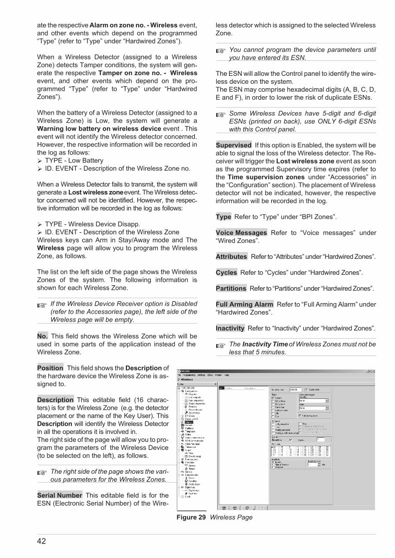
ate the respective Alarm on zone no. - Wireless event,
and other events which depend on the programmed
“Type” (refer to “Type” under “Hardwired Zones”).
When a Wireless Detector (assigned to a Wireless
Zone) detects Tamper conditions, the system will gen-erate the respective Tamper on zone no. - Wireless
event, and other events which depend on the pro-grammed “Type” (refer to “Type” under “Hardwired
Zones”).
When the battery of a Wireless Detector (assigned to a
Wireless Zone) is Low, the system will generate a
Warning low battery on wireless device event . This
event will not identify the Wireless detector concerned.
However, the respective information will be recorded in
the log as follows:
� TYPE - Low Battery
� ID. EVENT - Description of the Wireless Zone no.
When a Wireless Detector fails to transmit, the system will
generate a Lost wireless zoneevent. The Wireless detec-tor concerned will not be identified. However, the respec-tive information will be recorded in the log as follows:
� TYPE - Wireless Device Disapp.
� ID. EVENT - Description of the Wireless Zone
Wireless keys can Arm in Stay/Away mode and The
Wireless page will allow you to program the Wireless
Zone, as follows.
The list on the left side of the page shows the Wireless
Zones of the system. The following information is
shown for each Wireless Zone.
� If the Wireless Device Receiver option is Disabled(refer to the Accessories page), the left side of theWireless page will be empty.
No. This field shows the Wireless Zone which will be
used in some parts of the application instead of the
Wireless Zone.
Position This field shows the Description of
the hardware device the Wireless Zone is as-
signed to.
Description This editable field (16 charac-
ters) is for the Wireless Zone (e.g. the detector
placement or the name of the Key User). This
Description will identify the Wireless Detector
in all the operations it is involved in.
The right side of the page will allow you to pro-
gram the parameters of the Wireless Device
(to be selected on the left), as follows.
� The right side of the page shows the vari-ous parameters for the Wireless Zones.
Serial Number This editable field is for the
ESN (Electronic Serial Number) of the Wire-
less detector which is assigned to the selected Wireless
Zone.
� You cannot program the device parameters untilyou have entered its ESN.
The ESN will allow the Control panel to identify the wire-less device on the system.
The ESN may comprise hexadecimal digits (A, B, C, D,
E and F), in order to lower the risk of duplicate ESNs.
� Some Wireless Devices have 5-digit and 6-digitESNs (printed on back), use ONLY 6-digit ESNswith this Control panel.
Supervised If this option is Enabled, the system will be
able to signal the loss of the Wireless detector. The Re-ceiver will trigger the Lost wireless zone event as soon
as the programmed Supervisory time expires (refer to
the Time supervision zones under “Accessories” in
the “Configuration” section). The placement of Wireless
detector will not be indicated, however, the respective
information will be recorded in the log.
Type Refer to “Type” under “BPI Zones”.
Voice Messages Refer to “Voice messages” under
“Wired Zones”.
Attributes Refer to “Attributes” under “Hardwired Zones”.
Cycles Refer to “Cycles” under “Hardwired Zones”.
Partitions Refer to “Partitions” under “Hardwired Zones”.
Full Arming Alarm Refer to “Full Arming Alarm” under
“Hardwired Zones”.
Inactivity Refer to “Inactivity” under “Hardwired Zones”.
� The Inactivity Timeof Wireless Zones must not beless that 5 minutes.
42
Figure 29 Wireless Page

� Replacing Wireless Devices
To replace a Wireless detector (assigned to a Wireless
Zone): select the required Wireless Zone, then enter
the ESN of the new Wireless detector in the Serial
Number field.
� Enrolling Wireless Devices
To enrol a Wireless detector: select an empty Wireless
Zone, then enter the Wireless detector ESN in the Se-rial Number field.
� Unenrolling Wireless Devices
To unenrol a Wireless detector (assigned to a Wireless
Zone): select the required Wireless Zone then enter
000000 in the Serial Number field.
Outputs
Control panel Outputs no. 1, no. 2 and no. 3 are 3 A
double switching relays. The terminals for these Outputs
are:
� Output no. 1 = +N1, +A1, C1-NC1-NA1
� Output no. 2 = +N2, +A2, C2-NC2-NA2
� Output no. 3 = +N3, +A3, C3-NC3-NA3
The Control panel Outputs no. 4, no. 5 and no.6 are 1 A
Open-Collectors. The terminals for these Outputs are:
OC1, OC2 and OC3.
The Expander Outputs are 0.15 A Open-Collectors.
The terminals for these Outputs are OC1, OC2, OC3,
OC4, OC5 and OC6.
The Output Expander Buzzer 98 can be connected to
the terminal [OC6] via jumper 99 :
� 1ooo 3 = buzzer OFF (at default):
� 1//o 3 = the buzzer will sound when the terminal
[OC6] opens;
� 1o// 3 = the buzzer will sound when the terminal
[OC6] closes to Negative.
TheControl Panel Outputs and Expander Outputs can be as-sociated with Events that activate signalling devices (Sirens,
Flashers, etc.), or used to provide Operating/Trou-ble status and device control signals. They can
also be used to turn ON/OFF electrical appliances
at the Keypad or via telephone (Heating, Garden
sprinklers, etc.). The Outputs page will allow
you to program the Control Panel and Ex-pander Output parameters, as follows. The
table on the left side of the Outputs page
shows the Outputs. The number of available
Outputs depends on the system (refer to
“Configuration”). The following information
will be shown for each Output.
No. This field shows the Output ID number,
used in some parts of the application, instead
of the Output Description (refer to “Descrip-tion”).
Position This field shows the Description of the Out-put placement. This label can be edited on the Output
Expanders page.
Device This field shows the Address of the Output place-ment (Control Panel Outputs are indicated by a hyphen).
Ter. This field shows the Output terminal tag:
� RL1 = +N1, +A1, C1-NC1-NA1
� RL2 = +N2, +A2, C2-NC2-NA2
� RL3 = +N3, +A3, C3-NC3-NA3
Description This editable field (16 characters) is for the
Output label (e.g. the detector placement or the name of
the Key User). The Parameters on the right side of the
Outputs page can be programmed as follows.
Type The Output can be programmed as either Mono-stable (M) or Bistable (B).
Pol. The Output can be programmed as either
Normally Closed (NC) or Normally Open (NO).
� Type
Bistable This type of Output will activate when AT
LEAST ONE of its associated Events occurs, and will
stop when ALL of its associated Events end.
Monostable This typeofOutputwill activatewhenATLEAST
ONEof itsassociatedEventsoccurs,andwill stopwhen thepro-grammed ON Time expires (see “ON Time” below).
� Polarity
This programming field will allow you to program the
Output standby polarity .
Normally Open The electrical state during standby is:
[+N] terminals open; Positive signal (13.8V) on the [+A]
terminals; [C] terminals closed to their respective [NO]
terminals; [NC] and [OC] terminals open.
KYO320 PROGRAMMING 43
Figure 30 Outputs page

Normally Closed The electrical state during standby
is: Positive signal (13.8V) on the [+N] terminals; [+A]
terminals open; [C] terminals closed to their respective
terminals [NC]; [NO] terminals open; [OC] terminals
closed to Negative.
� Attributes
Reserved This Attribute will allow the User to acti-vate/stop the Output from the Keypad or via telephone
(refer to “Activating Outputs” under “KEYPAD
OPERATIONS" in the PROGRAMMING FROM KEYPAD
MANUAL, and to the “OPERATIONS VIA TELEPHONE”
section in the USER MANUAL).
� Reserved Outputs CANNOT be associated withthe Events on the Events-Actions page.
� When you exit a programming session via PC, Mo-dem or Keypad, the Reserved Outputs will restoreto the status they were in before the programmingsession started.
Output followed This field will allow you to associate
the selected Output with another Output. The selected
Output will track the specified Output (i.e. be activated
by the same Events, and perform the same Actions).
If you DO NOT want the selected Output to track an-other Output, you must select “None” in this field. An
Output that is programmed to track another Output will:
� activate when the specified Output activates;
� restore to standby when the “tow” Output restores to
standby.
� If you program an Output to track another Output,you will not be able to associate it with the Eventson the Events-Actions page.
Supervised If the system has been duly set up, this At-tribute will allow the system to monitor the Output for short
circuits and interrupted connections (refer to NOTE).
� This Attribute can be selected for Outputs no. 1, 2and 3 .
NOTE: Terminal [+A] must be wired in accordance with
the instructions in the “Supervised Outputs” paragraph
(refer to the “INSTALLATION” section under “Con-necting Signalling Devices”), otherwise, the system will
be unable to signal short circuits and interrupted connec-tions on the Supervised Outputs.
� Associated Timer
This section will allow you to associate a Timer with the
Output. The Output can be activated ONLY by the se-lected Timer (refer to “Time Programmer - Timer”).
� When the Timer window expires, the Output will re-store to standby, even if the conditions that gener-ated the event are still present.
� Times
This section will allow you to set the On/Off Times of
the Output.
� The ON Time and OFF Time can be set for Mono-stable Outputs only.
ON Time This is the maximum activation time of the
Output.
Valid entries:
� 0.2 through 25.4 seconds, in 0.2-second steps (for
sec. option)
� 1 through 127 minutes, in 1-minute steps (for Min.
option)
Default setting: 3 minutes
OFF Time This is the minimum OFF Time after restoral
of the Output. The Output will be unable to re-activate
until the programmed OFF Time expires.
Valid entries: 1 through 255 seconds, in 1-second steps.
Default setting: 3 minutes
44
... on set
... end
EVENT
... onset
... on standby
OUTPUTBistable
... onset
... on standby
OUTPUTMonostable
Half cycle
ON time OFF time
1st Cycle 2nd Cycle
the event ends here ifit is associated with a
Monostable Output
Figure 31 The Effect of the Oscillation and Cycle parameters on Bistable and Monostable Outputs

� Oscillation
Outputs with this attribute will remain active for the pro-grammed time, return to standby for the same amount
of time, and then reactivate. Oscillating Outputs can be
used to generate visual and audible signals (cause
LEDs to blink or buzzers to sound).
Oscillation parameters
Half Cycle This field will allow you to program the amount
of time the Output will be active, and the amount of time it
will be in standby status during Oscillation.
Valid entries: 200 msec (milliseconds) through 1400 msec
in 200 msec steps; If you set 0, the Output will not oscillate.
� Cycles
Monostable Outputs may continue to run the programmed
number of Cycles even after the triggering event has been
cleared. During each cycle, the Output will be active for the
programmed ON Time and will restore to standby for the
programmed OFF Time. If a Half Cycle has been pro-grammed, the Output will oscillate in accordance with the
Half Cycle parameters (during the ON Time).
This field will allow you to set the number of Output
Cycles, as follows.
� The parameters in the Cycles section can be set forMonostable Outputs only.
Cycles This field will allow you to set the number of cy-cles the Output must run.
Valid entries: 1 to 31 Cycles (1 Cycle is set at default).
Timeless If this option is enabled, the Output will run
an unlimited number of cycles. In which case, the Out-put cycles can be interrupted ONLY by Partition Reset
or Control Panel Reset.
! DO NOT associate Outputs with the Timeless attrib-
ute with NON Restorable-NON Spot, Spot and Spe-
cial events, as these events cannot be stopped.
� Events
The Events button will allow you to view the Events
that activate the selected Output.
Partitions
Each Partition consists of a group of zones that the
system manages independently (Virtual Control
Panel). Each Partition can be programmed with its
own Codes, Timers, Actions and Parameters.
This system manages 32 Partitions. You can setup
the Partitions in the BPI Zones andWireless pages.
The layout of the Partitions page is as follows.
No. This field shows the Partition ID number, used
in some parts of the application instead of the De-scription (e.g. for Telephone Access).
Description This field is for the Partition Label (16
characters). The Description will identify the Parti-tion in all the operations it is involved in.
Entry Time This field will allow you to set the Partition
Entry Time. Violation of an Armed Entry Delay Zone
will trigger the programmed Entry Time.
The Partition Entry Time will be signalled by:
� the Entry time on partition event for the Partition;
� an audible signal from the Partition Keypads.
An Alarm will not be generated if the violated Partition is
Disarmed before the Entry time expires.
Exit Time This field will allow you to set the Partition
Exit Time. Violation of an Armed Exit Delay Zone will
trigger the programmed Exit Time.
If violation ends before the Exit time expires, the Zone
will not generate an Alarm.
The Partition Exit Time will be signalled by:
� the Exit time on partition event for the respective
Partition;
� an audible signal on the Partition Keypads.
Last Exit Time This field will allow you to set the Last
Exit Time. Violation of an Armed Last Exit Zone will
trigger the programmed Last Exit Time of its Partition.
This feature will allow the system to Arm as soon as the
programmed Last Exit Time expires. Valid entries for
Entry, Exit and Last Exit Times:
0 minutes and 0 seconds through 59 minutes and 55
seconds, in 5-second steps. If you enter a higher value,
it will be converted automatically to the maximum ad-missible value. If you enter a value that is not a multiple
of 5 seconds, it will be rounded off to the nearest 5-sec-ond step. Default setting: 1 minute.
Partition Code This field is for the Partition User
Code. When a Partition-related event occurs, the Digital
Communicator will send the respective Partition Code
to the telephone numbers with the Send Always option
Disabled (refer to “Digital Communicator”).
The Partition Code is useful in shared Security system
applications (for example, in an apartment building or
Shopping Mall, etc.) where it is necessary to identify the
Partition in Alarm status rather than the system (the
KYO320 PROGRAMMING 45
Figure 32 Partitions page

Partition Code will identify the Partition whereas the
Customer Code will identify the system).
� If the reporting format supports 4 digits, only thefirst four digits will be sent.If the protocol does not support hexadecimal digits(A, B, C, D and F), they will be converted to 0.
� When operating with SIA or SIA on B-NET reporting for-mats, the Digital Communicator will send the respectiveCustomer Code (refer to "Digital Communicator").
Negligence Time Under normal circumstances,
Users Arm their systems with a certain regularity, if this
does not occur, it may be due to Negligence on the
User’s behalf or may mean that the User is in difficulty
(due to serious illness, accident or delinquency), in
which case, this feature will prompt the Central station
operator to take the necessary action.
This programming field will allow you to set the Negli-gence Time. If the system is not Armed within the pro-grammed time, the Control panel will generate the Neg-ligence on Partition event.
Valid entries: 1 through 60000 minutes (41 days and 16
hours) in 1-minute steps.
Invalid entries (over 60000 minutes) will generate an er-ror message.
If this option is left at default (0), Negligence will not be
signalled.
Negligence will be signalled by:
� the Event negligence on partition event — relevant
to the Partitions the Zone is assigned to.
Auto-Arm Timeout This field will allow you to program
the Automatic Arm pre-alert period.
For example, if the Timer is set to Arm Partition no. 1 at
17:45 p.m. with a 15-minute Auto-Arm Timeout, the
system will generate the Autoarming warning parti-tion no. 1 event at 17.30, and will signal the start of the
pre-alert period. The pre-alert signal will warn anyone
on the premises that the system is about to Arm. During
the pre-alert phase the system will accept Overtime Re-quests. If no valid Code is entered during this period,
the system will Arm as programmed.
The event will end when the programmed Auto-Arm
Timeout expires or when the Partition Arms after an
Overtime request.
Valid entries: 0 through 240 minutes, in 1-minute steps.
If you set 0, there will be no warning.
If you enter a higher value than the maximum, it will be
converted automatically to 240 minutes.
Auto-Arm Signal If this option is enabled (�) for the Par-tition (Enabled at Default), the Partition Keypads will emit
an audible signal (beep) during the entire pre-alert period.
Patrol Time This programming field will allow you to
set the Patrol Time. If the system is disarmed by a User
Code with the Patrol attribute (refer to “Patrol Code” un-der “Keypad Codes — User”), it will rearm automatically
when the programmed Patrol Time expires.
Valid entries: 0 through 254 minutes in 1-minute steps.
Default setting: 10 minutes.
Autoreset on Arming If this option is enabled (at de-fault), the system will Reset Partition Alarms each
time it is Armed (refer to “Reset Partition Alarms” under
“Keypad Codes — Code Types”).
Timer Associated Arming This option provides the
system with an Arm command filter. If a Timer window
is associated with a Partition, the system will carry out
commands to Arm the Partition concerned ONLY when
the respective Timer window is running (refer to
“Scheduler - Timers”).
Timer Associated Disarming This option provides
the system with a Disarm command filter. If a Timer win-dow is associated with a Partition, the system will carry out
commands to Disarm the Partition concerned ONLY when
the respective Timer window is running (refer to “Scheduler -
Timers”). However, if the Disarm with Alarm in memory
option is enabled, it will be possible Disarm the Partition in the
event of violation (Alarm or Tamper) during the Timer window.
Confirm alarm If this option is enabled and a zone trig-gers Alarm status, the system will start the respective
Confirm alarm timer window but will not generate a
Partition burglar alarm. If another zone alarm occurs
(triggered by a different zone) while the Timer window is
running, the system will generate a Partition alarm.
Confirm alarm timer This field will allow you to pro-gram the Confirm alarm timer window (necessary
when the Confirm alarm option is enabled) which deter-mines the Partition alarm delay. This feature will allow
the system to trigger a Partition alarm only when two or
more zone alarms (triggered by different zones) occur
during the running window.
Disarm with Alarm in memory If this option is en-abled, it will be possible to override the Partition Timer
and Disarm the Partition in the event of violation (Alarm
or Tamper in memory), even when the Timer window is
running (refer to Timer associated Disarming). This
feature will allow users to disarm Timer controlled Parti-tions which under normal circumstances (unviolated)
cannot be disarmed.
Partition Armed Voice Message This option will al-low you to select the voice message which will answer
status enquiries over-the-phone (DTMF) when the Par-tition concerned is armed.
Partition Disarmed Voice Message This option will
allow you to select the voice message which will answer
status enquiries over-the-phone (DTMF) when the Par-tition concerned is disarmed.
� The "Partition Armed" voice message will apply toall arming types: Stay; Away, Stay 0 Delay.
46

Telephone
The Telephone page will allow you to program:
� the Telephone numbers for the Digital Communica-tor, Dialler, Auxiliary Communicator and Teleservice
facilities;
� Telephone line parameters;
� the Answering Machine parameters.
The layout of the Telephone page is as follows.
No. This field shows the Telephone ID number. This
number will be used instead of the Description (User la-bel) in some parts of the application.
Telephone Number This editable field (maximum 20
digits) is for the Telephone number the system will call.
Valid entries: digits from 0 to 9, pound (#), star (*) and
comma (,). The comma can be used to insert pauses, for
example, between a switchboard number and a tele-phone number.
Description This editable field (maximum 16 characters)
is for the Telephone Number label (e.g. User Name). The
Description at default is [Tel. Number nnn] — (nnn repre-sents the ID number of the Telephone Number).
Used by This programming section will allow you to
assign the Telephone facilities:
� Dial. = Dialler
� Dig. = Digital Communicator
� Tel. = Teleservice
� Answer
The Answer section will allow you to program the Con-trol Panel answer mode.
� The Control Panel cannot answer incoming callswhen the Answering Machine or Teleservice func-tion is Disabled (refer to “Enable/DisableTeleservice” and “Enable/Disable An-swering Machine” in the USER’SMANUAL).
Rings This field will allow you to program the
number of rings the Control panel must allow
before answering an incoming call.
� If the Double call option is enabled, thenumber of Rings will be ignored (refer to“Double call” under “Teleservice”).
� Dialling
The Dialling section will allow you to program
the Control Panel Dialling mode.
Line Check If this option is Enabled, the sys-tem will supervise the telephone line.
The system will signal “Line down” (i.e. volt-
age on the [L.E.] terminals less than 3V for over 45 sec-onds) by:
� turning ON theG8
LED;
� generating the Line Trouble signal — an X (blinking)
above the i icon;
� generating the Telephone line trouble event.
The system will signal “Line restoral” (voltage on the
[L.E.] terminals more than 3V for 15 seconds) by:
� turning OFF theG LED (i.e. unless there are other
faults);
� clearing the Trouble signal;
� terminating the Telephone line trouble event.
This option must be Disabledwhen the Control Panel is
not connected to a telephone line, otherwise, the Tele-
phone line trouble event will be signalled persistently.
Start Telephone Call Delay This field will allow you to
program a delay between the start of the Alarm and the
first outgoing Alarm call. This delay will give the User
time to verify the Alarm and stop outgoing calls in the
event of false Alarm.
� The Start Telephone Call Delay will be applied tothe first Telephone number in the Call Queue.
Valid entries: 0 through 1200 seconds (20 minutes), in
1-second steps.
Default setting: 0 seconds.
Tone Check If this option is enabled, the Control panel
will check for the dialling tone before dialling. If the dial-ling tone is not detected during the programmed Time-out, the Control panel will hang-up and retry.
High-Low Volume If listen-in and and remote 2way
Speaker system (Teleassistance) is enabled it is possi-ble to choose between High or Low Volume.
KYO320 PROGRAMMING 47
Figure 33 Telephone page
8 TheG LED signals several different types of Trouble events. If the signal is due to telephone line trouble, theKeypad (in View Trouble Mode) will show the Tel.Lin.Failure message.

Pulse Dial This Control Panel has been set up to dial
in DTMF (Touch-tone). If this option is enabled, the
Control Panel will dial in Pulse.
Tones This option will allow you to select the country.
The selected country will allow the Control panel to op-erate properly on the local terrestrial line.
� If the country is not listed, select EUROPEANGENERIC.
� If the Control panel is unable to operate properlyusing EUROPEAN GENERIC, you must Disable
the Tone check.
� Answering Machine
The Answering Machine function will allow you to re-cord a Voice Answer Message. The message will be
played each time the Control Panel answers a call after
the programmed number of Rings.
� The Answering Machine function can be En-abled/Disabled by the User (refer to “Enable/Dis-able Answering Machine” in the USER’SMANUAL).
If the Teleservice function is also Enabled, the Control
Panel will emit a beep, wait approximately 6 seconds
for the Modem to respond (if connected) and, if no re-sponse is detected, will play the Message. If the An-swering Machine Message has not been recorded the
Control panel will emit a beep.
The layout of the Answering Machine window is as fol-lows.
Answer Message This field will allow you to select the
Answering Machine Voice Message (refer to “Voice
Messages”).
Message Repetitions This field will allow you to pro-gram the number of times the message must be played.
Valid entries: 0 through 255;
Default setting: 3.
Replay Pause This field will allow you to program a
pause between Answer Message announcements.
Valid entries: 1 through 254, in 1-second steps;
Default setting: 5 seconds.
PIN Timeout This field will allow you to program the
time the User will have to enter the User Code (with re-
mote Telephone Access) on the telephone keypad.
Valid entries: 1 through 254 seconds, in 1-second steps
Default setting: 30 seconds.
� Only Codes no. 132 to 195 can access the ControlPanel via telephone (refer to the “Codes” paragraph).
DTMF Tone Timeout This field will allow you to pro-gram the time (in seconds) the User will have to enter
the Command after Code acceptance. The User must
start entering the command before the Timeout ends,
otherwise, the Control Panel will end the call. Valid en-tries: 1 through 254 seconds, in 1 second steps. Default
setting: 30 seconds.
Dialler
The Dialler page will allow you to define up to 50 Ac-tions. Each Action can be associated with one or more
Events in the Events-Actions page. The Actions will
signal via Telephone the start and/or end of their asso-ciated Events. Each Dialler Action can send a Voice
Message to a maximum of 32 Telephone numbers.
Message Queue The Dialler will not end the call until
all the messages destined for the connected telephone
number have been sent. This feature reduces call time
and costs.
� Events will not be queued when the Call success-ful number option is Enabled (refer to “Options”under “Dialler”).
The layout of the Dialler page is as follows.
� The Dialler parameters apply to all the numbers inthe Dialler book.
� Dialler book
The Dialler book will allow you to assign up to 32 Tele-
phone numbers from the General book (refer to “Tele-
phone”) to the Dialler function.
No. This is the Identifier number (1 through 32) which
represents the Telephone number in the Actions win-
dow. This Identifier number DOES NOT
CORRESPOND to the Telephone Number ID number
in the General Phonebook.
Telephone Number This field will allow you to select
the Telephone Number the Dialler must call.
1. Click on the field you wish to program.
2. Click again on the same field: the program will dis-
play the Telephone Numbers in the General
Phonebook.
3. Select the required Telephone Number.
48
Figure 34 Answering Machine window
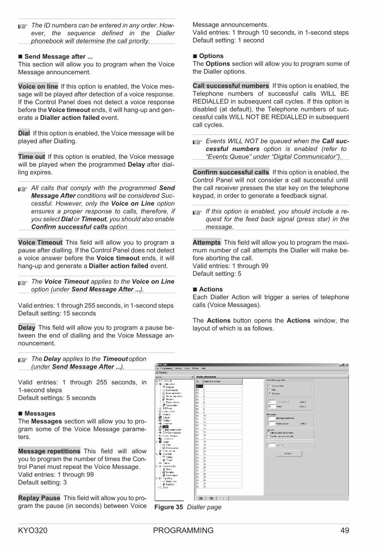
� The ID numbers can be entered in any order. How-ever, the sequence defined in the Diallerphonebook will determine the call priority.
� Send Message after ...
This section will allow you to program when the Voice
Message announcement.
Voice on line If this option is enabled, the Voice mes-sage will be played after detection of a voice response.
If the Control Panel does not detect a voice response
before the Voice timeout ends, it will hang-up and gen-erate a Dialler action failed event.
Dial If this option is enabled, the Voice message will be
played after Dialling.
Time out If this option is enabled, the Voice message
will be played when the programmed Delay after dial-ling expires.
� All calls that comply with the programmed Send
Message After conditions will be considered Suc-cessful. However, only the Voice on Line optionensures a proper response to calls, therefore, ifyou select Dial or Timeout, you should also enableConfirm successful calls option.
Voice Timeout This field will allow you to program a
pause after dialling. If the Control Panel does not detect
a voice answer before the Voice timeout ends, it will
hang-up and generate a Dialler action failed event.
� The Voice Timeout applies to the Voice on Line
option (under Send Message After ...).
Valid entries: 1 through 255 seconds, in 1-second steps
Default setting: 15 seconds
Delay This field will allow you to program a pause be-
tween the end of dialling and the Voice Message an-
nouncement.
� The Delay applies to the Timeout option(under Send Message After ...).
Valid entries: 1 through 255 seconds, in
1-second steps
Default settings: 5 seconds
� Messages
The Messages section will allow you to pro-gram some of the Voice Message parame-ters.
Message repetitions This field will allow
you to program the number of times the Con-trol Panel must repeat the Voice Message.
Valid entries: 1 through 99
Default setting: 3
Replay Pause This field will allow you to pro-gram the pause (in seconds) between Voice
Message announcements.
Valid entries: 1 through 10 seconds, in 1-second steps
Default setting: 1 second
� Options
The Options section will allow you to program some of
the Dialler options.
Call successful numbers If this option is enabled, the
Telephone numbers of successful calls WILL BE
REDIALLED in subsequent call cycles. If this option is
disabled (at default), the Telephone numbers of suc-cessful calls WILL NOT BE REDIALLED in subsequent
call cycles.
� Events WILL NOT be queued when the Call suc-
cessful numbers option is enabled (refer to“Events Queue” under “Digital Communicator”).
Confirm successful calls If this option is enabled, the
Control Panel will not consider a call successful until
the call receiver presses the star key on the telephone
keypad, in order to generate a feedback signal.
� If this option is enabled, you should include a re-quest for the feed back signal (press star) in themessage.
Attempts This field will allow you to program the maxi-mum number of call attempts the Dialler will make be-fore aborting the call.
Valid entries: 1 through 99
Default setting: 5
� Actions
Each Dialler Action will trigger a series of telephone
calls (Voice Messages).
The Actions button opens the Actions window, the
layout of which is as follows.
KYO320 PROGRAMMING 49
Figure 35 Dialler page

No. This field shows the Action identifier number. This
number is to be used on the Events-Actions page, to
associate the Action with the Events.
! If you select this field, the Action will take absolute Pri-ority over all other Actions. Therefore, if one of its asso-ciated Events occurs, the Control Panel will suspend
any ongoing Dialler calls, and will call the telephone num-bers of the Priority Action.
To assign Priority (!): double click on the corresponding cell.
� Only one Dialler Action can take priority.
1 ... 32 Numbers 1 through 32 represent the Dialler
Telephone Numbers (refer to the No. column in the
Dialler book on the Dialler page).
To assign an Action to a Dialler Telephone Number,
double click on the corresponding cell (Y indicates that
the Action will generate a call to the corresponding Dial-ler Telephone Number.
� Each time you click on a Telephone Number cell (1through 32), the application will display the com-plete Telephone Number and corresponding De-scription (User Label).
All If this option is enabled, the Control Panel will call
all the Telephone numbers for the corresponding Ac-tion. If this option is disabled (at default). The Dialler will
call associated Telephone numbers until one call is suc-cessful. To enable (Y) this option, press ENTER or dou-ble click on the respective cell.
Message 1-2-3-4-5 This option will allow you to setup
the Voice Messages (refer to “Voice Messages” and
“Preset Messages” for further information).
Description This editable field is for the Action label.
Hide This button will allow you to hide the Telephone
number columns (1 through 32), and Voice Message
columns (Messages 1 through 5).
Events This button will allow you to view all
the Events that generate the selected Action.
Digital Communicator
The Digital Communicator will allow you to
define up to 100 Actions. Each Action can be
associated with one or more Events in the
Events-Actions page, and will signal (via
telephone to Central Stations, etc.), the start
and/or end of its associated Events.
Each Digital Communicator Action can trans-mit a distinct groups (8 Telephone numbers
per group), (e.g. a Trouble signal to the In-staller and Central Station).
Event Queue The Digital Communicator will
not end the communication until all the events
destined for the connected service have been transmit-ted. This feature reduces communication time, and call
costs.
� Events will not be queued for Telephone numberswhich are associated with Reporting formats withthe Voice feature.
The layout of the Digital Communicator page is as fol-lows.
no. This ID number (1 through 8), corresponds to the
Telephone number Identifier in the Actions window.
This Identifier number DOES NOT CORRESPOND to
the Telephone Identifier number in the General
Phonebook.
Telephone Number to call
This field will allow you to select the Telephone Num-bers for the Digital Communicator (from the General
Phonebook on the Telephone page).
Protocol This field will allow you to select the Re-porting format.
This Control Panel supports the Reporting formats
shown Table 4. (refer to “Communication Protocols” in
the APPENDIX).
The first five protocols are also available with the Voice
feature.
� Both the Control panel and Central Station must beable to manage voice communications, otherwise,Reporting formats with the Voice feature cannot beused.
Once the digital transmission has been completed, the
Control Panel will open the Voice channel, and the
Central Station operator will be able to open a Talk/lis-ten session.
50
Figure 36 Dialler settings window

The system Users will be able to communicate with the
Central Station operator via the VOX-REM Microphone
and Speaker boards (refer to “K3/VOX2 Voice Cards” in
the “APPENDIX”).
The Voice channel will remain open for the pro-grammed time (refer to “2-way audio”), or until the Cen-tral Station operator ends the session.
� Reporting formats with the Voice feature transmitONLY one event per call.
Reporting formats with the Voice feature should only be
used when absolutely necessary. For events that do not
require the Voice channel feature, use the same Re-porting format without the Voice feature, as follows:
1. Select the same Telephone number (Central Sta-tion number) in two programming fields on the Digi-
tal Communicator page.
2. Select the Reporting format “without Voice” in one
programming field, and the same Reporting format
”with Voice” in the other.
3. In the Digital Communicator Actions window:
for events that DO NOT REQUIRE a Voice channel
— select the Central Station that supports the Re-porting format “without Voice”;
for events that REQUIRE a Voice channel— select the Central Station that supports the Re-porting format “with Voice”.
System Code This field is for the System ID Code
(usually assigned by the Central Station). The System
Code format (number of digits and valid range) de-pends on the selected Reporting Format (refer to the
CUSTOMER CODE column in the Table 4).
Send Always If this option is Disabled, the Digital
Communicator will transmit the Partition Code when
the Action is triggered by a Partition-related event, and
will transmit the System Code when the Ac-tion is triggered by any other type of event. If
this option is Enabled, the Digital Communi-cator will transmit the System Code regard-less of the type of event.
Attempts This field will allow you to program
the maximum number of Call attempts for each
Telephone Number.
Valid entries: 1 through 99
Default setting: 3
2-way audio This option will allow you to
program the 2-way audio session time.
Valid entries: 0 through 180 seconds (3 min-utes), in 1-second steps.
Default setting: 30 seconds
Actions The Actions button opens the Ac-
tions window.Each Digital Communicator
Action comprises two sub-actions, each of which sends
a Code Call to a series of telephone numbers.
No. This field shows the Action ID number. This num-ber is to be used on the Events-Actions page to asso-ciate the Action with the Events.
! If this option is enabled, the Action will take absolute
Priority over all other Actions. Therefore, if one of its as-sociated Events occurs, the Control Panel will suspend
any ongoing Digital Communicator calls, and will call
the telephone numbers of the Priority Action. To assign
Priority (!): double click on the corresponding cell.
� Only one Digital Communicator Action can havepriority.
Code This field is for the Event Code. The Event Code
format depends on the selected Reporting Format (re-fer to the EVENT CODE column in the Table 4) (for
CESA and Pulse protocol only).
The preset Event Codes of TELIM Reporting Format
CANNOT be edited (refer to “Reporting Formats” in the
“APPENDIX”). Therefore, the Communicator will trans-mit the preset Event Code.
The preset Event Codes of CONTACT ID, SIA and SIA
over B-NET can be edited (refer to “Reporting Formats” in
the “APPENDIX”). If the cell is left empty, the Communicator
will transmit the preset Event Code, otherwise, it will transmit
the edited Event Code. For SIA and SIA over B-NET Re-porting Formats accept 2 uppercase letters only.
1 ... 8 These Numbers represent the Digital Communi-cator Telephone Numbers that will be called when the
Action occurs.
The Digital Communicator Numbers are represented by
their ID Number (see No. column on the Digital Commu-
nicator page). To select/deselect a Digital Communicator
Number, double click on the respective cell (YES indicates
that the Digital Communicator Number will be called).
KYO320 PROGRAMMING 51
Figure 37 Digital Communicator page

� If you associate an Action with a Digital CommunicatorNumber which transmits in CONTACT ID, TELIM,CESA or SIA Reporting Format, any other DigitalCommunicator Numbers, assigned to the Actionconcerned, must transmit in the same Reporting For-mat.
All If this option is Enabled, the Control Panel will call
all the numbers when the corresponding Action occurs.
If this option is Disabled (at default), the Control Panel
will terminate the call cycle after the first successful call.
To enable (Y) this option, press ENTER or double click
on the respective cell.
Description This editable field is for the Action label.
Events This button will allow you to select the Events
that will trigger the Action.
CONTACT ID If the selected telephone number is asso-
ciated with CONTACT ID, it is possible to associate this re-
porting format automatically to priority events, by selecting
and confirming CONTACT ID (see the Figure 38).
DEFAULT SIA If the selected telephone num-
ber is associated with SIA, it is possible to associ-
ate this reporting format automatically to priority
events, by selecting and confirming SIA (see the
Figure 38).
Voice Messages
This function is provided by the K3/VOX2 Voice
Board (accessory item). The K3/VOX2 will allow
the Control Panel to manage up to 64 Voice
Messages with programmable quality and
length. The amount of message time available
depends on the sound quality of the messages,
and ranges from 3 minutes 48 seconds for high
sound quality, to 8 minutes 44 seconds for low
sound quality (refer to “K3/VOX2 Voice board” in
the “APPENDIX”).
� Message No. 63 can be used for the Memo func-tion (refer to “Memo” in the USER’S MANUAL) andMessage No. 64 for the Continuous Recordingfunction (refer to “Enable Continuous Recording”under “Options”). If the Home Memo and/or Contin-uous Recording facilities are not used, these mes-sages can be used for other purposes.
The Voice messages can be used for the:
� Zone status control
� Answering Machine message
� Dialler messages
� Memo function
� Continuous Recording function
� Voice Messages can be recorded and played atthe Keypad, as described in the KEYPADPROGRAMMING MANUAL.
The layout of the Voice Messages page is as follows.
No. This is the non-editable Message ID Number. This
number substitutes the Message Description in some
parts of the application.
52
Figure 38 Digital Communicator Actions window
REPORTING FORMAT TYPECUSTOMER CODE
digits (validity)
EVENT CODE
digits (validity)NOTES
ADEMCO/SILENT KNIGHT - Slow 10 baud Pulse
3/4 (0 ÷ F) ½ (0 ÷ F) 0 = A
ADEMCO/SILENT KNIGHT - Fast 20 baud Pulse
FRANKLIN/SESCOA/DCI/VERTEX - Fast 20 baud Pulse
RADIONICS - 40 baud Pulse
SCANTRONIC - 10 baud Pulse
CONTACT IDDTMF 4 (0 ÷ F)
See Event-Actions
Page0 = A
TELEMAX Pulse 3 (0 ÷ 9) 1 (0 ÷ 9)
TELIM Pulse 6 (0 ÷ 9) Pre-set
CESA FSK 5 (0 ÷ 9) 2 (0 ÷ 9)
SIA
SIA over B-NETLAN 4 (0 ÷ 9)
See Event-Actions
Page
Table 4 Digital Communicator Reporting Formats
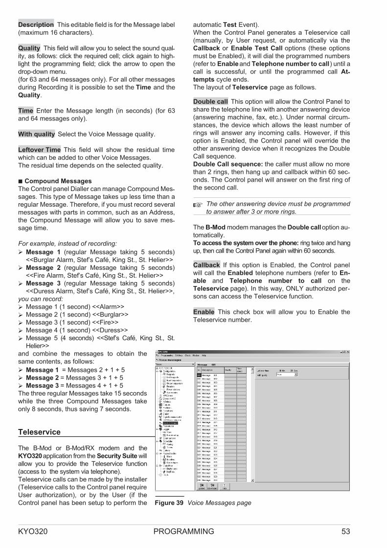
Description This editable field is for the Message label
(maximum 16 characters).
Quality This field will allow you to select the sound qual-ity, as follows: click the required cell; click again to high-light the programming field; click the arrow to open the
drop-down menu.
(for 63 and 64 messages only). For all other messages
during Recording it is possible to set the Time and the
Quality.
Time Enter the Message length (in seconds) (for 63
and 64 messages only).
With quality Select the Voice Message quality.
Leftover Time This field will show the residual time
which can be added to other Voice Messages.
The residual time depends on the selected quality.
� Compound Messages
The Control panel Dialler can manage Compound Mes-sages. This type of Message takes up less time than a
regular Message. Therefore, if you must record several
messages with parts in common, such as an Address,
the Compound Message will allow you to save mes-sage time.
For example, instead of recording:
� Message 1 (regular Message taking 5 seconds)
<<Burglar Alarm, Stef’s Café, King St., St. Helier>>
� Message 2 (regular Message taking 5 seconds)
<<Fire Alarm, Stef’s Café, King St., St. Helier>>
� Message 3 (regular Message taking 5 seconds)
<<Duress Alarm, Stef’s Café, King St., St. Helier>>,
you can record:
� Message 1 (1 second) <<Alarm>>
� Message 2 (1 second) <<Burglar>>
� Message 3 (1 second) <<Fire>>
� Message 4 (1 second) <<Duress>>
� Message 5 (4 seconds) <<Stef’s Café, King St., St.
Helier>>
and combine the messages to obtain the
same contents, as follows:
� Message 1 = Messages 2 + 1 + 5
� Message 2 = Messages 3 + 1 + 5
� Message 3 = Messages 4 + 1 + 5
The three regular Messages take 15 seconds
while the three Compound Messages take
only 8 seconds, thus saving 7 seconds.
Teleservice
The B-Mod or B-Mod/RX modem and the
KYO320application from the Security Suite will
allow you to provide the Teleservice function
(access to the system via telephone).
Teleservice calls can be made by the installer
(Teleservice calls to the Control panel require
User authorization), or by the User (if the
Control panel has been setup to perform the
automatic Test Event).
When the Control Panel generates a Teleservice call
(manually, by User request, or automatically via the
Callback or Enable Test Call options (these options
must be Enabled), it will dial the programmed numbers
(refer to Enableand Telephone number to call) until a
call is successful, or until the programmed call At-tempts cycle ends.
The layout of Teleservice page as follows.
Double call This option will allow the Control Panel to
share the telephone line with another answering device
(answering machine, fax, etc.). Under normal circum-stances, the device which allows the least number of
rings will answer any incoming calls. However, if this
option is Enabled, the Control panel will override the
other answering device when it recognizes the Double
Call sequence.
Double Call sequence: the caller must allow no more
than 2 rings, then hang up and callback within 60 sec-onds. The Control panel will answer on the first ring of
the second call.
� The other answering device must be programmedto answer after 3 or more rings.
The B-Mod modem manages the Double calloption au-tomatically.
To access the system over the phone: ring twice and hang
up, then call the Control Panel again within 60 seconds.
Callback If this option is Enabled, the Control panel
will call the Enabled telephone numbers (refer to En-
able and Telephone number to call on the
Teleservice page). In this way, ONLY authorized per-sons can access the Teleservice function.
Enable This check box will allow you to Enable the
Teleservice number.
KYO320 PROGRAMMING 53
Figure 39 Voice Messages page

� The application will assign the first four TelephoneNumbers in the General book (Telephone page)to the Teleservice function. If you do not wish touse the preset numbers, Disable the correspond-ing Enable option.
Telephone Number to call Select the Teleservice
Telephone Numbers from the General book on the
Telephone page.
� Disabled Telephone Numbers will not be called.
Customer Code This Code will allow the Central Sta-tion to identify the Control Panel.
� Any changes made to the Customer code on theTeleservice page will affect the Customer code inthe Customer Data window and vice versa.
Attempts This programming field will allow you to pro-
gram the maximum number of call attempts.
Valid entries: 1 through 99
At default: 8
� Enable Test Event
If this option is Enabled, the Control panel will make
regular Test Calls. The Test call confirms that the Con-
trol Panel is operating properly. If the Control panel fails
to transmit to the Central station for a long period, it may
mean:
— the system is operating properly but no events have
occurred or,
— there is a breakdown in transmissions.
If the Central station does not receive the Test Call at
the set time, it will be assumed that there is a break-
down in transmissions.
To set up the Test call, use the Test event and/or
Teleservice, as follows.
Enable Test Call If this option is Enabled, the Control
Panel will make the Test call at regular intervals, in accor-
dance with the First Testand Repeat test event settings.
� If the Enable Test Event is Disabled, theControl panel will not send the Test call.
Enable Test Event If this option is Enabled,
the Control panel will generate the Test event
in accordance with the First Test and Repeat
test event parameters.
If this option is Disabled (at default), the Test
event will be inhibited.
First Test This programming field is for the
date and time of the first Test.
� Subsequent Test calls depend on the Re-peat test event setting.
Repeat test event This programming field is
for the interval between Test calls.
Initialize If you are downloading a new Test setting to
the Control panel, you must select this button, other-wise the new setting will be ignored.
� If the entered date and time are prior to the currentdate and time on the computer, the Initialize buttonwill be inhibited. The Control Panel must be con-nected to the PC via serial port or telephone.
� Installer Maintenance
The Installer Maintenance section will allow you to
program the date and time of Installer Maintenance Re-quest signal.
The Installer Maintenance Requestwill be signalled by the:
� Installer Maintenance event;
� ON status of theG indicator on the keypad.
� The Trouble indicator G signals various Troubleevents. The Trouble details can be found on theLCD Keypads (in View Mode). If the trouble is re-lated to an Installer Maintenance Request, the re-spective message will be shown (see theDescription field in the Installer Maintenance
section).
The Trouble signal generated by the Installer Mainte-nance Request and Installer Maintenance will termi-nate when:
� the Teleservice page is downloaded;
� the Date and Time of Installer Maintenance are pro-grammed at the Keypad (refer to “Teleservice” in the
KEYPAD PROGRAMMING MANUAL).
To set up the Installer Maintenance Request — Enable
the Maintenance Request option and set the Date and
Time, as follows.
Date Enter the date of the Installer Maintenance Re-quest signal.
54
Figure 40 Teleservice page

Time Enter the time of Installer Maintenance Requestsignal.
Description Edit the message that will be shown on
Keypad (in View Mode) when an Installer MaintenanceRequest is received.
� Central Station Maintenance
The Central Station Maintenance section will allow
you to program the date and time of the MonitoringMaintenance Request signal.
The Monitoring Maintenance Request will be signalled
by the :
� Central station maintenance event;
� ON status ofG indicator on the keypad.
� The Trouble G indicator signals various Troubleevents. The Trouble details can be found on theLCD Keypads (in View Mode). If the trouble is re-lated to a Monitoring Maintenance Request, the re-spective message will be shown (refer to theDescription field in the Central station mainte-
nance section).
The Trouble signal generated by the Central stationmaintenance request and the Central station mainte-
nance event will terminate when:
� the Teleservice page is downloaded;
the Date and Time of Monitoring Maintenance are pro-grammed at the Keypad (refer to “Teleservice” in the
KEYPAD PROGRAMMING MANUAL).
You must Enable the Central Station Maintenance
option and set the Date and Time, as follows.
Date Enter the Date of the Central Station Mainte-nance Request signal.
Time Enter Time of the Central Station MaintenanceRequest signal.
Description Enter the message that will be shown
on the Keypad (in View Mode) when a Central Sta-tion Maintenance Request is received.
Log – Events setup
The Events setup page will allow you to select the
Events that will be recorded in the log, and those that
will be printed, as follows.
� The Event Printout is an accessory feature, andis provided by the optional K3/PRT2 Printer In-terface (refer to “K3/PRT2 Printer Interface” inthe APPENDIX).
No. This is the Event ID Number.
Description This is the Event label.
Enabled Select the Events that will be recorded in the
log.
Printer Select the Events that will be printed.
Colour For a best reading of the Logger it is possible to
change the colour events.
� In the Logger menu there is the Wiew window. Inthis window you find the "Export" key. This key al-lows yow to export the Logger as a text file. Soyou can edit it by software as "Excel" or others. TheLogger export can be done in several way, usingmany type of filters.
Events-Actions
The Events-Actions page determines how the system
will operate.
The Table in the Events-Actions page will allow you to
associate the Events (managed by the Control Panel)
with the Output, Digital Communicator and Dialler Ac-
tions, as follows.
No. This is the Event ID Number.
Description This is the Event label:
� the round brackets show the label of the device (Key-
pad, Reader, etc.) that is associated with the “Object”
(Zone, Code, Key, etc.) that generated the event;
� the square brackets show the Description of the “Object”
(Zone, Code, Key, etc.) that generated the event.
� The events shown depend on the selected detaillevel (see “Events Details”).
KYO320 PROGRAMMING 55
Figure 41 Event-Actions page

Output The ON column is for the ID number of the Out-put that must activate when the respective Event occurs
(refer to No. column on the Outputs page).
Enter 0 if the event is not to activate any Output.
� You can select the required Output by double click-ing the corresponding cell in the Output column.
Dig. Comm. The ON column is for the ID Number of
the Actions the Digital Communicator must generate
when the Event concerned starts (see No. column in
the Actions window on the Digital Communicator
page) . The OFF column is for the ID Numbers of the
Actions the Digital Communicator must generate when
the Event concerned ends (see No. column in the Ac-
tions window on the Digital Communicator page).
Enter 0 in the ON or OFF column if the Digital Commu-nicator for NO Actions.
� You can associate the Digital Communicator Ac-tion with the Event by double clicking the corre-sponding cell in the Dig. Comm. ON or Dig.
Comm. OFF column.
Dialler The ON column is for the ID Numbers of the Ac-tions the Dialler must generate when the Event con-cerned starts (see No. column in the Actions window
on the Dialler page).
The OFF column is for the ID Numbers of the Actions
the Dialler must generate when the Event concerned
ends (see No. column in the Actions window on the
Dialler page).
Enter 0 in the ON or OFF column if the Dialler is not to
generate any Actions.
� You can associate the Dialler Action with the Eventby double clicking the corresponding cell in theDialler ON or Dialler OFF column.
Contact ID Code Event Code default value with Con-
tact ID protocol. If teleservice needs this value can be
changed.
SIA N Code Event Code default value with SIA proto-
col (New event). If teleservice needs this value can be
changed.
SIA O Code Event Code default value with SIA proto-
col (Restore). If teleservice needs this value can be
changed.
� Telephone action priority
Priority Actions will override all other Actions in the call
queue.
The Digital Communicator Action marked with an excla-
mation mark (refer to “Actions” in the “Digital Communi-
cator” section) has priority over all other Telephone
Actions. The Dialler Action marked with an exclamation
mark (refer to “Actions” in the “Dialler” section) has pri-
ority over all other Telephone Actions except the priority
Action set for the Digital Communicator.
� The priority Telephone Actions are useful in situa-tions that require quick intervention, such as Medi-cal emergency and Duress.
� Colours
The Colours button will allow you to assign a colour to
each group of events.
� Events Details
The Events Details button will allow you to filter the
events that will be shown, as follows.
Highlight programmed events If you Enable this op-tion, Events with AT LEAST ONE associated Action (on
an Output, Digital Communicator or Dialler) will be dis-played in bold face.
Show only programmed events If you Enable this
option, only the Events with AT LEAST ONE associated
Action (on an Output, Digital Communicator or Dialler)
will be shown.
None If you Enable this option, AllEvents will be displayed.
Zone If you Enable this option, all the Zone events will
be shown. If this option is Disabled, the Zone events will
be grouped into the following *Global* Events:
� Alarm on zone *Global*
� Alarm on zone Wireless *Global*
� Tamper on zone *Global*
� Tamper on zone Wireless *Global*
� Bypass zone *Global*
� Bypass zone Wireless *Global*
� Real time of zone *Global*
� Real time of zone Wireless *Global*
Partition If you Enable this option, all the Partition events
will be shown. If this option is Disabled, the Partition
events will be grouped in the following *Global* Events:
� Fire alarm on partition *Global*
� 24h alarm on partition *Global*
� Burglar alarm on partition *Global*
� Generic alarm on partition *Global*
� Tamper alarm on partition *Global*
� Generic+Tamper alarm on partition *Global*
� Away alarm on partition *Global*
� Stay alarm on partition *Global*
� Not Ready-to-arm partition *Global*
� Extended not Ready-to-arm partition *Global*
� Partial arming partition *Global*
� Global arming partition *Global*
� Disarming partition *Global*
� Exit time on partition *Global*
� Entry time on partition *Global*
� Autoarming warning partition *Global*
� Memory alarm on partition *Global*
� Memory tamper on partition *Global*
56

� Alarm stop on partition *Global*
� Reset on partition *Global*
� Chime on partition *Global*
� Event negligence on partition *Global*
� Event delinquency on partition *Global*
� Memory alarm on partition (VDS) *Global*
� Panic alarm on partition (VDS) *Global*
� Tamper alarm on partition (VDS) *Global*
Digital Key If you Enable this option, all the Key events
will be shown. If this option is Disabled, the Key events
will be grouped in the following *Global* Event:
� Valid Key *Global*
Output If you Enable this option, the Supervised Out-
put events will be shown. If this option is Disabled, the
Supervised Output events will be grouped in the follow-
ing *Global* Event:
� Tamper on supervised output *Global*
Keypad If you Enable this option, the Keypad events
will be shown. If this option is Disabled, the Partition
events will be grouped in the following *Global* Event:
� Block keypad *Global*
� Recognized user code on Keypad *Global*
FAP Key If you Enable this option, the Super Key events
will be shown. If this option is Disabled, the Super Key
events will be grouped in the following *Global* Event:
� Super key *Global*
Keypad Codes If you Enable this option, all the Code
events will be shown. If this option is Disabled, the Code
events will be grouped in the following *Global* Event:
� Recognized user code *Global*
User Events If you Enable this option, all the Custom-
ized Events will be shown. If this option is Disabled, the
Customized Events will be grouped in the following
*Global* Event:
� User event *Global*
Timer If you Enable this option, all the Timer events will
be shown. If this option is Disabled, the Timer Events
will be grouped in the following *Global* Event:
� Timer *Global*
Reader If you Enable this option, all the Reader events
will be shown. If this option is Disabled, the Reader
Events will be grouped in the following *Global* Event:
� Key present on reader *Global*
� You CANNOT associate Actions with Global
Events as they re not single events but representgroups of Events that would not otherwise beshown.
Show events concerning The drop-down menu in
this section (opened by clicking the arrow) will allow you
to filter the details of the Events (Enabled in the Show
Details section) that will be viewable, as follows.
� All: ALL the events concerning the Enabled Event
Types will be viewable.
� Zone: ONLY the events concerning the specified
Zone will be viewable (the Zone ID Number must be
entered in the small box).
� Partition: ONLY the events concerning the specified
Partition will be viewable (the Partition ID Number
must be entered in the small box).
� System: ONLY the System events will be viewable.
� Digital Key: ONLY the events concerning the speci-fied Key will be viewable (the Key ID Number must
be entered in the small box).
� Output: ONLY the events concerning the specified
Supervised Output will be viewable (the Output ID
Number must be entered in the small box).
� Keypad: ONLY the events concerning the specified
Keypad will be viewable (the Keypad ID Number
must be entered in the small box).
� FAP Key: ONLY the events concerning the specified
SuperKey will be viewable (the SuperKey Number
must be entered in the small box).
� Keypad Codes: ONLY the events concerning the
specified Keypad Code will be viewable (the Keypad
Code ID Number must be entered in the small box).
� User events: ONLY the events concerning the speci-fied Customized Event will be viewable (the Customized
Event ID Number must be entered in the small box).
� Timer: ONLY the events concerning the specified
Timer will be viewable (the Timer ID Number must be
entered in the small box).
� Reader: ONLY the events concerning the specified
Reader will be viewable (the Reader ID Number
must be entered in the small box).
� Clear
The Clear button will allow you to delete the Output,
Digital Communicator and Dialler Actions.
Select the Type of Action to be deleted (Output, Digital
Communicator or Dialler), then click OK to confirm the
operation.
� Find
This tool will allow you to find Events quickly. You must
enter part, or the entire Event label (Description), then
click the button. The application will go to the first
Event which contains the entered word or combination
of words. Click the button again to continue.
� Event Description
This section describes the conditions that generate,
and terminate each event.
KYO320 PROGRAMMING 57

Zone Events Table 5 shows Zone events associated
with Zone alarm and Zone Tamper events.
� The conditions which terminate Zone events(ENDSWHEN ...column) arevalidONLYwhen theZoneEvent is NOT associated with a Monostable Output.
If the Zone event is associated with a Monostable Out-put, the event will end when the Output OFF Timeout
expires, even if the conditions that triggered the event
are still present. In all other cases, the event will end
when the conditions clear (see Figure 42).
A Zone event can be restored to standby by:
� changing the status (Armed/Disarmed) of a Partition
the Zone is associated with;
� running Alarm Reset from a Keypad (the entered
User Code and Keypad must be jointly enabled on a
Partition the Zone is associated with);
� running Alarm Stop from the Keypad (the entered
User Code and Keypad must be jointly enabled on a
Partition the Zone is associated with);
� Using a valid Digital Key/Card at a Reader (both Digi-tal Key and Reader must be jointly Enabled on a Par-tition the Zone is associated with).
Partition Events Table 6 shows the Partition Events.
The Partition Events encase the Zone Events (Fire, 24h,
Burglar, etc.). Each Zone event will in turn generate a
Partition event (on the Partition the Zone is associated
with). The Partition event will not terminate until all the
Zone events end, as follows:
� The conditions which terminate Partition Events(ENDS WHEN ... column) are valid ONLY whenthe Partition Event is NOT associated with a Mono-stable Output.
Zone Events which are associated with a Monostable
Output will not terminate until the Output OFF Timeout
has expired (see Figure 42).
Partition Events can be restored to standby by:
� changing the Partition status (Armed/Disarmed);
� running Alarm Reset from a Keypad (the entered
User Code and Keypad must be jointly enabled on
the Partition concerned);
� running Alarm Stop from the Keypad (the entered
User Code and Keypad must be jointly enabled on
the Partition concerned)
� Using a valid Digital Key/Card at a Reader (both Digi-tal Key and Reader must be jointly enabled on the
Partition concerned).Control Panel Events
Table 7
shows the Control panel Events. The Control panel
events comprise all the Zone Events (Fire, 24h, Burglar,
etc.) but are totally independent of the Partitions. Con-trol panel events will be generated when the events
they comprise occur, and will not terminate until all the
events they comprise have ended.
� The conditions which terminate the Control PanelEvents (ENDS WHEN ... column) are valid ONLYwhen the Control Panel Event is NOT associatedwith a Monostable Output.
Control Panel Events associated with Monostable Out-puts will not terminate until the Output OFF Timeout has
expired (see Figure 42).
Control Panel Events can be restored to standby by:
� running Alarm Reset from a Keypad (the entered
User Code must be enabled for Control Panel Reset
— refer to “Keypad codes - Codes types”);
� running Alarm Stop from a Keypad (the entered
User Code must be enabled for Stop alarms — re-
fer to “Digital keys”);
� using a Digital Key/Card at a Reader (the Digital Key/Card
must be enabled for Stop alarms, refer to “Digital
keys”).Generic Events
These are Control
Panel-generated warnings (e.g. Power Failure).
58
EVENT OCCURS WHEN... ENDS WHEN...
0001
0280
Alarm on
zone no.
... the zone detects Alarm conditions9
... the zone restores to standby status
0281
0344
Alarm on
zone no. –
Wireless
... the Wireless zone detects Alarm10
condi-tions
... the Wireless zone restores to standby
0345
0624
Tamper on
zone no.
... the zone detects Tamper conditions ... Tamper conditions are no longer presenton the zone
0625
0688
Tamper on
Zone no. –
Wireless
… the Wireless Zone detects Tamper con-ditions
... Tamper conditions are no longer presenton the Wireless zone
Table 5 Zone Events —
9 The conditions that trigger Alarm and Tamper status on Hardwired Zones depend on the settings programmedon the BPI Zones page.
10The conditions that trigger Alarm and Tamper status on Wireless Zones depend on the settings programmed onthe dd page.

� The conditions which end a Generic Event(ENDS WHEN ... column) are only valid when theGeneric Event is NOT associated with a Mono-stable Output.
If a Generic Event is associated with a Monostable Out-put, it will not terminate until the Output-OFF Timeout
has expired (even if the trouble clears before); in all
other cases it will terminate when the trouble has been
cleared (see Figure 43).
Generic Events can be restored to standby by:
� running Alarm Reset from a Keypad (the entered
User Code must be enabled for Control Panel Reset
— refer to “Keypad codes - Codes types”);
KYO320 PROGRAMMING 59
... alarm
... standby
ZONE
... onset
... on standby
MonostableOUTPUT
ON timeOFFtime
... onset
... end
ZoneEVENT
ON timeOFFtime
... onset
... standby
Partition/PanelEVENT
Figure 42 Zone, Partition and Control Panel event operation — when associated with Monostable Outputs
EVENT STARTS WHEN... ENDS WHEN...
0689
0720
Fire alarm on
partition no.
...a Fire Zone — associated with the Parti-tion detects Fire Alarm conditions
…all events generated by Fire Zones — as-sociated with the Partition restore tostandby
0721
0752
24h alarm on
partition no.
...a 24h Zone — associated with the Parti-tion detects Alarm conditions
...all events generated by 24h Zones — as-sociated with the Partition restore tostandby
0753
0784
Burglar alarm
on partition no.
...a Burglar Zone (Instant,Entry delay,En-try path, Exit delay, Last exit) — associ-ated with the Partition detects Alarmconditions
...all events generated by Burglar Zones— associated with the Partition restore tostandby
0785
0816
Generic alarm
on partition no.
...a Zone (any type) — associated with thePartition detects Alarm conditions
... all Alarm events generated by Zones —associated with the Partition restore tostandby
0817
0848
Tamper alarm
on partition no.
...a Zone — associated with the Partitiondetects Tamper conditions
...all Tamper events generated by Zones— associated with the Partition restore tostandby
0849
0880
Generic+
Tamper alarm
on partition no.
...a Zone— associated with the Partition de-tects Alarm or Tamper conditions
...all Alarm and Tamper events generatedby Zones — associated with the Partitionrestore to standby
0881
0912
Away alarm on
partition no.
...the Generic+Tamper alarm on partition
event is triggered during Away mode...the Generic+Tamper alarm on partition
event ends
0913
0944
Stay alarm on
partition no.
...the Generic+Tamper alarm on parti-tion no. event is triggered during Staymode
...the Generic+Tamper alarm on parti-tion no. event ends
Table 6 Partition Events —

� running Alarm Stop from a Keypad (the entered
User Code must be enabled for Stop alarms — re-fer to “Digital keys”);
� using a Digital Key/Card at a Reader (the Digital
Key/Card must be enabled for Stop alarms — refer
to “Digital keys”).
Spot Events Spot events (see Table 9), such as Rec-
ognized User Code, are instant. Therefore, any action
undertaken on termination would serve no purpose.
Therefore:
� Bistable Outputs CANNOT be associated with Spot
Events;
� Dialler and Digital Communicator Actions CANNOT
be associated with restoral of Spot Events.
Customized Events These events (refer to Table 10)
can be set up to suit particular system requirements.
Each Customized Event is generated by the combined
effect of two other events (to be programmed in the
Customized event settings section). This feature is
useful in commercial buildings where, for security
reasons for example, two Codes must be entered
during a 2 minute window to open a protected door.
To set up a Customized Event — select the required
event, right click on the mouse, then click Define.
Refer to “Customized event settings” for the pro-gramming instructions.
Special Events The Special Events (refer to Table 11)
operate differently to other event types, as follows.
When a Memory alarm on partition (VDS) no. occurs:
� if the Partition is Armed in Stay mode, the Control
Panel will send the Digital Communicator action and
activate the respective Output;
� if the Partition is Armed in Away mode, the Control
Panel will send the respective Digital Communicator
call; if the Digital Communicator call is unsuccessful,
the Control Panel WILL activate the Output associ-ated with the Event.
� Dialler Actions CANNOT be associated with theMemory alarm on partition (VDS) and Tamper
alarm on partition (VDS) events.
� The i on the Keypad WILL NOT signal Dialler orDigital Communicator calls related to Panic alarm
on partition (VDS).
When a Tamper alarm on partition (VDS) no. occurs:
60
EVENT STARTS WHEN... ENDS WHEN...
0945 Fire alarm on
panel
...a Fire zone — regardless of its Partitiondetects Fire Alarm conditions
...All events generated by the Fire zones ofall Partitions restore to standby
0946 24h alarm on
panel
...a 24h zone — regardless of its Partitiondetects Alarm conditions
…all events generated by the 24h zones ofall Partitions restore to standby
0947 Burglar alarm
on panel
...a Burglar zone — regardless of its Parti-tion detects Alarm conditions (Instant, En-
try delay, Entry path, Exit delay, Last
exit)
...All events generated by the Burglarzones of all Partitions restore to standby
0948 Generic alarm on
panel
...a Zone — regardless of its Type and Par-tition detects Alarm conditions
…All events generated by the zones of allPartitions restore to standby
0949 Tamper alarm
on panel
...a Zone — regardless of its Partition de-tects Tamper conditions
...All Tamper events generated by thezones of all Partitions restore to standby
0950 Generic+
Tamper alarm
on panel
...a Zone — regardless of its Partition de-tects Alarm or Tamper conditions
…All Alarm and Tamper events gener-ated by the zones of all Partitions restore tostandby
0951 Tamper on Main
unit
...the Control Panel Tamper microswitch 3
or Seize microswitch 12 trip...the Tamper and Seize microswitches re-store
0952 Stop-alarms
jumper
... the STOP ALARMS jumper50 is inserted ...the STOP ALARMS 50 is removed
0953 Balanced
tamper
...the [ASB] terminal is unbalanced … the [ASB] terminal is balanced (groundedwith a 10000 ohm resistor)
0954
:
0956
Tamper on
supervised
output no.
...a Supervised Output is tampered11
...the Output tamper event ends
0957 Tamper BPI
readers
...the Proximity reader Tamper microswitch95 or Seize microswitch 87 trips
...the Proximity reader Tamper and Siezemicroswitches restore
0958 Tamper BPI
input expanders
...the Tamper microswitch 101 or Seizemicroswitch 96 of an Input Expander withthe same BPI bus Address trips
...the Tamper and Seize microswitches ofall Input Expanders restore, and NO two Ex-panders have the same BPI bus address
12
Table 7 Control panel events —

� if the Partition is Armed in Stay mode, the Control Panel
will send the respective Digital Communicator call but
WILL NOT activate the Output associated with the Event;
� if the Partition is Armed in Away mode, the Control
Panel will send the respective Digital Communicator
call; if the Digital Communicator call is unsuccessful,
the Control Panel WILL activate the Output associ-ated with the Event.
� The Dialler Actions CANNOT be associated withthe Tamper alarm on partition (VDS) no.Custom-ized Event Settings
KYO320 PROGRAMMING 61
EVENT STARTS WHEN... ENDS WHEN...
0959 Tamper keypads ...the Keypad Tamper microswitch 75 orSeize microswitch 79 trips, or there are atleast two Keypads with the same BPI busAddress
...the Tamper and Seize microswitches ofall Keypads restore, and NO two Keypadshave the same BPI bus Address
12
0960 keypadTamper
LED
...the Keypad Tamper microswitch 75 orSeize microswitch 79 trips, or there are atleast two Keypads with the same BPI busAddress
...the Tamper and Seize microswitches ofall Keypads restore, and NO two Keypadshave the same BPI bus Address
12
0961 Tamper output
expanders
...the Output Expander Tamper microswitch101 or Seize microswitch 96 trips, or thereare at least two Output Expanders with thesame BPI bus Address
...the Tamper and Seize microswitches ofall Output Expanders restore, and NO twoOutput Expanders have the same BPI busAddress
12
0962 Tamper power
stations
...the Tamper microswitch or Sieze TamperMicroswitch switch of a Power Supply Sta-tion is tripped
...the Tamper and Snatch switches of allPower Supply Stations are closed
0963 Tamper wireless
device
...the Tamper switch or Snatch switch of aVectorRX Receiver is tripped
...the Tamper and Snatch switches of allVectorRX Receivers are closed
Table 7 Control panel events
... low
... charge
BATTERY
... onset
... on standby
MonostableOUTPUT
ON timeOFFtime
... onset
... end
Low batteryEVENT
OFFtime
ON time
Figure 43 Operations of Generic Events associated with Monostable Outputs
EVENT STARTS WHEN... ENDS WHEN...
0964 Warning readers ...an enrolled Reader does not respond tothe Control Panel
...ALL Readers respond to the ControlPanel
0965 Warning BPI
input expander
...an enrolled Input Expander does not re-spond to the Control Panel
...ALL Input Expanders respond to the Con-trol Panel
0966 Warning
keypads
...an enrolled Keypad does not respond tothe Control Panel
...ALL Keypads respond to the ControlPanel
0967 Missing LED
Keypad
.an enrolled LED Keypad does not respondto the Control Panel
ALL LED Keypads respond to the ControlPanel
0968 Warning output
expanders
...an enrolled Output Expander does not re-spond to the Control Panel
...ALL Output Expanders respond to theControl Panel
0969 Warning power
stations
...an enrolled Power Supply Station doesnot respond to the Control Panel
....ALL Power Supply Stations respond tothe Control Panel
Table 8 Generic Events (continued on next page) —

62
EVENT STARTS WHEN... ENDS WHEN...
0970 Warning
wireless
devices
...the VectorRX Receiver does not respondto the Control Panel
...The VectorRX Receiver responds to theControl Panel
0971 False key ...a false Key/Card is used at a Reader ...ALL false Keys/Cards have been with-drawn from the Readers
0972 Warning fuse +F ...fuse blows ...fuse is replaced
0973 Warning fuse
+B1
...fuse blows ...fuse is replaced
0974 Warning fuse
+B2
...fuse blows ...fuse is replaced
0975 Warning fuse
+B3
...fuse blows ...fuse is replaced
0976 Warning fuse
+B4
...fuse blows ...fuse is replaced
0977 Warning fuse
+B5
...fuse blows ...fuse is replaced
0978 Warning fuse
BPI1
...fuse blows ...fuse is replaced
0979 Warning fuse
BPI2
...fuse blows ...fuse is replaced
0980 Warning fuse
KEYBUS
...fuse blows ...fuse is replaced
0981 Warning mains
failure
...Mains power has been off for the pro-grammed Timeout (refer to "Options")
...Mains power is restored
0982 Warning low
battery
...Battery voltage drops below 11.4V ...Battery voltage is restored to 12.3V
0983 Warning power
trouble
...a Battery fails the Dynamic Test (refer to"Connecting the Power supply" under"INSTALLING THE KYO320"), or fuse60blows
...Battery meets the Dynamic Test require-ments, or fuse 60 is replaced
0984 Warning mains
failure on Power
station
...the programmed Timeout expires (refer to"Power stations" under “Configuration”). TheTimeout will start when the Control panel de-tects failure of the Mains supply — to one ofthe BPI Bus Power Supply Stations.
...Mains power is restored to ALL the BPIBus Power Supply Stations
0985 Warning low
battery on
Power station
...the Battery Voltage of a BPI Power SupplyStation drops below 11.4V
...the Battery voltage of ALL BPI PowerSupply Stations restores to 12.3V
0986 Warning power
trouble on
Power station
...the Battery of a BPI Bus Power SupplyStation fails the Dynamic test, and there-fore, is unable to feed and ensure properfunctioning of the peripherals; or the PowerSupply Station polarity inversion fuse blows
...the Batteries of ALL the BPI Bus PowerSupply Stations pass the Dynamic test, orALL the Power Supply Station polarity in-version fuses are replaced
0987 Battery not
connected on
Power station
...the voltage of a Power station batterydrops below 10.2 V
the voltage of ALL the Power station batter-ies rises above 10.2V
0988 Battery charger
trouble on
Power station
...the output voltage of a Power stationpower supply module is 0.5 V above or be-low the preset value
11
...the output voltage of ALL the Power sta-tion power supply modules is 0.5 V aboveor below the preset value
0989 Switching not
connected on
Power station
...the output voltage of a Power stationpower supply module is 0.5 V above thepreset value
...the output voltage of ALL the Power sta-tion power supply modules is 0.5 V below orequal to the preset value
0990 Short circuit
output 1/2/3 on
Power station
...the current draw of a Power station outputis over 1.8 A
...the current draw of ALL the Power stationoutputs is over 1.8 A
Table 8 Generic Events (continued on next page) —

KYO320 PROGRAMMING 63
EVENT STARTS WHEN... ENDS WHEN...
0991 Battery low
memory
…2 years have passed since the lastReset
Battery Memory expired operation...the Reset Battery Memory operation isdone (refer to "Reset Warning Lithium" un-der "KEYPAD OPERATIONS" in thePROGRAMMING FROM KEYPADMANUAL)
0992 Warning low
battery on
wireless device
...the battery of at least one Wireless Sen-sor is low
...the last Wireless sensor has closed andALL Wireless Sensor batteries are charged
0993 Memory tamper
BPI device
...the Control panel detects one of the fol-lowing Events: Tamper BPI readers , Tam-per BPI input expanders, Tamper
keypads, Tamper output expanders,Tamper power station
...the Control Panel Resets
0994 Memory
balanced tamper
...Balanced tamper event is detected ...the Control Panel Resets
0995 Memory tamper
on main unit
...Tamper on Main unit event is detected ...the Control Panel Resets
0996 Memory false key ... False key event is detected ...the Control Panel Resets
0997 Memory tamper
supervised
output
...at least one Tamper on supervised out-
put event is detected...the Control Panel Resets
0998 Lost wireless
zone
...at least one of the Wireless Sensors of aSupervised Wireless zone fails to send avalid signal during the Supervision Time
...ALL Wireless Sensors send valid signalsduring the Supervision Time
0999 Warning generic ...at least one of the following events occurs:Stop-alarms jumper, Warning fuse +F,Warning fuse +F1, Warning fuse +B1,Warning fuse +B2, Warning fuse +B3,Warning fuse +B4, Warning fuse +B5,Warning fuse +BPI1, Warning fuse +BPI2,Warning fuse KEYBUS, Warning mains
failure, Warning low battery, Warning
mains failure on Power station, Warning
low battery on Power station, Warning
power trouble on Power station, Battery
not connected on Power station, Battery
charger trouble on Power station,
Switching not connected on Power sta-
tion, Short circuit output ½/3 on Power
station, Warning power trouble, Battery
Low Memory, Warning low battery on
wireless device, Installer maintenance,
Central Station maintenance, Telephone
line trouble; or the Control panel cannot findthe Voice board, the Control Panel clock iswrong (because the microprocessor hasbeen reset), the Control Panel has been pro-grammed from the PC
...ALL the listed events clear or, the Controlpanel finds the Voice board; the ControlPanel clock is set properly; the Reset Pro-
gramming from PC operation is done; theReset lith. batt. operation is done
1000 Installer
maintenance
…the Control panel clock reaches the Timeand Date programmed in the Installer main-tenance section on the Teleservice page
...the Teleservice page is downloaded orthe Date and Time for Installer Mainte-nance are programmed from a Keypad
1001 Central station
maintenance
...the Control panel clock reaches the Time andDate programmed in the Central station Main-
tenance section on the Teleservice page
...the Teleservice page is downloaded orthe Date and Time for Central station main-tenance are programmed from a Keypad
Table 8 Generic Events —

64
EVENT STARTS WHEN... ENDS WHEN...
1002 Standard
time/Summer
time changed
...the Enable automatic update standard
time/summer time option is enabled and:the Control panel clock reaches 02.00hours on the last Sunday in March (switchto daylight saving time) or,at 03.00 hours on the last Sunday in Octo-ber (switch back to standard time)
...the [Upd.leg.sum.time] message isshown on a keypad display in View Troublemode
1003
1034
Not
Ready-to-arm
partition no.
...the Partition Disarms AND:at least one of the Extended not
Ready-to-Arm Command Zones associatedwith the Partition detects Alarm conditions OR,at least one of the Zones of the Partition detectsAlarm conditions and the Zone IS NOT:— Bypassed or being Tested— an Exit delay or Last exit zone
— Autobypassable or Autobypass with
reset unbypass or Delayed and esti-mated on ready to arm (the event may betriggered with a delay of up to 2 seconds)
...ALL the Zones listed in the “STARTSWHEN” field restore to standby (the eventmay take up to 2 seconds to end)
1035(0595-0610)
1066
Partial arming
partition no.
...the Partition Arms in Stay Mode with ZeroDelay
...the Partition Arms in Away Mode or Dis-arms
1067
1098
Global arming
partition no.
…the Partition Arms in Away Mode ...the Partition Arms in Stay Mode or StayMode with Zero Delay
1099
1130
Disarming
partition no.
...the Partition Disarms ...the Partition Arms in Away Mode or StayMode or Stay with Zero Delay Mode
1131
1162
Exit time on
partition no.
...the Partition Arms in Stay or Away Mode ...the Partition Output Time expires
1163
1194
Entry time on
partition no.
...one of the Entry delay Zones belongingto the Partition detects Alarm conditionsand the Partition is Armed in Stay or AwayMode
...the Partition Input Time expires or thePartition Disarms
1195(0675-
0690)
1226
Autoarming
warning
partition no.
…the Control panel signals the start of theprogrammed Auto-Arm Timeout prior to Au-tomatic Arming of the Partition
...the Partition Arms or an Overtime Re-quest is made for the Partition
1227
1258
Memory alarm
on partition no.
...the Generic alarm on partition no.
Event occurs...the Partition Resets
1259(0707-
0722)
1290
Memory tamper
on partition no.
...the Tamper alarm on partition no. Eventoccurs
...the Partition Resets
1291
1790
Valid key no. ...a Key/Card is used at a Reader ...the Key/Card is removed from the Reader
1791
1822
Key present on
reader no.
...a valid Key/Card is used at the Reader ...the Key/Card is removed from the Reader
1823
1854
Valid Key on
Partition no.
... a valid Key/Card is inserted/held near aKeypad
...the Key/Card is removed from the Reader
1855
1886
Alarm stop on
partition no.
...a Stop Alarms request is made using aUser Code enabled for the Partition
...the Control panel exits the Stop Alarms
phase
1887 Alarm stop on
panel
…a Panel Alarm Stop request is made ...the Control panel exits the Panel Alarm
Stop phase
Table 8 Generic Events —

Setup the Customized Event, as follows.
Event 1 Enter the ID Number of the first event (associ-ated with the Customized event), or double click the
Event 1 field and select the event from the Table.
Event 2 Enter the ID Number of the second event (as-sociated with the Customized event), or double click the
Event 2 field and select the event from the Table.
� Enter 0 in the Event 1 and Event 2 fields, if theCustomized event is not required.
NOT If this option is enabled, the Event logic will
CHANGEOVER.
For example, if the NOT option is enabled for an Alarm
on zone event, the event will START when the zone
RESTORES TO STANDBY, and END when the zone
SIGNALS ALARM STATUS, instead of vice versa.
� The NOT option cannot be enabled for Spot Events,and for NON-Spot events with the AND Operator.
Window This parameter determines the period within
which the associated events (Events 1 and 2) must oc-cur. If these events do not occur during the pro-grammed Window, the system will not generate the
Customized event.
Disable the NONE option then enter the required value.
Valid entries: 1 through 13106 seconds (3 hours, 38
minutes and 26 seconds) in 1 second steps.
� The Customized Event can be associated withSpot events (which end almost instantly), andNON-Spot events (which have a duration).If you associate two Spot events with the Custom-ized Event, you MUST program the Window in or-der to provide the Spot events with a “virtual” end.The “virtual” end of Spot events will occur when theWindow expires.
KYO320 PROGRAMMING 65
EVENT STARTS WHEN... ENDS WHEN...
1888
2167
Bypass zone no. ...the Zone is bypassed ...Zone no. is restored
2168
2231
Bypass zone no.
– Wireless
...the Wireless Zone is bypassed ...the Wireless Zone is restored
2232 Telephone line
trouble
...the Telephone Line voltage is less than3V for 45 seconds. If the Telephone line
check is disabled (refer to "Telephone"),the event cannot be generated
...the Telephone Line voltage is higherthan 3V for 45 seconds
2233 Error printer …the Printer is either Disconnected; Im-properly connected to the Printer interface;OFF or Not in line (no paper, no ink/toner,blocked, etc.)
…the trouble clears
2234 Call queue full ...the 254th Telephone Action is queued ...there are no Telephone Actions in theCall Queue
2235
2298
Timer no. ...Timer no. switches ON (see Timer page) ... Timer no. switches OFF
2299
2578
Real time of
zone no.
...the voltage (resistance) on Zone no. en-ters the Alarm Range
...voltage (resistance) on Zone no. re-stores to Standby Range
2579
2642
Real time of
zone no. –
Wireless
...Wireless Zone no. is violated ...Wireless Zone no. returns to standby
Table 8 Generic Events —
EVENT STARTS WHEN... ENDS WHEN...
2643 Test ..the Control panel clock signals the Timeprogrammed on the Teleservice page
NOT ALLOWED!
2644
2675
Reset on
partition no.
...Alarms Reset is requested using a UserCode and Keypad jointly enabled for thePartition
NOT ALLOWED!
2676 Reset on panel ... Panel Reset is requested NOT ALLOWED!
Table 9 Spot Events (continued on next page)

66
EVENT STARTS WHEN... ENDS WHEN...
Super key [Fire]
[Keypad nnn]
…buttons Ì and Í on the Keypad arepressed simultaneously
NOT ALLOWED!
Super key
[Assistance]
[Keypad nnn]
...buttons P and p on the Keypad arepressed simultaneously
NOT ALLOWED!
Super
key [Police]
[Keypad nnn]
...buttons À and Á on the Keypad arepressed simultaneously
NOT ALLOWED!
Super key
[Key 1]
[Keypad nnn]
...button1 on the Keypad is pressed andheld down for 3 seconds
NOT ALLOWED!
Super key
[Key 2]
[Keypad nnn]
...button2 on the Keypad is pressed andheld down for 3 seconds
NOT ALLOWED!
Super key
[Key 3]
[Keypad nnn]
...button3 on the Keypad is pressed andheld down for 3 seconds
NOT ALLOWED!
2917
2948
SuperKey
on KeyFob
…the button of a Wireless key is pressedand held down for 2 seconds
NOT ALLOWED!
2949
2980
Chime on
partition no.
...a Zone with the Chime Attribute belong-ing to the Partition detects Alarm conditionswhen the Partition is Disarmed
NOT ALLOWED!
2981
3012
Event
negligence on
partition n.
… the Negligence Time expires NOT ALLOWED!
3013
3044
Event
delinquency on
partition no.
...the Inactivity Time expires NOT ALLOWED!
3045
3092
Block
Keypad no.
...the Keypad locks NOT ALLOWED!
3093
3287
Recognized
user code no.
....O,o, E,A,B,C orD is pressed af-ter entry of a valid User Code PIN
NOT ALLOWED!
3288
3335
Recognized
user code on
Keypad no.
...a Valid User Code PIN is entered at theKeypad
NOT ALLOWED!
3336
3367
Recognized
user code on
Partition no.
...a Valid User Code PIN is entered for thepartition
NOT ALLOWED
3368(2078)
Invalid code ....O,o, E,A,B,C orD is pressed af-ter entry of an Invalid User Code PIN
NOT ALLOWED!
3369 Recognized
installer code
…the Installer Menu is quitted NOT ALLOWED!
3370 Kissoff
recognized
...the Control panel detects the Kissofftone
11NOT ALLOWED!
3371(2081)
Start telephone
call
...the Control Panel engages the telephoneline
NOT ALLOWED!
3372 Teleservice
requested
...the Control Panel answers a Teleservicecall
NOT ALLOWED!
3373 Start
Teleservice
...the Teleservice connection is generatedafter recognition of the Installer PIN
NOT ALLOWED!
3374 Dialler action
OK
...a Dialler call is successful NOT ALLOWED!
3375 Action on digital
communicator
OK
...a Digital Communicator call — using aprotocol other than Contact ID — is suc-cessful
NOT ALLOWED!
Table 9 Spot Events (continued ...) —

The Window will start when either Event 1 or Event 2
occurs.
� The Window cannot restart until both events end(see Fig. 44: b3).
Operator Select the Operator (AND, OR or XOR) for
Events 1 and Event 2. The selected Operator deter-mines the operating mode of the Customized Event, as
follows.
� AND
The AND Operator will signal when BOTH the associ-ated events start. The AND Operator depends on the
event types (NON-Spot and/or Spot), and on whether or
not the Window has been programmed, as follows.
� Event 1 and Event 2 NON-Spot, NO Window
The system will generate the Customized Event, when
Event 1 AND Event 2 start (see Fig. 44: a1 and a3).
The system will end the Customized Event when either
Event 1 OR Event 2 ends (see Fig. 44: a2 and a4).
� Event 1 and Event 2 NON-Spot, WITH Window
The system will generate the Customized Event when
Event 1 AND Event 2 BOTH start during the pro-grammed Window (see Fig. 44: b1 and b4).
The system will end the Customized Event when the
programmed Window expires (see Fig. 44: b2 and b5).
� One Spot Event and one NON-Spot Event, NO
Window
The system will generate the Customized Event when
the NON-Spot Event starts after the Spot Event (see
Fig. 44: c1) or, when the Spot Event starts after the
NON-Spot Event (see Fig. 44: c3).
The system will end the Customized Event when the
NON-Spot Event ends (see Fig. 44: c2 and c4).
� One Spot Event and one NON-Spot Event, WITH
Window
The system will generate the Customized Event when
the NON-Spot Event starts after the Spot Event during
the Window (see Fig. 44: d1) or, when the Spot Event
starts after the NON-Spot event during the Window
(see Fig. 44: d3).
The system will end the Customized Event when the
NON-Spot Event ends (see Fig. 44: d2 and d4).
� Event 1 and Event 2 Spot, NO Window
� If you apply the AND Operator to two Spot Events,you MUST program the Window.
� Event 1 and Event 2 Spot, WITH Window
The system will generate the Customized Event when
either one of its associated Events starts after the other
during the Window (see Fig. 44: e1).
The system will end the Customized Event when
the Window expires (see Fig. 44: e2).
� OR
The OR Operator will signal when ONE of the associ-ated events starts. The OR Operator depends on the
Event types (NON-Spot and/or Spot), and on whether
or not the Window has been programmed, as follows.
� Event 1 and Event 2 NON-Spot, NO Window
The system will generate the Customized Event when ei-
ther Event 1 OR Event 2 starts (see Fig. 45: a1 and a3).
KYO320 PROGRAMMING 67
EVENT STARTS WHEN... ENDS WHEN...
3376 Digital
communicator
OK
...a Digital Communicator call — using aprotocol other than Contact ID — is suc-cessful
NOT ALLOWED!
3377 Teleservice
action OK
...a Teleservice call is successful NOT ALLOWED!
3378 Dialler action
failed
...a Dialler call fails NOT ALLOWED!
3379 Action on digital
communicator
failed
...a Digital Communicator call — using aprotocol other than Contact ID fails
NOT ALLOWED!
3380 Digital
communicator
action failed
...a Digital Communicator call — usingContact ID protocol fails
NOT ALLOWED!
3381 B-NET
communication
Failed
... a Digital Communicator call — using SIAover B-NET via the B-NET Module
NOT ALLOWED!
3382 Teleservice
action failed
...a Test call or other user-requested ateleservice call fails
NOT ALLOWED!
Table 9 Spot Events —
EVENT STARTS WHEN... ENDS WHEN...
3383
3414
Customized
event no.
...the logic expression defined for the Cus-tomized Event is true
...the logic expression defined for the Cus-tomized Event is false
Table 10 Customized Events

The system will end the Customized Event when Event 1
AND Event 2 end (see Fig. 45: a2 and a4).
� Event 1 and Event 2 NON-Spot, WITH Window
� If you apply the OR Operator to two NON-SpotEvents, the Window will be uninfluential.
� One Spot Event and one NON-Spot Event, NO
Window
The system will generate the Customized Event when
either Event 1 OR Event 2 starts (see Fig. 45: b1, b2,
b4, b6 and b8).
The system will end the Customized Event when Event
1 AND Event 2 end (see Fig.45: b1, b3, b5, b7 and b8).
68
EVENT STARTS WHEN... ENDS WHEN...
3415 Memo present … a message is recorded on theAnswerphone
.....the message is played
3416 B-NET Module
Missing
… the Control panel cannot communicatewith the B-NET Module
... communication with the B-NET Modulerestores
3417 LAN Link
Missing
… the Control panel cannot communicatewith the LAN
... communication with the LAN restores
3418 IP Receiver
Missing
… the Control panel cannot communicatewith the IP Receiver
...communication with the IP Receiver re-stores
Table 11 Special Events —
Event 1
Event 2
Window
Event 1
Event 2
AND
AND
b)
c)
Event 1
Event 2
AND
d)
Event 1
Event 2
Window
AND
e)
Event 1
Event 2
Window
AND
a) 11 22 33 44
11 22 33
11 22 33 44
11 22 33 44
11 22
44 55
Figure 44 The AND Operator mode
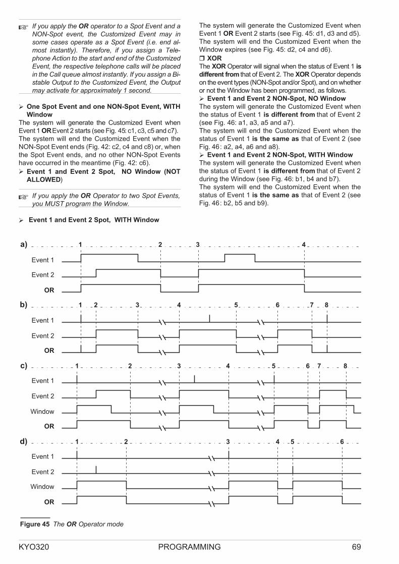
� If you apply the OR operator to a Spot Event and aNON-Spot event, the Customized Event may insome cases operate as a Spot Event (i.e. end al-most instantly). Therefore, if you assign a Tele-phone Action to the start and end of the CustomizedEvent, the respective telephone calls will be placedin the Call queue almost instantly. If you assign a Bi-stable Output to the Customized Event, the Outputmay activate for approximately 1 second.
� One Spot Event and one NON-Spot Event, WITH
Window
The system will generate the Customized Event when
Event 1 OREvent 2 starts (see Fig. 45: c1, c3, c5 and c7).
The system will end the Customized Event when the
NON-Spot Event ends (Fig. 42: c2, c4 and c8) or, when
the Spot Event ends, and no other NON-Spot Events
have occurred in the meantime (Fig. 42: c6).
� Event 1 and Event 2 Spot, NO Window (NOT
ALLOWED)
� If you apply the OR Operator to two Spot Events,you MUST program the Window.
� Event 1 and Event 2 Spot, WITH Window
The system will generate the Customized Event when
Event 1 OR Event 2 starts (see Fig. 45: d1, d3 and d5).
The system will end the Customized Event when the
Window expires (see Fig. 45: d2, c4 and d6).
� XOR
The XOR Operator will signal when the status of Event 1 is
different from that of Event 2. The XOR Operator depends
on the event types (NON-Spot and/or Spot), and on whether
or not the Window has been programmed, as follows.
� Event 1 and Event 2 NON-Spot, NO Window
The system will generate the Customized Event when
the status of Event 1 is different from that of Event 2
(see Fig. 46: a1, a3, a5 and a7).
The system will end the Customized Event when the
status of Event 1 is the same as that of Event 2 (see
Fig. 46: a2, a4, a6 and a8).
� Event 1 and Event 2 NON-Spot, WITH Window
The system will generate the Customized Event when
the status of Event 1 is different from that of Event 2
during the Window (see Fig. 46: b1, b4 and b7).
The system will end the Customized Event when the
status of Event 1 is the same as that of Event 2 (see
Fig. 46: b2, b5 and b9).
KYO320 PROGRAMMING 69
Event 1
Event 2
OR
b)
Event 1
Event 2
OR
c)
Event 1
Event 2
Window
OR
d)
Event 1
Event 2
Window
OR
a) 11 22 33 44
11 33 55
11 22 33 55
11 22
22
44
44 66 77 88
66 77 88
33 5544 66
Figure 45 The OR Operator mode

� The system WILL NOT generate the CustomizedEvent if the status of Event 1 is different from thatof Event 2 when the Window is not running (seeFig. 46: b3, b6 and b9).
� One Spot Event and one NON-Spot Event, NO
Window
The system will generate the Customized Event when
the status of Event 1 is different from that of Event 2
(see Fig. 46: c1, c2, c4, c7 and c9).
The system will end the Customized Event when the
status of Event 1 is the same as that of Event 2 (see
Fig. 46: c1, c3, c6 and c8), that is, unless the Spot Event
starts after the NON Spot event (see Fig. 46: c5).
� If you apply the XOR operator to a NON-Spot eventand a Spot Event, the Customized event may, insome cases, operate as a Spot Event (i.e. end al-most instantly). Therefore, if you assign a Tele-phone Action to the start and end of the CustomizedEvent, the respective telephone calls will be placedin the Call queue almost instantly. If you assign a Bi-stable Output to the Customized Event, the Outputmay activate for approximately 1 second.
� One Spot Event and one NON-Spot Event, WITH
Window
When calculating the XOR result of a Spot Event and a
NON-Spot Event, you must consider the Spot Event as
ending when the Window expires. Thus the Customized
Event will start when the status of Event 1 is diferent
from that of Event 2 during the Window (see Fig. 46: d1,
d4, d7 and d9).
The Customized Event will end when the status of the
Event 1 is the same as that of Event 2 (see Fig. 46: d2,
d5, d8 and d10).
70
Event 1
Event 2
Window
Event 1
Event 2
XOR
XOR
b)
c)
Event 1
Event 2
XOR
d)
Event 1
Event 2
Window
XOR
e)
Event 1
Event 2
Window
XOR
a) 11 22 44 55
11 22 44
11 33 44 66
11 22 33 44
11 22
33 55 77
22 55 77 88 99
66
33 5544 66
55 77 88 99 1100
33 66 77 88
66 88 99
Figure 46 The XOR Operator mode

� The system will not generate the Customizedevent, if the status of Event 1 is different from thatof Event 2, when the Window is not running (seeFig. 46: b3, b6 and b9).
� Event 1 and Event 2 Spot, NO Window (NOT
ALLOWED)
� If you apply the XOR Operator to two Spot Events,you MUST program the Window.
� Event 1 and Event 2 Spot, WITH Window
When calculating the XOR result of two Spot Events,
you must consider them as both ending when the Win-dow expires. In this way, the Customized Event will start
when the status of Event 1 is different from that of
Event 2 (see Fig. 46: e1, e3 and e5).
The Customized Event will end when the status of
Event 1 is the same as that of Event 2 (see Fig. 46: e2,
e4, and e6).
Scheduler - Arming
You can program the Scheduler to manage up to 16
Day Models (e.g. Weekday, Holidays, etc.), each with
up to 4 Arm and 4 Disarm operations per Partition.
! The Scheduler Actions will be ignored during
the programming session.
You can program the automatic Arm/Disarm parame-ters in the Arming page.
To create the Day Models — click the Models tab.
Partitions This field shows the Partition Descriptions
(to be programmed in the Partitions page).
1st Dis. / 2nd Dis. / 3rd Dis. / 4th Dis. These fields will
allow you to set up to 4 Disarm times for the corresponding
Partition.
Valid format: hh.mm — where hh represents the hour
(00 to 23) and mm represents the minutes (00 to 59).
For example, to set 7:45 a.m. — enter 07.45.
to set 5:45 p.m. enter 17.45.
If you enter an invalid value, the application will display
an error message.
1st Arm. / 2nd Arm. / 3rd Arm. / 4th Arm. These
fields will allow you to set up the automatic arming times
for the corresponding Partition.
1st Type / 2nd Type / 3rd Type / 4th Type These
fields will allow you to select the Arming Mode (Type)
for that Partition:
� A = Away
� S = Stay
� I = Stay with 0 Delay (Instant)
� Type Description
The Type Descr. button opens a window for the Model
labels (Weekday, Half-day, Holiday, Christmas holiday,
Summer Holiday, etc.).
No. This non-editable field shows the Model ID Number.
Description This field will allow you to edit the Model
label (maximum 16 characters).
� Models
The Models button will open the programming window
of the parameters described in this section.
Day This field will allow you to select the Day number.
Valid entries: 1 through 31 or Asterisk *.
� If you select an asterisk (*), the Day number (1
through 31) will be irrelevant for the Model.
� If you select a Day number, you will not be able to se-lect a Weekday.
� If you select an invalid number, the application will
automatically rectify it to last day of the month
concerned, when you click Download.
Month This field will allow you to select the Month.
KYO320 PROGRAMMING 71
Figure 47 Scheduler - Arming Page

� If you select an asterisk (*) the Month will be
uninfluential.
Year This field will allow you to select the Year.
Valid entries: 2005 through 2019:
� If you select an asterisk (*) the Year will be
uninfluential.
Interval You must select this field, if the corresponding
line indicates the Start of an Interval such as: Summer
holidays, Bank holiday week-end, Christmas, etc.
To program an Interval: select the start of the Interval on
one line and the end of the Interval on the following line,
then click the Start field. If the entry is valid the words
Start and Stop will be shown.
Valid entries: 1 through 31 (Day Number) or Monday,
Tuesday, etc. (Weekday).
� The Interval MUST Start and Stop within the samemonth.
Day of Week This field will allow you to select the Day.
� If you select an asterisk (*), the Day of the week will
be uninfluential.
� If you select a Weekday, you will not be able to spec-
ify the Day Number (1 through 31).
Type This field will allow you to select the Description
(label) of the Model.
� If you do not select a Description, the corresponding
Model will not be saved.
� You must select the Description of the Model on the
Start line of the interval. You cannot select the De-
scription on the Stop line as this field is automatic (*).
Sort Models This button will allow you to prioritize the
Models.
NOTE: Some days may belong to several Models. If
this occurs, the Scheduler will apply the Times of the
least frequent Model.
For example, the Christmas Holiday Model is applied
once a year, therefore, it will take priority over the
Weekday Model that is applied 5 days per week.
� Options
The Options button will open the programming window
of the parameters described in this section.
Max. Overtime Requests This option will allow you to
set the maximum number of Overtime Requests.
EXAMPLE: If a Timer controlled Partition is scheduled
to Arm at 17:45 — and the Overtime request period is
set at 60 minutes, and the Max. No. of Overtime re-quests is set at 2 — Arming can be postponed until
19:45 by two Overtime requests (17:45 + 2 x 60 min-utes), after which, Overtime requests will be ignored.
The maximum Overtime request is 180 minutes.
� If you select an invalid value, the application will rec-tify it to the highest accepted value.
� If you select 0, the program will rectify it to 1.
� Overtime Requests will affect the imminent Armingevent ONLY.
Example: If the 1st Arm event of a Partition is sched-uled for 12:45 and the 2nd Arm event is scheduled for
15:30, and the User makes four 1-hour Overtime Re-quests at 12.30 — with the intention of overlapping the
2nd Arm event (12:45 + 4 h = 16.45), the system will ig-nore the overlap and will Arm the Partition at 15.30 as
scheduled.
Overtime request This is the delay before a sched-uled Arming Time.
Example: If a Partition is scheduled to Arm at 17:45
and the Overtime Request is set at 60 minutes, and the
User makes an Overtime Request at 17.30, the Parti-tion will Arm at 18:45 (17:45 + 1 h) unless the User
makes further Overtime Requests in the meantime.
Valid entries: 0 through 60 minutes, in 1-minute steps.
� If you enter a value of over 60 minutes, it will be recti-fied automatically to 60 minutes.
� If you enter 0 minutes, Overtime Requests will be ignored.
� Examples
The following Models show: Weekday, Half-day, Bank
holiday, Summer holiday and Christmas holiday.
Weekdays This Model includes weekdays, regardless
of the Day number, Month and Year.
The Weekdays Model is an Interval and must be setup
on two lines.
On the upper line, select an asterisk (*) in the Day,
Month and Year fields, and Monday in the Day of
Week field.
On the lower line, select an asterisk (*) in the Day,
Month and Year fields, and Friday in the Day of Week
field.
Click the Interval field of the upper line: the words Start
and Stop will be shown.
Select Weekdays in the Type field.
DayMonth Year Interval Day of week Type
* * * Start Monday Weekdays
* * * Stop Friday *
Half-day This Model is for Half-day Closing.
Select an asterisk (*) in the Day, Month and Year fields,
and Saturday in the Day of Week field.
Select Half-day in the Type field.
DayMonth Year Interval Day of week Type
* * * * Saturday Half-day
Summer Holiday This Model is an Interval and must
be setup on two lines.
72

On the upper line, select the number of the first day of
the holiday period (e.g. 8) in the Day field, and the re-spective Month in the Month field (e.g. August).
Select an asterisk (*) in the Year and Day of Week
fields.
On the lower line, select the number of the last day of
the holiday period (e.g. 23) in the Day field, and the re-spective Month in the Month field (e.g. August).
Select an asterisk (*) in the Year and Day of Week
fields.
Click the Interval field of the upper line: the words Start
and Stop will be shown.
Select Summer holidays in the Type field.
DayMonth Year IntervalDay of week Type
8 August * Start * Summer Holiday
23 August * Stop * *
Christmas Holidays This Model can be setup in the
same way as the Summer Holiday period. However, if
the Christmas holiday period continues into the New
year (e.g. 24th December to 3rd January), it must be
setup on two blocks of 2 lines, as follows.
Days from the 24th to the 31st of December in the first
block
� Days from the 1st to the 2nd of January in the second
block.
DayMonth Year IntervalDay of week Type
24 Dec. * Start * ChristmasHolidays
31 Dec. * Stop * *
1 January * Start * ChristmasHolidays
2 January * Stop * *
Bank Holiday This Model is for Bank Holidays.
Select the Day number (e.g 20) and Month (e.g. April)
in the respective fields.
Select Bank holiday in the Type field.
DayMonth Year IntervalDay of week Type
20 April * * * Bank holiday
Model Priority Some days may belong to more than
one Model, therefore, the Scheduler will apply the
Times of the least frequent Model.
For example, Christmas Holiday Model — is applied
once a year, therefore, will take priority over the Week-
day Model that is applied 5 days per week.
Scheduler - Timers
You can define up to 16 Models, each with a maximum
of 4 different ON and 4 different OFF Times for each of
the 64 Control panel Timers.
Each Timer is associated with a Timer Event on the
Events-Actions page.
When the Timer triggers the ON signal, the correspond-
ing Event will occur (e.g. the Garden Sprinkler will turn
ON).
When the Timer triggers the OFF signal, the corre-sponding Event will be terminated (e.g. the Garden
Sprinkler will turn OFF).
The ON/OFF operations of each Timer will be recorded
in the log, as follows:
� Type: Timer ON or Timer OFF
� IDENT.: Timer Description
� TIME: Time and Date of the ON and OFF operations
The Timers can be programmed with the ON/OFF
Times of domestic appliances such as Garden Sprin-klers, Courtesy lights, Heating systems, etc., or with the
ACTIVE/INACTIVE Times of the system Outputs,
Codes and Keys.
� The user can enable/disable the Timers (refer to“En./Dis. Timers” in the USER MANUAL).
If a User disables a Timer during its programmed ON
Time, the corresponding Timer event will end.
If a User enables a Timer during its programmed ON
Time, the corresponding Timer event will start within the
minute.
Example: If a Timer — with a programmed ON Time of
21.00 to 24.00 — is enabled at 22:02:01 the corre-
sponding Timer event will be triggered at 22:03:00
The ENABLE/DISABLE operations of each Timer will
be recorded in the log, as follows:
� Type: Timer Enabled or Timer Disabled
� IDENT.: Timer Description
� USER: Keypad Description
� USER ID.: Code Description
� TIME: Time and Date of the ON and OFF operations
The Timers page will allow you to program the Timer
parameters, as follows.
Select the required Day Model, then select the tag of
the Day model timer you wish to set up, in the lower part
of the table.
No. This non-editable field shows the Timer ID Number.
Description Enter the respective Timer label (e.g.
Heater, Sprinkler, etc.). This label will be used to iden-
tify the Timer in all the operations it is involved in.
1st ON / 2nd ON / 3rd ON / 4th ON This field will al-
low you to set the ON Time (refer to 1st Dis. / 2nd Dis. /
3rd Dis. / 4th Dis. for the Time format).
1st OFF / 2nd OFF / 3rd OFF / 4th OFF This field will
allow you to set the OFF Time (refer to 1st Dis. / 2nd
Dis. / 3rd Dis. / 4th Dis. for the Time format).
� Type Description
Refer to “Types Description” under “Scheduler - Timers”.
KYO320 PROGRAMMING 73

�Models
Refer to “Models” and “Events” under “Scheduler -
Timers”.
Options
This page will allow you to setup the options that determine
the operating mode of the system.
Disable Tamper Memory Reset with User code
If this option is enabled, only the Installer Codes will be
able to delete the Zone, Partition and Control Panel
Tamper memories.
Maintain Zone Test Attribute If this option is en-abled, any Alarms generated by Zones in Test status
will be recorded in the Events log, also when the Parti-tion is Disarmed.
Enable dynamic battery test timeout after mains restoral
After providing power during a Mains blackout, the bat-tery will be quite low, and therefore, unable to meet the
Dynamic Battery Test requirements (refer to “Power
supply connection” under “Installation”). If this option is
enabled, the Dynamic Battery Test will restart 5 hours
after Mains restoral (instead of immediately) thus allow-ing the battery to recharge.
Disable Alarm Memory Reset With Installer Code
If this option is enabled, only enabled User Codes will
be able to delete Alarm memories.
LEDs OFF on Readers If this option is enabled, the
Reader LEDs will not signal the system status (all LEDs
OFF) until a valid Key/Card is used at the Reader.
� The LEDs of Readers which have the M option En-abled (refer to “Readers” under “Enrolling”), will al-ways show the status of their associated events,regardless of the status of the LEDs OFF on
Readers option.
Bypass Tamper on Zone If this option is enabled, by-passed Zones will not generate Tamper Alarms.
Disable Arming on Battery Trouble If this option is
enabled, Arming requests will be denied when any of
the following events is in progress:
� Warning low battery
� Warning power trouble
� Warning low battery on Power station
� Warning power trouble on Power station
Lock Installer Code If this option is enabled, restoral
of the default settings WILL NOT default the PIN of
Code no. 200 (MASTER Installer Code).
Disable Arming with Partition Alarm If this option is
enabled, Arm commands from Keypads or Readers will
not be carried out if the system detects Partitions in
alarm status.
� This option does not apply to Arming operationsdone via a Command zone, Timer, remote Tele-phone or computer.
Enable Automatic Update of
Standard Time/Summer Time If this option is en-abled, the Control Panel will manage the Daylight
Saving Time changeover automatically, as follows:
� the Clock will be put forward 1 hour at 2 am on the
last Sunday in March;
� the Clock will be put back 1 hour at 3:00 am on the
last Sunday in October.
The system will signal Automatic Changeover by:
� generating the Standard time/Summer time
changed event;
� switching ON the G LED.
74
Figure 48 Options page

� TheG LED signals several different types of Trou-ble events. If signalling is due to the Standardtime/Summer time changeover, the Keypad (inView Trouble Mode) will show the[daylighttimeUpdt] message.
Voice guide for commands via telephone If this op-tion is enabled, the User will be able to access the voice
guided menu and operate the system from a remote
phone. Access to this function requires entry of a valid
Telephone Access Code. Once the communication has
been established, the Control panel will play message
56 which will explain the functions associated with keys
1, 2, 3, 4, 5, 6, 7, 8, 9, # and *.
� If key 1 is pressed, the Control panel will play mes-sage 57 which contains the instructions for the DTMF
menuListen-in options, that is, the functionsofkeys1,2and#.
� If key 2 is pressed, the Control panel will play mes-sage 58 which contains the instructions for the DTMF
menu Zone and Partition status enquiry options, that
is, the functions of keys 1+nnn, and 2+nnn.
� If Key 3 is pressed, the Control panel will play mes-sage 59 which contains the instructions for the DTMF
menu Activate/Deactivate Reserved Outputs op-tions, that is, the functions of keys 0+nnn, and 1+nnn.
� If key 4 is pressed, the Control panel will play mes-sage 60 which contains the instructions for the DTMF
menu options, that is, the functions of keys 1, 2, 3, 4, 5
and 6.
� If key 5 is pressed, the Control panel will play mes-sage 61 which contains the instructions for the DTMF
menu Arm/Disarm single Partitions options, that is, the
functions of keys 0+nn and 1+nn.
Messages 55, 56, 57, 58, 59 and 60 of the Voice Guide
must be recorded by the Installer. The Voice Message
recording instructions, and some examples of typical
messages can be found in the “Voice Message” sec-tion. For example, message 55: “Press 1 to activate Re-mote Listen-In, press 2 to activate the 2-way Audio
channel, press # to go back to the Main menu”.
� If key 7 is pressed, the Control panel will play mes-sage 62 which contains the instructions for the DTMF
menu Record/Play Memos option, that is, key 1 (Re-cord memo) and Key 0 (Play memo).
Display Zones in Alarm on Keypad If this option is
enabled, the LCD Keypad will provide real-time informa-tion — during Disarmed status — regarding Alarm condi-tions on Zones associated with any of its Partitions.
Display Chime Zone on Keypad(realtime) If this op-tion is enabled, the LCD Keypad will provide real-time
information — during Disarmed status — regarding
Alarm conditions on Chime Zones associated with any
of its Partitions. Signalling will stop when the Zonesconcerned restore automatically to standby status.
Display Chime Zone on Keypad (memory) This op-tion is uninfluential if the “Display Chime on Keypad
(real-time)” option is disabled.
If this option is enabled, the LCD Keypad will provide
real-time information — during Disarmed status — re-garding Alarm conditions on Chime Zones associated
with any of its Partitions. Signalling will continue untilthe Partition concerned is reset manually.
� The above-mentioned “Display … on Keypad” op-tions will soon be available for programming viaKeypad.
Disable False Key warning If this option is enabled,
the Control Panel will store False Key events in the
Event log but WILL NOT provide False Key warnings on
the system Keypads and Readers.
Disable arming on wireless receiver lost If this op-tion is enable Arm command will not be carried out on
Partitions that have wireless zones, if the receiver is lost.
Disable arming on wireless zones fault If this op-tion is enable, Arm command will not be carried out if a
wireless zone has not transmitted to the receiver in the
15 last minutes (Zone Control time).
Enable Continuous Recording If this option is en-abled, the Control Panel will use Message No. 64 to
continuously record any sounds picked up by the micro-phones of the Voice board and connected Micro-phone-Speaker boards.
If any of the Events listed in the Events enabled to
stop continuous recording Table occurs, the Control
Panel will stop recording after the programmed Time-
out stop continuous recording. In this way, Message
No. 64 will record ambient sounds picked up before and
after the programmed events (refer to “Continuous Re-cording” in the USER MANUAL).
Events Enabled to Stop Continuous Recording If this
option is enabled, you will be able to select the Events
that will stop the Continuous Recording function.
At default, only Generic+Tamper alarm on partition
will stop the Continuous Recording function.
To change an Event:
1. Double click on the No. field, or on the field of the
Events enabled to stop continuous recording.
2. Select the required Event from the list.
3. Click OK.
To delete an Event:
4. Select the No. field of the Event;
5. Press Canc button on the computer keypad.
KYO320 PROGRAMMING 75

Timeout Stop Continuous Recording This field will
allow you to program the interval (in seconds) between
the start of an Event — selected on the Events enabled
to stop continuous recording list — and termination
of recording.
Valid entries: 0 seconds to 75% of the programmed
length of Message No. 64
Default: 10 seconds
Lock Keypad on Invalid Code If this option is en-abled, the Keypad will lock for the programmed time (re-fer to “Lock time in min.”) when an Invalid PIN is entered
for the programmed number of times (refer “Max. Num-ber of Attempts”).
Attempts This field will allow you to program the number
of wrong PIN entries allowed before keypad lock out.
The wrong PIN counter will reset when the valid PIN is
entered or when the Lock Time min. expires.
Valid entries:1 through 10.
Default: 3
Lock Time min. This field will allow you to set the Key-pad Lock time (in minutes).
Valid entries: 1 through 20 minutes, in 1-minute steps
Default: 3 minutes
Mains Fault Timeout This field will allow you to set the
amount of time that must expire before the Warning
mains failure event occurs.
Valid entries: 0 through 5400 minutes, in 1-minute steps
Default: 3 minutes
Keypad Codes - User
The Keypad Codes and Digital Keys/Cards allow the Users
and Installer to access the system.
200 Codes Available for KYO320 KYO320 manages
a total of 200 Codes — 195 User Codes (1 through
195), 4 Installer Codes (196 through 199) and a Master
Installer Code (200).
Each User Code can be programmed to control specific
functions and Partitions. Each Code must be assigned
at least 1 Father code (up to 3 different Father codes
can be assigned). A Code can be assigned to itself,
thus becoming its own Father code.
Only the Father code can change the PIN, Available
and Active status of its assigned Codes.
PIN The PIN is the combination of digits that allows ac-cess to Code functions. The PIN can be a 4, 5 or 6 digit
number.
� You can Arm/Disarm and Bypass Partitions using6-digit User PIN as follows: type in a valid 6-digitUser PIN followed by the 2-digit ID number of thePartition concerned, then press ON, OFF, A, B, Cor D, as required. The Partition will Arm/Disarm inaccordance with programming.
Keypads and User Codes Each Keypad and User
code can be programmed to control specific Partitions.
Therefore, the outcome of a command entered at a Key-pad depends on the User code and Keypad in use (com-mands will affect ONLY the Partitions common to both the
User Code and Keypad). This dual level of control greatly
increases application flexibility, for example, a Code can be
programmed to control a certain group of Partitions when
entered at one Keypad, and a different group when entered
at another. This feature simplifies User control, as the same
operation will have a different outcome on different
Keypads.
User Code Recognition Event Each time a Control
panel recognizes a Valid Code, it will generate the Rec-ognized user code Event. Like all other Control Panel
Events, this Event can be assigned to an Output or
Telephone Action — regardless of whether or not the
Code is enabled to request Control Panel actions.
Therefore, an opportune combination of Events and
Outputs will eliminate some of the hitches linked with
access control and/or limitations.
The Users page will allow you to program the Code at-tributes, as follows (the Installer Codes can be pro-grammed on the Installers page).
The Code list (195 Codes for KYO320), on the left side
of the Users page, shows the following information for
each Code.
No. This non-editable field shows the Code ID Num-ber.
Description This editable field (maximum 26 charac-ters) is for the Code label (e.g. User’s Name). The label
will identify the User Code in all the operations it is in-volved in.
The parameters of the Codes selected on the left side of
the Users page can be programmed on right, as fol-lows.
� You cannot change the attributes of a Code withoutfirst entering its Father code PIN.
Available If this option is enabled, the corresponding
Code can be programmed and used for system access.
Many applications require fewer Codes. This option will
allow you to enable only the required number of Codes,
thus simplifying the programming process while in-creasing the security level.
Codes which have not been made Available can be
considered inexistent.
� NON-Available Codes will be assigned their de-fault PINs.
� You cannot toggle the Available status of a Code,without first entering its Father code PIN.You cannot toggle the Available status of a Codewhen the Active option is Enabled.
76

Active An Active Code can access and control the sys-tem in accordance with its access level.
A Non-Active Code cannot access the system, however,
it can still be programmed using its Father Code.
Father Codes can toggle the Active status of their as-signed Codes (also via the User Menu).
� You cannot toggle the Active status of a Code that isthe sole Father of another Code.
AT Default: ONLY Code No. 001 is Active.
Duress Code If this option is enabled, any Telephone
actions (calls or reports) associated with the Recognized
user code event (generated by the Code concerned) will
not be signalled on the keypad (i.e. <@255> will not ap-pear over the i icon).
Patrol Code If this option is enabled, the Code will be
able to perform Disarm and Arm operations ONLY, re-gardless of its assigned Code Type. Furthermore, if a
Partition is Disarmed by a Code with the Patrol attribute,
it will remain Disarmed for the programmed Patrol
Time ONLY, after which, it will Rearm automatically
(refer to “Patrol Time” under “Partitions”).
Father Code 1 - 2 - 3 This drop-down list will allow you
to select the Father codes.
� Each Code can have up to 3 Father codes;
� a Code can be programmed as its own Father.
A Father Code can:
� Change the PIN of its assigned Codes (Sons);
� Enable/Disable the Active status of its assigned
Codes, that is, if they are not Fathers of other Codes;
� Enable/Disable the Available status of its assigned
Codes.
� YOU CANNOT assign a new Father code to a codewithout first entering the PIN of one of its current Fa-ther codes.For KYO320 — Codes no. 132 to 195 (the 64 Tele-phone Access Codes) CANNOT be Father codes.Father codes can be changed by the User.
At default:
� Code no. 001 is its own Father code;
� Codes no. 002 to 131 have two Father codes: them-
selves and Code no. 001;
� Codes no. 132 to 195 have one Father code: Code no.
001.
Linked event codes Connected with Code Types (if
Duress Code or not), in Contact ID and SIA protocol
case, the linked code changes. In this way, for exam-ple, a code only will be automatically linked to a Du-ress code.
� Enable on Partitions
The Enable on Partitions Table will allow you to se-lect the Partitions the Code will be able to control and
set the A, B, C and D Arming modes, as follows.
Partitions The Partitions line (first line) shows the
Control Panel Partition ID Numbers.
� If you click the Description button (at the bottomof the page), the application will show the Parti-tion Description.
The check boxes on the second line will allow you to
select the Code Partitions.
� Box ticked: the Code CAN operate on the corre-sponding Partition.
� Box empty: the Code CANNOT operate on the cor-responding Partition.
To DISABLE the Code on all the Partitions: click the
Partitions button (bottom of page) then select None.
To ENABLE the Code on all the Partitions: click the
Partitions button (bottom of page) then select All.
To toggle the current Enabled/Disabled status of the
Code: click Partitions button (bottom of page) then
select Invert selection.
� Code commands will affect ONLY the Partitions(and subsequently the Zones) common to boththe Code and Keypad in use.
A This line will allow you to select the A Mode Arming
configuration of the Partitions.
Double click on the Partition field until the required
mode is shown (D, N, A, S or I), or right click the Parti-tion field then select the required mode from the
drop-down list.
Arming Modes
� D = Partition will Disarm
� N = no operation
� A = Partition will Arm in Away mode
� S = Partition will Arm in Stay mode
� I = Partition will Arm in Stay mode with zero delay
(Instant)
B As for A but for B Mode Arm commands at a Key-pad.
C As for A but for C Mode Arm commands at a Key-pad.
D As for A but for D Mode Arm commands at a Key-pad.
KYO320 PROGRAMMING 77

� Associated Timer
If a Code is associated with a Timer, it will function only
during the programmed Timer slots (refer to “Scheduler
- Timers”).
� User menu access
This section of the User page will allow you to limit the
number of operations a code can perform (Arm, Arm
Type A, B, c or D, Disarm and Access User Menu).
Always If this option is enabled, the Code will be able
to perform an UNLIMITED number of operations.
If this option is disabled, you will be able to LIMIT the
number of operations the Code will be able to perform
via the Max. option.
� ONLY Codes with Always status can be Fathercodes.You CANNOT disable the Always status of Fa-
ther codes.
A Code that DOES NOT HAVE Always status(Always option disabled) can be its own Fathercode, in which case, the Always attribute will beenabled automatically.
Max. This field will allow you to program the number
operations the Code will be allowed to perform.
Valid entries: 1 through 254
The Code operation counter will count all the Arm, Arm
Type A, B, c or D, Disarm and Access User Menu oper-ations.
Once the Code reaches the Max. number of operations
allowed, it will be automatically disabled. If an attempt is
made to use a Code that has reached the Max. number
of operations (therefore disabled), the display will show
the [code not active] message.
You must change the Code PIN, if you wish to refresh
the Code operation counter.
� ALL the Code operation counters will be refreshedautomatically each time the User page is down-loaded.
� Father PIN
A Code’s Available status, Active status, Father
codes and PIN cannot be changed without entering one
of its programmed Father codes.
� The Code PIN at default is 0 followed by the CodeID Number. Example: PIN of Code No. 001 is 0001.
� New PIN
This programming field will allow you to change the de-fault PIN, as follows:
� enter the Code’s Father Code (to activate the New
PIN programming field);
� enter the New digits in the New PIN and Redigit
New PIN fields, then click OK.
The digits will be masked by asterisks (*). A PIN can
have 4, 5 or 6 digits.
WARNING: The default PINs of all Available Codes
must be changed for security reasons.
� You cannot change a Code’s Father code/s with-out first entering the PIN of one of its Father codes.
Redigit New PIN Enter the digits of the New PIN in
this field.
If the entry is correct (both fields match), the PIN fields
will clear when you click OK, and the New PIN will be-come Valid.
In the event of mismatch, the PIN fields will not clear,
and it will be necessary to repeat the procedure.
� Code Type
This parameter determines the Code functions — pro-grammed in the Code Types page (refer to “Keypad
codes - Codes types”).
� Enable on LCD Keypad
The “Enable LCD keypad” table will allow you enable
the code concerned on the LCD Keypads (32 keypads
for KYO320).
78
Figure 49 Users — Code access page

� Enable on LED Keypad
The “Enable LED keypad” table will allow you enable
the code concerned on the LED Keypads (16 keypads
max).
� Programming
Due to the extreme importance of Code functions (sys-tem access and security), the programming procedure
is different from that normally used.
Full downloading of all the parameters on the User
page depends on whether or not the Code PIN entries
(entered at Computer) match the Control panel PINs
(programmed at the system Keypad). In the event of
mismatch, a dialogue box will inform you of the incon-gruity:
<<WARNING: PINs in Control Panel not congruent.
Only data for Partition enabling, associated Timers and
Code Types will be sent>>.
If you select OK you will be able to program the De-scription, Enabled Partitions, Associated Timers,
User menu access and Code Type ONLY.
If you wish to program the Code parameters (Available
status, Active status, Panic attribute, Patrol attribute
Father Codes and PIN), you must first upload the
Users page from the Control panel.
Matching Code entries All the programmed Code
data will be downloaded, including any user modified
parameters.
Mismatching Code entries Only the following param-eters will be sent:
� Description
� Enabled Partitions Functions
� Associated Timer
� Code Type
Codes - Installers
The Installer Codes can access the system for pro-gramming and maintenance purposes.
The MASTER Installer code is always Active and can
perform a limited number of programming and mainte-nance operations.
The four Installer Codes can be made Activated as re-quired, and programmed to perform a limited number of
programming and maintenance operations.
� The Installer Code can program and change all pa-rameters via computer.
The Installers page will allow you to program Installer
code attributes, as follows.
� You cannot program an Installer Code without firstentering its Father Installer Code PIN.
The Installer Code hierarchy is set at factory and
CANNOT be changed:
� Installer codes no. 196, 197, 198 and 199 have two
Father codes which cannot be changed: themselves
and Code no. 200;
� Code no. 200 is its own Father code and cannot be
changed.
The Table on the left side of the Installers page shows
the 5 Installer Codes . The page layout is as follows:
No. Refer to “No.” in the “Keypad codes - Users” section.
Description Refer to “Description” in the “Keypad
codes - Users” section.
On the right side of the Installers page you can set the
parameters for the Codes selected on the left side of the
page, as described below.
Active Refer to “Active” in the “Keypad codes - Users”
section.
� The Active status of Installer Code no. 200 is irre-versible.
Father PIN Refer to “Father PIN” in the “Keypad
codes - Users” section.
� At default the Installer Code PIN is 0 followed bythe Code ID Number. For KYO320 for example, thePIN of Code no. 200 is 0200;
New PIN Refer to “New PIN” in the “Keypad
codes - Users” section.
Redigit New PIN Refer to “Redigit New PIN” in the
“Keypad codes - Users” section.
Code Type Refer to “Code Type” in the “Keypad
codes - Users” section.
� The Installer Code type CANNOT be changed.
The Code Type for Installer Codes no. 196 and 197 is
Install. Type 1 and CANNOT be changed.
The Code Type for Installer Codes no. 198 and 199 is
Install. Type 2 and CANNOT be changed.
TheCode Type for Installer Codes no. 200 is a MASTER
and CANNOT be changed.
� Lost Installer Codes
For the instructions on how to restore the default PIN 0200
for KYO320, refer to the “RestoreDefaultSettings”paragraph.
! If the Installer Codes Lock option is enabled
(refer to “Options”), restoral of the default set-tings WILL NOT restore the Installer Code PIN.
NOTE: If this occurs, contact your Service dealler.
KYO320 PROGRAMMING 79

Codes - Code Types
When programming the Codes, you must also select
which functions are to be enabled.
The system manages 19 Code Types:
� 16 User Codes
� 2 Installer Codes
� Code Type 19 is reserved for Installer Code No.200 , and CANNOT be programmed.
The Code Types page will allow you to select the User
Code and Installer Code functions, as follows.
On the left side of the Code Types page is a Table with
a list of the 19 Code types.
No. This is the Code Type ID Number:
� Code Types no. 01 to 16 are reserved for User
Codes;
� Code Types no. 17 and 18 are reserved for Installer
Codes;
� Code Type no. 19 is reserved for Installer Code No.
200 and CANNOT be programmed.
Description This editable field (16 characters) is for the
label that will identify the Code Type. The label will be used
in the Code Type on the Users and Installers pages.
The functions of the Code Type (selected from the
Code Type list) can be programmed on the right side of
the page.
The User Code functions are described in the following
paragraph.
The Installer Code functions are described in the “In-staller Codes” paragraph.
� User Codes
This paragraph provides a general description of the
User Code functions — refer to the USER’S MANUAL
for further information.
� The Partition related functions will affect ONLYthose Partitions common to both the Code andKeypad in use.
Panel Reset This operation will:
� terminate all the Control Panel Events (refer to Ta-ble 7 on page 60) and Generic Events (see Table 8
on page 61);
� restore to standby any Outputs associated with the
terminated events (refer to the previous points);
� delete memory of BPI Device Tamper, Tamper Line
Alarm, Control Panel Tamper, False Key and Super-vised Output Tamper events.
� If the Alarm conditions are still present after Reset(approx. 2 seconds), the Control panel will triggerthe relative Alarm Events again.
Stop Alarms As per Panel Reset but for the Stop
Alarms option.
NOTE: If the Stop Alarms option is enabled, the events
listed in the previous paragraph will be ignored.
Arm/Disarm from User Menu If this option is en-
abled, the Code will be able to Arm (in Stay/Away mode
and Stay 0 Delay mode) and Disarm its Partitions, via
the Arm option from the USER MENU.
Request Overtime If this option is enabled, the Code
will be able to make Overtime Requests for its Partitions.
Request Teleservice If this option is enabled, the
Code will be able to Enable/Disable Teleservice.
Enab./Disab. Scheduler If this option is enabled, the
Code will be able to Enable/Disable the Scheduler on its
Partitions.
Enab./Disab. Teleservice If this option is enabled, the
Code will be able to Enable/Disable Teleservice.
Enab./Disab. Answering Machine If this option is en-
abled, the Code will be able to Enable/Disable An-
swering function.
Enab./Disab. Keypad Buzzer If this option is enabled,
the Code will be able to Enable/Disable the Keypad
buzzer.
Phone Number Modify If this option is enabled, the
Code will be able to edit the Telephone Numbers in the
General Phonebook.
Date/time Modify If this option is enabled, the Code
will be able to set the Control Panel date and time.
Reset Warning PC Progr. If this option is enabled,
the Code will be able to restore fault signals triggered by
computer or Keypad programming.
Keypad Test If this option is enabled, the Code will be
able to run the Keypad test.
Squawk If this option is enabled, the Code will be able
to run the test on Output no. 1.
Output ON/OFF If this option is enabled, the Code will
be able to switch the Reserved Outputs ON and OFF.
Bypass/Unbypass Zones If this option is enabled, the
Code will be able to Bypass/Unbypass and view the sta-
tus of the Zones of its Partitions.
Reset/Play/Restart Continuous Rec. If this option is
enabled, the Code will be able to manage the Continu-
ous Recording function.
Play/Rec. Memo If this option is enabled, the Code will
be able to listen to and record Voice Memos at the Keypad.
80

View Log If this option is enabled, the Code will be
able to view and print the Events — relative to its Parti-tions — in the Control panel log.
� This feature is provided by the optional K3/PRT2Printer Interface (refer to “K3/PRT2 Printer Inter-face” in the APPENDIX).Only Enabled events can be printed (refer to “Log— Event settings”).
Clear Call Queue If this option is enabled, the Code
will be able to stop outgoing calls.
Enable Timer Control If this option is enabled, the
Code will be able to program specific Timers (refer to
“Controlled Timers”) via the USER MENU. If this option
is disabled, the Timers can be selected in the “Con-trolled Timers” section.
Enable Key Control If this option is enabled, the
Code will be able to enable/disable any Keys which op-erate on the Partitions it is assigned to.
Each Enable/Disable Key operation, complete with the
Code and Keypad concerned, will be recorded in the
Event log. The Maximum Operations’ counters of ‘lim-ited’ Keys (i.e. Keys programmed with a maximum num-ber of operations) will refresh automatically when the
Key is deactivated.
Enable Timers Control If this option is enabled, the
Code will be able to Enable/Disable the Timers selected
in the ‘Controllable Timers’ section.
Clear phone queue on Partition in stop/reset If this
option is enabled, outgoing calls — triggered by events
associated with the Code Partitions — will be aborted
when the Code is used to stop/reset Alarms.
Clear phone queue on Panel in stop/reset If this op-tion is enabled, outgoing calls — triggered by events as-sociated with the Control panel — will be aborted when
the Code is used to stop/reset Alarms (refer to the Ta-ble 7 on page 60).
Clear phone queue on disarming If this option is en-abled, outgoing calls — triggered by events associated
with the Code Partitions — will be aborted when the
Code is used to Disarm the system.
Reset Partition Alarms If this option is enabled, Resets
Partition Alarm operations requested by the Codes will:
� terminate all Partition Events (refer to Table 6 on
page 59) and Zone Events (refer to Table 5 on
page 58) associated with the Code Partitions;
� restore to standby the Outputs associated with the
terminated events (refer to the previous points);
� delete Generic Partitions and Partitions Tamper
Alarms generated by the Code Partitions.
� If the Alarm conditions are still present after Reset(approx. 2 seconds), the Control panel will triggerthe respective Alarm Events again.
Stop Partition Alarms As for Reset Partition Alarms
but for the Stop Alarms option.
NOTE: If this option is enabled, the events listed in the
previous paragraph will be ignored.
Arming A with User Code If this option is enabled, the
Code will be able to perform A Mode Arming operations.
Arming B with User Code If this option is enabled, the
Code will be able to perform B Mode Arming operations.
Arming C with User Code If this option is enabled,
the Code will be able to perform C Mode Arming opera-tions.
Arming D with User Code If this option is enabled,
the Code will be able to perform D Mode Arming opera-tions.
Away Arming with User Code If this option is en-abled, the Code will be able to Arm all the Partitions com-mon to both the Code and Keypad in use in Awaymode.
KYO320 PROGRAMMING 81
Figure 50 Codes Type page

Disarming with User Code If this option is enabled,
the Code will be able to Disarm all the Partitions com-mon to both the Code and Keypad in use.
� Installer Codes
This paragraph provides a general description of the func-tions that can be performed by the Installer Codes: refer to
the KEYPAD PROGRAMMING MANUAL for details.
View Log If this option is enabled, the Code will be
able to view and print the events recorded in the log.
� This feature is provided by the optional K3/PRT2Printer Interface (refer to “Printer Interface” in theAPPENDIX). Only the enabled events will beprinted (refer to “Log — Events setup”).
Zone Status If this option is enabled, the Code will be
able to view the status (Standby, Alarm, Short, Tamper,
Bypass) of all the Control Panel Zones, and the per-centage of the Voltage value.
Zone Test If this option is enabled, the Code will be
able to Test all the Control Panel Zones.
Output Test If this option is enabled, the Code will be
able to Stop all the Control Panel Outputs.
Clear Call Queue If this option is enabled, the Code
will be able to clear the Call Queue.
Voice Functions If this option is enabled, the Code
will be able to record and listen to Voice Messages.
Change Installer PIN If this option is enabled, the
Code will be able to change its own PIN, and the PINs of
its assigned codes (sons).
User Codes If this option is enabled, the Code will be
able to program the User codes from the Keypad.
Digital Keys If this option is enabled, the Code will be
able to the Digital Keys from the Keypad.
Panel Programming If this option is enabled, the Code
will be able to program the Control Panel from the Keypad.
Enrol Wireless If this option is enabled, the Code will be
able to enrol Wireless Devices from the Keypad.
Keypad Broadcast If this option is enabled, the Code
will be able to edit the Keypad strings.
Change date/time If this option is enabled, the Code
will be able to change the system Date and Time from
the Keypad.
Digital keys
The Digital Keys page will allow you to program the pa-rameters of the Digital Keys, as follows.
� Digital Keys can be enrolled at the Keypad (refer tothe KEYPAD PROGRAMMING Manual.
The Table on the left side of the Digital Keys page
shows the Keys the Control Panel can manage.
� Select the required Keys:
Box checked (�) = Key Enabled
Box empty = Key Disabled
Press the Select button at the bottom of the page to En-able/Disable all the Keys.
� The system will consider Disabled Keys as False,even if they have been enrolled.
No. This is the Key ID Number.
Description This editable field (16 characters) is for
the Key label (e.g. User’s Name). The label will identify
the key in all the operations it is involved in.
The parameters of the key (selected on the left side of
the page) can be programmed on the right side of the
Keys page, as follows.
Enable on Partitions This line will allow you to assign
the Key to the Partitions.
Box checked (�) = the Key is Enabled on the corre-sponding Partition
Box empty = the Key is Disabled on the corresponding
Partition
To DISABLE the Key on all the Partitions: click the Par-titions button (bottom of page) then select None.
To ENABLE the Key on all the Partitions: click the Parti-tions button (bottom of page) then select All.
To toggle the current Enabled/Disabled status of the
Key: click Partitions button (bottom of page) then se-lect Invert selection.
Stop Alarms If this option is enabled, the Key will be
able to stop Control panel Alarms (refer to “Stop
Alarms” under “Codes - Code types”).
Stop Partition Alarms If this option is enabled, the
Key will be able to stop Partition Alarms (refer to “Stop
Alarms” under “Codes - Code types”).
Clear Call Queue on disarming If this option is en-abled, the Key will be able to stop outgoing Alarm calls
(refer to “Clear Call Queue upon Disarming” under
“Codes - Code types”).
Associated Timer If this option is enabled, the Key will
be able to perform its programmed functions ONLY dur-ing its Timer slots (refer to “Scheduler - Timers”).
82

� Allowed Operations
This section of the Digital Keys Page will allow you to
set up the amount of times a Key can operate the sys-tem (i.e. perform Arm/Disarm in Away, A and B Mode
operations) before it is locked out automatically.
Unlimited If this option is enabled, the Key will be able
to perform an unlimited number of operations. If this op-tion is disabled, the required number of operations can
be programmed in the Operations field.
Maximum Operations This programming field will al-low you to program the amount of times the Key can op-erate the system (accepted values: 1 to 254).
The system will disable the Key automatically when the
‘Maximum Operations’ counter reaches its limit.
The ‘Maximum Operations’ counter can be cleared
and the Key re-enabled by entering a valid User Code
(refer to “Enable Key Control” under “User Code Type”).
� Attributes
Patrol If this attribute is enabled, the Key will be able to Dis-arm and Re-arm the Control panel during the programmed
Patrol Time. If a Partition is disarmed by a Key with the Pa-trol attribute, the Partition will Re-arm automatically when
the programmed Patrol time of the Partition concerned ex-pires (refer to “Patrol Time” in the “Partitions” section).
Arm only If this attribute is enabled, the Key will be able to
Arm the Control panel ONLY.
Disarm only If this attribute is enabled, the Key will be
able to Disarm the Control panel ONLY.
� Enable on Key Reader
The “Enable Key Reader” table will allow you enable the
code concerned on the Key Reader (32 Readers for
KYO320).
KeyFobs
Systems with two VectorRXor VRX32-433 Receivers can
manage up to 32 keyFobs (with two VectorRX-8 up to 16
KeyFobs). The parameters description and programming
is shown in the following KeyFobs page (Fig.51).
N. This field shows the keyFob identification number
which will be used in different parts of the application.
Description This editable field (16 characters) is for
the KeyFobs (e.g. the name of the Key User). This De-scription will identify the KeyFob in all the operations it is
involved in.
1, 2, 3...32 These numbers correspond to the Parti-tions. The KeyFob can be programmed to operate in 3
different modes on the system Partitions.
On/Off Button This row will allow you to Enable/Dis-able the KeyFobs on the Partition (Check= KeyFob en-abled on the relative Partition).
A mode (Amber) This row will allow you to enable the
status the Partition will assume when the KeyFob
makes an A Mode Arming request. The box will indi-cate the selected mode (see the Mode section: A=
Away, S= Stay, I= Stay o Delay, D= Disarm, N= No
change.
B mode (Green) This row will allow you to enable the
status the Partition will assume when the KeyFob
makes an B Mode Arming request. The box will indi-cate the selected mode (see the Mode section: A=
Away, S= Stay, I= Stay o Delay, D= Disarm, N= No
change.
Serial Number This editable field is for the ESN
6-digit (Electronic Serial Number) of the KeyFob
(printed on back). The ESN may include hexadecimal
digits (A, B, C, D, E and F), in order to lower the risk of
duplicate ESNs.
KYO320 PROGRAMMING 83
Figure 51 Wireless key page.
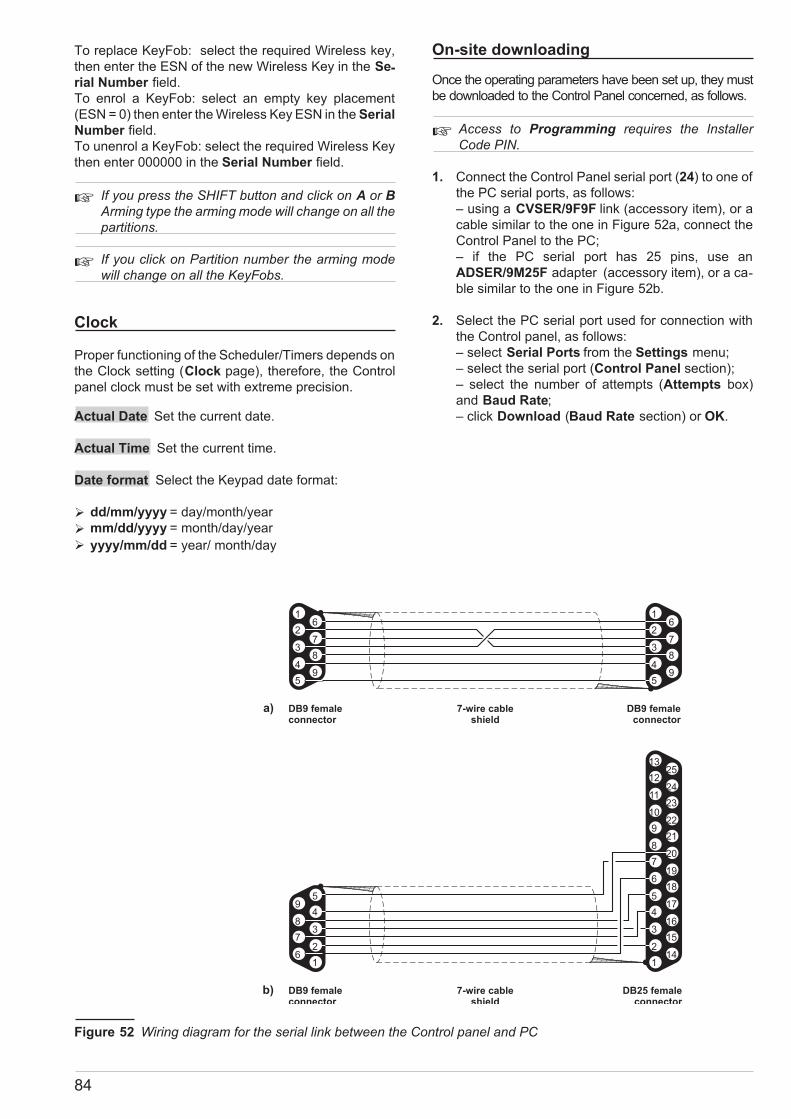
To replace KeyFob: select the required Wireless key,
then enter the ESN of the new Wireless Key in the Se-rial Number field.
To enrol a KeyFob: select an empty key placement
(ESN = 0) then enter the Wireless Key ESN in the Serial
Number field.
To unenrol a KeyFob: select the required Wireless Key
then enter 000000 in the Serial Number field.
� If you press the SHIFT button and click on A or B
Arming type the arming mode will change on all thepartitions.
� If you click on Partition number the arming modewill change on all the KeyFobs.
Clock
Proper functioning of the Scheduler/Timers depends on
the Clock setting (Clock page), therefore, the Control
panel clock must be set with extreme precision.
Actual Date Set the current date.
Actual Time Set the current time.
Date format Select the Keypad date format:
� dd/mm/yyyy = day/month/year
� mm/dd/yyyy = month/day/year
� yyyy/mm/dd = year/ month/day
On-site downloading
Once the operating parameters have been set up, they must
be downloaded to the Control Panel concerned, as follows.
� Access to Programming requires the InstallerCode PIN.
1. Connect the Control Panel serial port (24) to one of
the PC serial ports, as follows:
– using a CVSER/9F9F link (accessory item), or a
cable similar to the one in Figure 52a, connect the
Control Panel to the PC;
– if the PC serial port has 25 pins, use an
ADSER/9M25F adapter (accessory item), or a ca-ble similar to the one in Figure 52b.
2. Select the PC serial port used for connection with
the Control panel, as follows:
– select Serial Ports from the Settings menu;
– select the serial port (Control Panel section);
– select the number of attempts (Attempts box)
and Baud Rate;
– click Download (Baud Rate section) or OK.
84
5
4
6
5
4
3
2
1
9
18
8
19
17
16
15
14
7
20
21
22
23
24
25
6
3
7
2
8
9
10
11
12
13
1
DB9 femaleconnector
a)
b) 7-wire cableshield
DB25 femaleconnector
5 5
4 49 9
8 8
7 7
6 6
3 3
2 2
1 1
DB9 femaleconnector
7-wire cableshield
DB9 femaleconnector
Figure 52 Wiring diagram for the serial link between the Control panel and PC

3. Select the parameters to be downloaded, as fol-lows:
– select Parameters from the Settings menu;
– enter a valid Installer code in the Installer code
field;
–select the Control panel type from the Panel type
menu;
–select the relevant firmware release from the
Firmware Release menu;
– click OK.
4. To download a specific page: click the Download
button on the page concerned.
5. To Download several pages:
– select the required page from the Folders menu,
right click, select Tag (a � on the page Icon indi-cates that it will be downloaded);
– repeat the procedure for all the required Pages;
– right click again then select Download.
� To download a family of pages, select the root.
! If you send the User page with other pages, the
Control panel WILL STORE the Description, En-
abled Partitions, Associated Timers, User Menu
Access and Code type parameters, but WILL NOT
STORE the Available status, Active status, Duress
Code, Patrol Code and Father Code parameters.
� If changes to the Descriptions are not shown on theKeypads, use the Broadcast Keyp.command
from the INSTALLER MENU.
For example: – to download all the Configuration re-lated pages, select Configuration from the Folders
menu; to download All the Pages, select KYO 320 from
the Folders menu.
6. To view the parameters of the connected Control
Panel, work carefully through point 4. then select
Upload instead of Download.
Firmware Upgrade
Under "Programming Menu" in addition to Upload and
Download item there is Firmware Upgrade.
When a new Firmware is released, a file .hex will be
given to the installer. This file will run after selecting the
"Start" button (see Figure 53). In this fase if the system
goes in black-out or block, it is necessary to check on
"Restore Panel" and click on "Start". To restore the sys-
tem with the default setting call the Service).
Remote Downloading
You can download the programming data via telephone
line, using a B-Mod or B-Mod/RX modem, as follows.
� Telephone access requires entry of the Installer codePIN, and will ONLY be allowed when the Teleserviceoption has been Enabled by the User (refer “En-able/Disable Teleservice” in the USER’S MANUAL).
1. Using the serial cable (the same as used for On-site Down-loading),connect theModemtooneof thePCserialports.
2. Select the PC serial port for connection with the
Modem, as follows:
– select Serial Ports from the Settings menu;
– select the serial port (Modem section);
– select OK.
3. Select Connecting from the Modem menu: this com-mand will open the Connecting window ( Figure 53).
4. Program the following parameters:
– Telephone Number – enter the Control panel
telephone number;
– Disable Tone Check – Enable/Disable this op-tion as required.
If this option is Enabled, the Modem will not check
for the dialling tone before dialling;
– Double call – refer to the Teleservice page;
– Call back – refer to the Teleservice page;
– Installer Code – enter a valid Installer code PIN
(enabled for Downloading)
When the Connecting window opens, the above pa-rameters (except for Disable Tone Check) will have
the programmed settings.
KYO320 PROGRAMMING 85
Figure 53 Connecting Window Figure 54 Upgrade Firmware window

� The parameters in the Connecting window can bechanged temporarily without affecting the pro-grammed parameters of the open Customer.
5. Press Dial: the connection status will be shown in
the box at the bottom of the Connecting window
(refer to “Messages”). If the connection is com-pleted properly, the following message will be
shown:
KYO320 ACK
02.00
CONNECTION
6. Select OK: the Connecting window will close.
At this point, it will possible to download/upload
to/from the connected Control panel.
7. To program and view the parameters of the con-nected Control panel, work carefully through steps
4. and 5. in the “On-site Downloading” section.
8. Select On-hook from the Modem menu to end the
connection.
Messages The connection status will be shown in the
box at the bottom of the Connecting window, as follows.
MODEM v. x.xxThis is the release of the Modem that
is connected to the PC serial port
Modem not
recognized
The application cannot find the Bmod
on the specified serial port.
Check the cable and serial port
settings
Receiving...
The Modem/PC system is waiting for
an incoming call. This is the status
when the Connections window opens
RINGThe modem detects rings on the
telephone line
BUSY The dialled number is busy
BACKRING the dialled number is ringing
KYO320 ACKA KYO320 Control Panel has been
recognized
2.00This is the Firmware Release of the
Control panel
CONNECTIONThe Modem and Control Panel are
connected
ON HOOK The Modem has released the line
Installer Code
reading error
The Control panel cannot read the
PIN — probably due to a poor quality
signal on the telephone line
Lost
Connection
It is impossible to communicate with
the Control Panel — probably due to
a poor quality signal on the
telephone line
86

Check Panel
The Check option from the menu bar of
KYO320 downloading software application
provides two sub-options: Check Panel and
Check Configuration.
Check Panel This option will allow you to view the
real-time status of the Control panel (see Fig. 56).
Entry of a valid User code PIN will allow you to
control the Zones, Outputs and Partitions and view
the Timers and Trouble windows.
To operate on a specific Partition: click on the
Partition concerned then right-click to open a menu
(see Fig. 56) which will allow you to:
D: Disarm; A: Arm Away mode; S: Arm Stay
Mode; I: Instant (Arm Stay 0 Delay Mode) or Re-set the Partition concerned and Control panel.
To operate on a ALL Partitions: right-click on
the Partition section to open a menu which will al-low you to:
D: Disarm ALL Partitions; A: Arm ALL Partitions in Away
mode; S: Arm ALL Partitions in Stay mode; I: Arm ALL
Partitions in Instant mode (Stay 0 Delay) or Reset ALL
Partitions and Control panel.
To operate on a specific Zone:
right click on the Partition the
Zone belongs to, then right-click
to open a menu which will allow
you to: Bypass; Unbypass or
view the real-time analogue
value of the Zone. To control an
Output: right-click on the Output concerned to open a menu
which will allow you to turn the Output ON or OFF.
About the function buttons (un-der User PIN field)
Clicking on the first button
will open a menu which will
allow you to disable display of real-time status
data (enabled at default) regarding the Zones, Parti-tions, Trouble, Outputs and Timers.
Clicking on the second button will open
a menu with the following options: Show
violated zones only; Audible signalling
(Beep); Clear manually.
Clicking on the third button will allow you
to enable "Test" mode on ALL Zones.
Clicking on the fourth button will allow
you to disable "Test" mode on ALL
Zones.
Clicking on the fifth button will allow you
to Reset "Programming from PC" Trou-ble.
Clicking on the sixth button will close the
window.
Check Configuration This option will allow you to
view the status of the Control panel peripherals in either
Test mode or Graphic mode (see Fig.57).
Graphic mode: The real-time status of each peripheral
will be indicated by the colour of its icon, as follows:
� Green: the peripheral concerned is in the configura-
tion and operating properly.
� Red: the peripheral concerned is in the configuration
but is in Tamper status (e.g. Frontplate open).
� Yellow: the peripheral concerned is in the configura-tion but is missing.
� Orange: the peripheral concerned is in the configu-ration but has the same address as another periph-eral of the same type (Duplicated peripheral).
� White: the peripheral concerned is not included in
the configuration.
� In Test mode the real-time status of each peripher-als will be indicated by the colour of the virtual LEDlocated next to it.
KYO320 PROGRAMMING 87
Figure 55 Check panel Window
Figure 56 Check Configuration Window

88

APPENDIX
K3/VOX2 Voice Board
! Disconnect the Mains and battery power before
starting the installation procedure.
The K3/VOX2 Voice board records and plays Voice
messages. The recorded voice messages can be as-signed to the:
� Status enquiry
� Answer message
� Dialler messages
� Memo
� Continuous recording
� Features
� Messages stored on ChipCorder
� Manages up to 64 Voice messages with programma-
ble sound quality and duration — varying from 3
minutes 48 seconds of high sound quality to 8
minutes 44 seconds of low sound quality
� Speaker for Message playback
� Telephone-dialler
� Answerphone
� Telephone access
� Listen-in and remote 2way Speaker system
(Teleassistance)
� At default the Voice board will record messages, ifpower to the Voice board fails, the recorded mes-sages will be stored for at least 2 hours.
� Identification of Parts
No. DESCRIPTION
112 LED terminal : in the "remote Listen in" case, aLED with 470 Ohm resistor must be connectedbetween the LED terminal and the + terminal.
113 Main Unit Voice board connector114 Microphone115 Local Microphone Jumper (114):
// = Local Microphone enabled (at default)oo = Local Microphone disabled
116 Speaker Connector117 Terminal board (for Microphone board connec-
tion) (VOX-REM)
� Installation
Work carefully through the following steps (see Fig-
ure 57 and Figure 2 on page 11).
1. Insert the Speaker into one part of the plastic
holder.
2. Join the two parts then twist to lock in place.
3. Screw the Speaker onto the backplate.
4. Plug the Voice board into the connector 17, secure
it firmly in position by means of the screws.
5. Plug the Speaker into the connector 116 on the
Voice board.
6. Insert the jumper 112 (to store recorded messages
during blackout).
� Expanding Listen-in coverage
You can expand Listen-in coverage by connecting sev-eral Microphone-Speaker boards to the Voice board.
This is especially useful for large premises, or in places
where there is a high risk of sound muffling caused by
walls or heavy machinery, etc.
� In the text and diagrams in this section, the term “VoiceModule” refers to VOX-REM Microphone-Loudspeakerboard and the ALISON-DVP Keypad.
The VOX-REM Microphone-Speaker board can be
housed in custom made accessory boxes with wire en-try knockouts (order code: MINI-BOX). The MINI-BOX
can be wall mounted, or flush mounted to 503 outlet
boxes or similar. The installation instructions can be
found in the MINI-BOX package.
KYO320 APPENDIX 89
LE
D
MIC + SP
K+
SP
K-
EXT.SP
EN.MIC
113 114 115 116 117
112
Figure 57 Voice board components
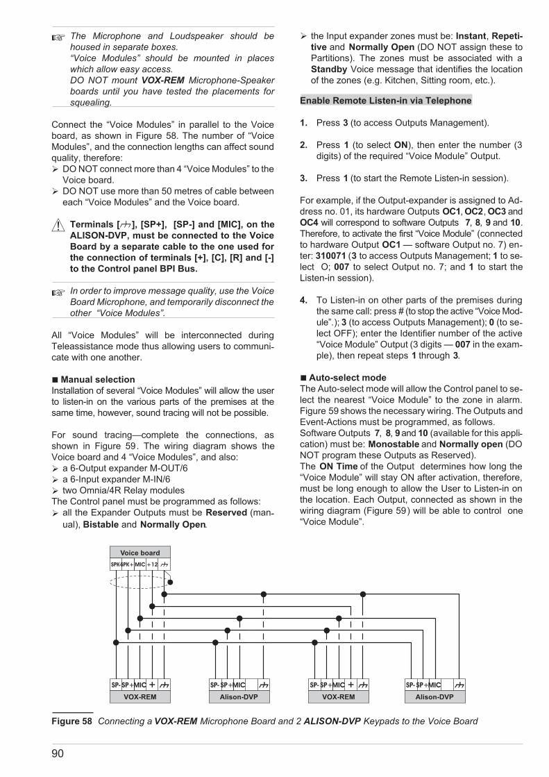
� The Microphone and Loudspeaker should behoused in separate boxes.“Voice Modules” should be mounted in placeswhich allow easy access.DO NOT mount VOX-REM Microphone-Speakerboards until you have tested the placements forsquealing.
Connect the “Voice Modules” in parallel to the Voice
board, as shown in Figure 58. The number of “Voice
Modules”, and the connection lengths can affect sound
quality, therefore:
� DO NOT connect more than 4 “Voice Modules” to the
Voice board.
� DO NOT use more than 50 metres of cable between
each “Voice Modules” and the Voice board.
! Terminals [M], [SP+], [SP-] and [MIC], on the
ALISON-DVP, must be connected to the Voice
Board by a separate cable to the one used for
the connection of terminals [+], [C], [R] and [-]
to the Control panel BPI Bus.
� In order to improve message quality, use the VoiceBoard Microphone, and temporarily disconnect theother “Voice Modules”.
All “Voice Modules” will be interconnected during
Teleassistance mode thus allowing users to communi-cate with one another.
�Manual selection
Installation of several “Voice Modules” will allow the user
to listen-in on the various parts of the premises at the
same time, however, sound tracing will not be possible.
For sound tracing—complete the connections, as
shown in Figure 59. The wiring diagram shows the
Voice board and 4 “Voice Modules”, and also:
� a 6-Output expander M-OUT/6
� a 6-Input expander M-IN/6
� two Omnia/4R Relay modules
The Control panel must be programmed as follows:
� all the Expander Outputs must be Reserved (man-
ual), Bistable and Normally Open.
� the Input expander zones must be: Instant, Repeti-
tive and Normally Open (DO NOT assign these to
Partitions). The zones must be associated with a
Standby Voice message that identifies the location
of the zones (e.g. Kitchen, Sitting room, etc.).
Enable Remote Listen-in via Telephone
1. Press 3 (to access Outputs Management).
2. Press 1 (to select ON), then enter the number (3
digits) of the required “Voice Module” Output.
3. Press 1 (to start the Remote Listen-in session).
For example, if the Output-expander is assigned to Ad-dress no. 01, its hardware Outputs OC1, OC2, OC3 and
OC4 will correspond to software Outputs 7, 8, 9 and 10.
Therefore, to activate the first “Voice Module” (connected
to hardware Output OC1 — software Output no. 7) en-ter: 310071 (3 to access Outputs Management; 1 to se-lect O; 007 to select Output no. 7; and 1 to start the
Listen-in session).
4. To Listen-in on other parts of the premises during
the same call: press # (to stop the active “Voice Mod-ule”.); 3 (to access Outputs Management); 0 (to se-lect OFF); enter the Identifier number of the active
“Voice Module” Output (3 digits — 007 in the exam-ple), then repeat steps 1 through 3.
� Auto-select mode
The Auto-select mode will allow the Control panel to se-lect the nearest “Voice Module” to the zone in alarm.
Figure 59 shows the necessary wiring. The Outputs and
Event-Actions must be programmed, as follows.
Software Outputs 7, 8, 9and 10 (available for this appli-cation) must be: Monostable and Normally open (DO
NOT program these Outputs as Reserved).
The ON Time of the Output determines how long the
“Voice Module” will stay ON after activation, therefore,
must be long enough to allow the User to Listen-in on
the location. Each Output, connected as shown in the
wiring diagram (Figure 59) will be able to control one
“Voice Module”.
90
SPK+
SP+ SP+ SP+ SP+
SPK-
SP- SP- SP- SP-
MIC
MIC MIC MIC MIC
Voice board
VOX-REM Alison-DVP VOX-REM Alison-DVP
+12
Figure 58 Connecting a VOX-REM Microphone Board and 2 ALISON-DVP Keypads to the Voice Board

Use the Partition and/or Control panel Events in the
Event-Actions page to activate the Dialler and Tele-phone Communicator Outputs. In this way, the zone
events will be available for “Voice Module” manage-ment. Program the zone events (relevant to the loca-tion concerned) to activate the Output that controls the
respective “Voice Module”. Repeat this procedure for
the other Outputs, as required.
Upgrade FirmwareAuto-select mode will allow the User
(during a dialler call) to activate Remote listen-in on the
location that generated the Alarm.
� Manual and Auto-select mode
Manual and Auto-select Listen-in can be integrated.
This will allow the User to select (manually) specific lo-cations during standby status.
Use 4 Outputs for Manual-select Listen-in mode, and 4
Outputs for Auto-select listen-in mode.
The Outputs must be connected in two’s — one Manual
and one Auto, as shown in Figure 59.
To ensure proper functioning of Auto-select mode, the man-ually controlled Outputs must be in standby status. There-fore, the Outputs must always be restored to Standby when
a manually controlled listen-in session ends.
K3/PRT2 Printer Interface
! Disconnect the Mains and battery power before
starting the installation procedure.
The optional K3/PRT2 Printer Interface will allow you to
connect the Control panel to a parallel printer for:
— Real-time printout of events (refer to “Accessories”
under “Configuration” in the Programming” section);
— Entire Log printout (refer to “Print Log” under “Key-pad Codes – User” in the Programming” section and/or
“Event Log” under “Operating your system from a Key-pad” in the USER MANUAL);
— Specific events printout (refer to “ Log — Events
Setup” under “Programming”).
� Identification of Parts
The following Table describes the parts illustrated in
Figure 60. The numbers in boldface in this section, refer
to parts in Figure 60 (unless otherwise specified).
No. DESCRIPTION
118 Interface connector119 Printer connector
� Connecting the Printer
If you prefer to chase the lead, use a plug-free cable (re-fer to Table 12 for the wiring specifications and see also
Figure 61). Moulded plug leads (usually supplied with
the printer) cannot be chased.
� Installation instructions
Work carefully through the following steps (see Fig-ure 60 and Figure 2 on page 11).
1. Lay the cable between the printer and the Control
panel.
KYO320 APPENDIX 91
SPK+
SP+ SP+ SP+ SP+
SPK-RL1 RL1
SP- SP- SP- SP-
MICRL2
L2 L4L3L1
RL2RL3 RL3RL2 RL2
MIC MIC MIC MIC
Voice board
Output exp. 01 Input exp. 01
Omnia/4R Omnia/4R
1 Voice modulest
2 Voice modulend
3 Voice modulerd
4 Voice moduleth
+12
* * * *
Connect ONLY the [+] terminals of the
board to the terminal [+12] of
the Voice Board. The [+] terminals of
Keypads must be connected
to the [+] terminal of the Control panel.
VOX-REM
Alison-DVP
*
Figure 59 Wiring for Manual-select Listen-in mode

2. Plug the Printer interface into the connector 15 on
the Control panel PCB then, using the screws, se-cure it in place.
3. Connect the Printer lead to the connector 119 on
the Printer Interface.
VectorRX, VRX32-433 and VectorRX-8Receiver
The VectorRX, VRX32-433 Receiver (accessory item) willallow your system to manage up to 32 Wireless detectors(PIRs, Magnetic Contacts, Smoke detectors), and up to 16Wireless keys (KeyFobs). VectorRX-8 Receiver man-ages up to 8 Wireless detectors (PIRs, Magnetic Con-tacts, Smoke detectors), and up to 8 Wireless keys(KeyFobs). Please read this section to get an overall
view of the steps involved in installing the VectorRX Re-ceiver.
The term “Receiver or VectorRX Receiver” has been
used in the parts where the functions and operating
modes are common to all Receivers. However, in parts
where the functions and operating modes differ, the re-spective Receiver has been specified.
� Identification of Parts
The following Table describes the components of the
Receiver (see Figure 62-64-65). The numbers in bold-face in this section, refer to the descriptions in the Table
and Figure.
No. DESCRIPTION
120 Spring catch slots (2)121 Anchor screw locations (3 x ø 4.6 mm)122 Antennas (2)123 Microprocessors (2)124 Seize microswitch125 Tamper button126 Screws (2)127 Wire entry (10 x 6.4 mm)128 Spring Catch129 Terminal board
129a PCB clip
� Choosing a Mounting Location
� Mount the Receiver and Wireless Devices after theplacement tests.
Choose a place that is:
� Dry
� Central to the proposed placement of all Wireless
Devices
� As close to the ceiling as possible
� Far from sources of interference such as: electrical
noise (computers, televisions, electric motors in ap-pliances, and heating and air-conditioning units),
and large metal objects (heating ducts and plumb-ing) which may shield the antennas.
Ensure that no electrical wires run over the Receiver
antennas. When mounting in a basement, place the
module as high and as close to the underside of the first
floor as possible. The range of the Receiver will be re-duced if the unit is mounted below ground level.
92
Interface connector: DB25 connector, male
1 2 3 4 5 6 7 8 9 10 11 12 13 14 15 16 17 19
18 wire cable + shield: the shield must be soldered to the metal casing of both connectors
1 2 3 4 5 6 7 8 9 10 11 12 13 14 32 31 36 15÷17/19÷30
Printer side: Centronics connector, 36 pin, male
Table 12 Wiring diagram of the cable between the parallel printer and the Printer Interface
118 119
Figure 60 Printer Interface components
18
20
21
22
23
24
25
Printer side:Centronics connector, male:pins from 15 to 17 and 19 through 30must be connected togetherand to pin 19 of the DB25 connector
18 wire shielded cable:
the shield must be solderedto the metallic casingof both connectors
(max. length 10 m)
Interface side:DB25
connectormale
13
12
11
10
9
8
7
6
5
4
3
2
114
15
16
17
19
1
2
3
4
5
6
7
8
9
10
11
12
13
14
16
17
15
1836
35
34
33
32
31
30
29
28
27
26
25
24
23
22
21
20
19
Figure 61 Wiring diagram of parallel printer cable
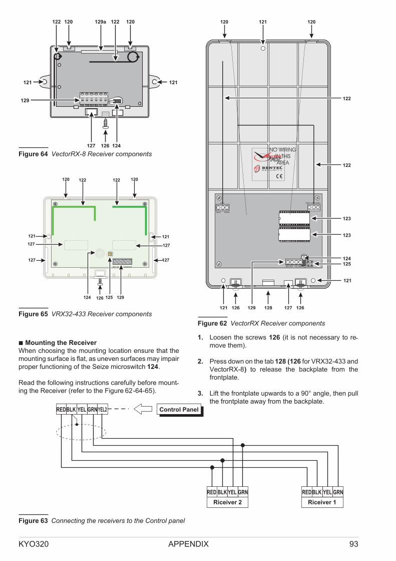
� Mounting the Receiver
When choosing the mounting location ensure that the
mounting surface is flat, as uneven surfaces may impair
proper functioning of the Seize microswitch 124.
Read the following instructions carefully before mount-ing the Receiver (refer to the Figure 62-64-65).
1. Loosen the screws 126 (it is not necessary to re-move them).
2. Press down on the tab 128 (126 for VRX32-433 and
VectorRX-8) to release the backplate from the
frontplate.
3. Lift the frontplate upwards to a 90° angle, then pull
the frontplate away from the backplate.
KYO320 APPENDIX 93
NO WIRING
IN THIS
AREA
RED BLK YEL GRN
ATN1GND11 GND1ATN1
GND22GND2
®
121
125124
123
123
122
129121
120 120121
126127128126
122
Figure 62 VectorRX Receiver components
Riceiver 1
GRNRED Control PanelYELBLK
GRNRED YELBLK
YEL2
Riceiver 2
GRNRED YELBLK
Figure 63 Connecting the receivers to the Control panel
126
120 120129a122 122
129
127
121
124
121
Figure 64 VectorRX-8 Receiver components
RED BLK YEL GRNGND
120
121
120
126
121
127 127
129124 125
122122
127 127
Figure 65 VRX32-433 Receiver components
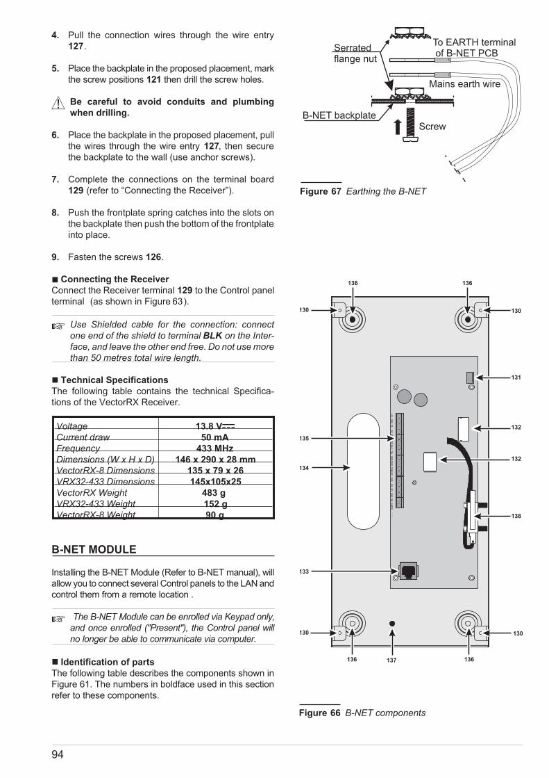
4. Pull the connection wires through the wire entry
127.
5. Place the backplate in the proposed placement, mark
the screw positions 121 then drill the screw holes.
! Be careful to avoid conduits and plumbing
when drilling.
6. Place the backplate in the proposed placement, pull
the wires through the wire entry 127, then secure
the backplate to the wall (use anchor screws).
7. Complete the connections on the terminal board
129 (refer to “Connecting the Receiver”).
8. Push the frontplate spring catches into the slots on
the backplate then push the bottom of the frontplate
into place.
9. Fasten the screws 126.
� Connecting the Receiver
Connect the Receiver terminal 129 to the Control panel
terminal (as shown in Figure 63).
� Use Shielded cable for the connection: connectone end of the shield to terminal BLK on the Inter-face, and leave the other end free. Do not use morethan 50 metres total wire length.
� Technical Specifications
The following table contains the technical Specifica-tions of the VectorRX Receiver.
Voltage 13.8 V_
Current draw 50 mA
Frequency 433 MHz
Dimensions (W x H x D) 146 x 290 x 28 mm
VectorRX-8 Dimensions 135 x 79 x 26
VRX32-433 Dimensions 145x105x25
VectorRX WeightVRX32-433 Weight
483 g
152 g
VectorRX-8 Weight 90 g
B-NET MODULE
Installing the B-NET Module (Refer to B-NET manual), will
allow you to connect several Control panels to the LAN and
control them from a remote location .
� The B-NET Module can be enrolled via Keypad only,and once enrolled ("Present"), the Control panel willno longer be able to communicate via computer.
� Identification of parts
The following table describes the components shown in
Figure 61. The numbers in boldface used in this section
refer to these components.
94
T1
R1
+1
2G
ND
TX
RX
GN
DR
ED
BL
KY
EL
GR
NP
GM
1P
GM
2IN
1G
ND
IN2
IN3
GN
DIN
4E
AR
TH
130
130130
130
135
133
131
132
132
134
136 136
136136 137
138
Figure 66 B-NET components
B-NET backplate
Serratedflange nut
To EARTH terminalof B-NET PCB
Screw
Mains earth wire
Figure 67 Earthing the B-NET

No. DESCRIPTION
130 Backplate screw locations (4)131 Connector for the Control panel link.132 Microprocessors (2)133 LAN link134 Cable entry135
136
137
138
Terminal boardAnchor screw holes (4)Earth Wire entry (see Fig.64)Tamper microswitch (Accessory item)
� Mounting the B-NET Module
The B-NET Module should be mounted on a flat wall di-rectly below the Control panel. Do not mount the
B-NET Module on an uneven surface as this may affect
proper closure of the box. Work through the following
instructions carefully (see Figure 63).
1. Remove the screws 130 and frontplate.
2. Drill the holes 136 for the B-NET Module anchor
screws.
3. Pull the connection wires through the cable entry
134 then attach the backbox to the wall.
4. Complete the connections — DO NOT connect the
Mains until all other wiring has been completed.
5. Using the B-NET link (inside the package), connect
the B-NET Module (via connector 131) to the serial
port on the mother board, then connect the B-NET
Module (via connector 133) to the LAN.
� If required, connect the Tamper microswitch to theControl panel tamper line.
� Technical Specifications
The following table contains the technical specifications
of the B-NET Module.
Voltage 13.8 V_
Current draw 250 mA
Dimensions (W x H x D) 150 x 339 x 108 mm
Weight 1475 g
Reset default
To reset the factory default programming:
1. Remove all power from the Control panel (Mains
and battery).
2. Remove the jumper 21 (M).
3. Wait at least 20 seconds.
4. Replace the jumper 21 (M).
5. Restore power to the Control panel (refer to “Con-necting the Power Supply” under “INSTALLING THE
KYO320”).
! Jumper 21 (M) must be disconnected for at
least 20 seconds in order to ensure full reset of
the factory default programming, and to avoid
problems that may occur when the power sup-
ply is restored.
Installer code locked If the Lock Installer code op-tion is enabled, the Installer PIN will not be able to reset
to factory default (refer to Lock Installer code in the Op-tions section).
Reporting Formats
This paragraph describes the structures of the main
reporting formats supported by the system.
� TELIM
The TELIM protocol transmits as follows:
� User Code (4 digits — 0 through 9);
� Event Code: 41 in the event of Alarm or Tamper on
the first 16 zones of the Control panel, 0 in all other
cases;
� 2 byte (16 bit) representing the status of the first 16
zones — 0 Standby; 1 = Alarm or Tamper.
� Contact ID
Contact ID transmits as follows:
� User Code (4 hexadecimal digits — 0 through F );
� Qualifier: 1 = new event or Disarming operation; 3
event restore event or Arming operation
� Class Code (CL. column): identifies the type of
event (Alarm, Trouble, Fire, etc.);
� Event Code (CODE column): identifies the event
(Event Codes can be changed, refer to “Actions” un-
KYO320 APPENDIX 95
KYO320 CONTROL PANEL
BUS BPI
B-NET MODULE
DETECTORS
POWER SUPPLY
B-NET
®®
SERVER
LAN NET
12
34
12
34
INPUTEXPANDER
OUTPUTEXPANDER
BUS BPI
2abc
A BC
D
ESC
1 3def
5jkl
4ghi
6mno
8tuv7 pqrs 9wxyz
0 OFF#ON
PIN
PIN
PIN
PIN
PIN
PIN
Inserimento Aree
Inserimento A, B, C o D
Disinserimento Aree
Reset Memorie
Blocco Allarme�
Cancella Telefonate
Arming Partitions
Arming Type A, B, C or D
Disarming Partitions
Reset Alarms
Stop Alarms�
Clear Calls
AreeInserite
SabotaggioCentrale
ScomparsaPeriferica
ChiaveFalsa
SabotaggioPeriferica
Sabotaggio
GuastoAllarme
Messaggio
Teleassist.Abilitata
Rispondit.Abilitato
Telefonatain corso
ArmedPartitions
Alarm
Message
Warning
PanelTamper
TamperPeripheralTamper
FalseKe /CardyMissingPeri heralp
TeleserviceEnabled
AnswerPhone ONCall inprogress
ET
IDF
BL
1A
LS
-S0
.02
90
90
3D
10
oor
12
34
56
7
8
http:\\www.bentelsecurity.com
n.Des.
O
A B C D
o
EE
EDE
ECE
WINTEK WM-C1602N-2GLYc
A
K
PICVUE 160206QGL01
K
A
KEYPAD
READER and DIGITAL KEY
Figure 68 Example of a B-NET configuration

der “Digital Communicator” in the “PROGRAMMING”
section);
� Group Number (GROUP column), where possible,
identifies the Partition of the “object” which gener-
ated the event;
� Zone Number (ZONE column), where possible,
identifies the “object” (Zone, Code, Key, etc.) which
generated the event.
� SIA/SIA over B-NET
SIA/SIA over B-NET is a FSK (Frequency Shift Keying) for-mat, that transmits alternatively in two slightly different fre-quencies. The frequency shift is usually 170 Hertz, and the
two frequencies are associated with 0 and 1 of the binary
digit which transmits the following data:� User Code (4 digits — 0 through 9)
� Function Code (1 digit; N=new event, O=restore event)
� Date (month-day-year)
� Time (hour-minutes-seconds)
� Event Type (refer to the TYPE column in Table 13)
� Event Agent (refer to the 1st and 2nd columns in Ta-ble 13).
dbManager
DbManager (in Bentel security Suite) is an application
developed to copy safely customer’s data from a source
to a destination. For example, data can be copied on a
USB Flash Disk and can be used on a laptop. Besides
the DbManager can recover corrupted database data.
DbManager main window contains File, Acces Levels,
Language and Help menus, all described in the follow-ing paragraphs.
File Menu
Data transfer : Select Data transfer to copy cus-tomer’s data (see par. “Data transfer”)
Tools: Select Tools to access data recover utilities.
Exit: Select Exit to terminate the pro-gram.
� Data Transfer
Data Transfer from the File menu opens
the Data Transfer window described be-low (see also figure?).
Origin Select the disk and folder which
contains the customer accounts con-cerned.
� The Bentel security Suite applicationwill save customer account data tothe \DATA installation folder of thesuite (Bentel).
Customers Select the customer ac-
counts concerned from the Customer ac-
count list. To select/deselect ALL customer accounts
click on Selection.
Destination Select the destination disk and folder.
� The customer accounts must be saved to the\DATA installaton folder of the BSS Software suite(Bentel).
Data to transfer Select the data to export.
Show warnings Click on Show warnings if you want
information regarding the risk of exporting customer ac-counts with duplicated Codes or Names from the Ori-gin folder to the Destination folder.
In the event of a duplicated Name but different Code a win-dow as per figure ?a will open with the following options.
� Keep - the data of the customer account from the Origin
folder will overwrite the data of the customer account
with the duplicated Name in the Destination folder.
� Create (at default) - the data will be saved as a new
customer account with the same Name but different
Code as the customer account in the Origin folder.
� Do Not export - the data will not be saved.
96
Figure 69 DBmanager main window
Figure 70 Data transfer window

In the event of a duplicated Code but different Name a win-dow as per figure?b will open with the following options.
� Keep - the data of the customer account from the Origin
folder will overwrite the data of the customer account
with the duplicated Code in the Destination folder.
� Create (at default) - the data will be saved as a new
customer account with the same Name but different
Code as the customer account in the Origin folder.
� Do Not export - the data will not be saved.
� If you disable the Show Warning option, the appli-cation will enable the Create option automatically.
Panel types Check in this box panel types involved in
the data transfer. The Customers window will show all
the customers using the selected panel type.
Print Select Print to print down a list showing all cus-tomers shown in the Customers window.
� Tools
Tools command opens Tools window, as shown below.
Data path Select the source drive and folder contain-ing the database to be restructured/reindexed
Update structure Use Update structure to regener-ate the internal phisical structure of the database. If dur-ing normal use, one of BSS softwares shows a “File not
found” or “Table does not exist” error, update your data-base’s structure.
Reindex Use Reindex to generate all the database in-dexes. If during normal use one of BSS softwares
shows a “Corrupt table index” or “Index for field does
not exist” error, perform a reindex on your database.
Close Closes the Tool window.
� Almost all database errors are caused by a phisicaldamage of its files. Even if Bentel utilities can re-cover corrupted database files, if you’re having fre-quent database errors, there could be somehardware problem on your PC
Access Levels Menu
KYO320 APPENDIX 97
EVENT CONTACT ID SIA
CL. CODE GROUP ZONE TYPE 1st 2nd
Alarm on zone 1 30 00 zone no. BA/BR 0000 zone no.
Tamper on zone 1 37 00 zone no. TA/TR 0000 zone no.
Fire alarm on partition 1 10 part. no. 000 FA/FR part. no. 000
24h alarm on partition 1 33 part. no. 000 BA/BR part. no. 000
Burglar alarm on partition 1 30 part. no. 000 BA/BR part. no. 000
Generic alarm on partition 1 30 part. no. 000 BA/BR part. no. 000
Tamper alarm on partition 1 37 part. no. 000 TA/TR part. no. 000
Generic+Tamper alarm on partition 1 37 part. no. 000 TA/TR part. no. 000
Away alarm on partition 1 30 part. no. 000 BA/BR part. no. 000
Stay alarm on partition 1 30 part. no. 000 BA/BR part. no. 000
Fire alarm on panel 1 10 00 000 FA/FR 0000 000
24h alarm on panel 1 33 00 000 BA/BR 0000 000
Burglar alarm on panel 1 30 00 000 BA/BR 0000 000
Generic alarm on panel 1 30 00 000 BA/BR 0000 000
Tamper alarm on panel 1 37 00 000 TA/TR 0000 000
Generic+Tamper alarm on panel 1 37 00 000 TA/TR 0000 000
Tamper on Main unit 1 37 00 000 TA/TR 0000 000
Stop-alarms jumper 3 00 00 000 RO/RC 0000 000
Balanced tamper 1 37 00 000 TA/TR 0000 000
Tamper on supervised output 3 24 00 000 YA/YH 0000 000
Tamper BPI readers 3 41 00 000 ET/ER 0000 000
Tamper BPI input expanders 3 41 00 000 ET/ER 0000 000
Tamper on keypads 3 41 00 000 ET/ER 0000 000
Tamper output expanders 3 41 00 000 ET/ER 0000 000
Tamper power stations 3 41 00 000 ET/ER 0000 000
Tamper wireless device 3 41 00 000 ET/ER 0000 000
Warning readers 3 33 00 000 ET/ER 0000 000
Warning BPI input expander 3 33 00 000 ET/ER 0000 000
Warning keypads 3 33 00 000 ET/ER 0000 000
Warning output expanders 3 33 00 000 ET/ER 0000 000
Table 13 Structure of the main Reporting formats supported by the System (continued ...)

Access Levels menu provides the possibility to man-age users data for all Bentel Security Suite softwares.
Users List Shows the users list wondow. If you want to
delete or modify a user, username and password will be
requested.
98
EVENT CONTACT ID SIA
CL. CODE GROUP ZONE TYPE 1st 2nd
Warning power stations 3 33 00 000 ET/ER 0000 000
Warning wireless device 3 33 00 000 ET/ER 0000 000
False key 4 21 00 000 DD/DR 0000 000
Warning fuse +F 3 00 00 000 YP/YQ 0000 000
Warning fuse +F1 3 00 00 000 YP/YQ 0000 000
Warning fuse +B1 3 00 00 000 YP/YQ 0000 000
Warning fuse +B2 3 00 00 000 YP/YQ 0000 000
Warning fuse +B3 3 00 00 000 YP/YQ 0000 000
Warning fuse +B4 3 00 00 000 YP/YQ 0000 000
Warning fuse +B5 3 00 00 000 YP/YQ 0000 000
Warning fuse BPI1 3 00 00 000 YP/YQ 0000 000
Warning fuse BPI2 3 00 00 000 YP/YQ 0000 000
Warning fuse KEYBUS 3 00 00 000 YP/YQ 0000 000
Warning mains failure 3 01 00 000 AT/AR 0000 000
Warning low battery 3 02 00 000 YT/YR 0000 000
Warning power trouble 3 00 00 000 YM/YR 0000 000
Warning mains failure on Power station 3 01 00 000 AT/AR 0000 000
Warning low battery on Power station 3 02 00 000 YT/YR 0000 000
Warning power trouble on Power station 3 03 00 000 YM/YR 0000 000
Battery not connected on Power station 3 00 00 000 YP/YQ 0000 000
Battery charger trouble on Power station 3 00 00 000 YP/YQ 0000 000
Switching not connected on Power station 3 00 00 000 YP/YQ 0000 000
Short circuit output ½/3 on Power station 3 00 00 000 YP/YQ 0000 000
Battery low memory 3 07 00 000 YT/YR 0000 000
Warning low battery on wireless device 3 38 00 000 XT/XR 0000 000
Memory tamper BPI device 3 41 00 000 ET/ER 0000 000
Memory balanced tamper 1 37 00 000 TA/TR 0000 000
Memory tamper on main unit 1 37 00 000 TA/TR 0000 000
Memory false key 4 21 00 000 DD/DR 0000 000
Memory tamper supervised output 3 21 00 000 YA/YR 0000 000
Lost wireless zone 3 33 00 000 ET/ER 0000 000
Warning generic 3 00 00 000 BT/BJ 0000 000
Installer maintenance 6 00 00 000 QA/QH 0000 000
Central station maintenance 6 00 00 000 QA/QH 0000 000
Standard time/Summer time changed 6 25 00 000 JD/UX 0000 000
Not Ready-to-arm partition 3 00 part. no. 000 NF/NF part. no. 000
Extended not Ready-to-Arm partition 3 00 part. no. 000 NF/NF part. no. 000
Partial arming partition 4 41 part. no.11
NL/OP part. no. 000
Global arming partition 4 00 part. no.16
CL/OP part. no. 000
Disarming partition 4 00 part. no. 16 OP/CL part. no. 000
Exit time on partition 6 00 part. no. 000 UX/UX part. no. 000
Entry time on partition 6 00 part. no. 000 UX/UX part. no. 000
Autoarming warning partition 6 00 part. no. 000 UX/UX part. no. 000
Memory alarm on partition 1 30 part. no. 000 BA/BR part. no. 000
Memory tamper on partition 1 37 part. no. 000 TA/TR part. no. 000
Valid key 4 22 00 key no. JP/UX 0000 key no.
Key present on reader 4 22 00 reader no. JP/UX 0000 reader no.
Table 13 Structure of the main Reporting formats supported by the System

New User Inserts a new user in the database. Select
name and password, and then choose user’s rights.
Language menu shows the Language selection
window. Choose a new language and click OK.
Help Menu
Help shows this file for a fast reference.
� Copying Customer accounts
To copy customer accounts
1. Select Export data from the File menu.
2. Select the disk and folder of the customer accounts
concerned from the Origin box.
3. Select the required customer accounts from the Cus-tomers box.
KYO320 APPENDIX 99
EVENT CONTACT ID SIA
CL. CODE GROUP ZONE TYPE 1st 2nd
Valid key on partition4 22 00
partition
no.JP/UX 0000
partition
no.
Alarm stop on partition 6 00 part. no. 000 BC/UX part. no. 000
Alarm stop on panel 6 00 00 000 BC/UX 0000 000
Bypass zone 5 70 00 zone no. BB/BU 0000 zone no.
Telephone line trouble 3 51 00 000 LT/LR 0000 000
Error printer 3 36 00 000 VT/VR 0000 000
Call queue full 6 24 00 000 JL/UX 0000 000
Timer 6 00 00 000 UX/UX 0000 000
Real time of zone 6 00 00 zone no. UA/UH 0000 zone no.
Test 6 02 00 000 RP/UX 0000 000
Reset on partition 6 00 part. no. 000 BC/UX part. no. 000
Reset on panel 6 00 00 000 BC/UX 0000 000
Super key 6 00 00 000 UX/UX 0000 000
Key F on KeyFob 6 00 00 000 UX/UX 0000 000
Key A on KeyFob 6 00 00 000 UX/UX 0000 000
Key P on KeyFob 6 00 00 000 UX/UX 0000 000
Chime on partition 6 00 part. no. 000 UX/UX part. no. 000
Negligence on partition 4 04 part. no. 000 CD/UX part. no. 000
Delinquency on partition 6 00 part. no. 000 BT/BU part. no. 000
Block keypad 4 21 00 000 JA/UX 0000 000
Recognized user code 4 22 00 code no. JP/UX 0000 code no.
Recognized user code on Keypad 4 22 00 keypadno. JP/UX 0000 keypadno.
Recognized user code on Partition4 22 00
partition
no.JP/UX 0000
partition
no.
Invalid code 4 21 00 000 DD/DR 0000 000
Recognized installer code 6 27 00 000 LB/LX 0000 000
Second dialler on 3 50 00 000 UX/UX 0000 000
Kissoff recognized 3 50 00 000 UX/UX 0000 000
Start telephone call 3 50 00 000 UX/UX 0000 000
Teleservice requested 6 01 00 000 UX/UX 0000 000
Start Teleservice 6 01 00 000 RB/RS 0000 000
Dialler action OK 3 50 00 000 UX/UX 0000 000
Action on digital communicator OK 3 50 00 000 UX/UX 0000 000
Digital communicator action OK 3 50 00 000 UX/UX 0000 000
Teleservice action OK 3 50 00 000 UX/UX 0000 000
Dialler action failed 3 54 00 000 UX/UX 0000 000
Action on digital communicator failed 3 54 00 000 UX/UX 0000 000
Digital communicator action failed 3 54 00 000 UX/UX 0000 000
Teleservice action failed 3 54 00 000 UX/UX 0000 000
User event 6 00 00 000 UX/UX 0000 000
Table 13 Structure of the main Reporting formats supported by the System

4. Select the destination disk and folder from the Desti-nation box.
5. Select Log and/or Show warnings.
6. Select Execute - if there are no customer accounts in the
Destination folder, the following warning will be shown.
7. Select Yes to copy
Main Differences between KYO300-100 (rev. 1.30)
and new KYO320 control panel
� The Control panel release can be read on the Mi-croprocessor (see Part no. 39 on page 11), or onany of the system Keypads, by means of the Re-lease option from the INSTALLER MENU.
Serial Port The Baud Rate can be increased up to
115.200 bps.
LCD string On the first start you can select four lan-guages by LCD keypad or PC.
Vibration and Roller Blind Zones Direct connecting
to 8 zones on board of Roller Blind or Vibration Detector
with three balancing possibility: NC (Normally Closed),
Balanced 1K and Customized.
Wireless Zones Up to 64 Zones with two Vector-RX,
up to 16 Zones with two Vector/RX-8.
KeyFobs From 16 up to 32 KeyFobs, 1 or 2 Vector-RX
and VRX32-433. From 8 up to 16, 1 or 2 VectorRX-8
receivers. The KeyFobs are enrolled one by one with ,
A, B or Away arming and SuperKey.
High-Low Volume On the software Telephone page
there is the possibility to choose High or Low volume
(In Teleassistance case).
Digital communicator New Action pages: now it is
possible to select up to 8 different numbers for the same
action, even if different protocols are used.
Contact ID and SIA event code The Contact ID and
SIA event codes are programmable for every Control
Panel event.
K3/VOX2 Voice board It is no more necessary to set
the Time of the programming messages. In recording
fase the time is automatically set. Message No. 63 can
be used for the Memo function only and Message No.
64 for the Continuous Recording function only.
Keypad manage Unlike KYO300, the new KYO320 con-trol panel manages all Bentel LCD keypad (Alison-S,
Alison-DVP, MIA-S and MIA-D( see note page 7).
KYO320 Control panel complies with RoHs.
ISTISBLEKYO320 0.0 250107 V10
A) B)
Figure 71 Choose action Windows