Embed Size (px)
DESCRIPTION
Bentel Fire Manual
Citation preview
®
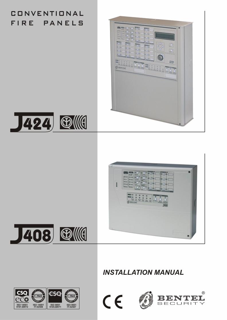
INSTALLATION MANUAL
CONVENTIONALF I R E PA N E L S
424
408
ISO 140019191.BNT2
ISO 14001IT-52588
ISO 90019105.BNT1
ISO 9001IT-52587

This Control panel can be programmed using the respective Software J400 release 1.1 or higher.
BENTEL SECURITYsrl shall not assume the responsibility for damage arising from improper application or use.
This Control panel has been designed and manufactured to the highest standards of quality and performance.
Installation of this Control panel must be carried out strictly in accordance with the instructions described in this manual, andin compliance with the local laws and bylaws in force
The J424 and J408 Control panels comply with the essential requirements of standards EN54-2; EN54-4; EN12094-1.
EN12094-1 certification shall be deemed void if the J400-EXT Extinguishment Module is not installed in the Control panel.
The J424 and J408 Control panels, all their accessories and functions, unless otherwise specified (see notes marked A), areIMQ Security Systems Grade II Listed.
BENTEL SECURITY srl reserves the right to change the technical specifications of these products without prior notice.
EN12094-1
Electrical automatic control and delay device
Environmental class A
Protection level IP30
Flooding zones 1 to 2
CO2, inert gas, halogenate hydrocarbon
Expected Options:
– Delay of extinguishing signal
– Monitoring of status of components
– Emergency hold device
– Control of flooding time
Response delay activated condition: maximum 3 s
Response delay triggering of outputs: maximum 1 s
1328-CPD-0067
1328-CPD-0068
07
(J424)
(J408-2/J408-4/J408-8)
1328
CONTENS
INTRODUCTION 5The J424 and J408 Control panels 5
Accessory Items 5Description 5
Inputs 5Outputs 6Operating features 6Interface 7Extinguishment Module 8Access to Signalling and Commands 8Power Supply 8
IDENTIFICATION OF PARTS 9The Status LEDs 9Description of Parts 14Description of the Control keys 20
INSTALLING THE CONTROL PANEL 21Installing accessory boards 21
Installing Extinguishment Modules 21Installing Expander Module Kit (for J424 ONLY) 22Display Module (for J424 and J400-REP ONLY) 24
Installing Repeaters 25Installing the Control panel 25Description of the Terminals 25
Main Board and Expander Board terminals 25Main Board Terminals 26Extinguishment Module Terminals 28
The System Wiring 29Connecting Fire Detectors 29Connecting Call-points 30Connecting Gas Detectors 30Connecting Signalling Devices 32Connecting a Repeater 32Connecting Extinguishment Modules 33
Connecting a Dialler 34Connecting a Power Supply 34
Connecting the Mains Supply 35Thermal Probe 35
Maintenance 36Te sting the Extin gui shment Mo du le 36
PROGRAMMING FROM A PC 37Enrolling: Expander Modules 37Enrolling: Extinguishment Modules 37
Activation Mode 38Times 38Zones 38Manual Extinguishment Input 38Disable Extinguishment Input 38Pressure Switch Input 38
Enrolling: Power Supply Stations 38Enrolling: Repeaters and LCD Modules 39Zones 39
Thresholds 39Options 40Times 40
Outputs 40NAC1 Output 40NAC2 Output 41ALARM Output 41OC Output Events 41DL Output 41
Panel Settings 42Day/Night 42Reset 42User Code 42Alarm Verification Time 42Extinguishment Termination Code 42Night Mode Silence Time 43Mains Failure Signalling Delay 43Date/Time 43
Downloading 43Re sto ring Fac tory De fa ults 44
PROGRAMMING FROM THE PANEL 45Accessing the Programming session 45Exiting the Programming Session 45The “ZONES” Programming Phase 46The “TIMES” Programming Phase 46The “OUTPUTS” Programming Phase 47The “PANEL” Programming Phase 47
User Code (Key/LED 1) 48Day Mode (Key/LED 2) 48Night Mode (Key/LED 4) 48Clock (Key/LED 5) 48Date (Key/LED 7) 48Mains Off Delay (Key/LED 8) 48
The “VARIOUS” Programming Phase 48Stabilization Time (Key/LED 1) 48Reset Time (Key/LED 2) 48Non-Silenceable Outs (Key/LED 4) 48Configuration 1 (Key/LED 5) 49Configuration 2 (Key/LED 7) 49
The “MODULES” Programming Phase 49Extin guish. time (Key/LED 1) 49Pre-exting. time (Key/LED 2) 49Man. Preest-Ex. T. (Key/LED 4) 50Reset Inhibit T. (Key/LED 5) 50Zones (Key/LED 7) 50
LCD Module 50Programming Mode Address 50Zones Descriptions 50Strings Update 50Date Format 50
QUICK GUIDE 51Technical features 51Description of the terminals 51
INTRODUCTION
The J424 and J408 Control panels
The re du ced com ple xity J424 and J408 Fire Con trolpa nels are the fru it of at ten ti ve re se arch and in stal lerper cep tion. The win ning com bi na tion of ex pert wor -kman ship, high qua lity ma te rials and es sen tial linksamong vi tal com po nents pro vi de ma xi mum in stal la tionfle xi bi lity and per for man ce.
The com po nents of the se Con trol pa nels ope ra te as in -ten ded when the ex ter nal am bient con di tions complywith the re qui re ments of class 3k5 of IEC 721-3-3:1978.
The J424 and J408 Con trol pa nels pro vi des the fol lo -wing fe a tu res: 8 Su per vi sed/Bypas sa ble in put zo nes(the J408-2 pro vi des 2 and the J408-4pro vi des 4);2 Su per vi sed/Si len ce a ble/Bypas sa ble fire out puts; 1 Si len ce a ble fire out put and 1 Si len ce a ble/Bypas sa blefa ult alarm out put.
The J424 mo del has been espe cially de si gned for me -dium to lar ge re si den tial and com mer cial ap pli ca tions. It sup ports two 8 zone Expan der Mo du les (pro vi ding ato tal of 24 zo nes); two Extin gui shment Mo du les and anLCD Mo du le and pro vi des ho u sing for two 12 V, 17 Ahbat te ries. This mo del is po we red by a 2.5 A swit chingpo wer supply.
The J408 mo del has been espe cially de si gned for small re si den tial and com mer cial ap pli ca tions. It is ava i la blewith 2 (TJ408-2), 4 (J408-4) or 8 zo nes (J408-8). It sup ports 1 Extin gui shment Mo du le and pro vi des ho u -sing for two 12 V, 7 Ah bat te ries. This mo del is po we redby a 1.5 A swit ching po wer supply.
n Accessory Items
J400-EXP8 Expan der Mo du le Kit. This kit com pri sesan 8 zone Expan der Mo du le and an Expan der Con trol bo ard. The Expan der Mo du le con ta ins most of theelec tro nic cir cu itry and elec tri cal ter mi nals whe re as theExpan der Con trol bo ard pro vi des the com mand keysand sta tus LEDs of the Expan der Mo du le zo nes.The Expan der Mo du le and Expan der Con trol bo ard arein ten ded for con nec tion to the Main bo ard of the Con trol pa nel. In the event of an alarm, the Expan der Mo du lewill si gnal the sta tus of its in puts to the Main bo ardwhich will ac ti va te the fire war ning and fire con trol de vi -ces and ge ne ra te si gnal ling on the Expan der Con trolbo ard. The J424 ac cepts TWO J400-EXP8 Expan derMo du les Kits.
J400-EXT Extin gui shment Mo du leFal se ac ti va tion of Fire Extin gui shment systems mayca u se un ne ces sary in con ve nien ce to end-users andse rio us da ma ge to pro perty. The J400-EXT Extin gui -shment Mo du le aims at the re du cing the fal se alarm rateby ve rif ying alarm con di tions be fo re ac ti va ting any FireExtin gui shment systems.The J408-8, J408-4 and J408-2 Con trol pa nels sup portONE Extin gui shment Mo du le Kit, whe re as the J424Con trol pa nel sup ports TWO.
J400-LCD Di splay Mo du leThis bo ard has 6 scroll keys and a two-line bac klit LCD(16 cha rac ters per line) which pro vi des writ ten in for ma -tion re gar ding the system sta tus.
J400-REP Re pe a ter pa nelThis Re pe a ter pa nel is in ten ded for con nec tion (via 4wi res) to J424 and J408-8 Con trol pa nels. It pro vi des all the vi sual and au di ble war nings ge ne ra ted by the Con -trol pa nel and al lows end-users to ma na ge the systemfrom a re mo te lo ca tion (up to 1000 me tres from theCon trol pa nel). The J424 and J408-8 Con trol pa nelssup port up to FOUR Re pe a ter pa nels.
Software Ma na ge ment Sof wa reThis user-friendly sof twa re ap pli ca tion (Win dows) of -fers a quick and easy way to pro gram the Con trol pa neland pro vi des event log ger and print-out fun ctions.
Description
n InputsThis Con trol pa nel has spe cial in puts (de tec tion zo nes)for fire de tec tion de vi ces, such as con ven tio nal fire de -tec tors (i.e. de vi ces which re sem ble the ope ra tingmode of open con tacts du ring standby sta tus and re si -stors du ring Alarm sta tus) and si mi lar de vi ces, such asCal lpo ints and gas de tec tors.The Con trol pa nel con si ders its in puts to be in standbysta tus when they pull-down to 0 V with a 3900 ohm re si -stan ce. The in puts can de tect and si gnal Au to ma ticAlarms (ge ne ra ted by fire de tec tors), Ma nual Alarms(ge ne ra ted by Cal lpo ints), shor ted li nes (ge ne ra ted byde tec tor fa ults) and in ter rup ted li nes (ge ne ra ted by there mo val of de tec tors from the ir ba ses).
A IMQ-SECURITY SYSTEMS cer ti fi ca tion ap pliesONLY when no more than 30 de vi ces are con nec -ted to each zone, and no more than 512 de vi ces INALL are con nec ted to the Con trol pa nel.
INTRODUCTION 5
n Outputs
A This Con trol pa nel ac cepts de vi ces that ope ra tewit hin SELV li mits ONLY.
This sec tion de scri bes how the Con trol pa nel out putsope ra te.
Supervised outputs The Con trol pa nel will be able tode tect and si gnal short-cir cu its and po wer supply in ter -rup tions on this type of out put.
Bypassable outputs The user will be able to di sa ble(by me ans of the re spec ti ve key) this type of out put.
Silenceable outputs The user will be able to stop (via the Si len ce key) this type of out put The out puts can be si len ced for an in de fi ni te pe riod (du -ring Day Mode) or, for the pro gram med Si len ce Time(du ring Night Mode).
This Con trol pa nel pro vi des the fol lo wing alarm out puts:Ø two Su per vi sed/Si len ce a ble/Bypas sa ble out puts
(NAC1 and NAC2 ter mi nals) with po si ti ve po la rity(27.6 V) du ring alarm sta tus;
Ø one Si len ce a ble/NON-Su per vi sed/NON-Bypas sa bleVolt-free chan ge o ver con tact (ALARM ter mi nals) for de vi ces which can not be con nec ted di rectly to NAC1or NAC2;
Ø one Su per vi sed/Bypas sa ble/NON-Si len ce a ble out put (DL ter mi nal), in ten ded for use with te lep ho ne de vi cesthat pull-down to 0 V (ne ga ti ve) in the event of an alarm;
Ø one Si len ce a ble/NON-Su per vi sed/NON-Bypas sa bleout put for each in put zone (ter mi nals R1, R2, ..., R8)that will pull-down to 0 V (ne ga ti ve) when the re spec ti -ve zone ge ne ra tes an alarm. The se out puts al low se -lec ti ve ac tion, as they ac ti va te only the de vi cescon nec ted to the zone con cer ned.
+ The NAC1, NAC2 and DL out puts comply withEN54-2.
This Con trol pa nel also pro vi des:Ø one Si len ce a ble/NON-Su per vi sed/NON-Bypas sa ble
Volt-free chan ge o ver con tact (TROUBLE ter mi nals)that will ac ti va te in the event of tro u ble;
Ø one NON-Su per vi sed/NON-Bypas sa ble/NON-Si len -ce a ble open-col lec tor out put (OC ter mi nal) that willpull-down to 0 V (ne ga ti ve) when the as so cia tedevent oc curs (Alarm, Pre-alarm, Fa ult, Re set,Bypass, Test or Do u ble knock);
Ø one NON-Su per vi sed/NON-Bypas sa ble/NON-Si len -ce a ble chan ge o ver con tact (PL ter mi nal) that willpull-down to 0 V (ne ga ti ve) in the event of po wer fa i -lu re to the Con trol pa nel.
n Operating features
Pre-alarm If a zone ge ne ra tes an alarm du ring DayMode (Night Mode LED OFF), the Con trol pa nel will startthe Pre-alarm Time. This sta tus will be si gnal led by:Ø a slow in ter mit tent beep;Ø blin king on the LED of the Zone Alarm that ge ne ra -
ted the Alarm;Ø glo wing on the Pre-al. LED;Ø ac ti va tion of the NAC1 and NAC2 out puts — in ac -
cor dan ce with pro gram ming;Ø Ne ga ti ve pull-down to 0 V on the R ter mi nal of the
zone that ge ne ra ted the Alarm, that is, if thePre-alarm on R out put op tion is ena bled;
Ø Ne ga ti ve pull-down to 0 V on OC ter mi nal, that is, if itis pro gram med to si gnal Pre-alarm.
+ This Con trol pa nel will ge ne ra te an Instant Alarm ifalarm con di tions are de tec ted du ring Night Mode(Night Mode LED glo wing) or, if an alarm is trig ge -red from a Cal lpo int con nec ted to a zone ena bledfor Call po int Prio rity (i.e. the Call po int Prio rityop tion ENABLED).
Du ring Pre-alarm sta tus, all per sons on the pre mi ses(Access Le vel 1 — re fer to “Access to si gnal ling andcom mands”) will be able to:Ø ac ti va te an Eva cua tion Alarm by pres sing and hol -
ding the Ack./Evac. key for AT LEAST 5 se conds.
Du ring Pre-alarm sta tus, Key and PIN Code users(Access Le vel 2 — re fer to “Access to si gnal ling andcom mands”) will be able to:Ø add the Inve sti ga tion Time to the Pre-Alarm Time
by pres sing (for LESS THAN 5 se conds) theAck./Evac. key;
Ø ac ti va te an Eva cua tion Alarm by pres sing and hol -ding the Ack./Evac. key for AT LEAST 5 se conds;
Ø stop the Si len ce a ble out puts and in ter rupt thePre-alarm Time by pres sing the Si len ce key.
Du ring Si len ce sta tus (Si len ce LED glo wing), it is pos -si ble to use the Si len ce key to re le a se the Si len ce a bleout puts and re start Pre-alarm Time or, use the Re setkey to re sto re standby sta tus.
+ If the Con trol pa nel is ope ra ting in Night Mode(Night Mode LED glo wing), the Con trol pa nel willexit Si len ce sta tus au to ma ti cally when the pro -gram med Night mode Si len ce time ex pi res.
Alarm The Con trol pa nel will ge ne ra te an alarm when thePre-Alarm Time ex pi res. Alarm sta tus will be si gnal led by:Ø a fast in ter mit tent beep;Ø glo wing on the LED of the Zone Alarm that ge ne ra -
ted the Alarm;Ø glo wing on the Alarm LED;Ø ac ti va tion of the NAC1 and NAC2 out puts — in ac -
cor dan ce with pro gram ming;Ø Ne ga ti ve pull-down to 0 V on the R ter mi nal of the
zone that ge ne ra ted the Alarm;
6 Conventional Fire Panels J424/J408

Ø Ne ga ti ve pull-down to 0 V on the OC ter mi nal, that is,if it is pro gram med to si gnal Alarm sta tus.
+ The Con trol pa nel will ac ti va te the DL out put whenthe pro gram med Alarm Si gnal ling de lay ex pi res.
Du ring Alarm sta tus, Key and PIN Code users (AccessLe vel 2 — re fer to “Access to si gnal ling and com -mands”) will be able to:Ø stop the Si len ce a ble out puts by pres sing the Si len ce key.
Du ring Si len ce sta tus (Si len ce LED glo wing), it is pos -si ble to use the Si len ce key to re le a se the Si len ce a bleout puts, and the Re set key to re sto re standby sta tus.
+ If the Con trol pa nel is in Night Mode (Night ModeLED glo wing), the Con trol pa nel will exit Si len ce sta tus when the pro gram med Night mode Si len ce time ex pi res.
Trouble This Con trol pa nel can de tect and si gnal thefol lo wing Tro u ble:Ø Input zone shor ted or open; Ø Su per vi sed zone shor ted or open; Ø Con trol pa nel bloc ked;Ø Out put 24V or 24R shor ted;Ø Low bat tery, bat tery tro u ble or di scon nec ted bat tery;Ø Gro und fa ult;Ø Com mu ni ca tion tro u ble with pe rip he rals;Ø Ma ins fa i lu re.
Fa ult con di tions will be si gnal led by:Ø a slow in ter mit tent beep (at 1 se cond in ter vals);Ø glo wing on the Fa ult LED;Ø fast blin king on the LED of the “com po nent” con cer -
ned (the Lo gic Unit LED will glow to si gnal “Con trolpa nel bloc ked”);
Ø ac ti va tion of the Fa ult out put (TROUBLE ter mi nals);Ø Ne ga ti ve pull-down to 0 V on OC ter mi nal, that is, if it
is pro gram med to si gnal Fa ult.
The Fa ult out put (TROUBLE ter mi nals) and OC out -puts (if duly pro gram med by your Instal ler) will re sto reto standby au to ma ti cally when fa ult con di tions cle ar.Under cer ta in cir cum stan ces, fa ult con di tions may cle ar spon ta ne o usly, if this oc curs, the event will be sto red inthe me mory un til the Con trol pa nel Re sets. Sto red Fa ult events will be si gnal led by:Ø slow blin king on the LEDs of the “com po nent” con -
cer ned.
Silence This Con trol pa nel pro vi des a Si len ce keywhich can be used to re sto re the Si len ce a ble out puts tostandby sta tus:Ø R1, R2, ..., R8Ø NAC1 and NAC2Ø ALARMØ TROUBLESi len ce sta tus will be si gnal led by:Ø an au di ble si gnal (la sting 1 se cond) fol lo wed by a
long pa u se (la sting 5 se conds);Ø glo wing on the Si len ce LED.
Si len ce sta tus will be held un til the Si len ce key is pres -sed aga in or, if the Con trol pa nel is ope ra ting in NightMode, un til the pro gram med Night mode Si len ce timeex pi res, or un til a new Alarm or Tro u ble con di tion is de -tec ted.
+ ONLY Key and PIN Code Users (Access Le vel 2)can SILENCE the Si len ce a ble out puts.
Disable This Con trol pa nel pro vi des keys which canbe used to di sa ble the bypas sa ble in puts and out puts:Ø Z1, Z2, ... Z24 can be used to bypass (ex clu de) the ir
re spec ti ve zo nes;Ø Di sab./Fa ult NAC can be used to bypass out puts
NAC1 and NAC2;Ø Di sab./Fa ult Te le com can be used to bypass the DL
out put.
DISABLED zo nes can not ge ne ra te alarms or war nings of any kind, and DISABLED out puts can not be ac ti va -ted.
Di sa bled sta tus will be si gnal led by:Ø glo wing on the Di sab. LED;Ø glo wing on the LED of the re spec ti ve zone or out put
(see LEDs: Di sa bled/Fa ult/Test, Di sab./Fa ult NACand Di sab./Fa ult Te le com).
+ ONLY Key and PIN Code Users (Access Le vel 2)can DISABLE zo nes and/or out puts.
Reset Re set ting the Con trol pa nel will re sto re the out -puts to standby sta tus, de le te the me mory, and in ter rupt the po wer supply to ter mi nals Z1, Z2, ..., Z8 and 24R forthe pro gram med Re set Time.
+ ONLY Key and PIN Code Users (Access Le vel 2)can Re set the system. Fire alarms must be Si len -ced (via the Si len ce key) be fo re Re set. Fa ult con di tions can be Re set di rectly (via the Re -set key).
n Interface
Visual Signalling The system sta tus will be si gnal ledon the Con trol pa nel LEDs as fol lows:GREEN in di ca tes nor mal ope ra ting con di tions;AMBER in di ca tes spe ci fic ope ra ting mo des (for exam -ple Day or Night mode), and/or Fa ult con di tions;RED in di ca tes Alarm con di tions.
Memory The Con trol pa nel will si gnal Alarm/Fa ultevents un til the system Re sets, even if the event cle arsin the me an ti me. Sto red events will be si gnal led by:Ø slow blin king on the LED con cer ned.
Display The J424 Con trol pa nel can ho u se theJ400-LCD Mo du le. This mo du le pro vi des writ ten in for -ma tion re gar ding the system sta tus, and the ca u se offa ults on in puts and out puts (short-cir cu it, in ter rup tionetc.).
INTRODUCTION 7
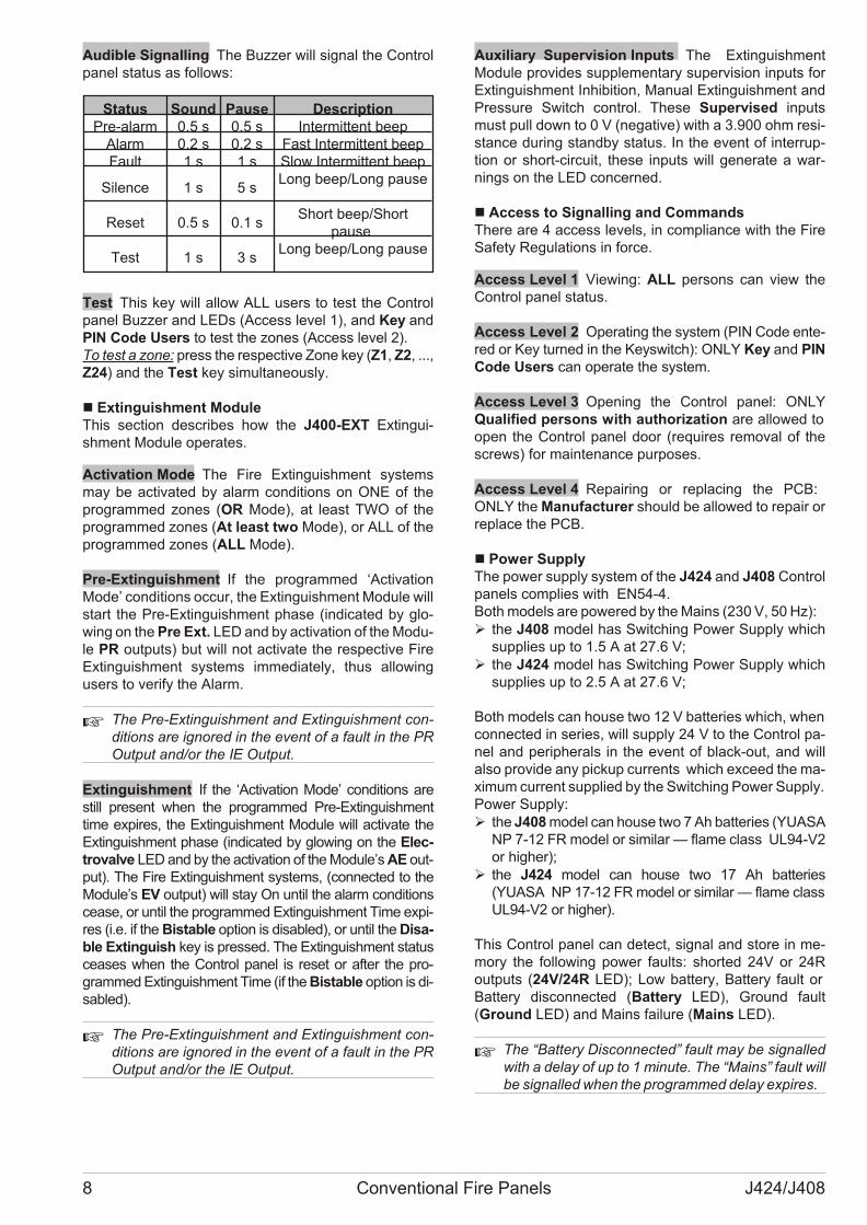
Audible Signalling The Buz zer will si gnal the Con trolpa nel sta tus as fol lows:
Status Sound Pause DescriptionPre-alarm 0.5 s 0.5 s Intermittent beep
Alarm 0.2 s 0.2 s Fast Intermittent beepFault 1 s 1 s Slow Intermittent beep
Silence 1 s 5 sLong beep/Long pause
Reset 0.5 s 0.1 sShort beep/Short
pause
Test 1 s 3 sLong beep/Long pause
Test This key will al low ALL users to test the Con trolpa nel Buz zer and LEDs (Access le vel 1), and Key andPIN Code Users to test the zo nes (Access le vel 2).To test a zone: press the re spec ti ve Zone key (Z1, Z2, ...,Z24) and the Test key si mul ta ne o usly.
n Extinguishment ModuleThis sec tion de scri bes how the J400-EXT Extin gui -shment Mo du le ope ra tes.
Activation Mode The Fire Extin gui shment systemsmay be ac ti va ted by alarm con di tions on ONE of thepro gram med zo nes (OR Mode), at le ast TWO of thepro gram med zo nes (At le ast two Mode), or ALL of thepro gram med zo nes (ALL Mode).
Pre-Extinguishment If the pro gram med ‘Acti va tionMo de’ con di tions oc cur, the Extin gui shment Mo du le will start the Pre-Extin gui shment pha se (in di ca ted by glo -wing on the Pre Ext. LED and by ac ti va tion of the Mo du -le PR out puts) but will not ac ti va te the re spec ti ve FireExtin gui shment systems im me dia tely, thus al lo wingusers to ve rify the Alarm.
+ The Pre-Extin gui shment and Extin gui shment con -di tions are igno red in the event of a fa ult in the PROut put and/or the IE Out put.
Extinguishment If the ‘Acti va tion Mo de’ con di tions arestill pre sent when the pro gram med Pre-Extin gui shmenttime ex pi res, the Extin gui shment Mo du le will ac ti va te theExtin gui shment pha se (in di ca ted by glo wing on the Elec -tro val ve LED and by the ac ti va tion of the Mo du le’s AE out -put). The Fire Extin gui shment systems, (con nec ted to theMo du le’s EV out put) will stay On un til the alarm con di tionsce a se, or un til the pro gram med Extin gui shment Time ex pi -res (i.e. if the Bi sta ble op tion is di sa bled), or un til the Di sa -ble Extin guish key is pres sed. The Extin gui shment sta tusce a ses when the Con trol pa nel is re set or af ter the pro -gram med Extin gui shment Time (if the Bi sta ble op tion is di -sa bled).
+ The Pre-Extin gui shment and Extin gui shment con -di tions are igno red in the event of a fa ult in the PROut put and/or the IE Out put.
Auxiliary Supervision Inputs The Extin gui shmentMo du le pro vi des sup ple men tary su per vi sion in puts forExtin gui shment Inhi bi tion, Ma nual Extin gui shment andPres su re Switch con trol. The se Su per vi sed in putsmust pull down to 0 V (ne ga ti ve) with a 3.900 ohm re si -stan ce du ring standby sta tus. In the event of in ter rup -tion or short-cir cu it, the se in puts will ge ne ra te a war -nings on the LED con cer ned.
n Access to Signalling and CommandsThe re are 4 ac cess le vels, in com plian ce with the FireSa fety Re gu la tions in for ce.
Access Level 1 Vie wing: ALL per sons can view theCon trol pa nel sta tus.
Access Level 2 Ope ra ting the system (PIN Code en te -red or Key tur ned in the Key switch): ONLY Key and PINCode Users can ope ra te the system.
Access Level 3 Ope ning the Con trol pa nel: ONLYQua li fied per sons with aut ho ri za tion are al lo wed to open the Con trol pa nel door (re qui res re mo val of thescrews) for ma in te nan ce pur po ses.
Access Level 4 Re pa i ring or re pla cing the PCB: ONLY the Ma nu fac tu rer sho uld be al lo wed to re pa ir orre pla ce the PCB.
n Power SupplyThe po wer supply system of the J424 and J408 Con trolpa nels com plies with EN54-4. Both mo dels are po we red by the Ma ins (230 V, 50 Hz):Ø the J408 mo del has Swit ching Po wer Supply which
sup plies up to 1.5 A at 27.6 V;Ø the J424 mo del has Swit ching Po wer Supply which
sup plies up to 2.5 A at 27.6 V;
Both mo dels can ho u se two 12 V bat te ries which, when con nec ted in se ries, will supply 24 V to the Con trol pa -nel and pe rip he rals in the event of black-out, and willalso pro vi de any pic kup cur rents which ex ce ed the ma -xi mum cur rent sup plied by the Swit ching Po wer Supply.Po wer Supply:Ø the J408 mo del can ho u se two 7 Ah bat te ries (YUASA
NP 7-12 FR mo del or si mi lar — fla me class UL94-V2or hi gher);
Ø the J424 mo del can ho u se two 17 Ah bat te ries(YUASA NP 17-12 FR mo del or si mi lar — fla me class UL94-V2 or hi gher).
This Con trol pa nel can de tect, si gnal and sto re in me -mory the fol lo wing po wer fa ults: shor ted 24V or 24Rout puts (24V/24R LED); Low bat tery, Bat tery fa ult or Bat tery di scon nec ted (Bat tery LED), Gro und fa ult(Gro und LED) and Ma ins fa i lu re (Ma ins LED).
+ The “Bat tery Di scon nec ted” fa ult may be si gnal ledwith a de lay of up to 1 mi nu te. The “Ma ins” fa ult willbe si gnal led when the pro gram med de lay ex pi res.
8 Conventional Fire Panels J424/J408
IDENTIFICATION OF PARTS
The Status LEDs
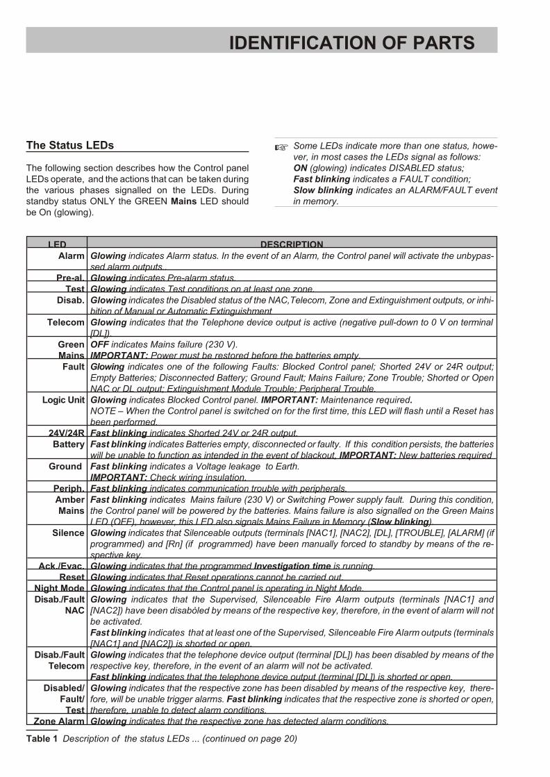
The fol lo wing sec tion de scri bes how the Con trol pa nelLEDs ope ra te, and the ac tions that can be ta ken du ring the va rio us pha ses si gnal led on the LEDs. Du ringstandby sta tus ONLY the GREEN Ma ins LED sho uldbe On (glo wing).
+ Some LEDs in di ca te more than one sta tus, ho we -ver, in most ca ses the LEDs si gnal as fol lows: ON (glo wing) in di ca tes DISABLED sta tus; Fast blin king in di ca tes a FAULT con di tion; Slow blin king in di ca tes an ALARM/FAULT eventin me mory.
LED DESCRIPTIONAlarm Glo wing in di ca tes Alarm sta tus. In the event of an Alarm, the Con trol pa nel will ac ti va te the unbypas -
sed alarm outputs..Pre-al. Glo wing in di ca tes Pre-alarm status.
Test Glo wing in di ca tes Test con di tions on at le ast one zone.Disab. Glo wing in di ca tes the Disabled sta tus of the NAC,Te le com, Zone and Extin gui shment out puts, or in hi -
bi tion of Ma nual or Au to ma tic Extin gui shment Telecom Glo wing in di ca tes that the Te lep ho ne de vi ce out put is ac ti ve (nega ti ve pull-down to 0 V on ter mi nal
[DL]).GreenMains
OFF in di ca tes Ma ins fa i lu re (230 V). IMPORTANT: Po wer must be re sto red be fo re the bat te ries empty.
Fault Glo wing in di ca tes one of the fol lo wing Fa ults: Bloc ked Con trol pa nel; Shor ted 24V or 24R out put;Empty Bat te ries; Di scon nec ted Bat tery; Gro und Fa ult; Ma ins Fa i lu re; Zone Tro u ble; Shor ted or OpenNAC or DL out put; Extin gui shment Module Tro u ble; Pe rip he ral Tro u ble.
Logic Unit Glo wing in di ca tes Bloc ked Con trol pa nel. IMPORTANT: Ma in te nan ce re qui red.NOTE – When the Con trol pa nel is swit ched on for the first time, this LED will flash un til a Re set hasbeen per for med.
24V/24R Fast blin king in di ca tes Shor ted 24V or 24R out put.Battery Fast blin king in di ca tes Bat te ries empty, di scon nec ted or fa ulty. If this con di tion per sists, the bat te ries
will be una ble to fun ction as in ten ded in the event of blac ko ut, IMPORTANT: New bat te ries requiredGround Fast blin king in di ca tes a Vol ta ge le a ka ge to Earth.
IMPORTANT: Check wi ring insu la tion.Periph. Fast blin king in di ca tes com mu ni ca tion tro u ble with pe rip he rals.AmberMains
Fast blin king in di ca tes Ma ins fa i lu re (230 V) or Swit ching Po wer supply fa ult. Du ring this con di tion,the Con trol pa nel will be po we red by the bat te ries. Ma ins fa i lu re is also si gnal led on the Gre en Ma insLED (OFF), ho we ver, this LED also si gnals Ma ins Fa i lu re in Me mory (Slow blin king).
Silence Glo wing in di ca tes that Si len ce a ble out puts (ter mi nals [NAC1], [NAC2], [DL], [TROUBLE], [ALARM] (ifpro gram med) and [Rn] (if pro gram med) have been ma nually for ced to standby by me ans of the re -spec ti ve key.
Ack./Evac. Glo wing in di ca tes that the pro gram med Inve sti ga tion time is run ning.Reset Glo wing in di ca tes that Re set ope ra tions can not be car ried out.
Night Mode Glo wing in di ca tes that the Con trol pa nel is ope ra ting in Night Mode.Disab./Fault
NACGlo wing in di ca tes that the Su per vi sed, Si len ce a ble Fire Alarm out puts (ter mi nals [NAC1] and[NAC2]) have been disabòled by me ans of the re spec ti ve key, the re fo re, in the event of alarm will notbe ac ti va ted.Fast blin king in di ca tes that at le ast one of the Su per vi sed, Si len ce a ble Fire Alarm out puts (ter mi nals [NAC1] and [NAC2]) is shor ted or open.
Disab./FaultTelecom
Glo wing in di ca tes that the te lep ho ne de vi ce out put (ter mi nal [DL]) has been di sa bled by me ans of there spec ti ve key, the re fo re, in the event of an alarm will not be ac ti va ted.Fast blin king in di ca tes that the te lep ho ne de vi ce out put (ter mi nal [DL]) is shor ted or open.
Disabled/Fault/
Test
Glo wing in di ca tes that the re spec ti ve zone has been disabled by me ans of the re spec ti ve key, the re -fo re, will be una ble trig ger alarms. Fast blin king in di ca tes that the re spec ti ve zone is shor ted or open,the re fo re, una ble to de tect alarm con di tions.
Zone Alarm Glo wing in di ca tes that the re spec ti ve zone has de tec ted alarm con di tions.
Ta ble 1 De scrip tion of the sta tus LEDs ... (con ti nu ed on page 20)
BB
MSACMBLIJ408-8 0.0
Extinguish. AutomaticExtinguish.
ManualExtinguish.
Electro-valve
PreExt.
ManualExt.
Disab.Ext.
Pres.Switch
LogicUnit
Disable
Fault
ON
®
408
MSACMNEIJ408-8 0.0
Fault
LogicUnit
Battery
Ground
Mains
Periph.
Pre-al.
Disab.
Mains
Telecom
Test
Silence Night Mode
Ack./Evac. Disab./FaultNAC
Reset Disab./FaultTelecom
Disab. Buzzer Test
1 2 3
5
8
0
4
7
9
6
Disabled/Fault/Test Disabled/Fault/Test
z1 z5
z4 z8
z3 z7
z2 z6
Zone Alarm Zone Alarm
24V/24R
Alarm
MSACMBLIJ424-8 0.0
Esc
Enter
Fault
LogicUnit
Battery
Ground
Mains
Periph.
Pre-al.
Disab.
Mains
Telecom
Test
Silence Night Mode
Ack./Evac. Disab./FaultNAC
Reset Disab./FaultTelecom
Disab. Buzzer Test
1 2 3
5
8
0
4
7
9
6
Disabled/Fult/Test Disabled/Fult/Test
z1 z5
z4 z8
z3 z7
z2 z6
Zone Alarm Zone Alarm
24V/24R
Alarm
Disabled/Fult/Test Disabled/Fult/Test
z9 z13
z12 z16
z11 z15
z10 z14
Zone Alarm Zone Alarm
Disabled/Fult/Test Disabled/Fult/Test
z17 z21
z20 z24
z19 z23
z18 z22
Zone Alarm Zone Alarm
®
424
Extinguish. AutomaticExtinguish.
ManualExtinguish.
Electro-valve
Pre-Ext.
ManualExt.
Disab.Ext.
Pres.Switch
LogicUnit
Disable
Fault
ON
Extinguish. AutomaticExtinguish.
ManualExtinguish.
Electro-valve
PreExt.
ManualExt.
Disab.Ext.
Pres-Switch
LogicUnit
Disable
Fault
ON
Livello 2
MSACMBLIJ400-REP a.0
Esc
Enter
Fault
LogicUnit
Battery
Ground
Mains
Periph.
Pre-al.
Disab.
Mains
Telecom
Test
Silence Night Mode
Ack./Evac. Disab./FaultNAC
Reset Disab./FaultTelecom
Disab. Buzzer Test
1 2 3
5
8
0
4
7
9
6
Disabled/Fault/Test Disabled/Fault/Test
z1 z5
z4 z8
z3 z7
z2 z6
Zone Alarm Zone Alarm
24V/24R
Alarm
Disabled/Fault/Test Disabled/Fault/Test
z9 z13
z12 z16
z11 z15
z10 z14
Zone Alarm Zone Alarm
Disabled/Fault/Test Disabled/Fault/Test
z17 z21
z20 z24
z19 z23
z18 z22
Zone Alarm Zone Alarm
®
Livello 2
400 REPREP
5 1 2 2 4
4
1
4
2 1 2 3 4 1
2512
1a) b)4 4
4 435 2c)
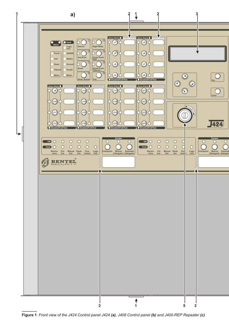
Fi gu re 1 Fron t view of the J424 Con trol pa nel J424 (a), J408 Con trol pa nel (b) and J400-REP Re pe a ter (c)

BB
MSACMBLIJ408-8 0.0
Extinguish. AutomaticExtinguish.
ManualExtinguish.
Electro-valve
PreExt.
ManualExt.
Disab.Ext.
Pres.Switch
LogicUnit
Disable
Fault
ON
®
408
MSACMNEIJ408-8 0.0
Fault
LogicUnit
Battery
Ground
Mains
Periph.
Pre-al.
Disab.
Mains
Telecom
Test
Silence Night Mode
Ack./Evac. Disab./FaultNAC
Reset Disab./FaultTelecom
Disab. Buzzer Test
1 2 3
5
8
0
4
7
9
6
Disabled/Fault/Test Disabled/Fault/Test
z1 z5
z4 z8
z3 z7
z2 z6
Zone Alarm Zone Alarm
24V/24R
Alarm
MSACMBLIJ424-8 0.0
Esc
Enter
Fault
LogicUnit
Battery
Ground
Mains
Periph.
Pre-al.
Disab.
Mains
Telecom
Test
Silence Night Mode
Ack./Evac. Disab./FaultNAC
Reset Disab./FaultTelecom
Disab. Buzzer Test
1 2 3
5
8
0
4
7
9
6
Disabled/Fult/Test Disabled/Fult/Test
z1 z5
z4 z8
z3 z7
z2 z6
Zone Alarm Zone Alarm
24V/24R
Alarm
Disabled/Fult/Test Disabled/Fult/Test
z9 z13
z12 z16
z11 z15
z10 z14
Zone Alarm Zone Alarm
Disabled/Fult/Test Disabled/Fult/Test
z17 z21
z20 z24
z19 z23
z18 z22
Zone Alarm Zone Alarm
®
424
Extinguish. AutomaticExtinguish.
ManualExtinguish.
Electro-valve
Pre-Ext.
ManualExt.
Disab.Ext.
Pres.Switch
LogicUnit
Disable
Fault
ON
Extinguish. AutomaticExtinguish.
ManualExtinguish.
Electro-valve
PreExt.
ManualExt.
Disab.Ext.
Pres-Switch
LogicUnit
Disable
Fault
ON
Livello 2
MSACMBLIJ400-REP a.0
Esc
Enter
Fault
LogicUnit
Battery
Ground
Mains
Periph.
Pre-al.
Disab.
Mains
Telecom
Test
Silence Night Mode
Ack./Evac. Disab./FaultNAC
Reset Disab./FaultTelecom
Disab. Buzzer Test
1 2 3
5
8
0
4
7
9
6
Disabled/Fault/Test Disabled/Fault/Test
z1 z5
z4 z8
z3 z7
z2 z6
Zone Alarm Zone Alarm
24V/24R
Alarm
Disabled/Fault/Test Disabled/Fault/Test
z9 z13
z12 z16
z11 z15
z10 z14
Zone Alarm Zone Alarm
Disabled/Fault/Test Disabled/Fault/Test
z17 z21
z20 z24
z19 z23
z18 z22
Zone Alarm Zone Alarm
®
Livello 2
400 REPREP
5 1 2 2 4
4
1
4
2 1 2 3 4 1
2512
1a) b)4 4
4 435 2c)
Fi gu re 1 Fron t view of the J424 Con trol pa nel J424 (a), J408 Con trol pa nel (b) and J400-REP Re pe a ter (c) IDENTIFICATION OF PARTS 11
Z1 R1 1 2 3
Z2 R2 4 5 6
Z3 R3 7 8 9
Z4 R4 10 11 12
DL
24
V
27
2
82
93
03
1
PL
AL
AR
M
NO
NC
C
TR
OU
BL
E
NO
NC
C-
+-
+
NA
C1
NA
C2
Z5 R5 13 14 15
Z6 R6 16 17 18
Z7 R7 19 20 21
Z8 R8 22 23 24
26
24
R
OC
+-
RS
48
5V 24
PRG
B016
GA
SE
F
R
AC
/NFG
+VG
ND
B+
L
B–
GND
+V
AC
/L
F 3
.1
5A
/25
ØV
F 6
.3
A/2
5Ø
VC
NO
NC
6
20
7 8 10 11 12 13 14 15 17 14 18 12 19
21222324202512262728293031
9
12
16
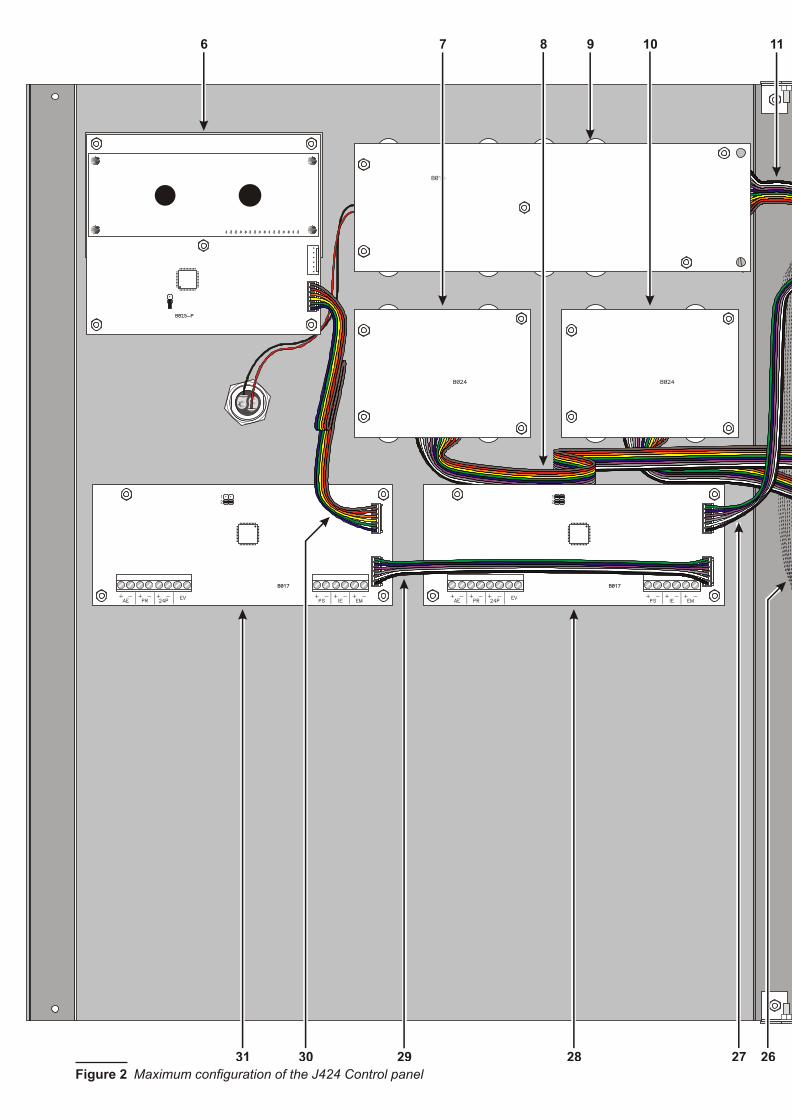
Fi gu re 2 Ma xi mum con fi gu ra tion of the J424 Con trol pa nel
Z1 R1 1 2 3
Z2 R2 4 5 6
Z3 R3 7 8 9
Z4 R4 10 11 12
DL
24
V
27
2
82
93
03
1
PL
AL
AR
M
NO
NC
C
TR
OU
BL
E
NO
NC
C-
+-
+
NA
C1
NA
C2
Z5 R5 13 14 15
Z6 R6 16 17 18
Z7 R7 19 20 21
Z8 R8 22 23 24
26
24
R
OC
+-
RS
48
5V 24
PRG
B016
GA
SE
F
R
AC
/NFG
+VG
ND
B+
L
B–
GND
+V
AC
/L
F 3
.1
5A
/25
ØV
F 6
.3
A/2
5Ø
VC
NO
NC
6
20
7 8 10 11 12 13 14 15 17 14 18 12 19
21222324202512262728293031
9
12
16
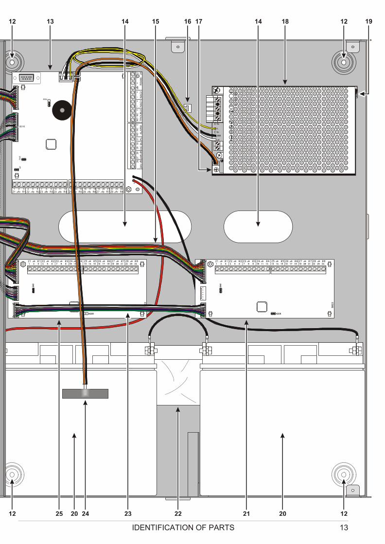
Fi gu re 2 Ma xi mum con fi gu ra tion of the J424 Con trol pa nel IDENTIFICATION OF PARTS 13
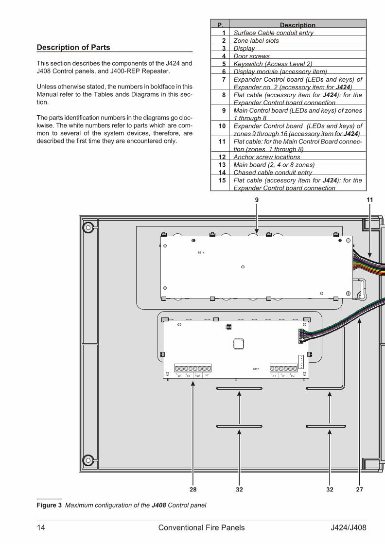
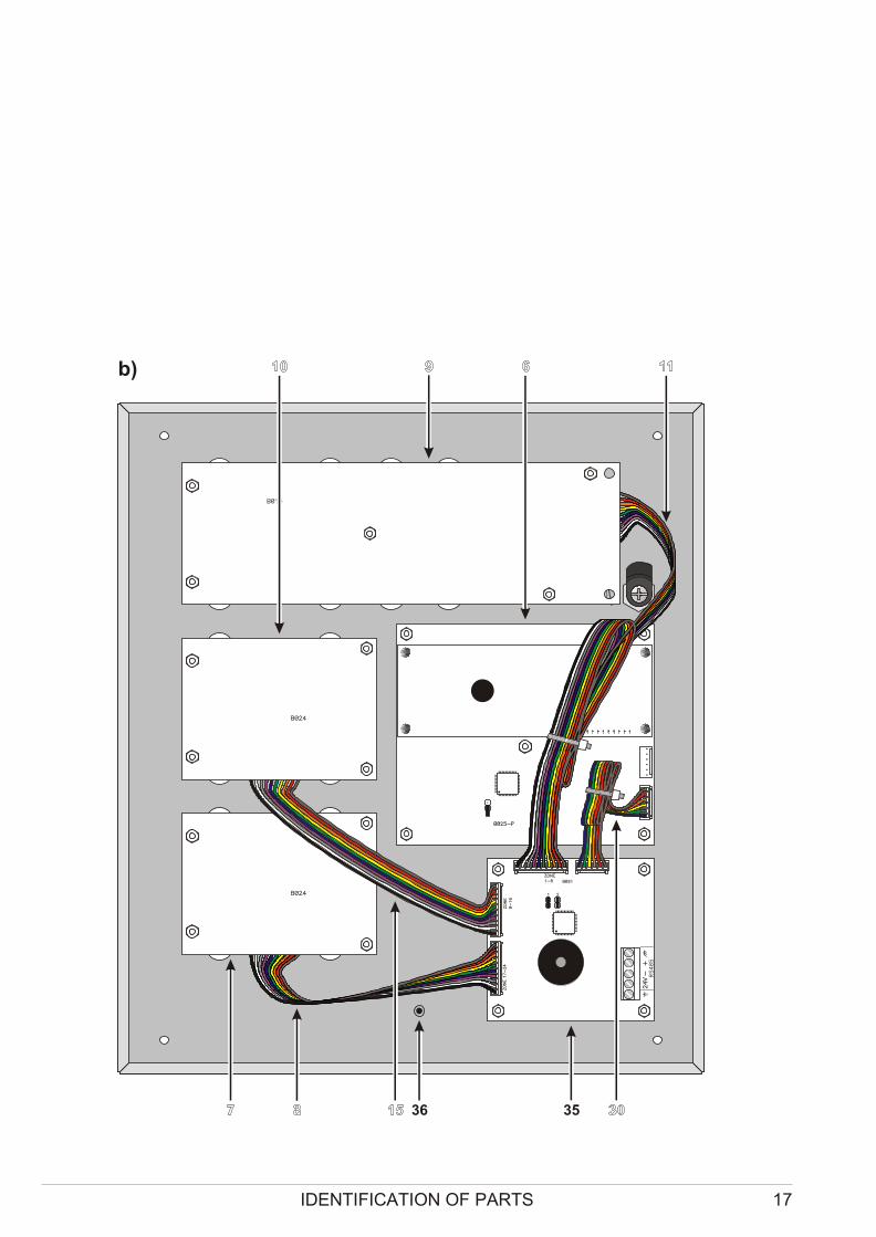
Description of Parts
This sec tion de scri bes the com po nents of the J424 and J408 Con trol pa nels, and J400-REP Re pe a ter.
Unless ot her wi se sta ted, the num bers in bol dfa ce in this Ma nual re fer to the Ta bles ands Dia grams in this sec -tion.
The parts iden ti fi ca tion num bers in the dia grams go cloc -kwi se. The whi te num bers re fer to parts which are com -mon to se ve ral of the system de vi ces, the re fo re, arede scri bed the first time they are en co un te red only.
P. Description1 Sur fa ce Ca ble con du it entry2 Zone la bel slots 3 Di splay4 Door screws5 Key switch (Access Le vel 2)6 Di splay mo du le (ac ces sory item)7 Expan der Con trol bo ard (LEDs and keys) of
Expan der no. 2 (ac ces sory item for J424)8 Flat ca ble (ac ces sory item for J424): for the
Expan der Con trol bo ard con nec tion 9 Main Con trol bo ard (LEDs and keys) of zo nes
1 thro ugh 810 Expan der Con trol bo ard (LEDs and keys) of
zo nes 9 thro ugh 16 (ac ces sory item for J424)11 Flat ca ble: for the Main Con trol Bo ard con nec -
tion (zo nes 1 thro ugh 8)12 Anchor screw lo ca tions13 Main bo ard (2, 4 or 8 zo nes)14 Cha sed ca ble con du it entry15 Flat ca ble (ac ces sory item for J424): for the
Expan der Con trol bo ard con nec tion
14 Conventional Fire Panels J424/J408
Z1 R1 1 2 3
Z2 R2 4 5 6
Z3 R3 7 8 9
Z4 R4 10 11 12
DL
24
V
27
2
82
93
03
1
PL
AL
AR
M
NO
NC
C
TR
OU
BL
E
NO
NC
C-
+-
+
NA
C1
NA
C2
Z5 R5 13 14 15
Z6 R6 16 17 18
Z7 R7 19 20 21
Z8 R8 22 23 24
26
24
R
OC
+-
RS
48
5V 24
PRG
B016
GA
SE
F
R
AC
/NFG
+VG
ND
B+
L
B–
GND
+V
AC
/L
F 2
A/2
5Ø
V
F 6 . 3 A / 2 5 Ø V
BB
C
NO
NC
9
12
13 12 18
202012323228 27 24
11 17 1916 14
22
Fi gu re 3 Ma xi mum con fi gu ra tion of the J408 Con trol pa nel
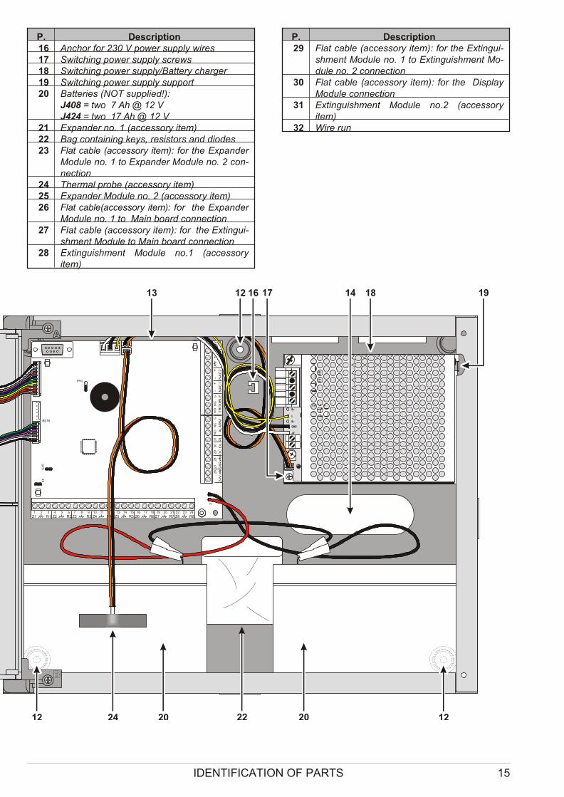
P. Description16 Anchor for 230 V po wer supply wi res17 Swit ching po wer supply screws18 Swit ching po wer supply/Bat tery char ger19 Swit ching po wer supply sup port20 Bat te ries (NOT sup plied!):
J408 = two 7 Ah @ 12 VJ424 = two 17 Ah @ 12 V
21 Expan der no. 1 (ac ces sory item)22 Bag con ta i ning keys, re si stors and dio des23 Flat ca ble (ac ces sory item): for the Expan der
Mo du le no. 1 to Expan der Mo du le no. 2 con -nec tion
24 Ther mal pro be (ac ces sory item)25 Expan der Mo du le no. 2 (ac ces sory item)26 Flat ca ble(ac ces sory item): for the Expan der
Mo du le no. 1 to Main bo ard con nec tion 27 Flat ca ble (ac ces sory item): for the Extin gui -
shment Mo du le to Main bo ard con nec tion 28 Extin gui shment Mo du le no.1 (ac ces sory
item)
P. Description29 Flat ca ble (ac ces sory item): for the Extin gui -
shment Mo du le no. 1 to Extin gui shment Mo -du le no. 2 con nec tion
30 Flat ca ble (ac ces sory item): for the Di splayMo du le con nec tion
31 Extin gui shment Mo du le no.2 (ac ces soryitem)
32 Wire run
IDENTIFICATION OF PARTS 15
Z1 R1 1 2 3
Z2 R2 4 5 6
Z3 R3 7 8 9
Z4 R4 10 11 12
DL
24
V
27
2
82
93
03
1
PL
AL
AR
M
NO
NC
C
TR
OU
BL
E
NO
NC
C-
+-
+
NA
C1
NA
C2
Z5 R5 13 14 15
Z6 R6 16 17 18
Z7 R7 19 20 21
Z8 R8 22 23 24
26
24
R
OC
+-
RS
48
5V 24
PRG
B016
GA
SE
F
R
AC
/NFG
+VG
ND
B+
L
B–
GND
+V
AC
/L
F 2
A/2
5Ø
V
F 6 . 3 A / 2 5 Ø V
BB
C
NO
NC
9
12
13 12 18
202012323228 27 24
11 17 1916 14
22
Fi gu re 3 Ma xi mum con fi gu ra tion of the J408 Con trol pa nel
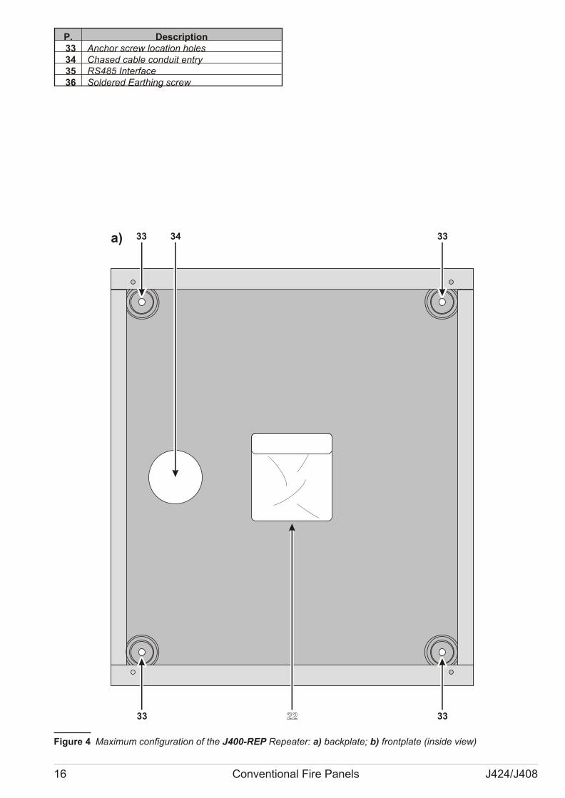
P. Description33 Anchor screw lo ca tion ho les 34 Chased ca ble con du it entry35 RS485 Inter fa ce36 Sol de red Ear thing screw
16 Conventional Fire Panels J424/J408
C
NO
NC
a) 33
33
34 33
33 36 35
b)
Fi gu re 4 Ma xi mum con fi gu ra tion of the J400-REP Re pe a ter: a) backplate; b) frontpla te (in side view)
IDENTIFICATION OF PARTS 17
C
NO
NC
a) 33
33
34 33
33 36 35
b)
Fi gu re 4 Ma xi mum con fi gu ra tion of the J400-REP Re pe a ter: a) backplate; b) frontpla te (in side view)
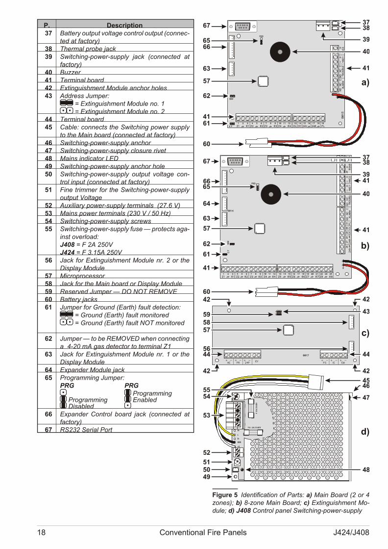
P. Description37 Bat tery out put vol ta ge con trol out put (con nec -
ted at fac tory)38 Ther mal pro be jack39 Swit ching-po wer-supply jack (con nec ted at
fac tory)40 Buz zer41 Ter mi nal bo ard42 Extin gui shment Mo du le an chor ho les 43 Address Jum per:
// = Extin gui shment Mo du le no. 1oo = Extin gui shment Mo du le no. 2
44 Ter mi nal bo ard45 Ca ble: con nects the Swit ching po wer supply
to the Main bo ard (con nec ted at fac tory)46 Swit ching-po wer-supply an chor47 Swit ching-po wer-supply clo su re ri vet48 Ma ins in di ca tor LED 49 Swit ching-po wer-supply an chor hole50 Swit ching-po wer-supply out put vol ta ge con -
trol in put (con nec ted at fac tory)51 Fine trim mer for the Swit ching-po wer-supply
out put Vol ta ge52 Au xi liary po wer-supply ter mi nals (27.6 V)53 Ma ins po wer ter mi nals (230 V / 50 Hz)54 Swit ching-po wer-supply screws55 Swit ching-po wer-supply fuse — pro tects aga -
inst over lo ad:J408 = F 2A 250VJ424 = F 3.15A 250V
56 Jack for Extin gui shment Mo du le nr. 2 or theDi splay Mo du le
57 Mi cro pro ces sor58 Jack for the Main bo ard or Di splay Mo du le59 Re ser ved Jum per — DO NOT REMOVE60 Bat tery jacks61 Jum per for Gro und (Earth) fa ult de tec tion:
// = Gro und (Earth) fa ult mo ni to redoo = Gro und (Earth) fa ult NOT mo ni to red
62 Jum per — to be REMOVED when con nec ting a 4-20 mA gas de tec tor to ter mi nal Z1
63 Jack for Extin gui shment Mo du le nr. 1 or theDi splay Mo du le
64 Expan der Mo du le jack65 Pro gram ming Jum per:
PRG PRGo O Pro gram mingO Pro gram ming O Ena bledO Di sa bled o
66 Expan der Con trol bo ard jack (con nec ted atfac tory)
67 RS232 Se rial Port
18 Conventional Fire Panels J424/J408
AC
/NFG
+VG
ND
B+
L
B–
GND
+V
AC
/L
F 2
A/2
5Ø
V
F 6 . 3 A / 2 5 Ø V
3867
40
41
37
39
3738
3941
40
41
42
43
44
42
45
47
48
6566
63
4161
60
67
66
64
65
63
61
41
6042
5958
5644
42
55
53
52
515049
a)
b)
c)
d)
54
46
57
62
57
62
57
Fi gu re 5 Iden ti fi ca tion of Parts: a) Main Bo ard (2 or 4zo nes); b) 8-zone Main Bo ard; c) Extin gui shment Mo -du le; d) J408 Con trol pa nel Swit ching-po wer-supply
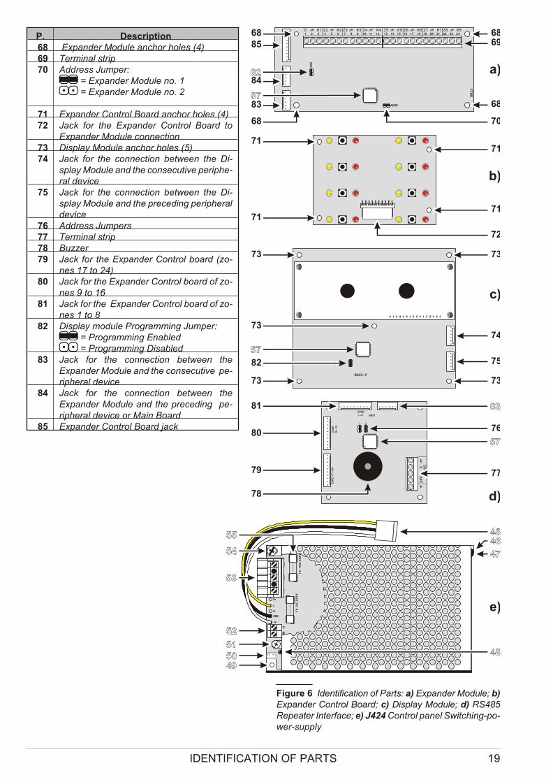
P. Description68 Expan der Mo du le an chor ho les (4)69 Ter mi nal strip70 Address Jum per:
// = Expan der Mo du le no. 1oo = Expan der Mo du le no. 2
71 Expan der Con trol Bo ard an chor ho les (4) 72 Jack for the Expan der Con trol Bo ard to
Expan der Mo du le con nec tion73 Di splay Mo du le an chor ho les (5)74 Jack for the con nec tion bet we en the Di -
splay Mo du le and the con se cu ti ve pe rip he -ral de vi ce
75 Jack for the con nec tion bet we en the Di -splay Mo du le and the pre ce ding pe rip he ral de vi ce
76 Address Jum pers77 Ter mi nal strip78 Buz zer79 Jack for the Expan der Con trol bo ard (zo -
nes 17 to 24)80 Jack for the Expan der Con trol bo ard of zo -
nes 9 to 1681 Jack for the Expan der Con trol bo ard of zo -
nes 1 to 882 Di splay module Pro gram ming Jum per:
// = Pro gram ming Enabledoo = Pro gram ming Disabled
83 Jack for the con nec tion bet we en theExpan der Mo du le and the con se cu ti ve pe -rip he ral de vi ce
84 Jack for the con nec tion bet we en theExpan der Mo du le and the pre ce ding pe -rip he ral de vi ce or Main Bo ard
85 Expan der Con trol Bo ard jack
IDENTIFICATION OF PARTS 19
AC
/NF
G+V
GN
D
B+
L
B–
GND
+V
AC
/L
F 3
.1
5A
/25
ØV
F 6
.3
A/2
5Ø
V
68 6885
84
83
68
69
68
70
71
72
7171
71
73
74
75
73
73
73
82
73
a)
b)
c)
81
80
79
78
76
77
d)
e)
Fi gu re 6 Iden ti fi ca tion of Par ts: a) Expan der Mo du le; b)Expan der Control Bo ard; c) Di splay Mo du le; d) RS485Re pe a ter Inter fa ce; e) J424 Con trol pa nel Swit ching-po -wer-supply
Description of the Control keys
The Con trol pa nel keys can be ac ti va ted by Key switchand PIN Code Users ONLY (Access le vel 2 — Key tur -
ned in key switch or PIN Code en te red — re fer to“Access to Si gnal ling and Com mands”), un less ot her wi -se sta ted.
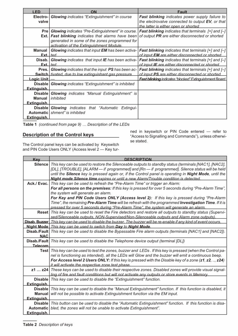
LED ON FaultElectro-
valveGlo wing in di ca tes “Extin gui shment” in co ur se Fast blin king in di ca tes po wer supply fa i lu re to
the elec tro val ve con nec ted to out put EV, or thatthe lat ter is eit her open or shor ted
PreExt.
Glo wing in di ca tes “Pre-Extin gui shment” in co ur se.Fast blin king in di ca tes that alarms have beenge ne ra ted in some of the zo nes pro gram med forac ti va tion of the Extin gui shment Mo du le.
Fast blin king in di ca tes that ter mi nals [+] and [–]of out put PR are eit her di scon nec ted or shor ted
Manual Ext.
Glo wing in di ca tes that in put EM has been ac ti va -ted
Fast blin king in di ca tes that ter mi nals [+] and [–]of in put EM are eit her di scon nec ted or shor ted
Disab.Ext.
Glo wing in di ca tes that in put IE has been ac ti va -ted
Fast blin king in di ca tes that ter mi nals [+] and [–]of in put IE are eit her di scon nec ted or shor ted
Pres.Switch
Glo wing in di ca tes that the in put PS has been ac -ti va ted, due to low ex tin gui shant gas pres su re
Fast blin king in di ca tes that ter mi nals [+] and [–]of in put PS are eit her di scon nec ted or shor ted
Logic Unit — Fast blin king in di ca tes “bloc ked” Extin gui shment Bo ardDisable
Extinguish.Glo wing in di ca tes “Extin gui shment” is inhibited
DisableManual
Extinguish.
Glo wing in di ca tes “Ma nual Extin gui shment” isinhibited
DisableAutomatic
Extinguish.
Glo wing in di ca tes that “Au to ma tic Extin gui -shment” is in hi bi ted
Ta ble 1 (con ti nu ed from page 9) … De scrip tion of the LEDs
Key DESCRIPTIONSilence This key can be used to re sto re the Si len ce a ble out puts to standby sta tus (ter mi nals [NAC1], [NAC2],
[DL], [TROUBLE], [ALARM — if pro gram med] and [Rn — if pro gram med]. Si len ce sta tus will be heldun til the Si len ce key is pres sed aga in or, if the Con trol pa nel is ope ra ting in Night Mode, un til theNight mode Si len ce time ex pi res or un til a new Alarm/Tro u ble con di tion is de tec ted.
Ack./ Evac. This key can be used to re fresh the “Pre-Alarm Time” or trig ger an Alarm: For all per sons on the pre mi ses: If this key is pres sed for over 5 se conds du ring “Pre-Alarm Time”,the system will ge ne ra te an alarm. For Key and PIN Code Users ONLY (Access le vel 2): If this key is pres sed du ring “Pre-AlarmTime”, the re ma i ning Pre-Alarm Time will be re fresh with the pro gram med Inve sti ga tion Time. If it is pres sed for over 5 se conds du ring “Pre-Alarm Time”, the system will ge ne ra te an alarm.
Reset This key can be used to re set the Fire de tec tors and re sto re all out puts to standby sta tus (Su per vi -sed/Si len ce a ble out puts, NON-Su per vi sed/Non-Si len ce a ble out puts and Alarm zone out puts).
Disab. Buzzer This key can be used to di sa ble the buz zer. The buz zer will be re-ena ble if any kind of event oc curs.Night Mode This key can be used to switch from Day to Night Mode.Disab./Fault
NACThis key can be used to di sa ble the Bypas sa ble Fire alarm out puts (ter mi nals [NAC1] and [NAC2]).
Disab./FaultTelecom
This key can be used to di sa ble the Te lep ho ne de vi ce out put (ter mi nal [DL])
Test This key can be used to test the zo nes, buz zer and LEDs . If this key is pres sed (when the Con trol pa -nel is fun ctio ning as in ten ded), all the LEDs will Glow and the buz zer will emit a con ti nu o us beep.For Access le vel 2 Users ONLY: If this key is pres sed with the Di sa ble key of a zone (z1, z2, .., z24) it will ac ti va te the re spec ti ve zone test pha se.
z1 … z24 The se keys can be used to di sa ble the ir re spec ti ve zo nes. Di sa bled zo nes will pro vi de vi sual si gnal -ling of fire and fa ult con di tions but will not ac ti va te any out puts or sto re events in Me mory.
Disable Extinguish.
This key can be used to di sa ble the “Extin gui shment” fun ction.
DisableManual
Extinguish.
This key can be used to di sa ble the “Ma nual Extin gui shment” fun ction. If this fun ction is di sa bled, itwill not be pos si ble to ac ti va te Extin gui shment fun ction via the EM in put.
DisableAutomatic
Extinguish.
This but ton can be used to di sa ble the “Au to ma tic Extin gui shment” fun ction. If this fun ction is di sa -bled, the zo nes will not be una ble to ac ti va te Extin gui shment”.
Ta ble 2 De scrip tion of keys
INSTALLING THE CONTROL PANEL
! Instal la tion of this system must be car ried outstrictly in ac cor dan ce with the in struc tions inthis sec tion, and in com plian ce with the lo calsa fety re gu la tions in for ce.
Ø Cho o se su i ta ble mo un ting lo ca tions for the Con trolpa nel, de tec tors, fire war ning and fire con trol de vi ces.
Ø Lay the ca bles bet we en the Con trol pa nel and thesystem pe rip he rals.
Ø If ne ces sary, in stall any ac ces sory mo du les (Expan -ders, etc.).
Ø Mo unt the Con trol pa nel to the wall.Ø Carry out the ne ces sary con nec tions, le a ving the po -
wer-supply con nec tion un til last.Ø Pro gram the Con trol pa nel in ac cor dan ce with the in -
struc tions in the “PROGRAMMING” sec tion.Ø Test the en ti re system (Con trol pa nel, de tec tors, fire
war ning and fire con trol de vi ces).
+ Acces sory Mo du les (Expan ders Mo du les, Extin -gui shment Mo du les, etc.) sho uld be in stal led be fo -re mo un ting the Con trol pa nel to the wall.
Installing accessory boards
! Ensu re that the Con trol pa nel po wer supply(Ma ins and Bat te ries) has been di scon nec tedbe fo re in stal ling any ac ces sory the Mo du les.
+ Acces sory Mo du les must be en rol led.
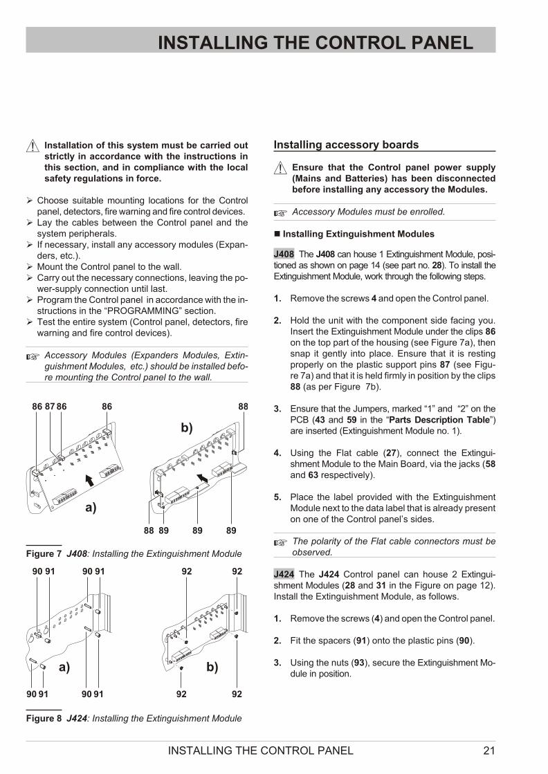
n Installing Extinguishment Modules
J408 The J408 can ho u se 1 Extin gui shment Mo du le, po si -tio ned as shown on page 14 (see part no. 28). To in stall theExtin gui shment Mo du le, work thro ugh the fol lo wing steps.
1. Re mo ve the screws 4 and open the Con trol pa nel.
2. Hold the unit with the com po nent side fa cing you.Insert the Extin gui shment Mo du le un der the clips 86on the top part of the ho u sing (see Fi gu re 7a), thensnap it gently into pla ce. Ensu re that it is re stingpro perly on the pla stic sup port pins 87 (see Fi gu -re 7a) and that it is held firmly in po si tion by the clips88 (as per Fi gu re 7b).
3. Ensu re that the Jum pers, mar ked “1” and “2” on thePCB (43 and 59 in the “Parts De scrip tion Ta ble”)are in ser ted (Extin gui shment Mo du le no. 1).
4. Using the Flat ca ble (27), con nect the Extin gui -shment Mo du le to the Main Bo ard, via the jacks (58and 63 re spec ti vely).
5. Pla ce the la bel pro vi ded with the Extin gui shmentMo du le next to the data la bel that is al re ady pre sent on one of the Con trol pa nel’s sides.
+ The po la rity of the Flat ca ble con nec tors must beob ser ved.
J424 The J424 Con trol pa nel can ho u se 2 Extin gui -shment Mo du les (28 and 31 in the Fi gu re on page 12).Install the Extin gui shment Mo du le, as fol lows.
1. Re mo ve the screws (4) and open the Con trol pa nel.
2. Fit the spa cers (91) onto the pla stic pins (90).
3. Using the nuts (93), se cu re the Extin gui shment Mo -du le in po si tion.
INSTALLING THE CONTROL PANEL 21
86
a)
b)
87 86 86 88
88 89 89 89
Fi gu re 7 J408: Instal ling the Extin gui shment Mo du le
90
a) b)
91 90 91
90 91 90 91
92 92
92 92
Fi gu re 8 J424: Instal ling the Extin gui shment Module
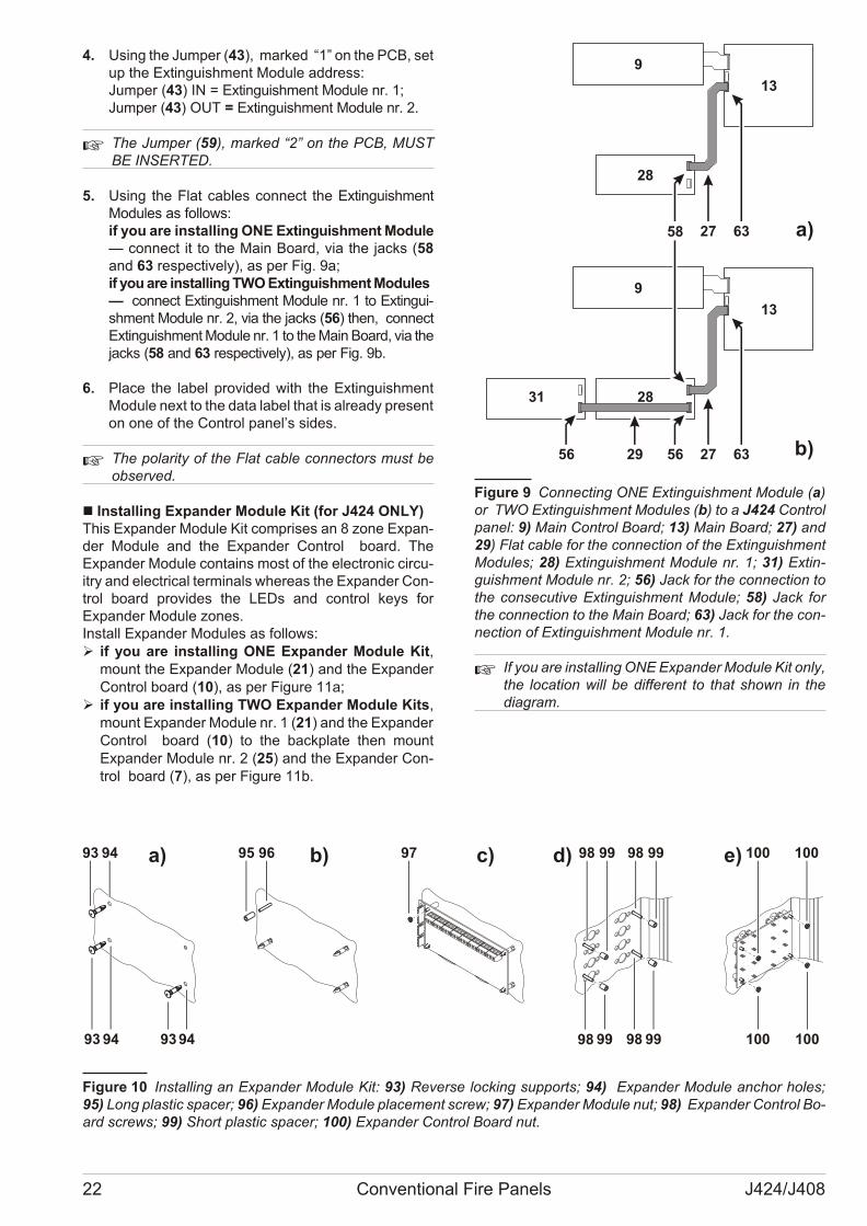
4. Using the Jum per (43), mar ked “1” on the PCB, set up the Extin gui shment Mo du le ad dress:Jum per (43) IN = Extin gui shment Mo du le nr. 1;Jum per (43) OUT = Extin gui shment Mo du le nr. 2.
+ The Jum per (59), mar ked “2” on the PCB, MUSTBE INSERTED.
5. Using the Flat ca bles con nect the Extin gui shmentMo du les as fol lows:if you are in stal ling ONE Extin gui shment Mo du le— con nect it to the Main Bo ard, via the jacks (58and 63 re spec ti vely), as per Fig. 9a;if you are in stal ling TWO Extin gui shment Mo du les — con nect Extin gui shment Mo du le nr. 1 to Extin gui -shment Mo du le nr. 2, via the jacks (56) then, con nectExtin gui shment Mo du le nr. 1 to the Main Bo ard, via the jacks (58 and 63 re spec ti vely), as per Fig. 9b.
6. Pla ce the la bel pro vi ded with the Extin gui shmentMo du le next to the data la bel that is al re ady pre sent on one of the Con trol pa nel’s si des.
+ The po la rity of the Flat ca ble con nec tors must beob ser ved.
n Installing Expander Module Kit (for J424 ONLY)This Expan der Mo du le Kit com pri ses an 8 zone Expan -der Mo du le and the Expan der Con trol bo ard. TheExpan der Mo du le con ta ins most of the elec tro nic cir cu -itry and elec tri cal ter mi nals whe re as the Expan der Con -trol bo ard pro vi des the LEDs and con trol keys forExpan der Mo du le zo nes.Install Expan der Mo du les as fol lows: Ø if you are in stal ling ONE Expan der Mo du le Kit,
mo unt the Expan der Mo du le (21) and the Expan derCon trol bo ard (10), as per Fi gu re 11a;
Ø if you are in stal ling TWO Expan der Mo du le Kits,mo unt Expan der Mo du le nr. 1 (21) and the Expan der Con trol bo ard (10) to the backpla te then mo untExpan der Mo du le nr. 2 (25) and the Expan der Con -trol bo ard (7), as per Fi gu re 11b.
+ If you are in stal ling ONE Expan der Mo du le Kit only, the lo ca tion will be dif fe rent to that shown in thedia gram.
22 Conventional Fire Panels J424/J408
13
9
28
31
13
9
28
a)
b)
27 6358
27 6356 29 56
Fi gu re 9 Con nec ting ONE Extin gui shment Mo du le (a)or TWO Extin gui shment Mo du les (b) to a J424 Con trolpa nel: 9) Main Con trol Bo ard; 13) Main Bo ard; 27) and29) Flat ca ble for the con nec tion of the Extin gui shmentMo du les; 28) Extin gui shment Mo du le nr. 1; 31) Extin -gui shment Mo du le nr. 2; 56) Jack for the con nec tion tothe con se cu ti ve Extin gui shment Mo du le; 58) Jack forthe con nec tion to the Main Bo ard; 63) Jack for the con -nec tion of Extin gui shment Mo du le nr. 1.
93
93
95 96 97 98 99 98 99 100 100
93 98 99 98 99 100 100
a) b) c) d) e)94
94 94
Fi gu re 10 Instal ling an Expan der Mo du le Kit: 93) Re ver se loc king sup ports; 94) Expan der Mo du le an chor ho les;95) Long pla stic spa cer; 96) Expan der Mo du le pla ce ment screw; 97) Expan der Mo du le nut; 98) Expan der Con trol Bo -ard screws; 99) Short pla stic spa cer; 100) Expan der Con trol Bo ard nut.
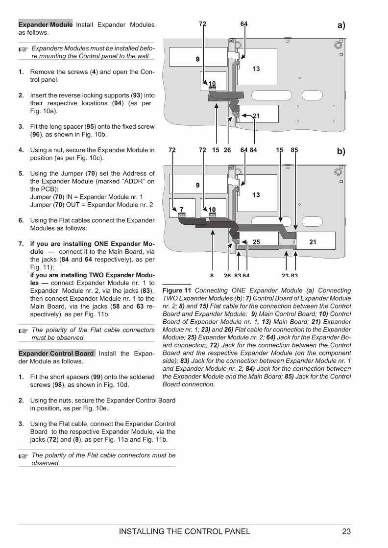
Expander Module Install Expan der Mo du lesas fol lows.
+ Expan ders Mo du les must be in stal led be fo -re mo un ting the Con trol pa nel to the wall.
1. Re mo ve the screws (4) and open the Con -trol pa nel.
2. Insert the re ver se loc king sup ports (93) intothe ir re spec ti ve lo ca tions (94) (as per Fig. 10a).
3. Fit the long spa cer (95) onto the fi xed screw(96), as shown in Fig. 10b.
4. Using a nut, se cu re the Expan der Mo du le inpo si tion (as per Fig. 10c).
5. Using the Jum per (70) set the Address ofthe Expan der Mo du le (mar ked “ADDR” onthe PCB):Jum per (70) IN = Expan der Mo du le nr. 1Jum per (70) OUT = Expan der Mo du le nr. 2
6. Using the Flat ca bles con nect the Expan derMo du les as fol lows:
7. if you are in stal ling ONE Expan der Mo -du le — con nect it to the Main Bo ard, viathe jacks (84 and 64 re spec ti vely), as perFig. 11);if you are in stal ling TWO Expan der Mo du -les — con nect Expan der Mo du le nr. 1 toExpan der Mo du le nr. 2, via the jacks (83), then con nect Expan der Mo du le nr. 1 to theMain Bo ard, via the jacks (58 and 63 re -spec ti vely), as per Fig. 11b.
+ The po la rity of the Flat ca ble con nec torsmust be ob ser ved.
Expander Control Board Install the Expan -der Mo du le as fol lows.
1. Fit the short spa cers (99) onto the sol de redscrews (98), as shown in Fig. 10d.
2. Using the nuts, se cu re the Expan der Con trol Bo ardin po si tion, as per Fig. 10e.
3. Using the Flat ca ble, con nect the Expan der Con trolBo ard to the re spec ti ve Expan der Mo du le, via thejacks (72) and (8), as per Fig. 11a and Fig. 11b.
+ The po la rity of the Flat ca ble con nec tors must beob ser ved.
INSTALLING THE CONTROL PANEL 23
99
21
21
25
101077
13
1313
9
72 72 64 15 85
8 26 83 84 23 83
99
10
72
842615 b)
a)64
Fi gu re 11 Con nec ting ONE Expan der Mo du le (a) Con nec tingTWO Expan der Mo du les (b): 7) Con trol Bo ard of Expan der Mo du le nr. 2; 8) and 15) Flat ca ble for the con nec tion bet we en the Con trolBo ard and Expan der Mo du le; 9) Main Con trol Bo ard; 10) Con trolBo ard of Expan der Mo du le nr. 1; 13) Main Bo ard; 21) Expan derMo du le nr. 1; 23) and 26) Flat ca ble for con nec tion to the Expan der Mo du le; 25) Expan der Mo du le nr. 2; 64) Jack for the Expan der Bo -ard con nec tion; 72) Jack for the con nec tion bet we en the Con trolBo ard and the re spec ti ve Expan der Mo du le (on the com po nentside); 83) Jack for the con nec tion bet we en Expan der Mo du le nr. 1and Expan der Mo du le nr. 2; 84) Jack for the con nec tion bet we enthe Expan der Mo du le and the Main Bo ard; 85) Jack for the Con trolBo ard con nec tion.
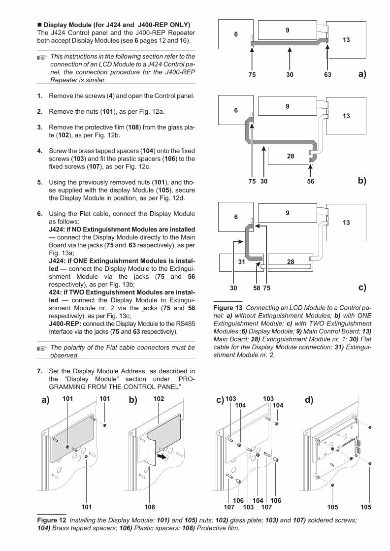
n Display Module (for J424 and J400-REP ONLY)The J424 Con trol pa nel and the J400-REP Re pe a terboth ac cept Di splay Mo du les (see 6 pa ges 12 and 16).
+ This in struc tions in the fol lo wing sec tion re fer to the con nec tion of an LCD Mo du le to a J424 Con trol pa -nel, the con nec tion pro ce du re for the J400-REPRe pe a ter is si mi lar.
1. Re mo ve the screws (4) and open the Con trol pa nel.
2. Re mo ve the nuts (101), as per Fig. 12a.
3. Re mo ve the pro tec ti ve film (108) from the glass pla -te (102), as per Fig. 12b.
4. Screw the brass tap ped spa cers (104) onto the fi xed screws (103) and fit the pla stic spa cers (106) to thefi xed screws (107), as per Fig. 12c.
5. Using the pre vio usly re mo ved nuts (101), and tho -se sup plied with the di splay Mo du le (105), se cu rethe Di splay Mo du le in po si tion, as per Fig. 12d.
6. Using the Flat ca ble, con nect the Di splay Mo du leas fol lows:J424: if NO Extin gui shment Mo du les are in stal led— con nect the Di splay Mo du le di rectly to the MainBo ard via the jacks (75 and 63 re spec ti vely), as per Fig. 13a;J424: if ONE Extin gui shment Mo du les is in stal -led — con nect the Di splay Mo du le to the Extin gui -shment Mo du le via the jacks (75 and 56re spec ti vely), as per Fig. 13b;424: if TWO Extin gui shment Mo du les are in stal -led — con nect the Di splay Mo du le to Extin gui -shment Mo du le nr. 2 via the jacks (75 and 58re spec ti vely), as per Fig. 13c;J400-REP: con nect the Di splay Mo du le to the RS485Inter fa ce via the jacks (75 and 63 re spec ti vely).
+ The po la rity of the Flat ca ble con nec tors must beob ser ved.
7. Set the Di splay Mo du le Address, as de scri bed inthe “Di splay Mo du le” sec tion un der “PRO -GRAMMING FROM THE CONTROL PANEL”
101
107 103 107106 106104
101
101
102
108
103104 104
103
105 105
a) b) c) d)
Fi gu re 12 Instal ling the Di splay Module: 101) and 105) nuts; 102) glass plate; 103) and 107) sol de red screws; 104) Brass tap ped spa cers; 106) Pla stic spacers; 108) Pro tec ti ve film.
6375 30
613
9
5675
613
9
28
31
613
9
28
30
755830
a)
b)
c)
Fi gu re 13 Con nec ting an LCD Mo du le to a Con trol pa -nel: a) wit ho ut Extin gui shment Mo du les; b) with ONEExtin gui shment Mo du le; c) with TWO Extin gui shmentMo du les ;6) Di splay Mo du le; 9) Main Con trol Bo ard; 13)Main Bo ard; 28) Extin gui shment Mo du le nr. 1; 30) Flatca ble for the Di splay Mo du le con nec tion; 31) Extin gui -shment Mo du le nr. 2.
Installing Repeaters
+ The Di splay Mo du le (if used) must be in stal led be -fo re the Re pe a ters.
Re pe a ters can be wall mo un ted, or flush mo un ted to an ave® BL08 out let box (or si mi lar).
Work ca re fully thro ugh the fol lo wing steps.
1. Lay the con nec tion ca bles (re fer to “Con nec tingRe pe a ters”).
2. Re mo ve the screws (4) and open the Con trol pa nel.
3. Take out the bag 22 con ta i ning the Re pe a ter pa nelKeys (Access Le vel 2).
4. If ne ces sary, in stall the Di splay Mo du le as de scri -bed in the “Di splay Mo du le” sec tion.
5. If you are flush mo un ting the Re pe a ter, go to step7. If you are wall mo un ting the Re pe a ter, drill thean chor screw ho les 33.
6. Pull the wi res thro ugh the wire entry 34, then, usingthe an chor screws, se cu re the Re pe a ter to the wall.
7. Com ple te the con nec tions to the ter mi nal bo ard 77of the RS485 Inter fa ce (part nr. 35), as de scri bed inthe “Con nec ting Re pe a ters” sec tion.
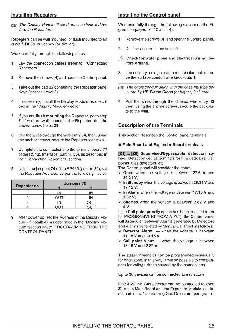
8. Using the jum pers 76 of the RS485 (part nr. 35), set the Re pe a ter Address, as per the fol lo wing Ta ble:
Repeater nr.Jumpers 76
1 21 IN IN2 OUT IN3 IN OUT4 OUT OUT
9. After po wer up, set the Address of the Di splay Mo -du le (if in stal led), as de scri bed in the “Di splay Mo -du le” sec tion un der “PROGRAMMING FROM THECONTROL PANEL”.
Installing the Control panel
Work ca re fully thro ugh the fol lo wing steps (see the Fi -gu res on pa ges 10, 12 and 14).
1. Re mo ve the screws (4) and open the Con trol pa nel.
2. Drill the an chor screw ho les 9.
! Check for wa ter pi pes and elec tri cal wi ring be -fo re dril ling.
3. If ne ces sary, using a ham mer or si mi lar tool, re mo -ve the sur fa ce con du it wire knoc ko uts 1.
+ The ca ble con du it union with the case must be se -cu red by HB Fla me Class (or hi gher) lock nuts.
4. Pull the wi res thro ugh the cha sed wire entry 12then, using the an chor screws, se cu re the backpla -te to the wall.
Description of the Terminals
This sec tion de scri bes the Con trol pa nel ter mi nals.
n Main Board and Expander Board terminals
[Z1] ... [Z8] Su per vi sed/Bypas sa ble de tec tion zo -nes. De tec tion de vi ce ter mi nals for Fire de tec tors, Callpo ints, Gas de tec tors, etc.The Con trol pa nel will con si der the zone: Ø Open when the vol ta ge is bet we en 27.6 V and
26.31 V;Ø In Standby when the vol ta ge is bet we en 26.31 V and
17.15 V;Ø In Alarm when the vol ta ge is bet we en 17.15 V and
2.82 V;Ø Shor ted when the vol ta ge is bet we en 2.82 V and
0 V.If the Call po int prio rity op tion has been ena bled (re ferto “PROGRAMMING FROM A PC”), the Con trol pa nelwill di stin guish bet we en Alarms ge ne ra ted by De tec tors and Alarms ge ne ra ted by Ma nual Call Po int, as fol lows:Ø De tec tor Alarm — when the vol ta ge is bet we en
17.15 V and 13.15 V;Ø Call po int Alarm — when the vol ta ge is bet we en
13.15 V and 2.82 V.
The sta tus thre sholds can be pro gram med in di vi duallyfor each zone, in this way, it will be pos si ble to com pen -sa te for vol ta ge drops ca u sed by the con nec tions.
Up to 30 de vi ces can be con nec ted to each zone.
One 4-20 mA Gas de tec tor can be con nec ted to zoneZ1 of the Main Bo ard and the Expan der Mo du le, as de -scri bed in the “Con nec ting Gas De tec tors” pa ra graph.
INSTALLING THE CONTROL PANEL 25
A IMQ-SECURITY SYSTEMS cer ti fi ca tion ap pliesONLY when: no more than 30 de vi ces are con nec -ted to each zone; no more than 3 Gas de tec tors are con nec ted to the Con trol pa nel; no more than 512de vi ces IN ALL are con nec ted to the Con trol pa nel.
If a zone trig gers an Au to ma tic Alarm du ring DayMode, the Con trol pa nel will ini tia li ze the Pre-alarmpha se.If a zone trig gers an Au to ma tic Alarm du ring NightMode, the Con trol pa nel will ge ne ra te an in stant Alarm.If a zone trig gers a Ma nual Alarm — whet her in Day orNight Mode, the Con trol pa nel will ge ne ra te an in stantAlarm. If a zone Shorts or Opens, the Con trol pa nel will ge ne -ra te a Tro u ble war ning.Each Re set ope ra tion will in ter rupt the po wer supply toall zo nes for the pro gram med De tec tor Re set Time.
[M] De tec tor ne ga ti ve
[R1] ... [R8] Si len ce a ble/Re pe at Out putsEach zone pro vi des a Re pe at Out put for se lec ti ve in ter -ven tion pur po ses (to clo se Fire do ors, to li mit si gnal lingto the Zone con cer ned, etc.).
A DO NOT con nect EN54 “E”, “J” or “C” ra ted de vi ces (vi sual, au di ble or te lep ho ne si gnal ling de vi ces) toOut puts R1, R2, …, R8.
Re pe at Out puts are Nor mally Open.Ope ra ting prin ci ples:If the Pre-Alarm on R Out put op tion is DISABLED, the Re pe at Out put of the zone in Alarm sta tus will pull down to 0 V (ne ga ti ve) when the Con trol pa nel trig gers Alarmsta tus.If the Pre-Alarm on R Out put op tion is ENABLED, theRe pe at Out put of the zone in Alarm sta tus will pull down to 0 V (ne ga ti ve) when the Con trol pa nel trig gersPre-Alarm sta tus. All the Re pe at Out puts will re sto re to standby when theCon trol pa nel Re sets.
+ If the Gas De tec tor op tion ENABLED, the Re pe atOut put of the zone will re sto re to standby when theVol ta ge on the zone ter mi nal con cer ned drops be -low the Pre-Alarm thre shold, that is, as long as theAlarm thre shold va lue has not been ex ce e ded inthe me an ti me.
If the Non-Si len ce a ble R Out put op tion is DISABLED,it will be pos si ble to Si len ce (for ce to standby) the Re pe -at Out put of the zone con cer ned.Re pe at Out puts will hold standby sta tus for the pro -gram med Si len ce Time. If Alarm con di tions are pre sent when the Si len ce Timeex pi res, the Re pe at Out put will re-ac ti va te.Up to 0.1 A can cir cu la te on each Re pe at Out put.
+ Out puts R1, R2, ..., R8 ac cept de vi ces that ope ra te wit hin SELV li mits ONLY.
n Main Board Terminals
[24V] [M] Au xi liary Po wer SupplyPo wer supply for de vi ces that fun ction at 24 V, pro tec -ted by a re set ta ble fuse, has bat tery bac kup.Ope ra ting prin ci plesØ Po si ti ve pull-up to 27.6 V on the [24V] ter mi nal;
Ø Ne ga ti ve pull-down to 0 V on the [M] ter mi nal.If the cur rent draw on the [24V] ter mi nal ex ce eds 1 A,the system will in ter rupt the po wer supply to the ter mi -nal and si gnal Fa ult on the 24V/24R LED (fast blin king).The system will re sto re po wer to the ter mi nal when thecur rent draws drops be low 1 A.
[24R] [M] Re set ta ble Au xi liary Po wer SupplyRe set ta ble Po wer supply for de vi ces that fun ction at24 V, pro tec ted by a re set ta ble fuse, has bat tery bac -kup.Ope ra ting prin ci plesØ Po si ti ve pull-up to 27.6 V on the [24R] ter mi nal;
Ø Ne ga ti ve pull-down to 0 V on the [M] ter mi nal.If the cur rent draw on the [24R] ter mi nal ex ce eds 1 A, the system will in ter rupt po wer to the ter mi nal, andwill si gnal Fa ult on the 24V/24R LED (fast blin king).The system will re sto re po wer to the ter mi nal whenthe cur rent draws drops be low 1 A.The system will in ter rupt po wer from ter mi nal [24R] du ring Re set, the re fo re, this po wer so ur ce can beused to po wer de vi ces that re set when the po wersupply is in ter rup ted.
OC Pro gram ma ble Au xi liary Out putThis Out put can be pro gram med to si gnal one or moreof the fol lo wing events:Ø AlarmØ Pre-alarmØ Fa ultØ Re setØ Di sa bleØ TestØ Do u ble Knock
A DO NOT con nect EN54 “E”, “J” or “C” ra ted de vi ces (vi sual, au di ble or te lep ho ne si gnal ling de vi ces) tothe OC out put.
The OC Out put (Open-Col lec tor) is Nor mally Open.Ope ra ting prin ci ples:This Out put will ac ti va te when one of its as so cia tedevents oc curs, and will re sto re when the event ends.Up to 1 A can cir cu la te on the OC Out put.
+ The OC Out put ac cepts de vi ces that ope ra te wit hin SELV li mits ONLY.
26 Conventional Fire Panels J424/J408
[DL] Su per vi sed/Bypas sa ble Dial ler Out putThis Out put is for Dial ler ac ti va tion.Ope ra ting prin ci plesThis Nor mally-Open Out put (open-col lec tor) will:Ø pull down to 0 V (ne ga ti ve) when the Alarm Si gnal -
ling De lay ex pi res (re fer to “DL Out put” un der “Out -puts” in the “PROGRAMMING FROM A PC” sec tion);
Ø re sto re to standby when the Con trol pa nel Re sets.Acti va tion of the DL Out put will be in di ca ted by Glo wingon the Te le com LED.Short-cir cu it or po wer supply in ter rup tion on the DLOut put will be in di ca ted by fast blin king on the Di -sab./Fa ult Te le com LED.The DL Out put can be di sa bled by me ans of the Di sab./Fa -ult Te le com key. Di sa ble ment of the DL Out put will bein di ca ted by Glo wing on the Di sab./Fa ult Te le com LED.If the DL Out put is di sa bled, it will be una ble to ac ti va tein the event of alarm. Up to 0.1 A can cir cu la te on the DL Out put.
+ The DL Out put ac cepts de vi ces that ope ra te wit hinSELV li mits ONLY.
PL Po wer Loss Out putThis Out put is for Po wer loss si gnal ling. Ope ra ting prin ci plesThis Nor mally-Open Out put will:Ø pull down to 0 V (ne ga ti ve) in the event of to tal po wer
fa i lu re (Ma ins and bat tery po wer supply);Ø re sto re to standby when the po wer supply con di tions
re turn to nor mal.Up to 1 A can cir cu la te on the PL Out put.
+ The PL Out put ac cepts de vi ces that ope ra te wit hinSELV li mits ONLY.
ALARM Si len ce a ble Alarm Out putThis Vol ta ge free con tact can be used for the con nec -tion of de vi ces which can not be con nec ted di rectly toNAC1 or NAC2.Ope ra ting prin ci ples:Ø in Standby sta tus, ter mi nal [C] clo ses to ter mi nal [NC];Ø in the event of an Alarm, ter mi nal [C] will clo se to ter -
mi nal [NO], as per pro gram ming (re fer to “ALARMOut put” un der “Out puts” in the “PROGRAMMINGFROM A PC” sec tion).
The ALARM Out put will re sto re to standby when theCon trol pa nel re sets.
A DO NOT con nect EN54 “E”, “J” or “C” ra ted de vi ces (vi sual, au di ble or te lep ho ne si gnal ling de vi ces) tothe ALARM Out put.
If the NON-Si len ce a ble op tion of the ALARM Out put hasbeen DISABLED (re fer to “ALARM Out put” un der “Out -puts” in the “PROGRAMMING FROM A PC” sec tion), itwill be pos si ble to Si len ce (for ce to standby) this Out put. The ALARM Out put will hold standby sta tus for the pro -gram med Si len ce Time.If Alarm con di tions are pre sent when the Si len ce Timeex pi res, the ALARM Out put will re-ac ti va te.Up to 5 A can cir cu la te on the ALARM Out put.
+ The ALARM Out put ac cepts de vi ces that ope ra tewit hin SELV li mits ONLY.
TROUBLE Si len ce a ble Tro u ble Out putThis Out put is for Tro u ble si gnal ling.Ope ra ting prin ci plesØ in Standby sta tus, ter mi nal [C] clo ses to ter mi nal [NC];Ø in Tro u ble sta tus, ter mi nal [C] will clo se to ter mi nal
[NO] (re fer to “Tro u ble” in the “INTRODUCTION”).
A DO NOT con nect EN54 “E”, “J” or “C” ra ted de vi ces (vi sual, au di ble or te lep ho ne si gnal ling de vi ces) tothe TROUBLE out put.
Up to 5 A can cir cu la te on the TROUBLE Out put.
+ The TROUBLE Out put will ac ti va te when the po wersupply to the Con trol pa nel fa ils (Ma ins and bat terypo wer supply). The TROUBLE Out put ac cepts de vi -ces that ope ra te wit hin SELV li mits ONLY.
NAC1 and NAC2 Su per vi sed/Si len ce a ble/Bypas sa -ble Alarm Out putsThe se Out puts are for the Alarm si gnal ling de vi ces.Ope ra ting prin ci ples:Ø in Standby sta tus, the se Out puts will be INACTIVE
(read on for de ta ils);Ø in Pre-Alarm sta tus, the se Out puts will ACTIVATE
(read on for de ta ils) and DE-ACTIVATE in ac cor dan -ce with the pro gram med Pre-Alarm Pat tern (re ferto “NAC1” and “NAC2” un der “Out puts” in the “PROGRAMMING FROM A PC” sec tion);
Ø in Alarm sta tus, the se Out puts will ACTIVATE andDE-ACTIVATE in ac cor dan ce with the pro gram medAlarm Pat tern (re fer to “NAC1” and “NAC2” un der “Out -puts” in the “PROGRAMMING FROM A PC” sec tion).
Out put INACTIVE: ne ga ti ve pull-down to 0 V on [+] ter mi -nal; po si ti ve pull-up to 27.6 V on the [–] ter mi nal.Out put ACTIVE: po si ti ve pull-up to 27.6 V on the [+] ter -mi nal; ne ga ti ve pull-down to 0 V on the [–] ter mi nal.Ø NAC1 and NAC2 will re sto re to standby when the
Con trol pa nel Re sets. If the “Bi sta ble” op tion is ena bled (re fer to “Out puts”in the “PROGRAMMING FROM A PC” sec tion), theNAC2 Out put will re turn to standby when all zo nesre turn to standby.
Ø NAC1 and NAC2 can be Si len ced (for ced to standby).The NAC Out puts will hold standby sta tus for the pro -gram med Si len ce Time. If Alarm con di tions are pre -sent when the pro gram med Si len ce Time ex pi res,they will re-ac ti va te.
Short-cir cu it or po wer supply in ter rup tion on NAC1 orNAC2 will be in di ca ted by fast blin king on the Di -sab./Fa ult NAC LED.NAC1 and NAC2 can be di sa bled by me ans of the Di -sab./Fa ult NAC key. Di sa ble ment of the se Out puts will be in di ca ted byGlo wing on the Di sab./Fa ult NAC LED.If NAC1 and NAC2 are di sa bled, they will be una ble toac ti va te in the event of alarm. Up to 1 A can cir cu la te on NAC1 and NAC2.
INSTALLING THE CONTROL PANEL 27
+ NAC1 and NAC2 ac cept de vi ces that ope ra te wit -hin SELV li mits ONLY.
n Extinguishment Module Terminals
EM Su per vi sed/Bypas sa ble Ma nual Extin gui -shment InputThis Input is for ma nual ac ti va tion of the Fire Extin gui -shment systems.Standby sta tus of this Input can be eit her Nor mallyOpen (at de fa ult) or Nor mally Clo sed (re fer to “Ma nual Extin gui shment Input” un der “Enrol ling: Extin gui shment Mo du les” in the “PRO GRAMMING FROM PC”)Ope ra ting prin ci ples:Ø the Con trol pa nel will con si der the EM Input OPEN
when a 3.900 ohm re si stan ce is ap plied to its [+] and[–] ter mi nals;
Ø the Con trol pa nel will con si der the EM Input CLOSEDwhen one or more (up to 10) 680 ohm re si stor is/areap plied in pa ral lel to the 3.900 ohm re si stan ce.
The EM Input will ac ti va te when in ver se con di tions to its standby con di tions oc cur.Acti va tion of the EM Input will start the Pre-Extin gui -shment Time.Acti va tion of the EM Input will be in di ca ted by Glo wingon the ON Ma nual Ext. LED.Short-cir cu it or po wer supply in ter rup tion on the EM Input will be in di ca ted by fast blin king on the Fa ult Ma nual Ext. LED.The EM in put can be di sa bled by me ans of the Di sa bleMa nual Extin guish. key. Di sa ble ment of this Input will be in di ca ted by Glo wingon the Di sa ble Ma nual Extin guish. LED.
IE Su per vi sed Inhi bit Extin gui shment Input This Input is for the in hi bi tion of Fire Extin gui shmentsystems.The standby sta tus of this Input can be eit her Nor mallyOpen (at de fa ult) or Nor mally Clo sed (re fer to “Di sa ble Extin gui shment Input” un der “Enrol ling: Extin gui shment Mo du les” in the “PRO GRAMMING FROM A PC”).Ope ra ting prin ci ples:Ø the Con trol pa nel will con si der the IE Input OPEN
when a 3.900 ohm re si stor is ap plied bet we en its [+]and [–] ter mi nals;
Ø the Con trol pa nel will con si der the IE Input CLOSEDwhen one or more (up to 10) 680 ohm re si stor is/areap plied in pa ral lel to the 3.900 ohm re si stor.
The IE Input will ac ti va te when the in ver se con di tions toits pro gram med standby con di tions oc cur.If the IE Input is ac ti ve when Extin gui shment con di tions oc -cur, the Con trol pa nel will ac ti va te the PR Out put (Pre-Extin -gui shment) and WILL START the Pre-Extin gui shment Time.If the IE Input ac ti va tes du ring the Pre-Extin gui shmentpha se, the Con trol pa nel WILL NOT STOP thePre-Extin gui shment Time.In both ca ses, when the time has elap sed, no ex tin gui -shment will oc cur un less the IE Input is re sto red tostand-by. If the IE Input is ac ti va ted du ring the Extin gui -shment pha se, this will have no ef fect.Acti va tion of the IE Input will be in di ca ted by Glo wing on the ON Di sab. Ext. LED.Short-cir cu it or po wer supply in ter rup tion on the IE Input will be in di ca ted by fast blin king on the Fa ult Di sab. Ext. LED.
PS Su per vi sed Pres su re Switch InputThis Input is for the Pres su re Switch con nec tion.Standby sta tus of this Input can be eit her Nor mallyOpen (at de fa ult) or Nor mally Clo sed (re fer to “Pres su -re Switch Input” un der “Enrol ling: Extin gui shment Mo -du les” in the “PRO GRAMMING FROM A PC”).Ø the Con trol pa nel will con si der the PS Input OPEN
when a 3.900 ohm re si stor is ap plied across its [+]and [–] ter mi nals;
Ø the Con trol pa nel will con si der the PS Input CLOSED when one or more (up to 10) 680 ohm re si stor is/areap plied in pa ral lel to the 3.900 ohm re si stor.
The PS Input will ac ti va te when the in ver se con di tionsto its pro gram med standby con di tions oc cur.Acti va tion of the PS Input will be in di ca ted by Glo wingon the ON Pres. Switch LED. Short-cir cu it or po wersupply in ter rup tion on the PS Input will be in di ca ted byfast blin king on the Fa ult Pres. Switch LED.Short-cir cu it or po wer supply in ter rup tion on the PSInput will be in di ca ted by fast blin king on the Fa ult Pres. Switch LED.
EV Su per vi sed Elec tro val ve Out putThis Out put is for the Elec tro val ve con nec tion.Ope ra ting prin ci ples:Ø in Standby sta tus, the EV ter mi nals will be OPEN;Ø du ring the Extin gui shment pha se, the EV ter mi nals
will be CLOSED.Acti va tion of the EV Out put will be in di ca ted by Glo wingon the ON Elec tro val ve LED. Short-cir cu it or po wersupply in ter rup tion on the EV Out put will be in di ca ted by fast blin king on the Fa ult Elec tro val ve LED.Up to 5 A can cir cu la te on the EV Out put.
+ This Out put is not ena bled if the re is a fa ult with theIE Input and/or the PR Out put.
24P Po wer Bo ost InputThis Input is for the Po wer bo ost re qui red by the de vi -ces con nec ted to Out puts PR and AE. Wi ring in struc tions:Con nect the [+] and [–] ter mi nals of this Input to the [+]and [–] ter mi nals 47 of the Swit ching Po wer Supply.
PR Su per vi sed/Si len ce a ble Pre-Extin gui shmentOut putThis Out put is for Pre-Extin gui shment si gnal ling. Ope ra ting prin ci plesØ Standby sta tus: ne ga ti ve pull-down to 0 V on the [+]
ter mi nal; po si ti ve pull-up to 27.6 V on the [–] ter mi nal.Ø Pre-Extin gui shment pha se: po si ti ve pull-up to 27.6 V
on the [+] ter mi nal; ne ga ti ve pull-down to 0 V on the[–] ter mi nal.
Acti va tion of the PR Out put will be in di ca ted by Glo wingon the ON Pre Ext. LED.Short-cir cu it or po wer supply in ter rup tion on the PRInput will be in di ca ted by fast blin king on the Fa ult PreExt. LED.Up to 1 A can cir cu la te on the PR Out put.
28 Conventional Fire Panels J424/J408
®
CONVENTIONALF I R E PA N E L S
424
408
ISO 140019191.BNT2
ISO 14001IT-52588
ISO 90019105.BNT1
ISO 9001IT-52587
USER’S INSTRUCTIONS
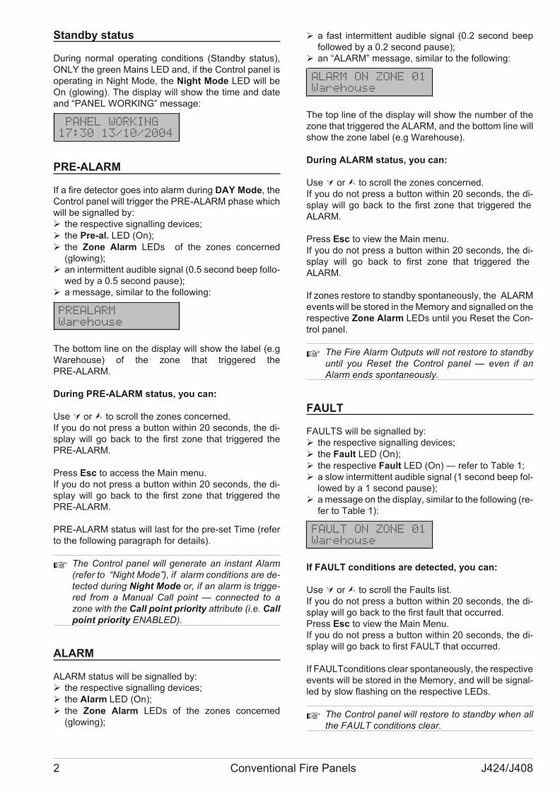
Standby status
Du ring nor mal ope ra ting con di tions (Standby sta tus),ONLY the gre en Ma ins LED and, if the Con trol pa nel isope ra ting in Night Mode, the Night Mode LED will beOn (glo wing). The di splay will show the time and dateand “PANEL WORKING” mes sa ge:
PANEL WORKING
17:30 13/10/2004
PRE-ALARM
If a fire de tec tor goes into alarm du ring DAY Mode, theCon trol pa nel will trig ger the PRE-ALARM pha se whichwill be si gnal led by:Ø the re spec ti ve si gnal ling de vi ces;Ø the Pre-al. LED (On);Ø the Zone Alarm LEDs of the zo nes con cer ned
(glowing);Ø an in ter mit tent au di ble si gnal (0.5 se cond beep fol lo -
wed by a 0.5 se cond pa u se);Ø a mes sa ge, si mi lar to the fol lo wing:
PREALARM
Warehouse
The bot tom line on the di splay will show the la bel (e.gWa re ho u se) of the zone that trig ge red thePRE-ALARM.
Du ring PRE-ALARM sta tus, you can:
Use Ú or Ù to scroll the zo nes con cer ned. If you do not press a but ton wit hin 20 se conds, the di -splay will go back to the first zone that trig ge red thePRE-ALARM.
Press Esc to ac cess the Main menu.If you do not press a but ton wit hin 20 se conds, the di -splay will go back to the first zone that trig ge red thePRE-ALARM.
PRE-ALARM sta tus will last for the pre-set Time (re ferto the fol lo wing pa ra graph for de ta ils).
+ The Con trol pa nel will ge ne ra te an in stant Alarm(re fer to “Night Mode”), if alarm con di tions are de -tec ted du ring Night Mode or, if an alarm is trig ge -red from a Ma nual Call po int — con nec ted to azone with the Call po int prio rity at tri bu te (i.e. Callpo int prio rity ENABLED).
ALARM
ALARM sta tus will be si gnal led by:Ø the re spec ti ve si gnal ling de vi ces;Ø the Alarm LED (On);Ø the Zone Alarm LEDs of the zo nes con cer ned
(glowing);
Ø a fast in ter mit tent au di ble si gnal (0.2 se cond beepfol lo wed by a 0.2 se cond pa u se);
Ø an “ALARM” mes sa ge, si mi lar to the fol lo wing:
ALARM ON ZONE 01
Warehouse
The top line of the di splay will show the num ber of thezone that trig ge red the ALARM, and the bot tom line willshow the zone la bel (e.g Wa re ho u se).
Du ring ALARM sta tus, you can:
Use Ú or Ù to scroll the zo nes con cer ned. If you do not press a but ton wit hin 20 se conds, the di -splay will go back to the first zone that trig ge red the ALARM.
Press Esc to view the Main menu.If you do not press a but ton wit hin 20 se conds, the di -splay will go back to first zone that trig ge red the ALARM.
If zo nes re sto re to standby spon ta ne o usly, the ALARMevents will be sto red in the Me mory and si gnal led on the re spec ti ve Zone Alarm LEDs un til you Re set the Con -trol pa nel.
+ The Fire Alarm Out puts will not re sto re to standbyun til you Re set the Con trol pa nel — even if anAlarm ends spon ta ne o usly.
FAULT
FAULTS will be si gnal led by:Ø the re spec ti ve si gnal ling de vi ces;Ø the Fa ult LED (On);Ø the re spec ti ve Fa ult LED (On) — re fer to Ta ble 1;Ø a slow in ter mit tent au di ble si gnal (1 se cond beep fol -
lo wed by a 1 se cond pa u se);Ø a mes sa ge on the di splay, si mi lar to the fol lo wing (re -
fer to Ta ble 1):
FAULT ON ZONE 01
Warehouse
If FAULT con di tions are de tec ted, you can:
Use Ú or Ù to scroll the Fa ults list.If you do not press a but ton wit hin 20 se conds, the di -splay will go back to the first fa ult that oc cur red.Press Esc to view the Main Menu.If you do not press a but ton wit hin 20 se conds, the di -splay will go back to first FAULT that oc cur red.
If FAULTcon di tions cle ar spon ta ne o usly, the re spec ti ve events will be sto red in the Me mory, and will be si gnal -led by slow fla shing on the re spec ti ve LEDs.
+ The Con trol pa nel will re sto re to standby when allthe FAULT con di tions cle ar.
2 Conventional Fire Panels J424/J408
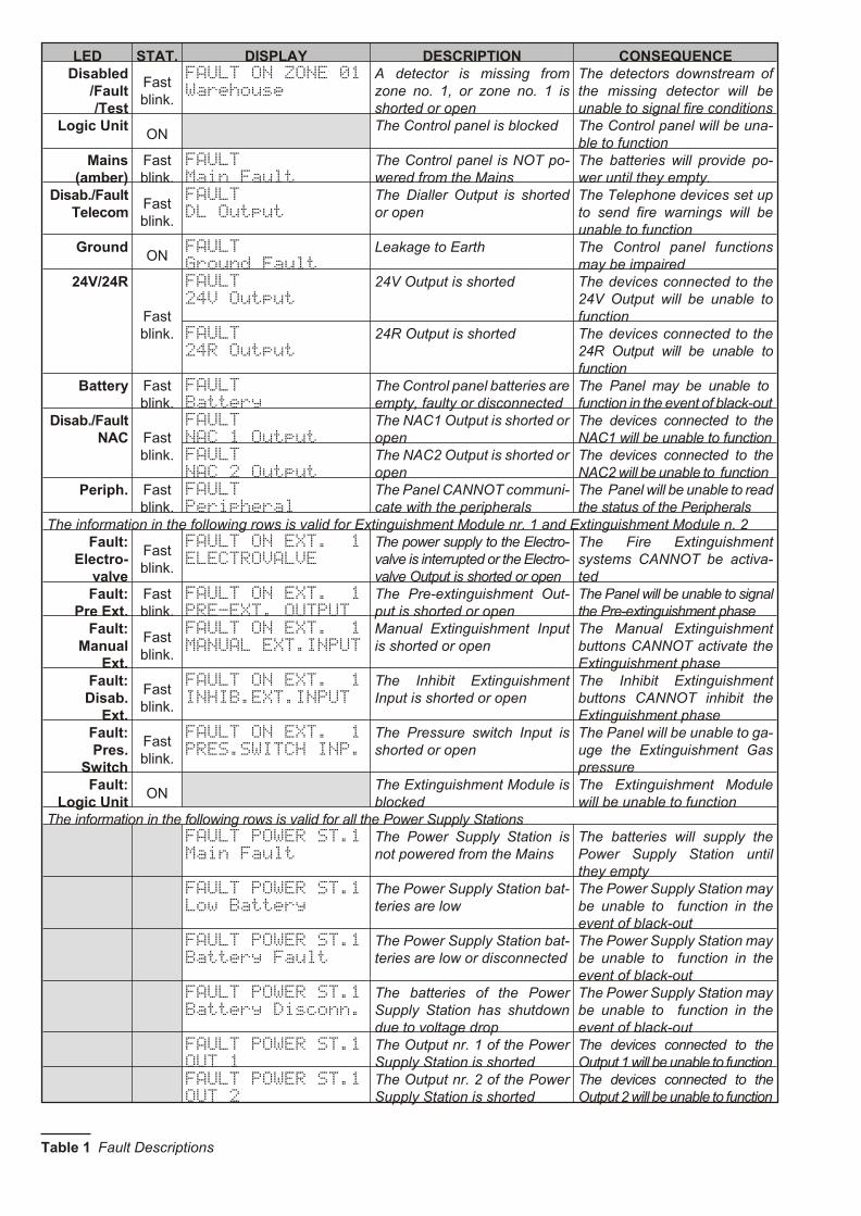
LED STAT. DISPLAY DESCRIPTION CONSEQUENCEDisabled
/Fault/Test
Fastblink.
FAULT ON ZONE 01
Warehouse
A de tec tor is mis sing fromzone no. 1, or zo ne no. 1 isshor ted or open
The de tec tors downstre am ofthe mis sing de tec tor will beuna ble to si gnal fire conditions
Logic UnitON
The Con trol pa nel is blocked The Con trol pa nel will be una -ble to function
Mains(amber)
Fastblink.
FAULT
Main Fault
The Con trol pa nel is NOT po -we red from the Ma ins
The bat te ries will pro vi de po -wer un til they empty.
Disab./Fault Telecom
Fastblink.
FAULT
DL Output
The Dial ler Out put is shor tedor open
The Te lep ho ne de vi ces set upto send fire war nings will beuna ble to fun ction
GroundON
FAULT
Ground Fault
Le a ka ge to Earth The Con trol pa nel fun ctio nsmay be im pa i red
24V/24R
Fastblink.
FAULT
24V Output
24V Out put is shor ted The de vi ces con nec ted to the24V Out put will be una ble tofun ction
FAULT
24R Output
24R Out put is shor ted The de vi ces con nec ted to the24R Out put will be una ble tofun ction
Battery Fastblink.
FAULT
Battery
The Con trol pa nel bat te ries are empty, fa ulty or di scon nec ted
The Pa nel may be una ble to fun ction in the event of black-out
Disab./Fault NAC Fast
blink.
FAULT
NAC 1 Output
The NAC1 Out put is shor ted or open
The de vi ces con nec ted to theNAC1 will be una ble to fun ction
FAULT
NAC 2 Output
The NAC2 Out put is shor ted or open
The de vi ces con nec ted to theNAC2 will be una ble to fun ction
Periph. Fastblink.
FAULT
Peripheral
The Pa nel CANNOT com mu ni -ca te with the pe rip he rals
The Pa nel will be una ble to read the sta tus of the Pe rip he rals
The in for ma tion in the fol lo wing rows is va lid for Extin gui shment Mo du le nr. 1 and Extin gui shment Mo du le n. 2Fault:
Electro-valve
Fastblink.
FAULT ON EXT. 1
ELECTROVALVE
The po wer supply to the Elec tro -val ve is in ter rup ted or the Elec tro -val ve Out put is shor ted or open
The Fire Extin gui shmentsystems CANNOT be ac ti va -ted
Fault:Pre Ext.
Fastblink.
FAULT ON EXT. 1
PRE-EXT. OUTPUT
The Pre-ex tin gui shment Out -put is shor ted or open
The Pa nel will be una ble to si gnalthe Pre-ex tin gui shment pha se
Fault:Manual
Ext.
Fastblink.
FAULT ON EXT. 1
MANUAL EXT.INPUT
Ma nual Ex tin gui shment Inputis shor ted or open
The Ma nual Extin gui shmentbut tons CANNOT ac ti va te theExtin gui shment pha se
Fault:Disab.
Ext.
Fastblink.
FAULT ON EXT. 1
INHIB.EXT.INPUT
The Inhi bit Extin gui shmentInput is shor ted or open
The Inhi bit Extin gui shmentbut tons CANNOT inhi bit theExtin gui shment pha se
Fault:Pres.
Switch
Fastblink.
FAULT ON EXT. 1
PRES.SWITCH INP.
The Pres su re switch Input isshor ted or open
The Pa nel will be una ble to ga -u ge the Extin gui shment Gaspres su re
Fault:Logic Unit
ONThe Extin gui shment Mo du le isblocked
The Extin gui shment Mo du lewill be una ble to fun ction
The in for ma tion in the fol lo wing rows is va lid for all the Po wer Supply Sta tionsFAULT POWER ST.1
Main Fault
The Po wer Supply Sta tion isnot po we red from the Ma ins
The bat te ries will supply thePo wer Supply Sta tion un tilthey empty
FAULT POWER ST.1
Low Battery
The Po wer Supply Sta tion bat -te ries are low
The Po wer Supply Sta tion may be una ble to fun ction in theevent of black-out
FAULT POWER ST.1
Battery Fault
The Po wer Supply Sta tion bat -te ries are low or disconnected
The Po wer Supply Sta tion may be una ble to fun ction in theevent of black-out
FAULT POWER ST.1
Battery Disconn.
The bat te ries of the Po werSupply Sta tion has shut downdue to vol ta ge drop
The Po wer Supply Sta tion may be una ble to fun ction in theevent of black-out
FAULT POWER ST.1
OUT 1
The Out put nr. 1 of the Po werSupply Sta tion is shor ted
The de vi ces con nec ted to theOut put 1 will be una ble to fun ction
FAULT POWER ST.1
OUT 2
The Out put nr. 2 of the Po werSupply Sta tion is shor ted
The de vi ces con nec ted to theOut put 2 will be una ble to fun ction
Ta ble 1 Fa ult De scri ptions
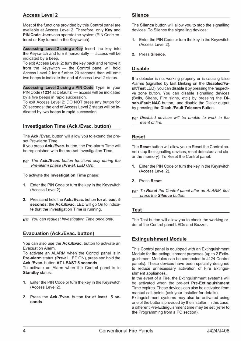
Access Level 2
Most of the fun ctions pro vi ded by this Con trol pa nel areava i la ble at Access Le vel 2. The re fo re, only Key andPIN Code Users can ope ra te the system (PIN Code en -te red or Key tur ned in the Key switch).
Accessing Level 2 using a Key Insert the key intothe Key switch and turn it ho ri zon tally — ac cess will bein di ca ted by a beep.To exit Access Le vel 2: turn the key back and re mo ve it from the Key switch — the Con trol pa nel will holdAccess Le vel 2 for a fur ther 20 se conds then will emittwo be eps to in di ca te the end of Access Le vel 2 sta tus.
Accessing Level 2 using a PIN Code Type in yourPIN Code (1234 at De fa ult): — ac cess will be in di ca ted by a five be eps in ra pid suc ces sion.To exit Access Le vel 2: DO NOT press any but ton for 20 se conds: the end of Access Le vel 2 sta tus will be in -di ca ted by two be eps in ra pid suc ces sion.
Investigation Time (Ack./Evac. button)
The Ack./Evac. but ton will al low you to ex tend the pre -set Pre-alarm Time. If you press Ack./Evac. but ton, the Pre-alarm Time willbe re ple ni shed with the pre-set Inve sti ga tion Time.
+ The Ack./Evac. but ton fun ctions only du ring thePre-alarm pha se (Pre-al. LED ON).
To ac ti va te the Inve sti ga tion Time pha se:
1. Enter the PIN Code or turn the key in the Key switch(Access Le vel 2).
2. Press and hold the Ack./Evac. but ton for at le ast 5 se conds: the Ack./Evac. LED will go On to in di ca -te that the Inve sti ga tion Time is run ning.
+ You can re quest Inve sti ga tion Time once only.
Evacuation (Ack./Evac. button)
You can also use the Ack./Evac. but ton to ac ti va te anEva cua tion Alarm.To ac ti va te an ALARM when the Con trol pa nel is inPre-alarm sta tus (Pre-al. LED ON), press and hold the Ack./Evac. but ton AT LEAST 5 se conds. To ac ti va te an Alarm when the Con trol pa nel is inStandby sta tus:
1. Enter the PIN Code or turn the key in the Key switch(Access Le vel 2).
2. Press the Ack./Evac. but ton for at le ast 5 se -conds.
Silence
The Si len ce but ton will al low you to stop the si gnal lingde vi ces. To Si len ce the si gnal ling de vi ces:
1. Enter the PIN Code or turn the key in the Key switch(Access Le vel 2).
2. Press Si len ce.
Disable
If a de tec tor is not wor king pro perly or is ca u sing fal seAlarms (si gnal led by fast blin king on the Di sa bled/Fa -ult/Test LED), you can di sa ble it by pres sing the re spec ti -ve zone but ton. You can di sa ble si gnal ling de vi ces(Bells, Si rens, Fire signs, etc.) by pres sing the Di -sab./Fa ult NAC but ton, and di sa ble the Dial ler out putby pres sing the Di sab./Fa ult Te le com But ton.
+ Di sa bled de vi ces will be una ble to work in theevent of fire.
Reset
The Re set but ton will al low you to Re set the Con trol pa -nel (stop the si gnal ling de vi ces, re set de tec tors and cle -ar the me mory). To Re set the Con trol pa nel:
1. Enter the PIN Code or turn the key in the Key switch(Access Le vel 2).
2. Press Re set.
+ To Re set the Con trol pa nel af ter an ALARM, firstpress the Si len ce but ton.
Test
The Test but ton will al low you to check the wor king or -der of the Con trol pa nel LEDs and Buz zer.
Extinguishment Module
This Con trol pa nel is equip ped with an Extin gui shmentMo du le for fire ex tin gui shment pur po ses (up to 2 Extin -gui shment Mo du les can be con nec ted to J424 Con trolpa nels). The se de vi ces have been spe cially de si gnedto re du ce un ne ces sary ac ti va tion of Fire Extin gui -shment ap plian ces.In the event of a Fire, the Extin gui shment systems willbe ac ti va ted when the pre-set Pre-Extin gui shmentTime ex pi res. The se de vi ces can also be ac ti va ted from ma nual call-po ints (ask your Instal ler for de ta ils).Extin gui shment systems may also be ac ti va ted usingone of the but tons pro vi ded by the in stal ler. In this case,a dif fe rent Pre-Extin gui shment time may be set (re fer tothe Pro gram ming from a PC section).
4 Conventional Fire Panels J424/J408

n Pre-extinguishment PhaseIf the pro gram med ex tin gui shment con di tions oc cur(pro gram med by your Instal ler), the Extin gui shmentMo du le will ge ne ra te the Pre-ex tin gui shment pha sewhich will be si gnal led by:Ø the re spec ti ve si gnal ling de vi ces;Ø the ON Pre Ext. LED (On).Ø buz zer.
The Extin gui shment Mo du le will ac ti va te the Fire Extin -gui shment systems when the Pre-ex tin gui shment Timeex pi res.The Pre-ex tin gui shment pha se will al low you to checkwhet her use of Fire Extin gui shment systems, and Eva -cua tion of the pre mi ses are re ally ne ces sary.
You can end this pha se by pres sing:Ø any “Stop Extin gui shment” but ton (set up by your
Instal ler).In this case, the Pre-Extin gui shment Time will NOT bestop ped by the Con trol pa nel. When the time has elap -sed, no ex tin gui shment will oc cur un less the IE Input isre sto red to stanby.
+ The Di sa ble Extin guish. but ton can be used du -ring Access Le vel 2 only.
n Extinguishment PhaseThe Extin gui shment Mo du le will ac ti va te the Fire Extin -gui shment systems when the Pre-ex tin gui shment Pha -se ex pi res.
The Extin gui shment Pha se will be si gnal led by.Ø the ON Elec tro val ve LED (On).Ø the de vi ces pro vi ded by the in stal ler.Ø buz zer.
The AV ACTIVATED event, and the re spec ti ve de ta ilswill be re cor ded in the log ger (EXTING.MODULE 1 orEXTING.MODULE 2).The Extin gui shment Pha se will run for the pre-set Extin gui -shment Time or un til the Con trol pa nel Re sets.
n Manual ExtinguishmentThe Extin gui shment Mo du le can be ac ti va ted from ma -nual call-po ints (ask your Instal ler for de ta ils).Ma nual ac ti va tion of the Extin gui shment Mo du le is si -gnal led by:Ø the ON Ma nual Ext. LED (On);Ø a mes sa ge on the di splay si mi lar to the fol lo wing:
EXTING.MODULE.1
MANUAL ACTIVATE
Ø buz zer.
+ If you ac ti va te the Extin gui shment Mo du le ma -nually, the Con trol pa nel will ge ne ra te an Alarm.
+ Pre-Extin gui shment and Extin gui shment will NOTbe car ried out by the Con trol pa nel in the event of afa ult on the PR Out put or the IE Out put.
n Disable Extinguish. buttonThis but ton will al low you to in hi bit the Fire Extin gui -shment systems.
+ The Di sa ble Extin guish. but ton can be used du -ring Access Le vel 2 only.
This ope ra tion will be si gnal led by:Ø the Di sa ble Extin guish. LED (On);Ø the Di sab. LED (On).
The OUTS BYPASS event, and re spec ti ve de ta ils willbe re cor ded in the log ger (EXTING.MODULE 1 orEXTING.MODULE 2).
If you di sa ble the Extin gui shment Mo du le du ringStandby sta tus, it will be una ble to ope ra te in the eventof an Alarm.
n Disable Manual Extinguish. buttonThis but ton will al low you to Di sa ble/Ena ble ma nual ac -ti va tion of the Extin gui shment Mo du le.
+ The Di sa ble Ma nual Extin guish. but ton can beused du ring Access Le vel 2 only.
This ope ra tion will be si gnal led by:Ø the Di sa ble Ma nual Extin guish. LED (On);Ø the Di sab. LED (On).
n Disable Automatic ExtinguishmentThis but ton will al low you to Di sa ble/Ena ble the ac ti va -tion of ex tin gui shment, via the de tec tors pro vi ded by the in stal ler.
+ The Di sa ble Automatic Extin guish. but ton canbe used du ring Access Le vel 2 only.
This ope ra tion will be si gnal led by:Ø the Di sa ble Au to ma tic Extin guish. LED (On);Ø the Di sab. LED (On).
USER’S INSTRUCTIONS 5
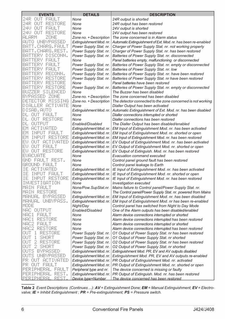
6 Conventional Fire Panels J424/J408
EVENTS DETAILS DESCRIPTION24R OUT FAULT None 24R out put is shor ted24R OUT RESTORE None 24R out put has been re sto red24V OUT FAULT None 24V out put is shor ted24V OUT RESTORE None 24V out put has been re sto redALARM ZONE Zone no. + De scrip tion The zone con cer ned is in Alarm sta tusAUTO UNBYPASSED Extin gui shment Mod. nr. Au to ma tic Extin gui shment of Ext. Mod. nr. has been re-ena bledBATT.CHARG.FAULT Po wer Supply Stat. nr. Char ger of Po wer Supply Stat. nr. not wor king pro perlyBATT.CHARG.REST. Po wer Supply Stat. nr. Char ger of Po wer Supply Stat. nr. has been re sto redBATTERY DISCONN. Po wer Supply Stat. nr. Bat te ries of Po wer Supply Stat. nr. di scon nec tedBATTERY FAULT None Pa nel bat te ries empty, mal fun ctio ning or di scon nec ted BATTERY FAULT Po wer Supply Stat. nr. Bat te ries of Po wer Supply Stat. nr. empty or di scon nec tedBATTERY FAULT Po wer Supply Stat. nr. Bat te ries of Po wer Supply Stat. nr. lowBATTERY RECONN. Po wer Supply Stat. nr. Bat te ries of Po wer Supply Stat. nr. have been re sto redBATTERY RESTORE Po wer Supply Stat. nr. Bat te ries of Po wer Supply Stat. nr have been re sto redBATTERY RESTORE None Pa nel bat te ries have been re sto redBATTERY RESTORE Po wer Supply Stat. nr. Bat te ries of Po wer Supply Stat. nr. empty or di scon nec tedBUZZER SILENCED None The Buz zer has been di sa bledBYPASSED ZONE Zone no. + De scrip tion The zone con cer ned has been di sa bledDETECTOR MISSING Zone no. + De scrip tion The de tec tor con nec ted to the zone con cer ned is not workingDIALLER ACTIVATE None Dial ler Out put has been activatedDISAB.AUTO Extin gui shment Mod. nr. Au to ma tic Extin gui shment of Ext. Mod. nr. has been di sa bledDL OUT FAULT None Dial ler con nec tions in ter rup ted or shor tedDL OUT RESTORE None Dial ler con nec tions has been re sto redDL OUTPUT Ena bled/Disabled The Dial ler Out put has been di sa bled/enabledEM ACTIVATED Extin gui shment Mod. nr. EM Input of Extin gui shment Mod. nr. has been ac ti va tedEM INPUT FAULT Extin gui shment Mod. nr. EM Input of Extin gui shment Mod. nr. shor ted or openEM INPUT RESTORE Extin gui shment Mod. nr. EM Input of Extin gui shment Mod. nr. has been re sto redEV OUT ACTIVATED Extin gui shment Mod. nr. EV Out put of Extin gui shment Mod. nr. has been ac ti va tedEV OUT FAULT Extin gui shment Mod. nr. EV Out put of Extin gui shment Mod. nr. shor ted or openEV OUT RESTORE Extin gui shment Mod. nr. EV Out put of Extin guish. Mod. nr. has been re sto redEVACUATE None Eva cua tion com mand exe cu tedGND FAULT REST. None Con trol pa nel gro und fa ult has been re sto redGROUND FAULT None Con trol pa nel le a ka ge to EarthIE ACTIVATED Extin gui shment Mod. nr. IE Input of Extin gui shment Mod. nr. has been activatedIE INPUT FAULT Extin gui shment Mod. nr. IE Input of Extin gui shment Mod. nr. shor ted or openIE INPUT RESTORE Extin gui shment Mod. nr. IE Input of Extin gui shment Mod. nr. has been re sto redINVESTIGATION None Inve sti ga tion executedMAIN FAULT None/Pow.SupStat.nr. Ma ins fa i lu re to Con trol pa nel/Po wer Supply Stat. nr.MAIN RESTORE None The Con trol pa nel/Po wer Supply Stat. nr. po we red from MainsMANUAL BYPASSED Extin gui shment Mod. nr. EM Input of Extin gui shment Mod. nr. has been di sa bledMANUAL UNBYPASS. Extin gui shment Mod. nr. EM Input of Extin gui shment Mod. nr has been re-ena bledMODE Night/Day Con trol pa nel has swit ched from Night to Day ModeNAC OUTPUT Ena bled/Di sa bled One of the Alarm out puts has been di sa bled/ena bledNAC1 FAULT None Alarm de vi ce con nec tions in ter rup ted or shor tedNAC1 RESTORE None Alarm de vi ce con nec tions in ter rup ted has been re sto redNAC2 FAULT None Alarm de vi ce con nec tions in ter rup ted or shor tedNAC2 RESTORE None Alarm de vi ce con nec tions in ter rup ted has been re sto redOUT 1 RESTORE Po wer Supply Stat. nr. O1 Out put of Po wer Supply Stat. nr has been re sto redOUT 1 SHORT Po wer Supply Stat. nr. O1 Out put of Po wer Supply Stat. nr shortedOUT 2 RESTORE Po wer Supply Stat. nr. O2 Out put of Po wer Supply Stat. nr has been re sto redOUT 2 SHORT Po wer Supply Stat. nr. O2 Out put of Po wer Supply Stat. nr shor tedOUTS BYPASSED Extin gui shment Mod. nr. Extin gui shment Mod. PR, EV and AV out puts di sa bledOUTS UNBYPASSED Extin gui shment Mod. nr. Extin gui shment Mod. PR, EV and AV out puts re-ena bledPR OUT ACTIVATED Extin gui shment Mod. nr. PR Out put of Extin gui shment Mod. nr. ac ti va tedPR OUT FAULT Extin gui shment Mod. nr. PR Out put of Extin gui shment Mod. nr. shor ted or openPERIPHERAL FAULT Pe rip heral type and nr. The de vi ce con cer ned is mis sing or fa ultyPERIPHERAL REST. Extin gui shment Mod. nr. PR Out put of Extin guish. Mod. nr. has been re sto redPERIPHERAL REST. De vi ce type+Number The de vi ce con cer ned has been re sto red
Ta bl e 2 Event De scrip tions (Con ti nu es ...): AV = Extin gui shment Done; EM = Ma nual Extin gui shment; EV = Elec tro -val ve; IE = Inhi bit Extin gui shment ; PR = Pre-ex tin gui shment; PS = Pres su re switch.
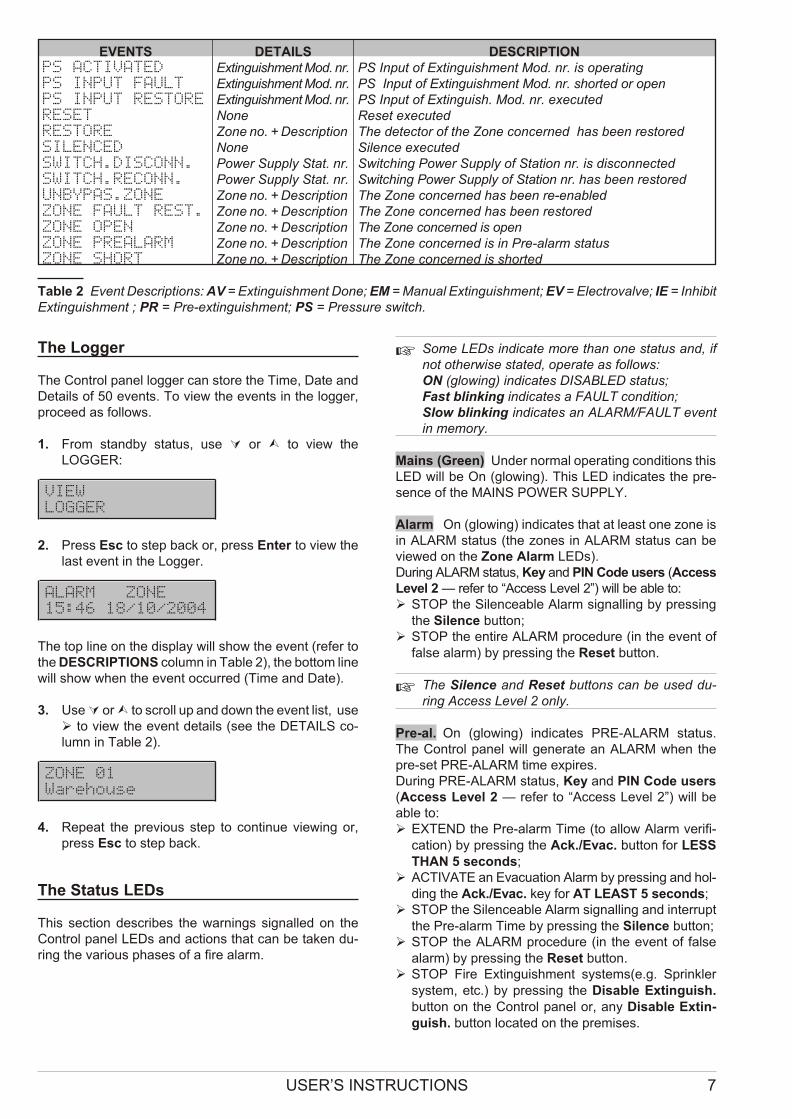
The Logger
The Con trol pa nel log ger can sto re the Time, Date andDe ta ils of 50 events. To view the events in the log ger,pro ce ed as fol lows.
1. From standby sta tus, use Ú or Ù to view theLOGGER:
VIEW
LOGGER
2. Press Esc to step back or, press Enter to view thelast event in the Log ger.
ALARM ZONE
15:46 18/10/2004
The top line on the di splay will show the event (re fer tothe DESCRIPTIONS co lumn in Ta ble 2), the bot tom line will show when the event oc cur red (Time and Date).
3. Use Ú or Ù to scroll up and down the event list, use Ø to view the event de ta ils (see the DETAILS co -lumn in Ta ble 2).
ZONE 01
Warehouse
4. Re pe at the pre vio us step to con ti nue vie wing or,press Esc to step back.
The Status LEDs
This sec tion de scri bes the war nings si gnal led on theCon trol pa nel LEDs and ac tions that can be ta ken du -ring the va rio us pha ses of a fire alarm.
+ Some LEDs in di ca te more than one sta tus and, ifnot ot her wi se sta ted, ope ra te as fol lows: ON (glo wing) in di ca tes DISABLED sta tus; Fast blin king in di ca tes a FAULT con di tion; Slow blin king in di ca tes an ALARM/FAULT eventin me mory.
Mains (Green) Under nor mal ope ra ting con di tions this LED will be On (glo wing). This LED in di ca tes the pre -sen ce of the MAINS POWER SUPPLY.
Alarm On (glo wing) in di ca tes that at le ast one zone isin ALARM sta tus (the zo nes in ALARM sta tus can bevie wed on the Zone Alarm LEDs). Du ring ALARM sta tus, Key and PIN Code users (AccessLe vel 2 — re fer to “Access Le vel 2”) will be able to:Ø STOP the Si len ce a ble Alarm si gnal ling by pres sing
the Si len ce but ton;Ø STOP the en ti re ALARM pro ce du re (in the event of
fal se alarm) by pres sing the Re set but ton.
+ The Si len ce and Re set but tons can be used du -ring Access Le vel 2 only.
Pre-al. On (glo wing) in di ca tes PRE-ALARM sta tus.The Con trol pa nel will ge ne ra te an ALARM when thepre-set PRE-ALARM time ex pi res. Du ring PRE-ALARM sta tus, Key and PIN Code users(Access Le vel 2 — re fer to “Access Le vel 2”) will beable to:Ø EXTEND the Pre-alarm Time (to al low Alarm ve ri fi -
ca tion) by pres sing the Ack./Evac. but ton for LESSTHAN 5 se conds;
Ø ACTIVATE an Eva cua tion Alarm by pres sing and hol -ding the Ack./Evac. key for AT LEAST 5 se conds;
Ø STOP the Si len ce a ble Alarm si gnal ling and in ter ruptthe Pre-alarm Time by pres sing the Si len ce but ton;
Ø STOP the ALARM pro ce du re (in the event of fal sealarm) by pres sing the Re set but ton.
Ø STOP Fire Extin gui shment systems(e.g. Sprin klersystem, etc.) by pres sing the Di sa ble Extin guish.but ton on the Con trol pa nel or, any Di sa ble Extin -guish. but ton lo ca ted on the pre mi ses.
USER’S INSTRUCTIONS 7
EVENTS DETAILS DESCRIPTIONPS ACTIVATED Extin gui shment Mod. nr. PS Input of Extin gui shment Mod. nr. is operatingPS INPUT FAULT Extin gui shment Mod. nr. PS Input of Extin gui shment Mod. nr. shor ted or openPS INPUT RESTORE Extin gui shment Mod. nr. PS Input of Extin guish. Mod. nr. exe cu tedRESET None Re set exe cu tedRESTORE Zone no. + De scrip tion The de tec tor of the Zone con cer ned has been re sto redSILENCED None Si len ce executedSWITCH.DISCONN. Po wer Supply Stat. nr. Swit ching Po wer Supply of Station nr. is di scon nec tedSWITCH.RECONN. Po wer Supply Stat. nr. Swit ching Po wer Supply of Sta tion nr. has been re sto redUNBYPAS.ZONE Zone no. + De scrip tion The Zone con cer ned has been re-ena bledZONE FAULT REST. Zone no. + De scrip tion The Zone con cer ned has been re sto redZONE OPEN Zone no. + De scrip tion The Zone con cer ned is openZONE PREALARM Zone no. + De scrip tion The Zone con cer ned is in Pre-alarm sta tusZONE SHORT Zone no. + De scrip tion The Zone con cer ned is shorted
Ta ble 2 Event De scrip tions: AV = Extin gui shment Done; EM = Ma nual Extin gui shment; EV = Electro val ve; IE = Inhi bit Extin gui shment ; PR = Pre-ex tin gui shment; PS = Pres su re switch.
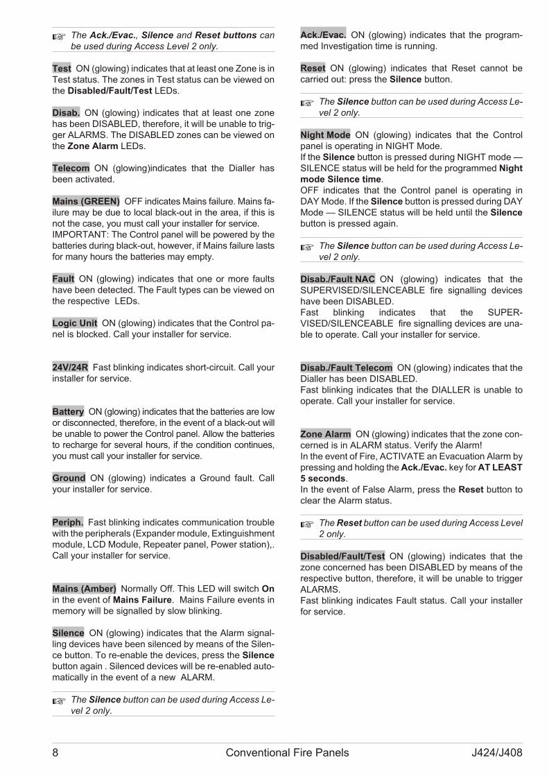
+ The Ack./Evac., Si len ce and Re set but tons canbe used du ring Access Le vel 2 only.
Test ON (glo wing) in di ca tes that at le ast one Zone is inTest sta tus. The zo nes in Test sta tus can be vie wed onthe Di sa bled/Fa ult/Test LEDs.
Disab. ON (glo wing) in di ca tes that at le ast one zonehas been DISABLED, the re fo re, it will be una ble to trig -ger ALARMS. The DISABLED zo nes can be vie wed onthe Zone Alarm LEDs.
Telecom ON (glo wing)in di ca tes that the Dial ler hasbeen ac ti va ted.
Mains (GREEN) OFF in di ca tes Ma ins fa i lu re. Ma ins fa -i lu re may be due to lo cal black-out in the area, if this isnot the case, you must call your in stal ler for ser vi ce.IMPORTANT: The Con trol pa nel will be po we red by thebat te ries du ring black-out, ho we ver, if Ma ins fa i lu re lastsfor many ho urs the bat te ries may empty.
Fault ON (glo wing) in di ca tes that one or more fa ultshave been de tec ted. The Fa ult types can be vie wed onthe re spec ti ve LEDs.
Logic Unit ON (glo wing) in di ca tes that the Con trol pa -nel is bloc ked. Call your in stal ler for ser vi ce.
24V/24R Fast blin king in di ca tes short-cir cu it. Call yourin stal ler for ser vi ce.
Battery ON (glo wing) in di ca tes that the bat te ries are lowor di scon nec ted, the re fo re, in the event of a black-out willbe una ble to po wer the Con trol pa nel. Allow the bat te riesto re char ge for se ve ral ho urs, if the con di tion con ti nu es,you must call your in stal ler for ser vi ce.
Ground ON (glo wing) in di ca tes a Gro und fa ult. Callyour in stal ler for ser vi ce.
Periph. Fast blin king in di ca tes com mu ni ca tion tro u blewith the pe rip he rals (Expan der mo du le, Extin gui shment mo du le, LCD Mo du le, Re pe a ter pa nel, Po wer sta tion),.Call your in stal ler for ser vi ce.
Mains (Amber) Nor mally Off. This LED will switch Onin the event of Ma ins Fa i lu re. Ma ins Fa i lu re events inme mory will be si gnal led by slow blin king.
Silence ON (glo wing) in di ca tes that the Alarm si gnal -ling de vi ces have been si len ced by me ans of the Si len -ce but ton. To re-ena ble the de vi ces, press the Si len cebut ton aga in . Si len ced de vi ces will be re-ena bled au to -ma ti cally in the event of a new ALARM.
+ The Si len ce but ton can be used du ring Access Le -vel 2 only.
Ack./Evac. ON (glo wing) in di ca tes that the pro gram -med Inve sti ga tion time is run ning.
Reset ON (glo wing) in di ca tes that Re set can not becar ried out: press the Si len ce but ton.
+ The Si len ce but ton can be used du ring Access Le -vel 2 only.
Night Mode ON (glo wing) in di ca tes that the Con trolpa nel is ope ra ting in NIGHT Mode.If the Si len ce but ton is pres sed du ring NIGHT mode —SILENCE sta tus will be held for the pro gram med Nightmode Si len ce time.OFF in di ca tes that the Con trol pa nel is ope ra ting inDAY Mode. If the Si len ce but ton is pres sed du ring DAYMode — SILENCE sta tus will be held un til the Si len cebut ton is pres sed aga in.
+ The Si len ce but ton can be used du ring Access Le -vel 2 only.
Disab./Fault NAC ON (glo wing) in di ca tes that theSUPER VISED/SILENCEABLE fire si gnal ling de vi ceshave been DISABLED.Fast blin king in di ca tes that the SUPER -VISED/SILENCEABLE fire si gnal ling de vi ces are una -ble to ope ra te. Call your in stal ler for ser vi ce.
Disab./Fault Telecom ON (glo wing) in di ca tes that theDial ler has been DISABLED.Fast blin king in di ca tes that the DIALLER is una ble toope ra te. Call your in stal ler for ser vi ce.
Zone Alarm ON (glo wing) in di ca tes that the zone con -cer ned is in ALARM sta tus. Ve rify the Alarm!In the event of Fire, ACTIVATE an Eva cua tion Alarm bypres sing and hol ding the Ack./Evac. key for AT LEAST 5 se conds.In the event of Fal se Alarm, press the Re set but ton tocle ar the Alarm sta tus.
+ The Re set but ton can be used du ring Access Le vel 2 only.
Disabled/Fault/Test ON (glo wing) in di ca tes that thezone con cer ned has been DISABLED by me ans of there spec ti ve but ton, the re fo re, it will be una ble to trig gerALARMS.Fast blin king in di ca tes Fa ult sta tus. Call your in stal lerfor ser vi ce.
8 Conventional Fire Panels J424/J408
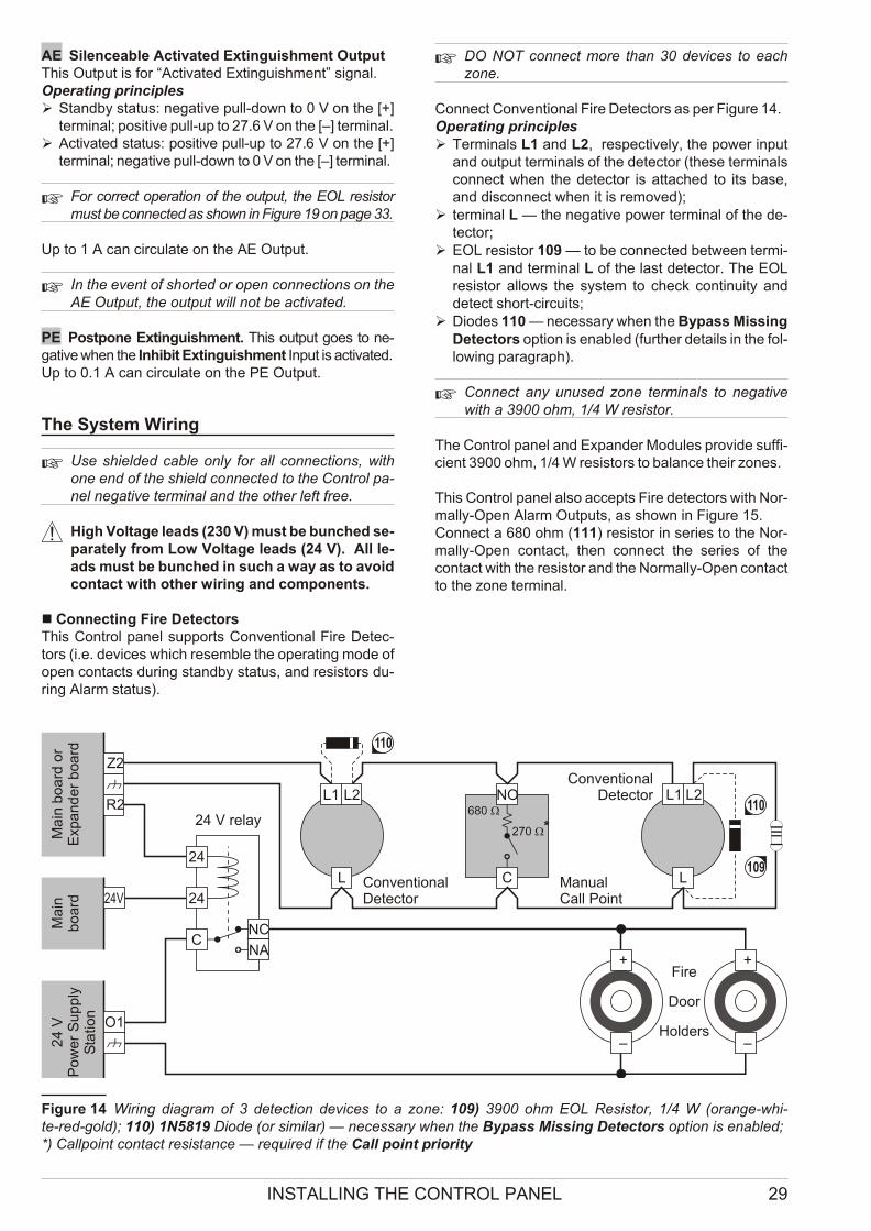
AE Si len ce a ble Acti va ted Extin gui shment Out putThis Out put is for “Acti va ted Extin gui shment” si gnal.Ope ra ting prin ci plesØ Standby sta tus: ne ga ti ve pull-down to 0 V on the [+]
ter mi nal; po si ti ve pull-up to 27.6 V on the [–] ter mi nal.Ø Acti va ted sta tus: po si ti ve pull-up to 27.6 V on the [+]
ter mi nal; ne ga ti ve pull-down to 0 V on the [–] ter mi nal.
+ For cor rect ope ra tion of the out put, the EOL re si stormust be con nec ted as shown in Fi gu re 19 on page 33.
Up to 1 A can cir cu la te on the AE Out put.
+ In the event of shor ted or open con nec tions on theAE Out put, the out put will not be ac ti va ted.
PE Po stpo ne Extin gui shment. This out put goes to ne -ga ti ve when the Inhi bit Extin gui shment Input is ac ti va ted.Up to 0.1 A can cir cu la te on the PE Out put.
The System Wiring
+ Use shiel ded ca ble only for all con nec tions, withone end of the shield con nec ted to the Con trol pa -nel ne ga ti ve ter mi nal and the ot her left free.
! High Vol ta ge le ads (230 V) must be bun ched se -pa ra tely from Low Vol ta ge le ads (24 V). All le -ads must be bun ched in such a way as to avo idcon tact with ot her wi ring and com po nents.
n Connecting Fire DetectorsThis Con trol pa nel sup ports Con ven tio nal Fire De tec -tors (i.e. de vi ces which re sem ble the ope ra ting mode ofopen con tacts du ring standby sta tus, and re si stors du -ring Alarm sta tus).
+ DO NOT con nect more than 30 de vi ces to eachzone.
Con nect Con ven tio nal Fire De tec tors as per Fi gu re 14.Ope ra ting prin ci plesØ Ter mi nals L1 and L2, re spec ti vely, the po wer in put
and out put ter mi nals of the de tec tor (the se ter mi nalscon nect when the de tec tor is at ta ched to its base,and di scon nect when it is re mo ved);
Ø ter mi nal L — the ne ga ti ve po wer ter mi nal of the de -tec tor;
Ø EOL re si stor 109 — to be con nec ted bet we en ter mi -nal L1 and ter mi nal L of the last de tec tor. The EOLre si stor al lows the system to check con ti nu ity andde tect short-cir cu its;
Ø Dio des 110 — ne ces sary when the Bypass Mis sing De tec tors op tion is ena bled (fur ther de ta ils in the fol -lo wing pa ra graph).
+ Con nect any unu sed zone ter mi nals to ne ga ti vewith a 3900 ohm, 1/4 W re si stor.
The Con trol pa nel and Expan der Mo du les pro vi de suf fi -cient 3900 ohm, 1/4 W re si stors to ba lan ce the ir zo nes.
This Con trol pa nel also ac cepts Fire de tec tors with Nor -mally-Open Alarm Out puts, as shown in Fi gu re 15. Con nect a 680 ohm (111) re si stor in se ries to the Nor -mally-Open con tact, then con nect the se ries of thecon tact with the re si stor and the Nor mally-Open con tact to the zone ter mi nal.
INSTALLING THE CONTROL PANEL 29
L1 L1NO
C
L2 L2
Z2
L L
NC
NA
24
24
C
R2
–
+
24V
O1
–
+
ConventionalDetector
ConventionalDetector
ManualCall Point
680 W
Ma
in b
oa
rd o
rE
xpa
nd
er
bo
ard
Ma
inb
oa
rd
24 V relay
24
VP
ow
er
Su
pp
lyS
tatio
n
Fire
Door
Holders
270 W*
110
110
109
Fi gu re 14 Wi ring dia gram of 3 de tec tion de vi ces to a zone: 109) 3900 ohm EOL Re si stor, 1/4 W (oran ge-whi -te-red-gold); 110) 1N5819 Dio de (or si mi lar) — ne ces sary when the Bypass Mis sing De tec tors op tion is ena bled; *) Cal lpo int con tact re si stan ce — re qui red if the Call po int priority
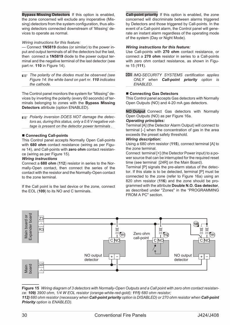
Bypass Missing Detectors If this op tion is ena bled,the zone con cer ned will ex clu de any ino pe ra ti ve (Mis -sing) de tec tors from the system con fi gu ra tion, thus al lo -wing de tec tors con nec ted downstre am of ‘Mis sing’ de -vi ces to ope ra te as nor mal.
Wi ring in struc tions for this fe a tu re:— Con nect 1N5819 dio des (or si mi lar) to the po wer in -put and out put ter mi nals of all the de tec tors but the last,then con nect a 1N5819 dio de to the po wer out put ter -mi nal and the ne ga ti ve ter mi nal of the last de tec tor (seepart nr. 110 in Fi gu re 14).
+ The po la rity of the dio des must be ob ser ved (seeFi gu re 14: the whi te band on part nr. 110 in di ca testhe cat ho de.
The Con trol pa nel mo ni tors the system for “Mis sing” de -vi ces by in ver ting the po la rity (every 60 se conds) of ter -mi nals be lon ging to zo nes with the Bypass Mis singDe tec tors at tri bu te (op tion ENABLED).
+ Po la rity in ver sion DOES NOT da ma ge the de tec -tors as, du ring this sta tus, only a 0.6 V ne ga ti ve vol -ta ge is pre sent on the de tec tor po wer ter mi nals .
n Connecting Call-pointsThis Con trol pa nel ac cepts Nor mally Open Call-po intswith 680 ohm con tact re si stan ce (wi ring as per Fi gu -re 14), and Call-po ints with zero ohm con tact re si stan -ce (wi ring as per Fi gu re 15).Wi ring in struc tionsCon nect a 680 ohm (112) re si stor in se ries to the Nor -mally-Open con tact, then con nect the se ries of thecon tact with the re si stor and the Nor mally-Open con tact to the zone ter mi nal.
If the Call po int is the last de vi ce or the zone, con nectthe EOL (109) to its NO and C ter mi nals.
Call-point priority If this op tion is ena bled, the zonecon cer ned will di scri mi na te bet we en alarms trig ge redby De tec tors and tho se trig ge red by Call-po ints. In theevent of a Call-po int alarm, the Con trol pa nel will ge ne -ra te an in stant alarm re gar dless of the ope ra ting modeof the system (Day or Night Mode).
Wi ring in struc tions for this fe a tu re:Use Call-po ints with 270 ohm con tact re si stan ce, orcon nect a 270 ohm re si stor in se ries to a Call-po intswith zero ohm con tact re si stan ce, as shown in Fi gu -re 15 (111).
A IMQ-SECURITY SYSTEMS cer ti fi ca tion ap pliesONLY when Call-po int prio rity op tion isENABLED.
n Connecting Gas DetectorsThis Con trol pa nel ac cepts Gas de tec tors with Nor mally Open Out puts (NO) and 4-20 mA gas de tec tors.
NO Output Con nect Gas de tec tors with Nor mallyOpen Out puts (NO) as per Fi gu re 16a.Ope ra ting prin ci ples: Ter mi nal [A] (the De tec tor Alarm Out put) will con nect toter mi nal [–] when the con cen tra tion of gas in the areaex ce eds the pre set sa fety thre shold.Wi ring de scrip tion: Using a 680 ohm re si stor (115), con nect ter mi nal [A] tothe zone ter mi nal.Con nect ter mi nal [+] (the De tec tor Po wer in put) to a po -wer so ur ce that can be in ter rup ted for the re qui red re set time (see ter mi nal [24R] on the Main Bo ard).Ter mi nal [P] si gnals the pre-alarm sta tus of the de tec -tor. If this sta te is to be de tec ted, ter mi nal [P] must becon nec ted to the zone (re fer to Fi gu re 16a) using an820 ohm re si stor (116) and the zone sho uld be pro -gram med with the at tri bu te Do u ble N.O. Gas de tec tor,as de scri bed un der "Zo nes" in the “PROGRAMMINGFROM A PC" section.
30 Conventional Fire Panels J424/J408
NOC
Z3
R3
24R
NOC NOC
Zero ohmcall-pointM
ain
bo
ard
or
Exp
an
de
r b
oa
rdM
ain
bo
ard
112
NO outputdetector
111 111
NO outputdetector
109
Fi gu re 15 Wi ring dia gram of 3 de tec tors with Nor mally-Open Out puts and a Call po int with zero ohm con tact re si stan -ce: 109) 3900 ohm, 1/4 W EOL re si stor (oran ge-whi te-red-gold); 111) 680 ohm re si stor; 112) 680 ohm re si stor (necessary when Call-po int priority op tion is DISABLED) or 270 ohm re si stor when Call-po int Priority op tion is ENABLED).
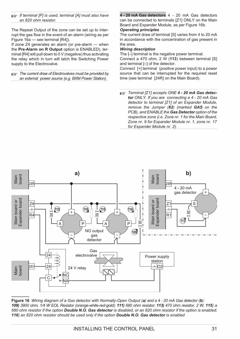
+ If ter mi nal [P] is used, ter mi nal [A] must also havean 820 ohm re si stor.
The Re pe at Out put of the zone can be set up to in ter -rupt the gas flow in the event of an alarm (wi ring as perFi gu re 16a — see ter mi nal [R4]). If zone Z4 ge ne ra tes an alarm (or pre-alarm — whenthe Pre-Alarm on R Out put op tion is ENABLED), ter -mi nal [R4] will pull down to 0 V (ne ga ti ve) thus ac ti va ting the re lay which in turn will latch the Swit ching Po wersupply to the Elec tro val ve.
+ The cur rent draw of Elec tro val ves must be pro vi ded byan ex ter nal po wer so ur ce (e.g. BXM Po wer Sta tion).
4 - 20 mA Gas detectors 4 - 20 mA Gas de tec torscan be con nec ted to ter mi nals [Z1] ONLY on the MainBo ard and Expan der Mo du le, as per Fi gu re 16b.Ope ra ting prin ci ples The cur rent draw of ter mi nal [S] va ries from 4 to 20 mAin ac cor dan ce with the con cen tra tion of gas pre sent inthe area.Wi ring de scrip tionThe [–] ter mi nal is the ne ga ti ve po wer ter mi nal. Con nect a 470 ohm, 2 W (113) bet we en ter mi nal [S]and ter mi nal [–] of the de tec tor.Con nect [+] ter mi nal (po si ti ve po wer in put) to a po werso ur ce that can be in ter rup ted for the re qui red re settime (see ter mi nal [24R] on the Main Bo ard).
+ Ter mi nal [Z1] ac cepts ONE 4 - 20 mA Gas de tec -tor ONLY. If you are con nec ting a 4 - 20 mA Gasde tec tor to ter mi nal [Z1] of an Expan der Mo du le,re mo ve the Jum per (62) (mar ked GAS on thePCB), and ENABLE the Gas De tec tor op tion of the re spec ti ve zone (i.e. Zone nr. 1 for the Main Bo ard,Zone nr. 9 for Expan der Mo du le nr. 1, zone nr. 17 for Expan der Mo du le nr. 2).
INSTALLING THE CONTROL PANEL 31
Z4
R4
24R
A P A P
Z1
R1
24R
Gaselectrovalve
O2
Power supplystation
S
NC
NA
24
24
C
24 V relay24V
NO outputgas
detector
Ma
in b
oa
rd o
rE
xpa
nd
er
bo
ard
Ma
inb
oa
rd
115 115
Ma
in b
oa
rd o
rE
xpa
nd
er
bo
ard
Ma
inb
oa
rd
Ma
inb
oa
rd
113
a) b)
4 - 20 mAgas detector
109
116 116
Fi gu re 16 Wi ring dia gram of a Gas de tec tor with Nor mally-Open Out put (a) and a 4 - 20 mA Gas de tec tor (b): 109) 3900 ohm, 1/4 W EOL Re si stor (oran ge-whi te-red-gold); 111) 680 ohm re si stor; 113) 470 ohm re si stor, 2 W; 115) a680 ohm re si stor if the op tion Do u ble N.O. Gas de tec tor is di sa bled, or an 820 ohm re si stor if the op tion is ena bled;116) an 820 ohm re si stor sho uld be used only if the op tion Do u ble N.O. Gas de tec tor is ena bled
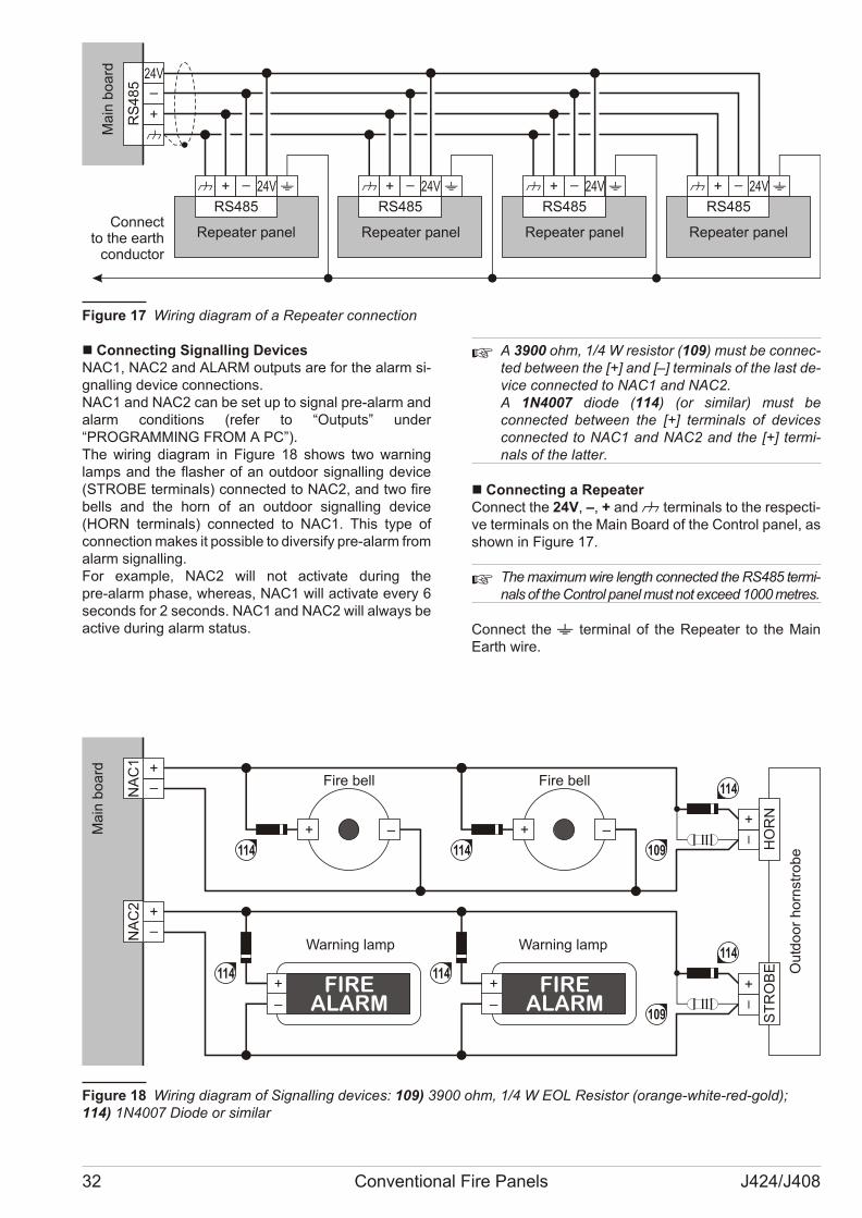
n Connecting Signalling DevicesNAC1, NAC2 and ALARM out puts are for the alarm si -gnal ling de vi ce con nec tions.NAC1 and NAC2 can be set up to si gnal pre-alarm andalarm con di tions (re fer to “Out puts” un der“PROGRAMMING FROM A PC”).The wi ring dia gram in Fi gu re 18 shows two war ninglamps and the fla sher of an out do or si gnal ling de vi ce(STROBE ter mi nals) con nec ted to NAC2, and two firebells and the horn of an out do or si gnal ling de vi ce(HORN ter mi nals) con nec ted to NAC1. This type ofcon nec tion ma kes it pos si ble to di ver sify pre-alarm from alarm si gnal ling.For exam ple, NAC2 will not ac ti va te du ring thepre-alarm pha se, whe re as, NAC1 will ac ti va te every 6se conds for 2 se conds. NAC1 and NAC2 will al ways beac ti ve du ring alarm sta tus.
+ A 3900 ohm, 1/4 W re si stor (109) must be con nec -ted bet we en the [+] and [–] ter mi nals of the last de -vi ce con nec ted to NAC1 and NAC2.A 1N4007 dio de (114) (or si mi lar) must becon nec ted bet we en the [+] ter mi nals of de vi cescon nec ted to NAC1 and NAC2 and the [+] ter mi -nals of the lat ter.
n Connecting a RepeaterCon nect the 24V, –, + and M ter mi nals to the re spec ti -ve ter mi nals on the Main Bo ard of the Con trol pa nel, asshown in Fi gu re 17.
+ The ma xi mum wire length con nec ted the RS485 ter mi -nals of the Con trol pa nel must not ex ce ed 1000 me tres.
Con nect the - ter mi nal of the Re pe a ter to the MainEarth wire.
32 Conventional Fire Panels J424/J408
24V
RS
48
5
24V
RS485
24V
RS485
24V
RS485
24V
RS485
Ma
in b
oa
rd
Repeater panelRepeater panelRepeater panelRepeater panelConnect
to the earthconductor
Fi gu re 17 Wi ring dia gram of a Re pe a ter con nec tion
–+ –+
NA
C1
FIREALARM–
+ FIREALARM–
+
HO
RN
ST
RO
BE
NA
C2
Ou
tdo
or
ho
rnst
rob
e
Ma
in b
oa
rd
114 114
114Fire bell Fire bell
Warning lamp114
114 114
Warning lamp
109
109
Fi gu re 18 Wi ring dia gram of Si gnal ling de vi ces: 109) 3900 ohm, 1/4 W EOL Re si stor (oran ge-whi te-red-gold); 114) 1N4007 Dio de or si mi lar
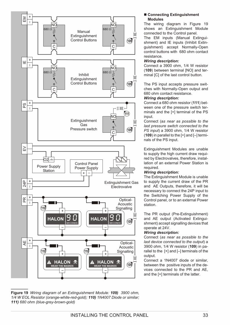
n Connecting ExtinguishmentModules
The wi ring dia gram in Fi gu re 19shows an Extin gui shment Mo du lecon nec ted to the Con trol pa nel.The EM in puts (Ma nual Extin gui -shment) and IE in puts (Inhi bit Extin -gui shment) ac cept Nor mally-Opencon trol but tons with 680 ohm con tactre si stan ce. Wi ring de scrip tion:Con nect a 3900 ohm, 1/4 W re si stor(109) bet we en ter mi nal [NO] and ter -mi nal [C] of the last con trol but ton.
The PS in put ac cepts pres su re swit -ches with Nor mally-Open out put and680 ohm con tact re si stan ce. Wi ring de scrip tion:Con nect a 680 ohm re si stor (111) bet -we en one of the pres su re switch ter -mi nals and the [+] ter mi nal of the PSin put.Con nect (as near as pos si ble to thelast pres su re switch con nec ted to thePS in put) a 3900 ohm, 1/4 W re si stor(109) in pa ral lel to the [+] and [–] ter mi -nals of the PS in put.
Extin gui shment Mo du les are una bleto supply the high cur rent draw re qui -red by Elec tro val ves, the re fo re, in stal -la tion of an ex ter nal Po wer Sta tion isre qui red.Wi ring de scrip tion:The Extin gui shment Mo du le is una bleto supply the cur rent draw of the PRand AE Out puts, the re fo re, it will bene ces sary to con nect the 24P in put tothe Swit ching Po wer Supply of theCon trol pa nel, or to an ex ter nal Po wersta tion.
The PR out put (Pre-Extin gui shment)and AE out put (Acti va ted Extin gui -shment) ac cept si gnal ling de vi ces that ope ra te at 24V.Wi ring de scrip tion:Con nect (as near as pos si ble to thelast de vi ce con nec ted to the out put) a3900 ohm, 1/4 W re si stor (109) in pa -ral lel to the [+] and [–] ter mi nals of theout put.Con nect a 1N4007 dio de or si mi lar,bet we en the po si ti ve in puts of the de -vi ces con nec ted to the PR and AE,and the [+] ter mi nals of the lat ter.
INSTALLING THE CONTROL PANEL 33
O2
EM
PS
NO
C
NO
C
NO
C
NO
C
IEE
VP
R2
4P
AE
–
+
HALONWEAR THE MASKES
–
+
HALONWEAR THE MASKES
–
+
HALONSECONDS
–
+
HALONSECONDS
NO
C
ManualExtinguishmentControl Buttons
680 W 680 W
680 W 680 W
Power SupplyStation
Control PanelPower Supply
InhibitExtinguishmentControl Buttons
ExtinguishmentGas
Pressure switch
Extinguishment GasElectrovalve
Optical-Acoustic
Signalling
Optical-Acoustic
Signalling110 110
109
110
111
109
109
109
109
Fi gu re 19 Wi ring dia gram of an Extin gui shment Mo du le: 109) 3900 ohm,1/4 W EOL Re si stor (oran ge-whi te-red-gold); 110) 1N4007 Dio de or si mi lar;111) 680 ohm (blue-grey-brown-gold)
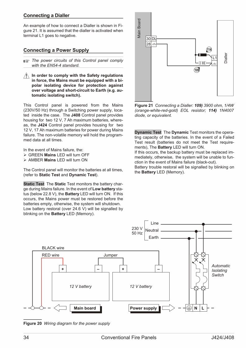
Connecting a Dialler
An exam ple of how to con nect a Dial ler is shown in Fi -gu re 21. It is as su med that the dial ler is ac ti va ted whenter mi nal L1 goes to ne ga ti ve.
Connecting a Power Supply
+ The po wer cir cu its of this Con trol pa nel complywith the EN54-4 stan dard.
! In or der to comply with the Sa fety re gu la tionsin for ce, the Ma ins must be equip ped with a bi -po lar iso la ting de vi ce for pro tec tion aga instover vol ta ge and short-cir cu it to Earth (e.g. au -to ma tic iso la ting switch).
This Con trol pa nel is po we red from the Ma ins(230V/50 Hz) thro ugh a Swit ching po wer supply, lo ca -ted in si de the case. The J408 Con trol pa nel pro vi desho u sing for two 12 V, 7 Ah ma xi mum bat te ries, whe re -as, the J424 Con trol pa nel pro vi des ho u sing for two12 V, 17 Ah ma xi mum bat te ries for po wer du ring Ma insfa i lu re. The non-vo la ti le me mory will hold the pro gram -med data at all ti mes.
In the event of Ma ins fa i lu re, the:Ø GREEN Ma ins LED will turn OFFØ AMBER Ma ins LED will turn ON
The Con trol pa nel will mo ni tor the bat te ries at all ti mes,(re fer to Sta tic Test and Dyna mic Test).
Static Test The Sta tic Test mo ni tors the bat tery char -ge du ring Ma ins fa i lu re. In the event of Low bat tery sta -tus (be low 22.8 V), the Bat tery LED will turn ON. If thisoc curs, the Ma ins po wer must be re sto red be fo re thebat te ries empty, ot her wi se, the system will shut down.Low bat tery re sto ral (over 24.6 V) will be si gnal led byblin king on the Bat tery LED (Me mory).
Dynamic Test The Dyna mic Test mo ni tors the ope ra -ting ca pa city of the bat te ries. In the event of a Fa i ledTest re sult (bat te ries do not meet the Test re qui re -ments), The Bat tery LED will turn ON.If this oc curs, the bac kup bat tery must be re pla ced im -me dia tely, ot her wi se, the system will be una ble to fun -ction in the event of Ma ins fa i lu re (black-out).Bat tery tro u ble re sto ral will be si gnal led by blin king onthe Bat tery LED (Me mory).
34 Conventional Fire Panels J424/J408
LMain board N
AutomaticIsolatingSwitch
+ –
12 V battery
Line
Neutral
Earth
230 V50 Hz
+ –
12 V battery
Power supply
RED wire
BLACK wire
Jumper
Fi gu re 20 Wi ring dia gram for the po wer supply
L1
DL30
28
Dia
ller
Ma
in B
oa
rd
114
109
Fi gu re 21 Con nec ting a Dial ler: 109) 3900 ohm, 1/4W(oran ge-whi te-red-gold) EOL re si stor; 114) 1N4007dio de, or equi va lent.
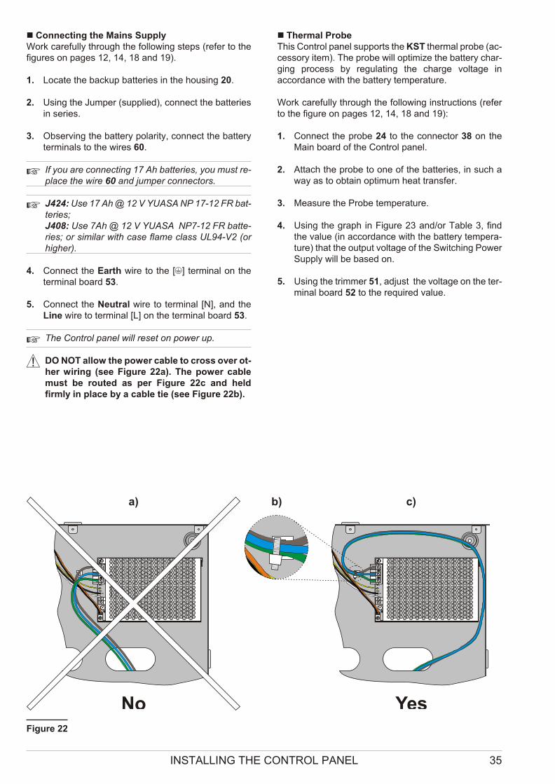
n Connecting the Mains SupplyWork ca re fully thro ugh the fol lo wing steps (re fer to thefi gu res on pa ges 12, 14, 18 and 19).
1. Lo ca te the bac kup bat te ries in the ho u sing 20.
2. Using the Jum per (sup plied), con nect the bat te riesin se ries.
3. Obser ving the bat tery po la rity, con nect the bat teryter mi nals to the wi res 60.
+ If you are con nec ting 17 Ah bat te ries, you must re -pla ce the wire 60 and jum per con nec tors.
+ J424: Use 17 Ah @ 12 V YUASA NP 17-12 FR bat -te ries;J408: Use 7Ah @ 12 V YUASA NP7-12 FR bat te -ries; or si mi lar with case fla me class UL94-V2 (orhi gher).
4. Con nect the Earth wire to the [Q] ter mi nal on theter mi nal bo ard 53.
5. Con nect the Ne u tral wire to ter mi nal [N], and theLine wire to ter mi nal [L] on the ter mi nal bo ard 53.
+ The Con trol pa nel will re set on po wer up.
! DO NOT al low the po wer ca ble to cross over ot -her wi ring (see Fi gu re 22a). The po wer ca blemust be ro u ted as per Fi gu re 22c and heldfirmly in pla ce by a ca ble tie (see Fi gu re 22b).
n Thermal ProbeThis Con trol pa nel sup ports the KST ther mal pro be (ac -ces sory item). The pro be will op ti mi ze the bat tery char -ging pro cess by re gu la ting the char ge vol ta ge inac cor dan ce with the bat tery tem pe ra tu re.
Work ca re fully thro ugh the fol lo wing in struc tions (re ferto the fi gu re on pa ges 12, 14, 18 and 19):
1. Con nect the pro be 24 to the con nec tor 38 on theMain bo ard of the Con trol pa nel.
2. Attach the pro be to one of the bat te ries, in such away as to ob ta in op ti mum heat tran sfer.
3. Me a su re the Pro be tem pe ra tu re.
4. Using the graph in Fi gu re 23 and/or Ta ble 3, findthe va lue (in ac cor dan ce with the bat tery tem pe ra -tu re) that the out put vol ta ge of the Swit ching Po werSupply will be ba sed on.
5. Using the trim mer 51, ad just the vol ta ge on the ter -mi nal bo ard 52 to the re qui red va lue.
INSTALLING THE CONTROL PANEL 35
AC
/NFG
+VG
ND
B+
L
B–
GND
+V
AC
/L
F 3
.1
5A
/25
ØV
F 6
.3
A/2
5Ø
V
AC
/NFG
+VG
ND
B+
L
B–
GND
+V
AC
/L
F 3
.1
5A
/25
ØV
F 6
.3
A/2
5Ø
V
a) b) c)
No YesFi gu re 22
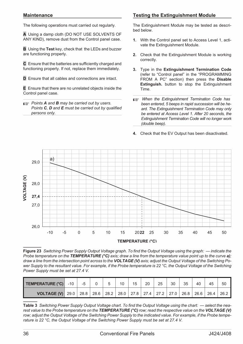
Maintenance
The fol lo wing ope ra tions must car ried out re gu larly.
A Using a damp cloth (DO NOT USE SOLVENTS OFANY KIND), re mo ve dust from the Con trol pa nel case.
B Using the Test key, check that the LEDs and buz zerare fun ctio ning pro perly.
C Ensu re that the bat te ries are suf fi ciently char ged and fun ctio ning pro perly. If not, re pla ce them im me dia tely.
D Ensu re that all ca bles and con nec tions are in tact.
E Ensu re that the re are no un re la ted ob jects in si de theCon trol pa nel case.
+ Po ints A and B may be car ried out by users. Po ints C, D and E must be car ried out by qua li fiedper sons only.
Te sting the Extin gui shment Mo du le
The Extin gui shment Mo du le may be te sted as de scri -bed be low.
1. With the Con trol pa nel set to Access Le vel 1, ac ti -va te the Extin gui shment Mo du le.
2. Check that the Extin gui shment Mo du le is wor kingcor rectly.
3. Type in the Extin gui shment Ter mi na tion Code(re fer to “Con trol pa nel” in the “PROGRAMMINGFROM A PC” sec tion) then press the Di sa bleExtin guish. button to stop the Extin gui shmentTime.
+ When the Extin gui shment Ter mi na tion Code hasbeen en te red, 5 be eps in ra pid suc ces sion will be he -ard. The Extin gui shment Ter mi na tion Code may onlybe en te red at Access Le vel 1. After 20 se conds, theExtin gui shment Ter mi na tion Code will no lon ger work(do u ble beep).
4. Check that the EV Out put has been disactivated.
36 Conventional Fire Panels J424/J408
TEMPERATURE (°C) -10 -5 0 5 10 15 20 25 30 35 40 45 50
VOLTAGE (V) 29.0 28.8 28.6 28.2 28.0 27.8 27.4 27.2 27.0 26.8 26.6 26.4 26.2
Ta ble 3 Swit ching Po wer Supply Out put Vol ta ge chart. To find the Out put Vol ta ge using the chart: — se lect the ne a -rest va lue to the Pro be tem pe ra tu re on the TEMPERATURE (°C) row; read the re spec ti ve va lue on the VOLTAGE (V)row; ad just the Out put Vol ta ge of the Swit ching Po wer Supply to the in di ca ted va lue. For exam ple, if the Pro be tem pe -ra tu re is 22 °C, the Out put Vol ta ge of the Swit ching Po wer Supply must be set at 27.4 V.
-10 -5 0 5 10 15 20 25 30 35 40 45 50
26,0
27,0
28,0
29,0
VO
LTA
GE
(V
)
TEMPERATURE (°C)
a)
27,4
22
Fi gu re 23 Swit ching Po wer Supply Out put Vol ta ge graph. To find the Out put Vol ta ge using the graph: — in di ca te thePro be tem pe ra tu re on the TEMPERATURE (°C) axis; draw a line from the tem pe ra tu re va lue po int up to the cur ve a);draw a line from the in ter sec tion po int across to the VOLTAGE (V) axis; ad just the Out put Vol ta ge of the Swit ching Po -wer Supply to the re sul tant va lue. For exam ple, if the Pro be tem pe ra tu re is 22 °C, the Out put Vol ta ge of the Swit chingPo wer Supply must be set at 27.4 V.
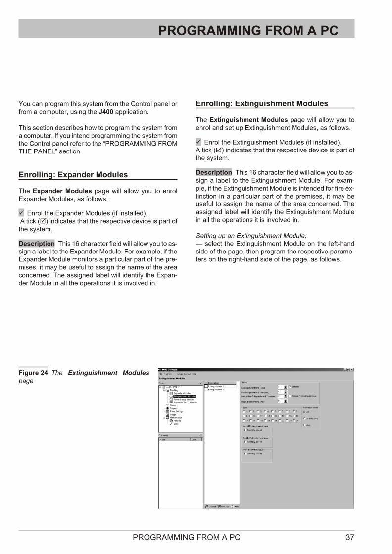
PROGRAMMING FROM A PC
You can pro gram this system from the Con trol pa nel orfrom a com pu ter, using the J400 ap pli ca tion.
This sec tion de scri bes how to pro gram the system froma com pu ter. If you in tend pro gram ming the system fromthe Con trol pa nel re fer to the “PROGRAMMING FROMTHE PANEL” sec tion.
Enrolling: Expander Modules
The Expan der Mo du les page will al low you to en rolExpan der Mo du les, as fol lows.
ü Enrol the Expan der Mo du les (if in stal led). A tick (þ) in di ca tes that the re spec ti ve de vi ce is part ofthe system.
Description This 16 cha rac ter field will al low you to as -sign a la bel to the Expan der Mo du le. For exam ple, if the Expan der Mo du le mo ni tors a par ti cu lar part of the pre -mi ses, it may be use ful to as sign the name of the areacon cer ned. The as si gned la bel will iden tify the Expan -der Mo du le in all the ope ra tions it is in vol ved in.
Enrolling: Extinguishment Modules
The Extin gui shment Mo du les page will al low you toen rol and set up Extin gui shment Mo du les, as fol lows.
ü Enrol the Extin gui shment Mo du les (if in stal led). A tick (þ) in di ca tes that the re spec ti ve de vi ce is part ofthe system.
Description This 16 cha rac ter field will al low you to as -sign a la bel to the Extin gui shment Mo du le. For exam -ple, if the Extin gui shment Mo du le is in ten ded for fire ex -tin ction in a par ti cu lar part of the pre mi ses, it may beuse ful to as sign the name of the area con cer ned. Theas si gned la bel will iden tify the Extin gui shment Mo du lein all the ope ra tions it is in vol ved in.
Set ting up an Extin gui shment Mo du le:— se lect the Extin gui shment Mo du le on the left-handside of the page, then pro gram the re spec ti ve pa ra me -ters on the right-hand side of the page, as fol lows.
PROGRAMMING FROM A PC 37
Fi gu re 24 The Extin gui shment Mo du lespage
n Activation ModeThis sec tion will al low you to se lect the lo gic that will ac -ti va te the Extin gui shment pha se, as fol lows.
+ When some zo nes are in alarm, a con di tion ofpre-ac ti va tion is si gnal led by the Con trol pa nel byme ans of the ON Pre. Ext., which fla shes quickly.
OR If you ENABLE this op tion, at le ast ONE of the Zo -nes — se lec ted in the Zo nes chart — must de tect alarm con di tions.
At least TWO If you ENABLE this op tion, at le ast TWO of the Zo nes — se lec ted in the Zo nes chart — must de -tect alarm con di tions.
All If you ENABLE this op tion, ALL the Zo nes — se lec -ted in the Zo nes chart — must de tect alarm con di tions.
n TimesThis sec tion will al low you to set the Extin gui shment Ti -mes.
Pre-Extinguishment Time This field will al low you topro gram a de lay bet we en ve ri fi ca tion of the Acti va tionMode con di tions and ac ti va tion of the Elec tro val ve out -put ([EV] ter mi nals). The Pre-Extin gui shment out put([PR] ter mi nals) will be ac ti ve du ring the Pre-Extin gui -shment Time.Accep ted va lu es: 0 to 60 se conds, in steps of 1 se cond.De fa ult va lue: 20 se conds.
Extinguishment Time This field will al low you to setthe Extin gui shment Time. If you DISABLE the Bi sta bleop tion, the EV out put will re sto re to standby when thepro gram med Extin gui shment Time ex pi res.Accep ted va lu es: 0 to 300 se conds (5 mi nu tes ) in steps of 5 se cond.
Bistable If you ENABLE the Bi sta ble op tion, the EVout put will re sto re to standby when the Con trol pa nelRe sets.
Ma nual Pre-Extin gui shment Time Set the time thatmust elap se from the po int at which the EM Input is ac ti -va ted to the po int at which the Elec tro val ve Out put ([EV] ter mi nals) are ac ti va ted. Du ring the Ma nual Pre-Extin -gui shment Tim e, the Pre-Extin gui shment Out put([PR] ter mi nals) is ac ti va ted.Accep ted va lu es: 0 to 60 se conds, steps of 1 se cond.De fa ult va lue: 0 se conds.
Ma nual Pre-Extin gui shment When the Ma nualPre-Extin gui shment op tion is ena bled, the Ma nualPre-Extin gui shment Time may be set. When the op tionis di sa bled, the Pre-Extin gui shment Time will also beused by the Con trol pa nel for ma nual ac ti va tion.
Reset Inhibit Time This is the amo unt of time thatmust elap se from the po int at which the Extin gui shmentMo du le is ena bled to the po int at which the mo du le maybe re set. If the re set is per for med du ring the Re set Inhi -bit Time, the Con trol pa nel will re set all systems (ex cept for the activated Extin gui shment Mo du le) for a few se -conds, af ter which it will re turn to an alarm con di tion.Accep ted va lues: 0 to 30 mi nu tes, steps of 1 mi nu te.De fa ult va lue: 0 mi nu tes.
n ZonesThis sec tion will al low you to se lect the Zo nes which willac ti va te the Extin gui shment pha se.
n Manual Extinguishment InputThis field will al low you to set up the Standby sta tus ofthe Ma nual Extin gui shment Input ([EM] ter mi nals).
Normally Closed If this op tion is DISABLED (at De fa -ult), the re must be a 3900 ohm re si stan ce across the [+] and [–] ter mi nals of the EM Input du ring Standby sta tus.When this op tion is ena bled, the re si stor in standbymust be 680 ohm.
n Disable Extinguishment InputThis field will al low you to set up the Standby sta tus ofthe Di sa ble Extin gui shment Input ([IE] ter mi nals).
Normally Closed If this op tion is DISABLED (at De fa -ult), the re must be a 3900 ohm re si stan ce across the [+] and [–] ter mi nals of the IE in put du ring Standby sta tus.When this op tion is ena bled, the re si stor in standbymust be 680 ohm.
n Pressure Switch InputThis field will al low you to set up the Standby sta tus ofthe Pres su re Switch Input ([PS] ter mi nals).
Normally Closed If this op tion is DISABLED (at De fa -ult), the re must be a 3900 ohm re si stan ce across the [+] and [–] ter mi nals of the PS in put du ring Standby sta tus.When this op tion is ena bled, the re si stor in standbymust be 680 ohm.
Enrolling: Power Supply Stations
The Po wer Supply Sta tions page will al low you to en -rol and set up Po wer Supply Sta tions, as fol lows.
ü Enrol the Po wer Supply Sta tions (if in stal led).A tick (þ) in di ca tes that the re spec ti ve Po wer SupplySta tion is part of the system.
Description This 16 cha rac ter field will al low you to as -sign a la bel to the re spec ti ve Po wer Supply Sta tion. Forexam ple, it may be use ful to as sign the name of thearea whe re the de vi ce is lo ca ted. The as si gned la belwill iden tify the Po wer Supply Sta tion in all the ope ra -tions it is in vol ved in.
38 Conventional Fire Panels J424/J408
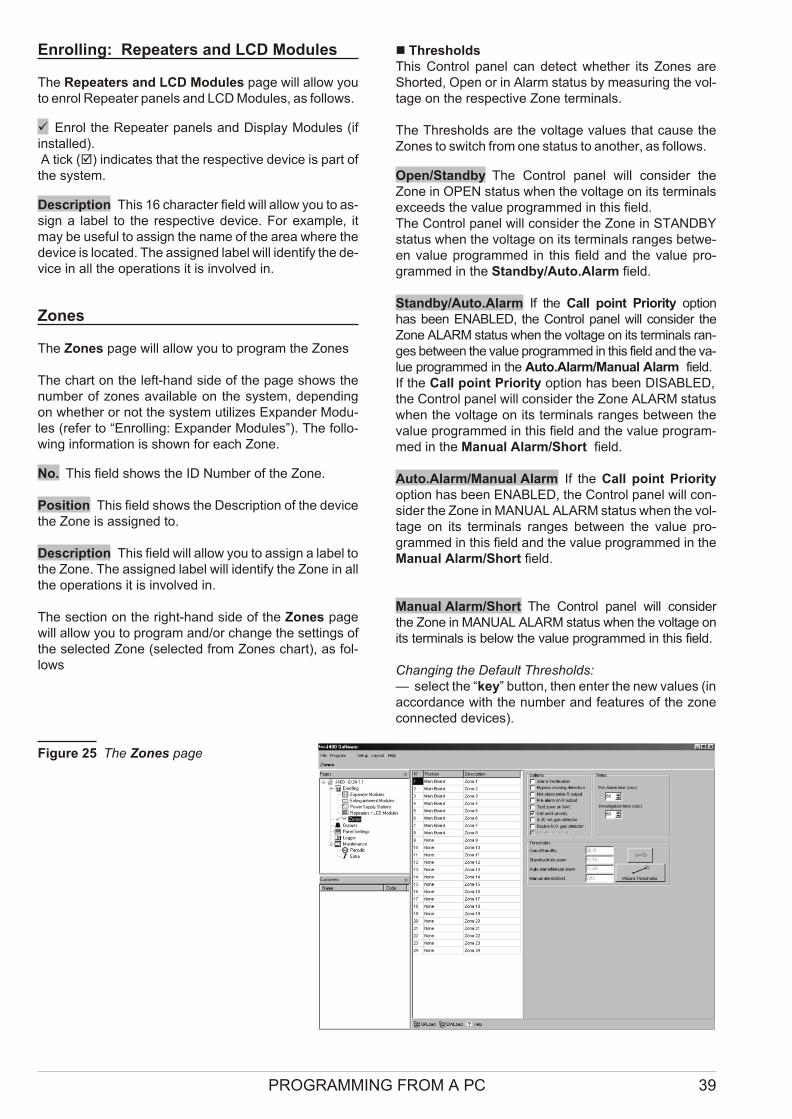
Enrolling: Repeaters and LCD Modules
The Re pe a ters and LCD Mo du les page will al low youto en rol Re pe a ter pa nels and LCD Mo du les, as fol lows.
ü Enrol the Re pe a ter pa nels and Di splay Mo du les (ifin stal led). A tick (þ) in di ca tes that the re spec ti ve de vi ce is part ofthe system.
Description This 16 cha rac ter field will al low you to as -sign a la bel to the re spec ti ve de vi ce. For exam ple, itmay be use ful to as sign the name of the area whe re thede vi ce is lo ca ted. The as si gned la bel will iden tify the de -vi ce in all the ope ra tions it is in vol ved in.
Zones
The Zo nes page will al low you to pro gram the Zo nes
The chart on the left-hand side of the page shows thenum ber of zo nes ava i la ble on the system, de pen dingon whet her or not the system uti li zes Expan der Mo du -les (re fer to “Enrol ling: Expan der Mo du les”). The fol lo -wing in for ma tion is shown for each Zone.
No. This field shows the ID Num ber of the Zone.
Position This field shows the De scrip tion of the de vi cethe Zone is as si gned to.
Description This field will al low you to as sign a la bel to the Zone. The as si gned la bel will iden tify the Zone in allthe ope ra tions it is in vol ved in.
The sec tion on the right-hand side of the Zo nes pagewill al low you to pro gram and/or chan ge the set tings ofthe se lec ted Zone (se lec ted from Zo nes chart), as fol -lows
n ThresholdsThis Con trol pa nel can de tect whet her its Zo nes areShor ted, Open or in Alarm sta tus by me a su ring the vol -ta ge on the re spec ti ve Zone ter mi nals.
The Thre sholds are the vol ta ge va lu es that ca u se theZo nes to switch from one sta tus to anot her, as fol lows.
Open/Standby The Con trol pa nel will con si der theZone in OPEN sta tus when the vol ta ge on its ter mi nalsex ce eds the va lue pro gram med in this field.The Con trol pa nel will con si der the Zone in STANDBYsta tus when the vol ta ge on its ter mi nals ran ges bet we -en va lue pro gram med in this field and the va lue pro -gram med in the Standby/Auto.Alarm field.
Standby/Auto.Alarm If the Call po int Prio rity op tionhas been ENABLED, the Con trol pa nel will con si der theZone ALARM sta tus when the vol ta ge on its ter mi nals ran -ges bet we en the va lue pro gram med in this field and the va -lue pro gram med in the Auto.Alarm/Ma nual Alarm field.If the Call po int Prio rity op tion has been DISABLED, the Con trol pa nel will con si der the Zone ALARM sta tuswhen the vol ta ge on its ter mi nals ran ges bet we en theva lue pro gram med in this field and the va lue pro gram -med in the Ma nual Alarm/Short field.
Auto.Alarm/Manual Alarm If the Call po int Prio rityop tion has been ENABLED, the Con trol pa nel will con -si der the Zone in MANUAL ALARM sta tus when the vol -ta ge on its ter mi nals ran ges bet we en the va lue pro -gram med in this field and the va lue pro gram med in theMa nual Alarm/Short field.
Manual Alarm/Short The Con trol pa nel will con si derthe Zone in MANUAL ALARM sta tus when the vol ta ge onits ter mi nals is be low the va lue pro gram med in this field.
Chan ging the De fa ult Thre sholds:— se lect the “key” but ton, then en ter the new va lu es (in ac cor dan ce with the num ber and fe a tu res of the zonecon nec ted de vi ces).
PROGRAMMING FROM A PC 39
Fi gu re 25 The Zo nes page
For step by step in struc tions on how to set up the Thre -sholds:— se lect the “Wi zard Thre sholds” but ton.
+ The “Wi zard Thre sholds” op tion can be used onlywhen the Con trol pa nel con nec ted to a com pu ter,and is in “Pro gram ming” sta tus (as de scri bed in the “Dow nlo a ding” pa ra graph).
n OptionsThis sec tion will al low you to as sign the Zone “at tri bu tes”.
Alarm Verification If this op tion is ENABLED, Alarmwill be ve ri fied as fol lows:Ø the system will not ge ne ra te a Con trol pa nel Alarm
when the Zone first de tects Alarm con di tions;Ø the system will re set the Zone and start the Alarm
Ve ri fi ca tion Time (re fer to “Pa nel set tings”);Ø if the Zone trig gers anot her Alarm whi le the Alarm
Ve ri fi ca tion Time is run ning, the system will ge ne ra te a Con trol pa nel Alarm.
Bypass missing detectors If the Zone is wi red tobypass mis sing de tec tors, this op tion MUST BE ENABLED.
NON-Silenceable R Output If this op tion isENABLED, the Re pe at Out put of the Zone con cer ned([Rn] ter mi nal) CANNOT be Si len ced.
Pre-Alarm on R Output If this op tion is ENABLED, the Con trol pa nel will ac ti va te the Re pe at Out put of the Zonecon cer ned ([Rn] ter mi nal) du ring the Pre-Alarm pha se.
Test zone on NACs If this op tion is ENABLED, theCon trol pa nel will ac ti va te the NAC1 and NAC2 Out puts for 1 se cond when the Zone is un der go es te sting.
Call point Priority If this op tion is ENABLED, the Con -trol pa nel will ge ne ra te an in stant Alarm when the ZoneCall-po int but ton is pres sed.
Gas Detector If this op tion is ENABLED, it will be pos si ble to con nect a 4 - 20 mA Gas De tec tor to the Zone ter mi nal.
+ The Gas De tec tor op tion can be ENABLED ONLYfor Zo nes 1, 9 and 17, re spec ti vely, the [Z1] ter mi -nals on the Main Bo ard, and on Expan der nr. 1 and Expan der nr. 2.
Double N.O. Gas De tec tor This op tion sho uld beena bled when using ter mi nal [P] of the de tec tor. Whenthis op tion is ENABLED, Zone thre sholds will be au to -ma ti cally ad ju sted to the con nec tion il lu stra ted in Fi gu re 16a on page 31. Thus, the Con trol pa nel will be able tode tect 2 ac ti va tion thre sholds, one for the Pre-Alarmand one for the Alarm.
R Output Bistable This op tion is only ava i la ble whenthe Do u ble N.O. Gas de tec tor is ena bled.In this case, when the op tion R Out put Bi sta ble is ena -bled, the R Out put of the zone is ac ti va ted when the zone ex ce eds the alarm thre shold (or the pre-alarm thre shold,if the op tion “Pre-Alarm on R Out put” is ena bled) and re -
turns to standby when the zone falls be low the alarmthre shold, ir re spec ti vely of the Con trol pa nel sta tus. If the op tion R Out put Bi sta ble is di sa bled (fac tory de -fa ult), the R Out put re turns to standby when the Con trolpa nel is re set.
n Times
Pre-Alarm Time This field will al low you to pro gram thede lay bet we en the Zone Alarm and the Con trol pa nel Alarm.
+ If se ve ral Zo nes trig ger Alarms wit hin se conds ofone anot her, the Con trol pa nel will ge ne ra te anAlarm when the shor test Pre-Alarm Time of all theZo nes con cer ned ex pi res.
Accep ted va lu es: 0 to 300 se conds (5 mi nu tes), in steps of 10 se conds.De fa ult set ting: 60 se conds.
Investigation Time This field wilI al low you to pro gram an “in ter val” that will over ri de the Pre-Alarm Time. This“in ter val” will al low users time to in ve sti ga te fire alerts. It will be ap plied when the Ack/Evac. key is pres sed forless than 5 se conds at Access Le vel 2 (Key switchENABLED or PIN Code en te red).Accep ted va lu es: 0 to 300 se conds (5 mi nu tes), in steps of 10 se condsDe fa ult va lue: 60 se conds.
Outputs
The Out puts page con trols the pul se pat tern forPre-Alarm (Alert) and/or Alarm (Eva cua te) si gnal ling on the NAC1 and NAC2 out puts, and Alarm (Eva cua te) si -gnal ling on the ALARM out put.
The pat tern is re pre sen ted by a se ries of bells, each bell re pre sen ting a se cond.
The con fi gu ra tion of the RED and WHITE backgro unds (for On and Off re spec ti vely e.g. all RED in di ca tes con ti -nu o usly On) de ter mi nes the re spec ti ve pul se pat tern.
For exam ple, the out put de vi ces (con nec ted toNAC1and NAC2) can be con fi gu red to have one au di -ble out put for Pre-Alarm (Alert) and a dif fe rent au di bleout put for Alarm (Eva cua te), thus al lo wing users to di -stin guish bet we en the two con di tions, as fol lows.
n NAC1 Output
Pre-Alarm pattern The bell chart will al low you to pro -gram the Pre-Alarm (Alert) pat tern of NAC1.
Ø = Out put OFF for 1 se cond;
Ø = Out put ON for 1 se cond.Pre-Alarm De fa ult set ting: NAC1 will turn ON for 2 se -conds then turn OFF for 6 se conds.
Alarm pattern To be set up in the same way as thePre-Alarm pat tern of NAC1 but for the Alarm pat tern.De fa ult set ting: NAC1 is con ti nu o us.
40 Conventional Fire Panels J424/J408
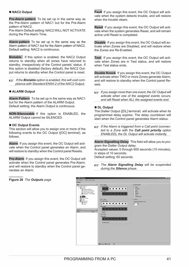
n NAC2 Output
Pre-Alarm pattern To be set up in the same way asthe Pre-Alarm pat tern of NAC1 but for the Pre-Alarmpat tern of NAC2.Pre-Alarm De fa ult set ting: NAC2 WILL NOT ACTIVATE du ring the Pre-Alarm Time.
Alarm pattern To be set up in the same way as theAlarm pat tern of NAC1 but for the Alarm pat tern of NAC2.De fa ult set ting: NAC2 is con ti nu o us.
Bi sta ble If this op tion is ena bled, the NAC2 Out putre turns to standby when all zo nes have re tur ned tostandby, ir re spec ti vely of the Con trol pa nels’ sta tus. Ifthis op tion is di sa bled (fac tory de fa ult), the NAC2 Out -put re turns to standby when the Con trol pa nel is re set.
+ If the Bi sta ble op tion is ena bled, this will void com -plian ce with Stan dard EN54-2 of the NAC2 Out put.
n ALARM Output
Alarm Pattern To be set up in the same way as NAC1but for the Alarm pat tern of the ALARM Out put.De fa ult set ting: the Alarm Out put is con ti nu o us.
NON-Silenceable If this op tion is ENABLED, theALARM Out put can not be SILENCED.
n OC Output EventsThis sec tion will al low you to as sign one or more of thefol lo wing events to the OC Out put ([OC] ter mi nal), asfol lows.
Alarm If you as sign this event, the OC Out put will ac ti -va te when the Con trol pa nel ge ne ra tes an Alarm, andwill re sto re to standby when the Con trol pa nel Re sets.
Pre-Alarm If you as sign this event, the OC Out put willac ti va te when the Con trol pa nel ge ne ra tes Pre-Alarm,and will re sto re to standby when the Con trol pa nel ge -ne ra tes an Alarm.
Fault If you as sign this event, the OC Out put will ac ti -va te when the system de tects tro u ble, and will re sto rewhen the tro u ble cle ars.
Reset If you as sign this event, the OC Out put will ac ti -va te when the system ge ne ra tes Re set, and will re ma inac ti ve un til Re set is com ple ted.
Disable If you as sign this event, the OC Out put will ac -ti va te when Zo nes are Di sa bled, and will re sto re whenthe Zo nes are Re-Ena bled.
Test If you as sign this event, the OC Out put will ac ti -va te when Zo nes are in Test sta tus, and will re sto rewhen Test sta tus ends.
Double Knock If you as sign this event, the OC Out putwill ac ti va te when TWO or more Zo nes ge ne ra te Alarm,and will re sto re to standby when the Con trol pa nel Re -sets.
+ If you as sign more than one event, the OC Out put will ac ti va te when one of the as si gned events oc curs,and will Re set when ALL the as si gned events end.
n DL OutputThe Dial ler Out put ([DL] ter mi nal) will ac ti va te when itspro gram med de lay ex pi res. The de lay co un tdown willstart when the Con trol pa nel ge ne ra tes Alarm sta tus.
+ If the Alarm is trig ge red from a Call po int (con nec -ted to a Zone with the Call po int prio rity op tionENABLED), the DL Out put will ac ti va te in stantly.
Alarm Signalling Delay This field will al low you to pro -gram the Dial ler Out put de lay. Accep ted va lu es: 0 thro ugh 600 se conds (10 mi nu tes),in steps of 10 se conds; De fa ult set ting: 60 se conds.
+ The Alarm Si gnal ling De lay will be su spen deddu ring the Si len ce pha se.
PROGRAMMING FROM A PC 41
Fi gu re 26 The Out puts page
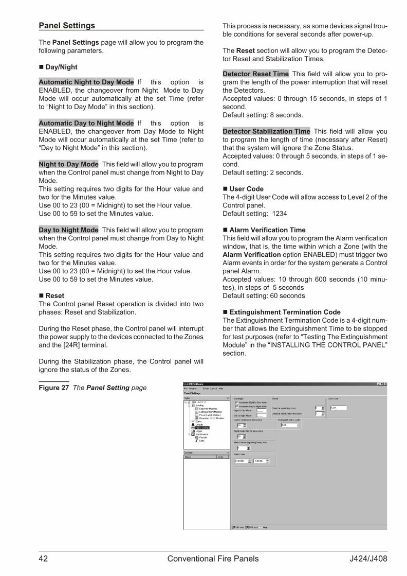
Panel Settings
The Pa nel Set tings page will al low you to pro gram thefol lo wing pa ra me ters.
n Day/Night
Automatic Night to Day Mode If this op tion isENABLED, the chan ge o ver from Night Mode to DayMode will oc cur au to ma ti cally at the set Time (re ferto “Night to Day Mode” in this sec tion).
Automatic Day to Night Mode If this op tion isENABLED, the chan ge o ver from Day Mode to NightMode will oc cur au to ma ti cally at the set Time (re fer to“Day to Night Mode” in this sec tion).
Night to Day Mode This field will al low you to pro gram when the Con trol pa nel must chan ge from Night to DayMode.This set ting re qui res two di gits for the Hour va lue andtwo for the Mi nu tes va lue.Use 00 to 23 (00 = Mid night) to set the Hour va lue.Use 00 to 59 to set the Mi nu tes va lue.
Day to Night Mode This field will al low you to pro gram when the Con trol pa nel must chan ge from Day to NightMode.This set ting re qui res two di gits for the Hour va lue andtwo for the Mi nu tes va lue.Use 00 to 23 (00 = Mid night) to set the Hour va lue.Use 00 to 59 to set the Mi nu tes va lue.
n ResetThe Con trol pa nel Re set ope ra tion is di vi ded into twopha ses: Re set and Sta bi li za tion.
Du ring the Re set pha se, the Con trol pa nel will in ter ruptthe po wer supply to the de vi ces con nec ted to the Zo nes and the [24R] ter mi nal.
Du ring the Sta bi li za tion pha se, the Con trol pa nel willigno re the sta tus of the Zo nes.
This pro cess is ne ces sary, as some de vi ces si gnal tro u -ble con di tions for se ve ral se conds af ter po wer-up.
The Re set sec tion will al low you to pro gram the De tec -tor Re set and Sta bi li za tion Ti mes.
Detector Reset Time This field will al low you to pro -gram the length of the po wer in ter rup tion that will re setthe De tec tors.Accep ted va lu es: 0 thro ugh 15 se conds, in steps of 1se cond.De fa ult set ting: 8 se conds.
Detector Stabilization Time This field will al low youto pro gram the length of time (ne ces sary af ter Re set)that the system will igno re the Zone Sta tus.Accep ted va lu es: 0 thro ugh 5 se conds, in steps of 1 se -cond.De fa ult set ting: 2 se conds.
n User CodeThe 4-di git User Code will al low ac cess to Le vel 2 of theCon trol pa nel.De fa ult set ting: 1234
n Alarm Verification TimeThis field will al low you to pro gram the Alarm ve ri fi ca tion win dow, that is, the time wit hin which a Zone (with theAlarm Ve ri fi ca tion op tion ENABLED) must trig ger twoAlarm events in or der for the system ge ne ra te a Con trolpa nel Alarm.Accep ted va lu es: 10 thro ugh 600 se conds (10 mi nu -tes), in steps of 5 se condsDe fa ult set ting: 60 se conds
n Extinguishment Termination CodeThe Extin gui shment Ter mi na tion Code is a 4-di git num -ber that al lows the Extin gui shment Time to be stop pedfor test pur po ses (re fer to “Te sting The Extin gui shmentMo du le” in the “INSTALLING THE CONTROL PANEL”sec tion.
42 Conventional Fire Panels J424/J408
Fi gu re 27 The Pa nel Set ting page
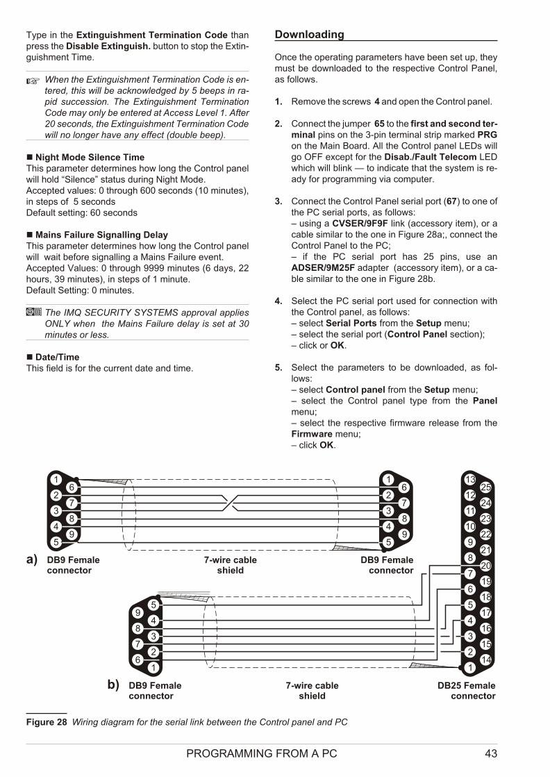
Type in the Extin gui shment Ter mi na tion Code thanpress the Di sa ble Extin guish. but ton to stop the Extin -gui shment Time.
+ When the Extin gui shment Ter mi na tion Code is en -te red, this will be ac know led ged by 5 be eps in ra -pid suc ces sion. The Extin gui shment Ter mi na tionCode may only be en te red at Access Le vel 1. After20 se conds, the Extin gui shment Ter mi na tion Code will no lon ger have any ef fect (do u ble beep).
n Night Mode Silence TimeThis pa ra me ter de ter mi nes how long the Con trol pa nelwill hold “Si len ce” sta tus du ring Night Mode.Accep ted va lu es: 0 thro ugh 600 se conds (10 mi nu tes),in steps of 5 se condsDe fa ult set ting: 60 se conds
n Mains Failure Signalling DelayThis pa ra me ter de ter mi nes how long the Con trol pa nelwill wait be fo re si gnal ling a Ma ins Fa i lu re event.Accep ted Va lu es: 0 thro ugh 9999 mi nu tes (6 days, 22ho urs, 39 mi nu tes), in steps of 1 mi nu te. De fa ult Set ting: 0 mi nu tes.
A The IMQ SECURITY SYSTEMS ap pro val ap pliesONLY when the Ma ins Fa i lu re de lay is set at 30mi nu tes or less.
n Date/TimeThis field is for the cur rent date and time.
Downloading
Once the ope ra ting pa ra me ters have been set up, theymust be dow nlo a ded to the re spec ti ve Con trol Pa nel,as fol lows.
1. Re mo ve the screws 4 and open the Con trol pa nel.
2. Con nect the jum per 65 to the first and se cond ter -mi nal pins on the 3-pin ter mi nal strip mar ked PRGon the Main Bo ard. All the Con trol pa nel LEDs willgo OFF ex cept for the Di sab./Fa ult Te le com LEDwhich will blink — to in di ca te that the system is re -ady for pro gram ming via com pu ter.
3. Con nect the Con trol Pa nel se rial port (67) to one ofthe PC se rial ports, as fol lows:– using a CVSER/9F9F link (ac ces sory item), or aca ble si mi lar to the one in Fi gu re 28a;, con nect theCon trol Pa nel to the PC;– if the PC se rial port has 25 pins, use anADSER/9M25F adap ter (ac ces sory item), or a ca -ble si mi lar to the one in Fi gu re 28b.
4. Se lect the PC se rial port used for con nec tion withthe Con trol pa nel, as fol lows:– se lect Se rial Ports from the Se tup menu;– se lect the se rial port (Con trol Pa nel sec tion);– click or OK.
5. Se lect the pa ra me ters to be dow nlo a ded, as fol -lows:– se lect Con trol pa nel from the Se tup menu;– se lect the Con trol pa nel type from the Pa nelmenu;– se lect the re spec ti ve fir mwa re re le a se from theFir mwa re menu;– click OK.
PROGRAMMING FROM A PC 43
5
4
6
5
4
3
2
1
9
18
8
19
17
16
15
14
7
20
21
22
23
24
25
6
3
7
2
8
9
10
11
12
13
1
DB9 Femaleconnector
a)
b) 7-wire cableshield
DB25 Femaleconnector
5 5
4 49 9
8 8
7 7
6 6
3 3
2 2
1 1
DB9 Femaleconnector
7-wire cableshield
DB9 Femaleconnector
Fi gure 28 Wi ring dia gram for the se rial link bet we en the Con trol pa nel and PC
6. To dow nlo ad a spe ci fic page: click the DWLo adbut ton on the page in que stion.To Dow nlo ad se ve ral pa ges:– se lect the re qui red page from the Pa ges menu,right click, Se lect (a ü on the page Icon in di ca testhat it will be dow nlo a ded);– re pe at the pro ce du re for all the re qui red Pa ges;– right click aga in then se lect DWLo ad.
+ To dow nlo ad a gro up of pa ges, se lect the root.
For exam ple: to dow nlo ad all the Con fi gu ra tion re la tedpa ges, se lect Con fi gu ra tion from the Pa ges menu; todow nlo ad All the Pa ges, se lect J400 from the Pa gesmenu.
7. To view the Con trol pa nel pa ra me ters — work ca re -fully thro ugh po int 6 then se lect UPLo ad in ste ad ofDWLo ad.
8. To exit the Pro gram ming ses sion — con nect thejum per 65 to the se cond and third ter mi nals onthe 3-pin ter mi nal strip mar ked PRG on the MainBo ard. The Con trol pa nel will Re set au to ma ti cally.
n Re sto ring Fac tory De fa ultsIn or der to re sto re fac tory de fa ults, press the Re set but -ton for 5 se conds when the Con trol pa nel is in Pro gram -ming sta tus. A se ries of be eps will si gnal that theCon trol pa nel has re sto red the fac tory de fa ults.
44 Conventional Fire Panels J424/J408

PROGRAMMING FROM THE PANEL
Read thro ugh the fol lo wing sec tion ca re fully, in or der toget an ove rall view of how to use the Pro gram mingOver lay du ring the va rio us “Pro gram ming Pha ses”. Forde ta ils re gar ding the pa ra me ters of each pha se, re fer to the re spec ti ve pa ra graph in the “PROGRAMMINGFROM A PC” chap ter.
Using the Pro gram ming Over layThe Pro gram ming Over lay is set up in co lumns. The LEDs in co lumn A re pre sent the Pro gram mingPha ses: �ZONES; �TIMES; � OUTPUTS; � PANEL; � VARIOUS and � MODULES.Co lumns B, C, D, E and F are di vi ded into pa nes, eachpane pro vi ding a se ries of op tions. Each op tion is pre -ce ded by a num ber, re pre sen ting the Pro gram mingPha se it be longs to (e.g. � Pre-alarm time — co lumn Cbe longs to the �TIMES Pro gram ming Pha se).The pa nes in co lumn B have LEDs, tho se in co lumns C(ex cept for the “Next Pha se” key), D, E and F haveLEDs and keys. Du ring the pro gram ming ses sion, theLEDs and keys and will take on “Mul ti-Task” sta tus, that is, they will ope ra te in ac cor dan ce with the Pro gram -ming Pha se con cer ned.
+ Some op tions must be ENABLED/DISABLED byme ans of the Zone keys (Z1 thro ugh Z8 for theJ408; Z1 thro ugh Z 24 for the J424). The Pro gram -ming Over lay co vers the keys of Zo nes 1 thro ugh 8 (Z1 . . . Z 8), ho we ver, the re is no need to re mo ve it, as the se keys are cle arly in di ca ted in co lumns Eand F.
Accessing the Programming session
1. Re mo ve the screws 4 and open the Con trol pa nel.
2. Con nect the jum per 65 to the first and se cond ter -mi nal pins on the 3-pin ter mi nal strip mar ked PRGon the Main Bo ard. All the Con trol pa nel LEDs willgo OFF ex cept for the Di sab./Fa ult Te le com LEDwhich will blink — to in di ca te that the system is re -ady for pro gram ming via com pu ter.
3. Press and hold the Di sab./Fa ult Te le com key for atle ast 2 se conds. The gre en Ma ins LED will blink andthe Amber Ma ins LED will go ON to in di ca te that thesystem is re ady for pro gram ming via the Con trol pa nel.
4. Re mo ve the cut-outs (for the LEDs), and in sert thetabs of the Pro gram ming Over lay into the Zone la -bel slots, as shown in Fi gu re 29.
5. Press the Next Pha se key 9 then se lect the gro up ofpa ra me ters that you want to pro gram: ZONES,TIMES; OUTPUTS; PANEL or VARIOUS (re fer to the re spec ti ve pa ra graph for de ta ils) or, if you want topro gram the Extin gui shment Mo du les, press and hold (for at le ast 2 se conds) key 3 or key 6, re spec ti vely,Extin gui shment Mo du le nr. 1 and Extin gui shmentMo du le nr. 2 (re fer to “Pro gram ming Mo du les” for de -ta ils). The re spec ti ve LED in co lumn A will turn On toin di ca te the gro up of pa ra me ters con cer ned.
Exiting the Programming Session
Once pro gram ming has been com ple ted, press key 9,then con nect the jum per 65 to the se cond and third ter -mi nals on the 3-pin ter mi nal strip mar ked PRG on theMain Bo ard. The Con trol pa nel will Re set au to ma ti cally.
+ Press the Next Pha se key 9 be fo re re po si tio ning thejum per, ot her wi se, the set tings will not be sa ved.
PROGRAMMING FROM THE PANEL 45
�
�
MM�M
�
�
MM�M
�
�
MM�M
�
�
MM�M
�
�
MM�M
�
�
MM�M
�
�
MM�M
��
M�MM
�4-20mA gas���1 sec
5 secN5 sec
����2 sec
C
N10 sec10 sec
�Test on NACs��NAC1 Alarm�4 sec
20 sec20 sec
���NAC2 Alarm�8 sec
40 sec40 sec
�NON silen. R��ALARM�16 sec
80 sec80 sec
���OC output�32 sec
160 sec160 sec
�Alarm verific.�
�64 sec
320 sec320 sec
?2 x N.O. gas��128 sec
640 sec640 sec
MODULES
VARIOUS
PANEL
OUTPUTS
TIMES
ZONES
�-�Investigation time�Pre-alarm
�Day mode�Reset time
g�Pre-extin . time�
�Zone 1�Zone 1�Fault
��Exting. 1
ALARMLCD 1
ALARM
�Zone 5�Zone 5
�Power 1 �Zone 5
pRe . 1
�Zone 2�Zone 2�Test
�Exting. 2 LCD 2
�Zone 6�Zone 6
�Power 2 �Zone 6
pRe . 2
�Zone 3�Zone 3
�Expander 1 �Zone 3
LCD 3
�Zone 7�Zone 7
�Power 3 �Zone 7
pRe . 3
�Zone 4�Zone 4
�Expander 2 �Zone 4
LCD 4
�Zone 8�Zone 8
�Power 4 �Zone 8
pRe . 4
�
g Zone 2/Extin . 2� �
�-�Verification time�Reset
g�Ni ht mode��Man. pre-ext. t.�
NON silence. outsNON silence. outs
�-�Pre-alarm time�Alarm
�User code�Stabilization time� �Extinguish. timeExtinguish. time
�-�Silence time�Disablement
�Clock�Configuration 1�Reset Inhibit t.�
�-
gConfi uration 2
�DL output delay�Double knock
�Date��Zones
�-
gConfi uration 2
�DL output delay�Double knock
�Date��Zones
1 2 3
4 5 6
7 8
9 0
�Next Option�Decrease time�Next Output
�Decrease time�Decrease time
�-�Increase time
�Mains OFF delay�Increase time�Increase time
�Next phase
CBA E FD
Pre-alarm on R
Detect missing
Call-point alarm
NAC2 Pre-alarm
NAC1 Pre-alarm
gZone 1/Extin . 1�
�R out
bistable
Fi gu re 29 Using the Pro gram ming Over lay with a J408 Con trol panel
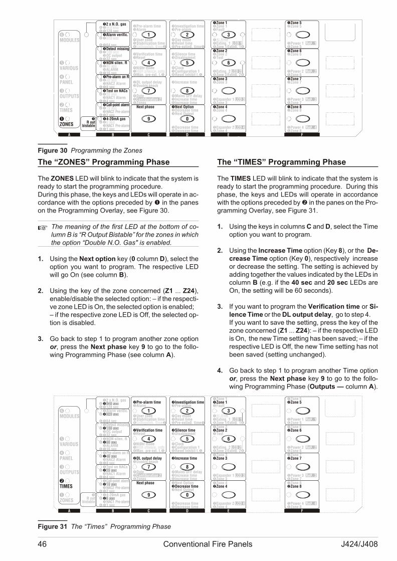
The “ZONES” Programming Phase
The ZONES LED will blink to in di ca te that the system isre ady to start the pro gram ming pro ce du re. Du ring this pha se, the keys and LEDs will ope ra te in ac -cor dan ce with the op tions pre ce ded by � in the pa neson the Pro gram ming Over lay, see Fi gu re 30.
+ The me a ning of the first LED at the bot tom of co -lumn B is “R Out put Bi sta ble” for the zo nes in which the op tion “Do u ble N.O. Gas" is ena bled.
1. Using the Next op tion key (0 co lumn D), se lect theop tion you want to pro gram. The re spec ti ve LEDwill go On (see co lumn B).
2. Using the key of the zone con cer ned (Z1 ... Z24),ena ble/di sa ble the se lec ted op tion: – if the re spec ti -ve zone LED is On, the se lec ted op tion is ena bled;– if the re spec ti ve zone LED is Off, the se lec ted op -tion is di sa bled.
3. Go back to step 1 to pro gram anot her zone op tionor, press the Next pha se key 9 to go to the fol lo -wing Pro gram ming Pha se (see co lumn A).
The “TIMES” Programming Phase
The TIMES LED will blink to in di ca te that the system isre ady to start the pro gram ming pro ce du re. Du ring thispha se, the keys and LEDs will ope ra te in ac cor dan cewith the op tions pre ce ded by � in the pa nes on the Pro -gram ming Over lay, see Fi gu re 31.
1. Using the keys in co lumns C and D, se lect the Timeop tion you want to pro gram.
2. Using the Incre a se Time op tion (Key 8), or the De -cre a se Time op tion (Key 0), re spec ti vely in cre a seor de cre a se the set ting. The set ting is achie ved byad ding to get her the va lu es in di ca ted by the LEDs in co lumn B (e.g. if the 40 sec and 20 sec LEDs areOn, the set ting will be 60 se conds).
3. If you want to pro gram the Ve ri fi ca tion time or Si -len ce Time or the DL out put de lay, go to step 4. If you want to save the set ting, press the key of thezone con cer ned (Z1 ... Z24): – if the re spec ti ve LED is On, the new Time set ting has been sa ved; – if the re spec ti ve LED is Off, the new Time set ting has notbeen sa ved (set ting un chan ged).
4. Go back to step 1 to pro gram anot her Time op tionor, press the Next pha se key 9 to go to the fol lo -wing Pro gram ming Pha se (Out puts — co lumn A).
46 Conventional Fire Panels J424/J408
�-
gConfi uration 2
�DL output delay�Double knock
�Date��Zones
MM�M
�
�
MM�M
�
�
MM�M
�
�
MM�M
�
�
MM�M
�
�
MM�M
�
�
MM�M
�
�
M�MM��
�4-20mA gas��N�1 sec
�C
N���2 sec
�Test on NACs��NAC1 Alarm�4 sec
�
�NAC2 Alarm�8 sec
�NON silen. R��ALARM�16 sec
���OC output�32 sec
��128 sec
�2 x N.O. gas
MODULES
VARIOUS
PANEL
OUTPUTS
TIMES
ZONES
�-�Investigation time�Pre-alarm
�Day mode�Reset time
g�Pre-extin . time�
�Zone 1�Zone 1�Fault
��Exting. 1 LCD 1
�Zone 5�Zone 5
�Power 1 pRe . 1�Zone 5
�Zone 2�Zone 2�Test
�Exting. 2 LCD 2
�Zone 6�Zone 6
�Power 2 pRe . 2�Zone 6
�Zone 3�Zone 3
�Expander 1 LCD 3�Zone 3
�Zone 7�Zone 7
�Power 3 pRe . 3�Zone 7
�Zone 4�Zone 4
�Expander 2 LCD 4�Zone 4
�Zone 8�Zone 8
�Power 4 pRe . 4�Zone 8
�
g Zone 2/Extin . 2� �
�-�Verification time�Reset
g�Ni ht mode��Man. pre-ext. t.�
�-�Pre-alarm time�Alarm
�User code�Stabilization time� �
�-�Silence time�Disablement
�Clock�Configuration 1�Reset Inhibit t.�
1 2 3
4 5 6
7 8
9 0
�Next Option�Decrease time�Next Output
�Decrease time�Decrease time
�-�Increase time
�Mains OFF delay�Increase time�Increase time
�Next phase
CBA E FD
Pre-alarm on R
Detect missing
Call-point alarm
NAC2 Pre-alarm
NAC1 Pre-alarm
gZone 1/Extin . 1�
�R out
bistable
�Alarm verific.�
�64 sec
�
Fi gu re 30 Pro gram ming the Zo nes
MM�M
�
�
MM�M
�
�
MM�M
�
�
MM�M
�
�
MM�M
�
�
MM�M
�
�
MM�M
�
�
M�MM��
�4-20mA gas�5 sec5 sec�N�1 sec
�C�10 sec10 sec�N�2 sec
�Test on NACs�20 sec20 sec�NAC1 Alarm�4 sec
��40 sec40 sec�NAC2 Alarm�8 sec
�NON silen. R�80 sec80 sec�ALARM�16 sec
��160 sec160 sec�OC output�32 sec
�Alarm verific.�320 sec320 sec
�64 sec
�2 x N.O. gas�640 sec640 sec�128 sec
MODULES
VARIOUS
PANEL
OUTPUTS
TIMES
ZONES
�-�Investigation time�Pre-alarm
�Day mode�Reset time
g�Pre-extin . time�
�Zone 1�Zone 1�Fault
�ALARMALARM�Exting. 1 LCD 1
�Zone 5�Zone 5
�Power 1 pRe . 1�Zone 5
�Zone 2�Zone 2�Test
�Exting. 2 LCD 2
�Zone 6�Zone 6
�Power 2 pRe . 2�Zone 6
�Zone 3�Zone 3
�Expander 1 LCD 3�Zone 3
�Zone 7�Zone 7
�Power 3 pRe . 3�Zone 7
�Zone 4�Zone 4
�Expander 2 LCD 4�Zone 4
�Zone 8�Zone 8
�Power 4 pRe . 4�Zone 8
�
g Zone 2/Extin . 2� �
�-�Verification time�Reset
g�Ni ht mode�NON silence. outsNON silence. outs�Man. pre-ext. t.�
�-�Pre-alarm time�Alarm
�User code�Stabilization time� �Extinguish. timeExtinguish. time
�-�Silence time�Disablement
�Clock�Configuration 1�Reset Inhibit t.�
�-
gConfi uration 2
�DL output delay�Double knock
�Date��Zones
1 2 3
4 5 6
7 8
9 0
�Next Option�Decrease time�Next Output
�Decrease time�Decrease time
�-�Increase time
�Mains OFF delay�Increase time�Increase time
�Next phase
CBA E FD
Pre-alarm on R
Detect missing
Call-point alarm
NAC2 Pre-alarm
NAC1 Pre-alarm
gZone 1/Extin . 1�
�R out
bistable
Fi gu re 31 The “Ti mes” Pro gram ming Pha se
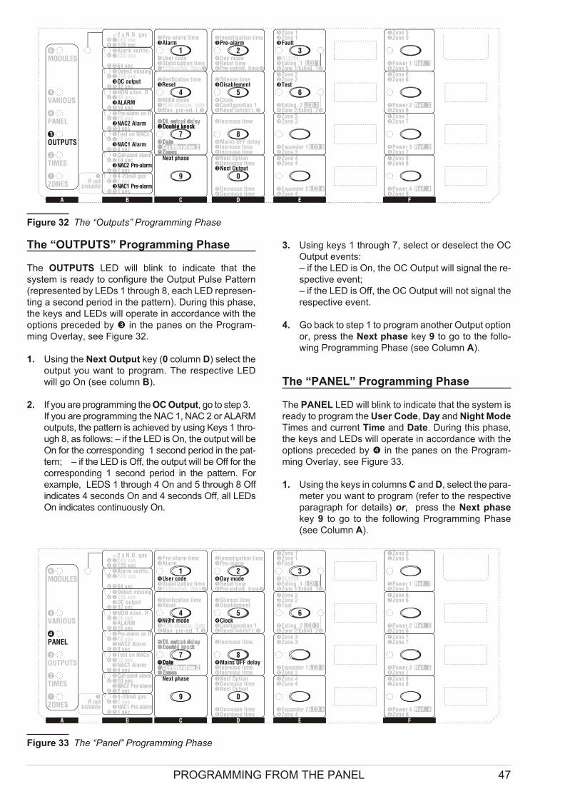
The “OUTPUTS” Programming Phase
The OUTPUTS LED will blink to in di ca te that thesystem is re ady to con fi gu re the Out put Pul se Pat tern(re pre sen ted by LEDs 1 thro ugh 8, each LED re pre sen -ting a se cond pe riod in the pat tern). Du ring this pha se,the keys and LEDs will ope ra te in ac cor dan ce with theop tions pre ce ded by � in the pa nes on the Pro gram -ming Over lay, see Fi gu re 32.
1. Using the Next Out put key (0 co lumn D) se lect theout put you want to pro gram. The re spec ti ve LEDwill go On (see co lumn B).
2. If you are pro gram ming the OC Out put, go to step 3.If you are pro gram ming the NAC 1, NAC 2 or ALARMout puts, the pat tern is achie ved by using Keys 1 thro -ugh 8, as fol lows: – if the LED is On, the out put will beOn for the cor re spon ding 1 se cond pe riod in the pat -tern; – if the LED is Off, the out put will be Off for thecor re spon ding 1 se cond pe riod in the pat tern. Forexam ple, LEDS 1 thro ugh 4 On and 5 thro ugh 8 Offin di ca tes 4 se conds On and 4 se conds Off, all LEDsOn in di ca tes con ti nu o usly On.
3. Using keys 1 thro ugh 7, se lect or de se lect the OCOut put events:– if the LED is On, the OC Out put will si gnal the re -spec ti ve event;– if the LED is Off, the OC Out put will not si gnal there spec ti ve event.
4. Go back to step 1 to pro gram anot her Out put op tion or, press the Next pha se key 9 to go to the fol lo -wing Pro gram ming Pha se (see Co lumn A).
The “PANEL” Programming Phase
The PANEL LED will blink to in di ca te that the system isre ady to pro gram the User Code, Day and Night ModeTi mes and cur rent Time and Date. Du ring this pha se,the keys and LEDs will ope ra te in ac cor dan ce with theop tions pre ce ded by � in the pa nes on the Pro gram -ming Over lay, see Fi gu re 33.
1. Using the keys in co lumns C and D, se lect the pa ra -me ter you want to pro gram (re fer to the re spec ti vepa ra graph for de ta ils) or, press the Next pha sekey 9 to go to the fol lo wing Pro gram ming Pha se(see Co lumn A).
PROGRAMMING FROM THE PANEL 47
MM�M
�
�
MM�M
�
�
MM�M
�
�
MM�M
�
�
MM�M
�
�
MM�M
�
�
MM�M
�
�
M�MM��
�4-20mA gas
�N�1 sec
�C�10 sec
N�2 sec�
�Test on NACs
�NAC1 Alarm�4 sec
�
�NAC2 Alarm�8 sec
�NON silen. R
�ALARM�16 sec
�
�OC output�32 sec
�Alarm verific.
�64 sec
?2 x N.O. gas
�128 sec
MODULES
VARIOUS
PANEL
OUTPUTS
TIMES
ZONES
�-�Investigation time�Pre-alarm
�Day mode�Reset time
g�Pre-extin . time�
�Zone 1�Zone 1�Fault
�Exting. 1 LCD 1
�Zone 5�Zone 5
�Power 1 pRe . 1�Zone 5
�Zone 2�Zone 2�Test
�Exting. 2 LCD 2
�Zone 6�Zone 6
�Power 2 pRe . 2�Zone 6
�Zone 3�Zone 3
�Expander 1 LCD 3�Zone 3
�Zone 7�Zone 7
�Power 3 pRe . 3�Zone 7
�Zone 4�Zone 4
�Expander 2 LCD 4�Zone 4
�Zone 8�Zone 8
�Power 4 pRe . 4�Zone 8
�
g Zone 2/Extin . 2� �
�-�Verification time�Reset
g�Ni ht mode
�Man. pre-ext. t.�
�-�Pre-alarm time�Alarm
�User code�Stabilization time
�-�Silence time�Disablement
�Clock�Configuration 1�Reset Inhibit t.�
�-
gConfi uration 2
�DL output delay�Double knock
�Date��Zones
�-�DL output delay�Double knock
�Date� gConfi uration 2�Zones
1 2 3
4 5 6
7 8
9 0
�Next Option�Decrease time�Next Output
�Decrease time�Decrease time
�-�Increase time
�Mains OFF delay�Increase time�Increase time
�Next phase
CBA E FD
Pre-alarm on R
Detect missing
Call-point alarm
NAC2 Pre-alarm
NAC1 Pre-alarm
gZone 1/Extin . 1�
�R out
bistable
Fi gu re 32 The “Out puts” Pro gram ming Pha se
MM�M
�
�
MM�M
�
�
MM�M
�
�
MM�M
�
�
MM�M
�
�
MM�M
�
�
MM�M
�
�
M�MM��
�4-20mA gas�5 sec�5 sec�N�1 sec
�C�10 sec�N�2 sec
�C�10 sec�N�2 sec
�Test on NACs�20 sec�20 sec�NAC1 Alarm�4 sec
��40 sec�40 sec�NAC2 Alarm�8 sec
�NON silen. R�80 sec�80 sec�ALARM�16 sec
��160 sec�160 sec�OC output�32 sec
�Alarm verific.�320 sec�320 sec
�64 sec
?2 x N.O. gas�640 sec�640 sec�128 sec
MODULES
VARIOUS
PANEL
OUTPUTS
TIMES
ZONES
�-�Investigation time�Pre-alarm
�Day mode�Reset time
g�Pre-extin . time�
�Zone 1�Zone 1�Fault
�ALARM�ALARM�Exting. 1 LCD 1
�Zone 5�Zone 5
�Power 1 pRe . 1�Zone 5
�Zone 2�Zone 2�Test
�Exting. 2 LCD 2
�Zone 6�Zone 6
�Power 2 pRe . 2�Zone 6
�Zone 3�Zone 3
�Expander 1 LCD 3�Zone 3
�Zone 7�Zone 7
�Power 3 pRe . 3�Zone 7
�Zone 4�Zone 4
�Expander 2 LCD 4�Zone 4
�Zone 8�Zone 8
�Power 4 pRe . 4�Zone 8
�
g Zone 2/Extin . 2� �
�-�Verification time�Reset
g�Ni ht mode�NON silence. Outs�NON silence. Outs�Man. pre-ext. T.�
�-�Pre-alarm time�Alarm
�User code�Stabilization time� �Extinguish. time�Extinguish. time�
�-�Silence time�Disablement
�Clock�Configuration 1�Reset Inhibit t.�
�-
gConfi uration 2
�DL output delay�Double knock
�Date��Zones
�-�DL output delay�Double knock
�Date� gConfi uration 2�Zones
1 2 3
4 5 6
7 8
9 0
�Next Option�Decrease time�Next Output
�Decrease time�Decrease time
�-�Increase time
�Mains OFF delay�Increase time�Increase time
�Next phase
CBA E FD
Pre-alarm on R
Detect missing
Call-point alarm
NAC2 Pre-alarm
NAC1 Pre-alarm
gZone 1/Extin . 1�
�R out
bistable
Fi gu re 33 The “Pa nel” Pro gram ming Phase
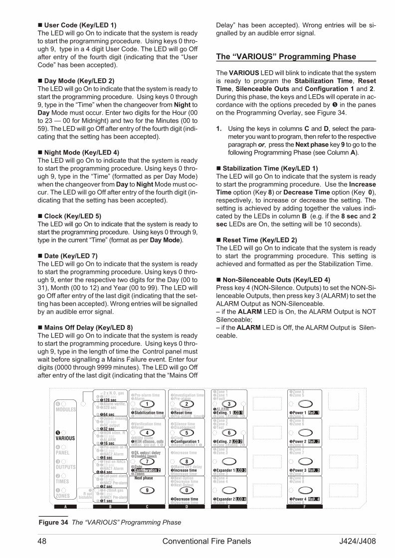
n User Code (Key/LED 1)The LED will go On to in di ca te that the system is re adyto start the pro gram ming pro ce du re. Using keys 0 thro -ugh 9, type in a 4 di git User Code. The LED will go Offaf ter entry of the fo urth di git (in di ca ting that the “UserCode” has been ac cep ted).
n Day Mode (Key/LED 2)The LED will go On to in di ca te that the system is re ady to start the pro gram ming pro ce du re. Using keys 0 thro ugh9, type in the “Time” when the chan ge o ver from Night toDay Mode must oc cur. Enter two di gits for the Hour (00to 23 — 00 for Mid night) and two for the Mi nu tes (00 to59). The LED will go Off af ter entry of the fo urth di git (in di -ca ting that the set ting has been ac cep ted).
n Night Mode (Key/LED 4)The LED will go On to in di ca te that the system is re adyto start the pro gram ming pro ce du re. Using keys 0 thro -ugh 9, type in the “Time” (for mat ted as per Day Mode)when the chan ge o ver from Day to Night Mode must oc -cur. The LED will go Off af ter entry of the fo urth di git (in -di ca ting that the set ting has been ac cep ted).
n Clock (Key/LED 5)The LED will go On to in di ca te that the system is re ady tostart the pro gram ming pro ce du re. Using keys 0 thro ugh 9,type in the cur rent “Time” (for mat as per Day Mode).
n Date (Key/LED 7)The LED will go On to in di ca te that the system is re adyto start the pro gram ming pro ce du re. Using keys 0 thro -ugh 9, en ter the re spec ti ve two di gits for the Day (00 to31), Month (00 to 12) and Year (00 to 99). The LED willgo Off af ter entry of the last di git (in di ca ting that the set -ting has been ac cep ted). Wrong en tries will be si gnal led by an au di ble er ror si gnal.
n Mains Off Delay (Key/LED 8)The LED will go On to in di ca te that the system is re adyto start the pro gram ming pro ce du re. Using keys 0 thro -ugh 9, type in the length of time the Con trol pa nel mustwait be fo re si gnal ling a Ma ins Fa i lu re event. Enter fourdi gits (0000 thro ugh 9999 mi nu tes). The LED will go Offaf ter entry of the last di git (in di ca ting that the “Ma ins Off
De lay” has been ac cep ted). Wrong en tries will be si -gnal led by an au di ble er ror si gnal.
The “VARIOUS” Programming Phase
The VARIOUS LED will blink to in di ca te that the systemis re ady to pro gram the Sta bi li za tion Time, Re setTime, Si len ce a ble Outs and Con fi gu ra tion 1 and 2. Du ring this pha se, the keys and LEDs will ope ra te in ac -cor dan ce with the op tions pre ce ded by � in the pa neson the Pro gram ming Over lay, see Fi gu re 34.
1. Using the keys in co lumns C and D, se lect the pa ra -me ter you want to pro gram, then re fer to the re spec ti ve pa ra graph or, press the Next pha se key 9 to go to thefol lo wing Pro gram ming Pha se (see Co lumn A).
n Stabilization Time (Key/LED 1)The LED will go On to in di ca te that the system is re adyto start the pro gram ming pro ce du re. Use the Incre a seTime op tion (Key 8) or De cre a se Time op tion (Key 0),re spec ti vely, to in cre a se or de cre a se the set ting. Theset ting is achie ved by ad ding to get her the va lu es in di -ca ted by the LEDs in co lumn B (e.g. if the 8 sec and 2sec LEDs are On, the set ting will be 10 se conds).
n Reset Time (Key/LED 2)The LED will go On to in di ca te that the system is re adyto start the pro gram ming pro ce du re. This set ting isachie ved and for mat ted as per the Sta bi li za tion Time.
n Non-Silenceable Outs (Key/LED 4)Press key 4 (NON-Si len ce. Out puts) to set the NON-Si -len ce a ble Out puts, then press key 3 (ALARM) to set the ALARM Out put as NON-Si len ce a ble.– if the ALARM LED is On, the ALARM Out put is NOTSi len ce a ble;– if the ALARM LED is Off, the ALARM Out put is Si len -ce a ble.
48 Conventional Fire Panels J424/J408
MM�M
�
�
MM�M
�
�
�
MM�M
�
MM�M
�
�
MM�M
�
�
MM�M
�
�
MM�M
�
�
M�MM��
�4-20mA gas�5 sec�5 sec�N�1 sec
���
C
N�2 sec
10 sec10 sec
�Test on NACs�20 sec�20 sec�NAC1 Alarm�4 sec
��40 sec�40 sec�NAC2 Alarm�8 sec
�NON silen. R�80 sec�80 sec�ALARM�16 sec
��160 sec�160 sec�OC output�32 sec
�Alarm verific.�320 sec
�64 sec
320 sec
?2 x N.O. gas�640 sec�640 sec�128 sec
MODULES
VARIOUS
PANEL
OUTPUTS
TIMES
ZONES
�-�Investigation time�Pre-alarm
�Day mode�Reset time
g�Pre-extin . time�
�Zone 1�Zone 1�Fault
�ALARMALARM�Exting. 1 LCD 1
�Zone 5�Zone 5
�Power 1 pRe . 1�Zone 5
�Zone 2�Zone 2�Test
�Exting. 2 LCD 2
�Zone 6�Zone 6
�Power 2 pRe . 2�Zone 6
�Zone 3�Zone 3
�Expander 1 LCD 3�Zone 3
�Zone 7�Zone 7
�Power 3 pRe . 3�Zone 7
�Zone 4�Zone 4
�Expander 2 LCD 4�Zone 4
�Zone 8�Zone 8
�Power 4 pRe . 4�Zone 8
�
g Zone 2/Extin . 2� �
�-�Verification time�Reset
g�Ni ht mode�NON silence. outsNON silence. outs�Man. pre-ext. t.�
�-�Pre-alarm time�Alarm
�User code�Stabilization time� �Extinguish. time�Extinguish. time�
�-�Silence time�Disablement
�Clock�Configuration 1�Reset Inhibit t.�
�-
gConfi uration 2
�DL output delay�Double knock
�Date��Zones
�-�DL output delay�Double knock
�Date� gConfi uration 2�Zones
1 2 3
4 5 6
7 8
9 0
�Next Option�Decrease time�Next Output
�Decrease time�Decrease time
�-�Increase time
�Mains OFF delay�Increase time�Increase time
�Next phase
CBA E FD
Pre-alarm on R
Detect missing
Call-point alarm
NAC2 Pre-alarm
NAC1 Pre-alarm
gZone 1/Extin . 1�
�R out
bistable
Fi gu re 34 The “VARIOUS” Pro gram ming Phase
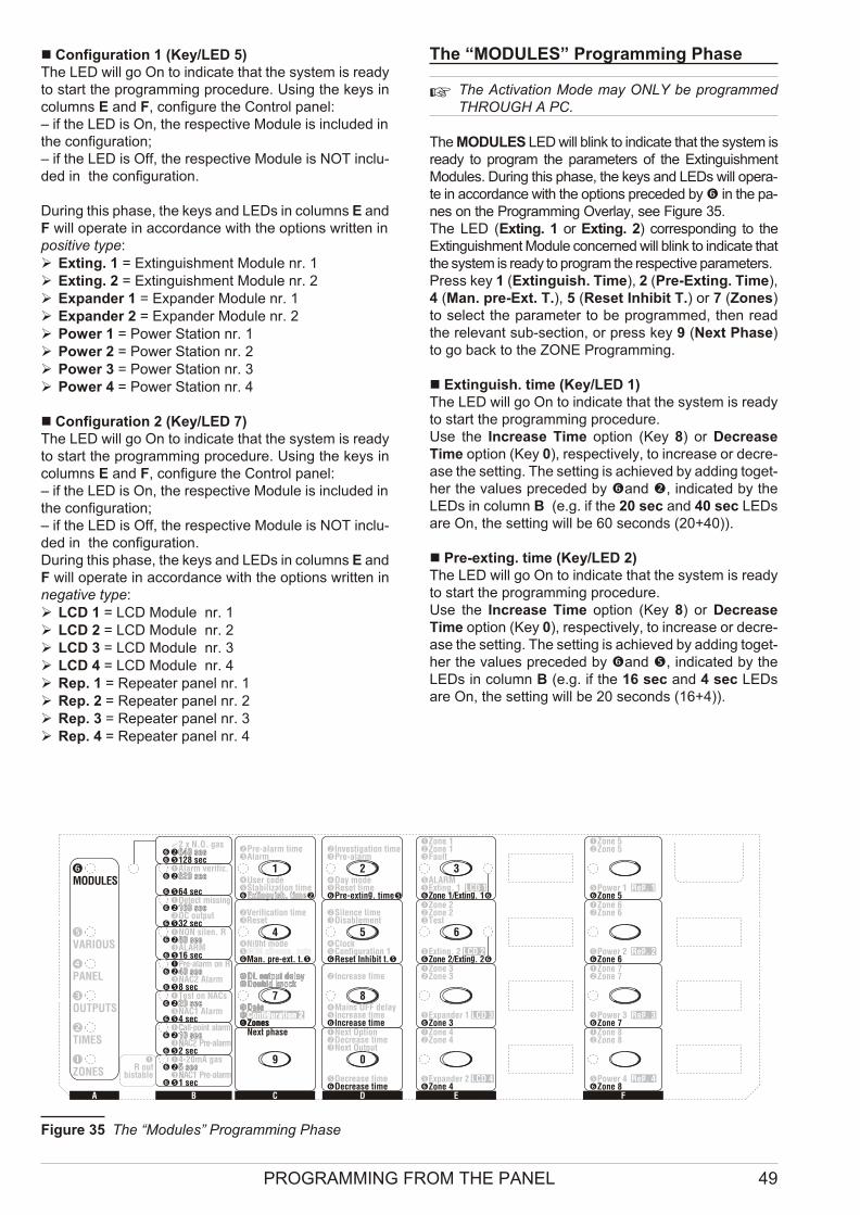
n Configuration 1 (Key/LED 5)The LED will go On to in di ca te that the system is re adyto start the pro gram ming pro ce du re. Using the keys inco lumns E and F, con fi gu re the Con trol pa nel:– if the LED is On, the re spec ti ve Mo du le is in clu ded in the con fi gu ra tion; – if the LED is Off, the re spec ti ve Mo du le is NOT in clu -ded in the con fi gu ra tion.
Du ring this pha se, the keys and LEDs in co lumns E andF will ope ra te in ac cor dan ce with the op tions writ ten in po si ti ve type:Ø Exting. 1 = Extin gui shment Mo du le nr. 1Ø Exting. 2 = Extin gui shment Mo du le nr. 2Ø Expan der 1 = Expan der Mo du le nr. 1Ø Expan der 2 = Expan der Mo du le nr. 2Ø Po wer 1 = Po wer Sta tion nr. 1Ø Po wer 2 = Po wer Sta tion nr. 2Ø Po wer 3 = Po wer Sta tion nr. 3Ø Po wer 4 = Po wer Sta tion nr. 4
n Configuration 2 (Key/LED 7)The LED will go On to in di ca te that the system is re adyto start the pro gram ming pro ce du re. Using the keys inco lumns E and F, con fi gu re the Con trol pa nel:– if the LED is On, the re spec ti ve Mo du le is in clu ded in the con fi gu ra tion; – if the LED is Off, the re spec ti ve Mo du le is NOT in clu -ded in the con fi gu ra tion. Du ring this pha se, the keys and LEDs in co lumns E andF will ope ra te in ac cor dan ce with the op tions writ ten inne ga ti ve type:Ø LCD 1 = LCD Mo du le nr. 1Ø LCD 2 = LCD Mo du le nr. 2Ø LCD 3 = LCD Mo du le nr. 3Ø LCD 4 = LCD Mo du le nr. 4Ø Rep. 1 = Re pe a ter pa nel nr. 1Ø Rep. 2 = Re pe a ter pa nel nr. 2Ø Rep. 3 = Re pe a ter pa nel nr. 3Ø Rep. 4 = Re pe a ter pa nel nr. 4
The “MODULES” Programming Phase
+ The Acti va tion Mode may ONLY be pro gram medTHROUGH A PC.
The MODULES LED will blink to in di ca te that the system isre ady to pro gram the pa ra me ters of the Extin gui shmentMo du les. Du ring this pha se, the keys and LEDs will ope ra -te in ac cor dan ce with the op tions pre ce ded by � in the pa -nes on the Pro gram ming Over lay, see Fi gu re 35. The LED (Exting. 1 or Exting. 2) cor re spon ding to theExtin gui shment Mo du le con cer ned will blink to in di ca te that the system is re ady to pro gram the re spec ti ve pa ra me ters.Press key 1 (Extin guish. Time), 2 (Pre-Exting. Time),4 (Man. pre-Ext. T.), 5 (Re set Inhi bit T.) or 7 (Zo nes)to se lect the pa ra me ter to be pro gram med, then readthe re le vant sub-sec tion, or press key 9 (Next Pha se)to go back to the ZONE Pro gram ming.
n Extin guish. time (Key/LED 1)The LED will go On to in di ca te that the system is re adyto start the pro gram ming pro ce du re. Use the Incre a se Time op tion (Key 8) or De cre a seTime op tion (Key 0), re spec ti vely, to in cre a se or de cre -a se the set ting. The set ting is achie ved by ad ding to get -her the va lu es pre ce ded by �and �, in di ca ted by theLEDs in co lumn B (e.g. if the 20 sec and 40 sec LEDsare On, the set ting will be 60 se conds (20+40)).
n Pre-exting. time (Key/LED 2)The LED will go On to in di ca te that the system is re adyto start the pro gram ming pro ce du re. Use the Incre a se Time op tion (Key 8) or De cre a seTime op tion (Key 0), re spec ti vely, to in cre a se or de cre -a se the set ting. The set ting is achie ved by ad ding to get -her the va lu es pre ce ded by �and �, in di ca ted by theLEDs in co lumn B (e.g. if the 16 sec and 4 sec LEDsare On, the set ting will be 20 se conds (16+4)).
PROGRAMMING FROM THE PANEL 49
�
�
MM�M
�
�
MM�M
�
�
MM�M
�
�
MM�M
�
�
MM�M
�
�
MM�M
�
�
MM�M
��
M�MM
�4-20mA gas�5 sec5 sec�N�1 sec
�C�10 sec10 sec�N�2 sec
�Test on NACs�20 sec20 sec�NAC1 Alarm�4 sec
��40 sec40 sec�NAC2 Alarm�8 sec
�NON silen. R�80 sec80 sec�ALARM�16 sec
��160 sec160 sec�OC output�32 sec
�Alarm verific.�320 sec320 sec
�64 sec
?2 x N.O. gas�640 sec�640 sec�128 sec
MODULES
VARIOUS
PANEL
OUTPUTS
TIMES
ZONES
�-�Investigation time�Pre-alarm
�Day mode�Reset time
g�Pre-extin . time�
�Zone 1�Zone 1�Fault
�ALARM�Exting. 1 LCD 1
�Zone 5�Zone 5
�Power 1 pRe . 1�Zone 5
�Zone 2�Zone 2�Test
�Exting. 2 LCD 2
�Zone 6�Zone 6
�Power 2 pRe . 2�Zone 6
�Zone 3�Zone 3
�Expander 1 LCD 3�Zone 3
�Zone 7�Zone 7
�Power 3 pRe . 3�Zone 7
�Zone 4�Zone 4
�Expander 2 LCD 4�Zone 4
�Zone 8�Zone 8
�Power 4 pRe . 4�Zone 8
�
g Zone 2/Extin . 2� �
�-�Verification time�Reset
g�Ni ht mode�NNOON N silence. silence. outsouts�Man. pre-ext. t.�
�-�Pre-alarm time�Alarm
�User code�Stabilization time�Extinguish. Extinguish. time�time
�-�Silence time�Disablement
�Clock�Configuration 1�Reset Inhibit t.�
�-
gConfi uration 2
�DL output delay�Double knock
�Date��Zones
�-�DL output delay�Double knock
�Date� gConfi uration 2�Zones
1 2 3
4 5 6
7 8
9 0
�Next Option�Decrease time�Next Output
�Decrease time�Decrease time
�-�Increase time
�Mains OFF delay�Increase time�Increase time
�Next phase
CBA E FD
Pre-alarm on R
Detect missing
Call-point alarm
NAC2 Pre-alarm
NAC1 Pre-alarm
gZone 1/Extin . 1�
�R out
bistable
Fi gu re 35 The “Mo du les” Pro gram ming Phase
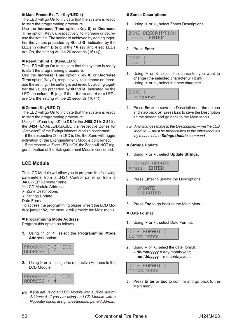
n Man. Preest-Ex. T. (Key/LED 4)The LED will go On to in di ca te that the system is re adyto start the pro gram ming pro ce du re. Use the Incre a se Time op tion (Key 8) or De cre a seTime op tion (Key 0), re spec ti vely, to in cre a se or de cre -a se the set ting. The set ting is achie ved by ad ding to get -her the va lu es pre ce ded by �and �, in di ca ted by theLEDs in co lumn B (e.g. if the 16 sec and 4 sec LEDsare On, the set ting will be 20 se conds (16+4)).
n Reset Inhibit T. (Key/LED 5)The LED will go On to in di ca te that the system is re adyto start the pro gram ming pro ce du re. Use the Incre a se Time op tion (Key 8) or De cre a seTime op tion (Key 0), re spec ti vely, to in cre a se or de cre -a se the set ting. The set ting is achie ved by ad ding to get -her the va lu es pre ce ded by �and �, in di ca ted by theLEDs in co lumn B (e.g. if the 16 sec and 4 sec LEDsare On, the set ting will be 20 se conds (16+4)).
n Zones (Key/LED 7)The LED will go On to in di ca te that the system is re adyto start the pro gram ming pro ce du re. Using the Zone keys (Z1 to Z 8 for the J408; Z1 to Z 24 forthe J424) ENABLE/DISABLE the re spec ti ve Zo nes for“Acti va tion” of the Extin gui shment Mo du le con cer ned:– if the re spec ti ve Zone LED is On, the Zone will trig gerac ti va tion of the Extin gui shment Mo du le con cer ned;– if the re spec ti ve Zone LED is Off, the Zone will NOT trig -ger ac ti va tion of the Extin gui shment Mo du le con cer ned.
LCD Module
The LCD Mo du le will al low you to pro gram the fol lo wingpa ra me ters from a J424 Con trol pa nel or from aJ400-REP Re pe a ter pa nel:Ø LCD Mo du le AddressØ Zone De scrip tionsØ Strings Upda teDate For matTo ac cess the pro gram ming pha se, in sert the LCD Mo -du le jum per 82, the mo du le will pro vi de the Main menu.
n Programming Mode AddressPro gram this op tion as fol lows.
1. Using Ú or Ù, se lect the Pro gram ming ModeAddress op tion:
PROGRAMMING MODE
ADDRESS : 1
2. Using Ø or ×, as sign the re spec ti ve Address to theLCD Mo du le.
PROGRAMMING MODE
ADDRESS : 4
+ If you are using an LCD Mo du le with a J424, as signAddress 4. If you are using an LCD Mo du le with aRe pe a ter pa nel, as sign the Re pe a ter pa nel Address.
n Zones Descriptions
1. Using Ú or Ù, se lect Zo nes De scrip tions:
ZONE DESCRIPTION
press ENTER
2. Press Enter:
ZONE 1
Zone 1
3. Using Ø or ×, se lect the cha rac ter you want tochan ge (the se lec ted cha rac ter will blink).Using Ú or Ù, se lect the new cha rac ter.
ZONE 1
Warehouse
4. Press Enter to save the De scrip tion on the scre enand step back or, press Esc to save the De scrip tionon the scre en and go back to the Main Menu.
+ Any chan ges made to the De scrip tions — via the LCD Mo du le — must be bro ad ca sted to the ot her Mo du lesby me ans of the Strings Upda te com mand.
n Strings Update
1. Using Ú or Ù, se lect Upda te Strings.
STRINGS UPDATE
press ENTER
2. Press Enter to up da te the De scrip tions.
UPDATE
EXECUTED
3. Press Esc to go back to the Main Menu..
n Date Format
1. Using Ú or Ù, se lect Date For mat:
DATE FORMAT :
dd/mm/yyyy
2. Using Ø or ×, se lect the date for mat:– dd/mm/yyyy = day/month/year;– mm/dd/yyyy = month/day/year.
DATE FORMAT :
mm/dd/yyyy
3. Press Enter or Esc to con firm and go back to theMain menu.
50 Conventional Fire Panels J424/J408
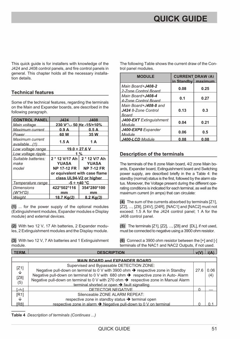
QUICK GUIDE
This quick gui de is for in stal lers with know led ge of theJ424 and J408 con trol pa nels, and fire con trol pa nels inge ne ral. This chap ter holds all the ne ces sary in stal la -tion de ta ils.
Technical features
Some of the tec hni cal fe a tu res, re gar ding the ter mi nalson the Main and Expan der bo ards, are de scri bed in thefol lo wing pa ra graph.
CONTROL PANEL J424 J408Main voltage 230 V~ 50 Hz -15/+10%Maximum current 0.9 A 0.5 APower 60 W 35 WMaximum currentavailable...(1)
1.5 A 1 A
Low voltage range 19.0 ÷ 27.6 VLow voltage ripple 1 %Suitable batteries:makemodel
2 * 12 V/17 AhYUASA
NP 17-12 FR
2 * 12 V/7 Ah YUASA
NP 7-12 FRor equivalent with case flame
class UL94-V2 or higherTemperature range -5 ÷ +40 °CDimensions(W*H*D)
422*502*116mm
354*280*100mm
Weight 18.7 Kg(2) 8.2 Kg(3)
(1) ... for the po wer supply of the op tio nal mo du les(Extin gui shment mo du les, Expan der mo du les e Di splay mo du le) and ex ter nal de vi ces.
(2) With two 12 V, 17 Ah bat te ries, 2 Expan der mo du -les, 2 Extin gui shment mo du les and the Di splay mo du le.
(3) With two 12 V, 7 Ah bat te ries and 1 Extin gui shmentmo du le.
The fol lo wing Ta ble shows the cur rent draw of the Con -trol pa nel mo du les.
MODULE CURRENT DRAW (A)in Standby maximum
Main Board+J408-22-Zone Control Board
0.08 0.25
Main Board+J408-44-Zone Control Board
0.1 0.27
Main Board+J408-8 andJ424 8-Zone ControlBoard
0.13 0.3
J400-EXT ExtinguishmentModule
0.04 0.21
J400-EXP8 ExpanderModule
0.06 0.5
J400-LCD Module 0.08 0.08
Description of the terminals
The ter mi nals of the 8 zone Main bo ard, 4/2 zone Main bo -ards, Expan der bo ard, Extin gui shment bo ard and Swit chingpo wer supply, are de scri bed briefly in the a Ta ble 4: thestandby (nor mal) sta tus is the first, fol lo wed by the alarm sta -tus. Mo re o ver, the Vol ta ge pre sent du ring the dif fe rent ope -ra ting con di tions is in di ca ted for each ter mi nal, as well as thema xi mum cur rent (in amps) that can cir cu la te:
(4) The sum of the cur rents ab sor bed by ter mi nals [Z1], [Z2], ..., [Z8], [24V], [24R], [NAC1] and [NAC2] must notex ce ed: 1.5 A for the J424 con trol pa nel; 1 A for theJ408 con trol pa nel.
(5) The ter mi nals [Z1], [Z2], ..., [Z8] and [DL], if not used,must be con nec ted to negative using a 3900 ohm re si stor.
(6) Con nect a 3900 ohm re si stor bet we en the [+] and [-]ter mi nals of the NAC1 and NAC2 Out puts, if not used.
QUICK GUIDE 51
TERM. DESCRIPTION v(V) i(A)
MAIN BOARD and EXPANDER BOARD
[Z1]â
[Z8](5)
Supervised and Bypassable DETECTION ZONE:Negative pull-down on terminal to 0 V with 3900 ohm è respective zone in Standby
Negative pull-down on terminal to 0 V with 680 ohm è respective zone in Auto- Alarm Negative pull-down on terminal to 0 V with 270 ohm è respective zone in Manual Alarm
terminal shorted or open è fault signalling
27.6
0.06(4)
[M] DETECTOR NEGATIVE 0 —[R1]â
[R8]
Silenceable ZONE ALARM REPEAT:respective zone in standby status è terminal open
respective zone in alarm è Negative pull-down to 0 V on terminal 0 0.1
Ta ble 4 De scrip tion of ter mi nals (Con ti nues ...)
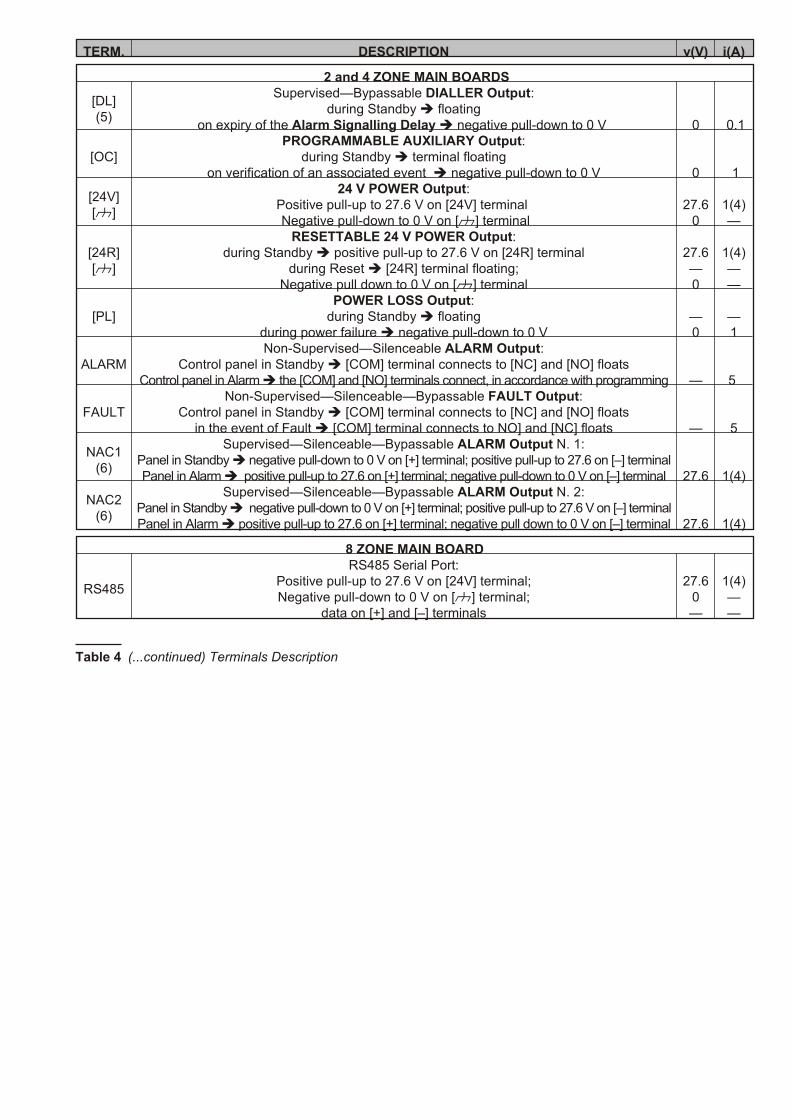
TERM. DESCRIPTION v(V) i(A)
2 and 4 ZONE MAIN BOARDS
[DL](5)
Supervised—Bypassable DIALLER Output:during Standby è floating
on expiry of the Alarm Signalling Delay è negative pull-down to 0 V 0 0.1
[OC]PROGRAMMABLE AUXILIARY Output:
during Standby è terminal floatingon verification of an associated event è negative pull-down to 0 V 0 1
[24V][M]
24 V POWER Output: Positive pull-up to 27.6 V on [24V] terminal Negative pull-down to 0 V on [M] terminal
27.60
1(4)—
[24R][M]
RESETTABLE 24 V POWER Output:during Standby è positive pull-up to 27.6 V on [24R] terminal
during Reset è [24R] terminal floating;Negative pull down to 0 V on [M] terminal
27.6—0
1(4)——
[PL]POWER LOSS Output:
during Standby è floatingduring power failure è negative pull-down to 0 V
—0
—1
ALARMNon-Supervised—Silenceable ALARM Output:
Control panel in Standby è [COM] terminal connects to [NC] and [NO] floatsControl panel in Alarm è the [COM] and [NO] terminals connect, in accordance with programming — 5
FAULTNon-Supervised—Silenceable—Bypassable FAULT Output:
Control panel in Standby è [COM] terminal connects to [NC] and [NO] floatsin the event of Fault è [COM] terminal connects to NO] and [NC] floats — 5
NAC1(6)
Supervised—Silenceable—Bypassable ALARM Output N. 1:Panel in Standby è negative pull-down to 0 V on [+] terminal; positive pull-up to 27.6 on [–] terminalPanel in Alarm è positive pull-up to 27.6 on [+] terminal; negative pull-down to 0 V on [–] terminal 27.6 1(4)
NAC2(6)
Supervised—Silenceable—Bypassable ALARM Output N. 2:Panel in Standby è negative pull-down to 0 V on [+] terminal; positive pull-up to 27.6 V on [–] terminalPanel in Alarm è positive pull-up to 27.6 on [+] terminal; negative pull down to 0 V on [–] terminal 27.6 1(4)
8 ZONE MAIN BOARD
RS485
RS485 Serial Port:Positive pull-up to 27.6 V on [24V] terminal;Negative pull-down to 0 V on [M] terminal;
data on [+] and [–] terminals
27.60—
1(4)——
Ta ble 4 (...continued) Ter mi nals De scrip tion
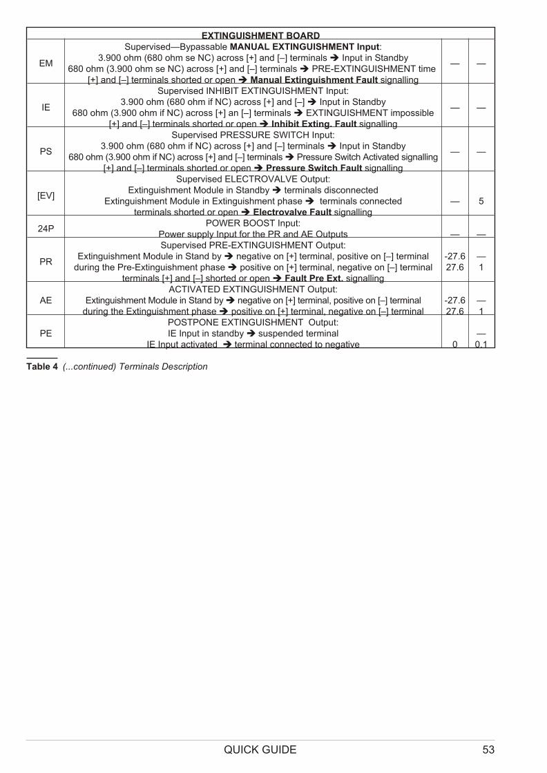
QUICK GUIDE 53
EXTINGUISHMENT BOARD
EM
Supervised—Bypassable MANUAL EXTINGUISHMENT Input:3.900 ohm (680 ohm se NC) across [+] and [–] terminals è Input in Standby
680 ohm (3.900 ohm se NC) across [+] and [–] terminals è PRE-EXTINGUISHMENT time [+] and [–] terminals shorted or open è Manual Extinguishment Fault signalling
— —
IE
Supervised INHIBIT EXTINGUISHMENT Input:3.900 ohm (680 ohm if NC) across [+] and [–] è Input in Standby
680 ohm (3.900 ohm if NC) across [+] an [–] terminals è EXTINGUISHMENT impossible[+] and [–] terminals shorted or open è Inhibit Exting. Fault signalling
— —
PS
Supervised PRESSURE SWITCH Input:3.900 ohm (680 ohm if NC) across [+] and [–] terminals è Input in Standby
680 ohm (3.900 ohm if NC) across [+] and [–] terminals è Pressure Switch Activated signalling[+] and [–] terminals shorted or open è Pressure Switch Fault signalling
— —
[EV]
Supervised ELECTROVALVE Output:Extinguishment Module in Standby è terminals disconnected
Extinguishment Module in Extinguishment phase è terminals connectedterminals shorted or open è Electrovalve Fault signalling
— 5
24PPOWER BOOST Input:
Power supply Input for the PR and AE Outputs — —
PR
Supervised PRE-EXTINGUISHMENT Output:Extinguishment Module in Stand by è negative on [+] terminal, positive on [–] terminal
during the Pre-Extinguishment phase è positive on [+] terminal, negative on [–] terminalterminals [+] and [–] shorted or open è Fault Pre Ext. signalling
-27.627.6
—1
AEACTIVATED EXTINGUISHMENT Output:
Extinguishment Module in Stand by è negative on [+] terminal, positive on [–] terminalduring the Extinguishment phase è positive on [+] terminal, negative on [–] terminal
-27.627.6
—1
PEPOSTPONE EXTINGUISHMENT Output:IE Input in standby è su spen ded ter mi nal
IE Input activated è terminal connected to negative 0—0.1
Ta ble 4 (...con ti nu ed) Ter mi nals De scrip tion

54 Conventional Fire Panels J424/J408

QUICK GUIDE 55

BENTEL SECURITY s.r.l.
Via Gabbiano, 22 – Zona Ind. S. Scolastica64013 Corropoli (TE) - ITALY
Tel.: +39 0861 839060
Fax: +39 0861 839065e-mail: [email protected]
http://www.bentelsecurity.com ISTISBLEJ408-8 1.0 280207 V10
®