Embed Size (px)
Citation preview
ISSN 1816-112X
Science Citation Index Expanded, Materials Science Citation Index and ISI Alerting
EDITORS-IN-CHIEF Asian Pacific, African and organizing Editor S.L. Chan The Hong Kong Polyt. Univ., Hong Kong American Editor W.F. Chen Univ. of Hawaii at Manoa, USA European Editor R. Zandonini Trento Univ., Italy INTERNATIONAL EDITORIAL BOARD F.G. Albermani The Univ. of Queensland, Australia I. Burgess Univ. of Sheffield, UK F.S.K. Bijlaard Delft Univ. of Technology, The Netherlands R. Bjorhovde The Bjorhovde Group, USA M.A. Bradford The Univ. of New South Wales, Australia D. Camotim Technical Univ. of Lisbon, Portugal C.M. Chan Hong Kong Univ. of Science & Technology, Hong Kong T.H.T. Chan Queensland Univ. of Technology, Australia S.P. Chiew Nanyang Technological Univ., Singapore W.K. Chow The Hong Kong Polyt. Univ., Hong Kong K.F. Chung The Hong Kong Polyt. Univ., Hong Kong G.G. Deierlein Standford Univ., California, USA
L. Dezi Univ. of Ancona, Italy D. Dubina The Politehnica Univ. of Timosoara, Romania R. Greiner Technical Univ. of Graz, Austria G.W.M. Ho Ove Arup & Partners Hong Kong Ltd., Hong Kong B.A. Izzuddin Imperial College of Science, Technology and Medicine, UK J.P. Jaspart Univ. of Liege, Belgium S. A. Jayachandran SERC, CSIR, Chennai, India S. Kitipornchai City Univ. of Hong Kong, Hong Kong D. Lam Univ. of Leeds, UK G.Q. Li Tongji Univ., China J.Y.R. Liew National Univ. of Singapore, Singapore X. Liu Tsinghua Univ., China E.M. Lui Syracuse Univ., USA Y.L. Mo Univ. of Houston, USA J.P. Muzeau CUST, Clermont Ferrand, France D.A. Nethercot Imperial College of Science, Technology and Medicine, UK Y.Q. Ni The Hong Kong Polyt. Univ., Hong Kong D.J. Oehlers The Univ. of Adelaide, Australia K. Rasmussen The Univ. of Sydney, Australia T.M. Roberts Cardiff Univ., UK
J.M. Rotter The Univ. of Edinburgh, UK C. Scawthorn Scawthorn Porter Associates, USA P. Schaumann Univ. of Hannover, Germany G.P. Shu Southeast Univ. China J.G. Teng The Hong Kong Polyt. Univ., Hong Kong G.S. Tong Zhejiang Univ., China K.C. Tsai National Taiwan Univ., Taiwan C.M. Uang Univ. of California, USA B. Uy University of Western Sydney M. Veljkovic Univ. of Lulea, Sweden F. Wald Czech Technical Univ. in Prague, Czech Y.C. Wang The Univ. of Manchester, UK Y.L. Xu The Hong Kong Polyt. Univ., Hong Kong D. White Georgia Institute of Technology, USA E. Yamaguchi Kyushu Institute of Technology, Japan Y.B. Yang National Taiwan Univ., Taiwan B. Young The Univ. of Hong Kong, Hong Kong X.L. Zhao Monash Univ., Australia
Z.H. Zhou Alpha Consultant Ltd., Hong Kong
Cover: Curved Roof of the New Wuhan Bullet Train Station in China

General Information Advanced Steel Construction, an international journal
Aims and scope The International Journal of Advanced Steel Construction provides a platform for the publication and rapid dissemination of original and up-to-date research and technological developments in steel construction, design and analysis. Scope of research papers published in this journal includes but is not limited to theoretical and experimental research on elements, assemblages, systems, material, design philosophy and codification, standards, fabrication, projects of innovative nature and computer techniques. The journal is specifically tailored to channel the exchange of technological know-how between researchers and practitioners. Contributions from all aspects related to the recent developments of advanced steel construction are welcome. Instructions to authors Submission of the manuscript. Authors may submit double-spaced manuscripts preferably in MS Word by emailing to one of the chief editors as follows for arrangement of review. Alternatively papers can be submitted on a diskette to one of the chief editors.
Asian Pacific , African and organizing editor : Professor S.L. Chan, Email: [email protected] American editor : Professor W.F. Chen, Email: [email protected] European editor : Professor R. Zandonini, Email: [email protected]
All manuscripts submitted to the journal are recommended to accompany with a list of four potential reviewers suggested by the author(s). This list should include the complete name, address, telephone and fax numbers, email address, and at least five keywords that identify the expertise of each reviewer. This scheme will improve the process of review. Style of manuscript General. Author(s) should provide full postal and email addresses and fax number for correspondence. The manuscript including abstract, keywords, references, figures and tables should be in English with pages numbered and typed with double line spacing on single side of A4 or letter-sized paper. The front page of the article should contain:
a) a short title (reflecting the content of the paper); b) all the name(s) and postal and email addresses of author(s) specifying the author to whom correspondence and proofs
should be sent; c) an abstract of 100-200 words; and d) 5 to 8 keywords.
The paper must contain an introduction and a conclusion. The length of paper should not exceed 25 journal pages (approximately 15,000 words equivalents). Tables and figures. Tables and figures including photographs should be typed, numbered consecutively in Arabic numerals and with short titles. They should be referred in the text as Figure 1, Table 2, etc. Originally drawn figures and photographs should be provided in a form suitable for photographic reproduction and reduction in the journal. Mathematical expressions and units. The Systeme Internationale (SI) should be followed whenever possible. The numbers identifying the displayed mathematical expression should be referred to in the text as Eq. (1), Eq. (2). References. References to published literature should be referred in the text, in the order of citation with Arabic numerals, by the last name(s) of the author(s) (e.g. Zandonini and Zanon [3]) or if more than three authors (e.g. Zandonini et al. [4]). References should be in English with occasional allowance of 1-2 exceptional references in local languages and reflect the current state-of-technology. Journal titles should be abbreviated in the style of the Word List of Scientific Periodicals. References should be cited in the following style [1, 2, 3]. Journal: [1] Chen, W.F. and Kishi, N., “Semi-rigid Steel Beam-to-column Connections, Data Base and Modelling”, Journal of
Structural Engineering, ASCE, 1989, Vol. 115, No. 1, pp. 105-119. Book: [2] Chan, S.L. and Chui, P.P.T., “Non-linear Static and Cyclic Analysis of Semi-rigid Steel Frames”, Elsevier Science,
2000. Proceedings: [3] Zandonini, R. and Zanon, P., “Experimental Analysis of Steel Beams with Semi-rigid Joints”, Proceedings of
International Conference on Advances in Steel Structures, Hong Kong, 1996, Vol. 1, pp. 356-364. Proofs. Proof will be sent to the corresponding author to correct any typesetting errors. Alternations to the original manuscript at this stage will not be accepted. Proofs should be returned within 48 hours of receipt by Express Mail, Fax or Email. Copyright. Submission of an article to “Advanced Steel Construction” implies that it presents the original and unpublished work, and not under consideration for publication nor published elsewhere. On acceptance of a manuscript submitted, the copyright thereof is transferred to the publisher by the Transfer of Copyright Agreement and upon the acceptance of publication for the papers, the corresponding author must sign the form for Transfer of Copyright. Permission. Quoting from this journal is granted provided that the customary acknowledgement is given to the source. Page charge and Reprints. There will be no page charges if the length of paper is within the limit of 25 journal pages. A total of 30 free offprints will be supplied free of charge to the corresponding author. Purchasing orders for additional offprints can be made on order forms which will be sent to the authors. These instructions can be obtained at the Hong Kong Institute of Steel Construction, Journal website: http://www.hkisc.org The International Journal of Advanced Steel Construction is published quarterly by non-profit making learnt society, The Hong Kong Institute of Steel Construction, c/o Department of Civil & Structural Engineering, The Hong Kong Polytechnic University, Hung Hom, Kowloon, Hong Kong.
Disclaimer. No responsibility is assumed for any injury and / or damage to persons or property as a matter of products liability, negligence or otherwise, or from any use or operation of any methods, products, instructions or ideas contained in the material herein. Subscription inquiries and change of address. Address all subscription inquiries and correspondence to Member Records, IJASC. Notify an address change as soon as possible. All communications should include both old and new addresses with zip codes and be accompanied by a mailing label from a recent issue. Allow six weeks for all changes to become effective. The Hong Kong Institute of Steel Construction HKISC c/o Department of Civil and Structural Engineering, The Hong Kong Polytechnic University, Hunghom, Kowloon, Hong Kong, China. Tel: 852- 2766 6047 Fax: 852- 2334 6389 Email: [email protected] Website: http://www.hkisc.org/ ISSN 1816-112X Science Citation Index Expanded, Materials Science Citation Index and ISI Alerting Copyright © 2010 by: The Hong Kong Institute of Steel Construction.
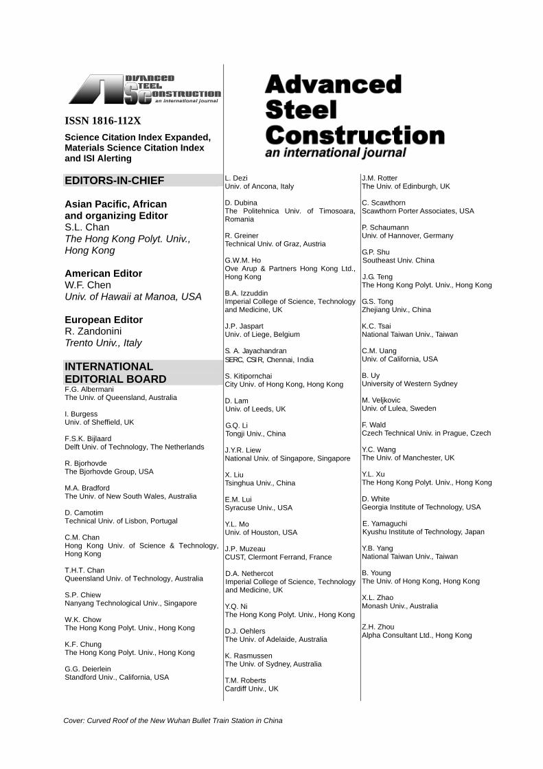
ISSN 1816-112X
Science Citation Index Expanded, Materials Science Citation Index and ISI Alerting
EDITORS-IN-CHIEF Asian Pacific, African and organizing Editor S.L. Chan The Hong Kong Polyt. Univ., Hong Kong Email: [email protected] American Editor W.F. Chen Univ. of Hawaii at Manoa, USA Email: [email protected] European Editor R. Zandonini Trento Univ., Italy Email: [email protected]
VOLUME 6 NUMBER 1 MARCH 2010
Technical Papers An Improved Effective Width Method Based on the 515 Theory of Plasticity Thomas Hansen, Jesper Gath and M.P. Nielsen An Assessment of Beam-to-Column Endplate and 548 Baseplate Joints Including the Axial-Moment Interaction A.A. Del Savio, D.A. Nethercot, P.C.G.S. Vellasco, L.R.O. de Lima and S.A.L. Andrade and L.F. Martha
Total Incremental Iterative Force Recovery Method and 567 the Application in Plastic Hinge Analysis of Steel Frames Fawu Wang and Yaopeng Liu Experimental Study of External Diaphragm Joint Connecting 578 CHS Column and H-Shaped Beam W.Q. Li, Y.Y. Chen, W. Wang, Y.J. Xu and X.D. Lv Development of An Engineering Methodology for 589 Thermal Analysis of Protected Structural Members in Fire Hong Liang, Stephen Welch and José L. Torero A Specific Procedure for Seismic Design of 603 Cold-Formed Steel Housing R. Landolfo, L. Fiorino and O. Iuorio Influence of Partial Loading on the Behaviour of 619 Pallet Rack Structures F. Al Qarud, A. Shatnawi, M.S. Abdel-Jaber and R.G. Beale Effects of Strain Regimes on the Behaviour of Headed 635 Stud Shear Connectors for Composite Steel-Concrete Beams O. Mirza and B. Uy An Investigation on the Post-Local-Buckling Analysis of 662 I-Section Struts Using Finite Strip Method H.R. Ovesy, J. Loughlan and S.A.M. Ghannadpour Conference Announcement
An assessment of beam-to-column endplate and baseplate joints including the axial-moment interaction
A.A. Del Savio (corresponding author) Civil Engineering Department, PUC-Rio – Pontifical Catholic University of Rio de Janeiro & Department of Civil and Environmental Engineering, Imperial College London Rua Marquês de São Vicente, 225, Gávea, Rio de Janeiro, RJ – Brazil, CEP: 22453-900 [email protected] Tel: +55 21 3527 1194; Fax: +55 21 3527 1195
D.A. Nethercot Department of Civil and Environmental Engineering, Imperial College London South Kensington Campus, Skempton Building, London SW7 2BU, United Kingdom [email protected] Tel: +44 20 7594 6097; Fax: +44 20 7594 6049
P.C.G.S. Vellasco & L.R.O. de Lima Structural Engineering Department, UERJ – State University of Rio de Janeiro Rua São Francisco Xavier, 524, Sala 5018A, Maracanã, Rio, RJ, Brazil, CEP: 20550-900 [email protected] & [email protected] Tel/Fax: +55 21 2587 7537
S.A.L. Andrade & L.F. Martha Civil Engineering Department, PUC-Rio – Pontifical Catholic University of Rio de Janeiro Rua Marquês de São Vicente, 225, Gávea, Rio de Janeiro, RJ – Brazil, CEP: 22453-900 [email protected] and [email protected] Tel: +55 21 3527 1188; Fax: +55 21 3527 1195
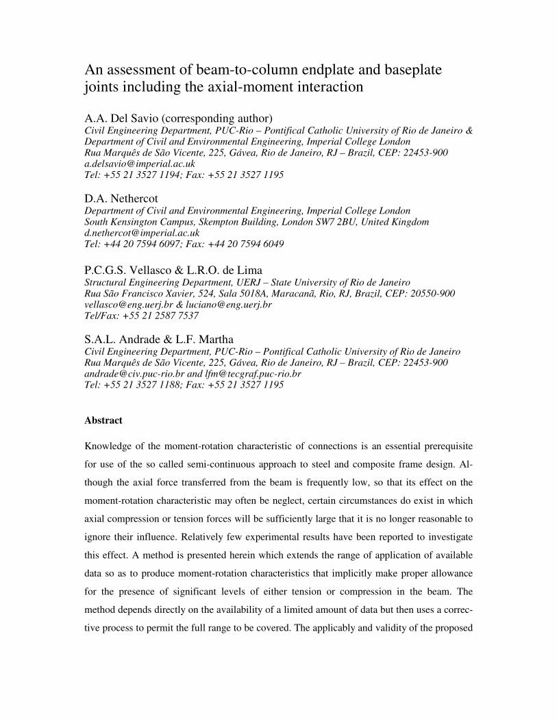
Abstract
Knowledge of the moment-rotation characteristic of connections is an essential prerequisite
for use of the so called semi-continuous approach to steel and composite frame design. Al-
though the axial force transferred from the beam is frequently low, so that its effect on the
moment-rotation characteristic may often be neglect, certain circumstances do exist in which
axial compression or tension forces will be sufficiently large that it is no longer reasonable to
ignore their influence. Relatively few experimental results have been reported to investigate
this effect. A method is presented herein which extends the range of application of available
data so as to produce moment-rotation characteristics that implicitly make proper allowance
for the presence of significant levels of either tension or compression in the beam. The
method depends directly on the availability of a limited amount of data but then uses a correc-
tive process to permit the full range to be covered. The applicably and validity of the proposed
methodology is demonstrated through comparisons against several tests on both flush end-
plate joints and base plate arrangements.
Keywords: axial versus bending moment interaction; joint behaviour; moment versus rotation
curves; rotational stiffness, semi-rigid joints; steel structures.
1 INTRODUCTION
Under certain circumstances, beam-to-column joints can be subjected to the simultaneous ac-
tion of bending moments and axial forces. Although, the axial force transferred from the beam
is usually low, it may, in some situations attain values that significantly reduce the joint flex-
ural capacity. These conditions may be found in: Vierendeel girder systems (widely used in
building construction because they take advantage of the member flexural and compression
resistances eliminating the need for extra diagonal members); regular sway frames under sig-
nificant horizontal loading (seismic or extreme wind); irregular frames (especially with in-
complete storeys) under gravity/horizontal loading; and pitched-roof frames.
Moreover, with the recent escalation of terrorist attacks on buildings, the study of pro-
gressive collapse of steel framed building has been highlighted, as can be seen in Vlassis et al.
(2006). Examples of these exceptional conditions are the cases where structural elements,
such as central and/or peripheral columns and/or main beams, are suddenly removed, sharply
increasing the joint axial forces. In these situations the structural system, mainly the joints,
should be sufficiently robust to prevent the premature failure modes that may lead to progres-
sive structural collapse.
Unfortunately, few experiments considering the interaction bending moment and axial
force have been reported in the literature. Additionally, the available experiments are associ-
ated with a small number of axial force levels and associated bending moment versus rotation
curves, M-φ. Thus the, a question still remains for how to incorporate these effects into a
structural analysis. There is, therefore, the need of M-φ curves associated with varying axial
force levels, which accurately represent the joint resistance rotational stiffness.
This has led to the development of a relatively simple yet accurate approach to predict
any moment versus rotation curve from tests that include the axial versus bending moment in-
teraction. The evaluation and validation of this methodology is executed against a range of
available experimental tests for flush endplate joints (Simões da Silva et al., 2004) and base
plate joints (Guisse et al., 1996). It is worth highlighting that this methodology is not only re-
stricted to the use of experiments, but can also be applied to results obtained analytically, em-
pirically, mechanically and numerically.
Since this methodology is exclusively based on the use of M-φ curves, the bending mo-
ment versus axial force interactions are intrinsically incorporated, it can be easily imple-
mented into a nonlinear semi-rigid joint finite element formulation because it does not change
the element formulation, only requiring a rotational stiffness update procedure.
1.1 Component method
The component method entails the use of relatively simple joint mechanical models, based on
a set of rigid links and spring components. The component method – introduced in Eurocode
3 (2005) – can be used to determine the joint’s resistance and initial stiffness. Its application
requires the identification of active components, the evaluation of the force-deformation re-
sponse of each component (which depends on mechanical and geometrical properties of the
joint) and the subsequent assembly of the active components for the evaluation of the joint
moment versus rotation response.
Nowadays, using the Eurocode 3 (2005) component method, it is possible to evaluate
the rotational stiffness and moment capacity of semi-rigid joints when subject to pure bending.
However, this component method is not yet able to calculate these properties when, in addi-

tion to the applied moment, an axial force is also present. Eurocode 3 (2005) suggests that the
axial load may be disregarded in the analysis when its value is less than 5% of the beam’s ax-
ial plastic resistance, but provides no information for cases involving larger axial forces. Al-
though, the component method does not consider the presence of an axial force, its general
principles could be used in these situations. The main reason for this is related to the fact that
the Eurocode 3 (2005) is based on the use of a series of force versus displacement relation-
ships – which only depend on the component’s axial force level – to characterize any individ-
ual component behaviour.
1.2 Background: experimental and theoretical models
The study of the semi-rigid characteristics of beam-to-column joints and their effects on frame
behaviour can be traced back to the 1930s, Li et al. (1995). Since then, a large amount of ex-
perimental and theoretical work has been conducted both on the behaviour of the joints and on
their effects on complete frame performance.
Despite the large number of available experiments, they do not cover the full range of
interest. As an alternative to tests, other methods have been proposed to predict bending mo-
ment versus rotation curves. These procedures range from a purely empirical curve fitting of
test data, passing through ingenious behavioural, analogy and semi-empirical techniques, to
comprehensive finite element analysis, Nethercot & Zandonini (1989).
Recently, several researchers have paid special attention to joint behaviour under com-
bined bending moment and axial force. Guisse et al. (1996) carried out experiments on twelve
column bases, six with extended and six with flush endplates. Wald and Svarc (2001) tested
three flush endplate beam-to-beam joints and two extended endplate beam-to-column joints;
however there is no reference to tests made without axial forces, which is necessary as a basis
to study the influence of axial force on the joint structural response. Lima et al. (2004) and
Simões da Silva et al. (2004) performed tests on eight flush and seven extended endplate
joints. The investigators concluded that the presence of the axial force modifies their struc-
tural response and, therefore, should be considered in the joint structural design.
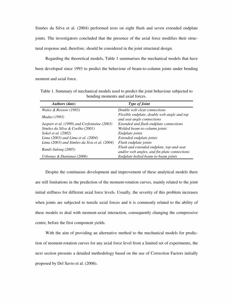
Regarding the theoretical models, Table 1 summarises the mechanical models that have
been developed since 1993 to predict the behaviour of beam-to-column joints under bending
moment and axial force.
Table 1. Summary of mechanical models used to predict the joint behaviour subjected to
bending moments and axial forces.
Authors (date) Type of Joint
Wales & Rossow (1983) Double web cleat connections
Madas (1993) Flexible endplate, double web angle and top
and seat angle connections
Jaspart et al. (1999) and Cerfontaine (2003) Extended and flush endplate connections
Simões da Silva & Coelho (2001) Welded beam-to-column joints
Sokol et al. (2002) Endplate joints
Lima (2003) and Lima et al. (2004) Extended endplate joints
Lima (2003) and Simões da Siva et al. (2004) Flush endplate joints
Ramli-Sulong (2005) Flush and extended endplate, top-and-seat
and/or web angles, and fin-plate connections
Urbonas & Daniunas (2006) Endplate bolted beam-to-beam joints
Despite the continuous development and improvement of these analytical models there
are still limitations in the prediction of the moment-rotation curves, mainly related to the joint
initial stiffness for different axial force levels. Usually, the severity of this problem increases
when joints are subjected to tensile axial forces and it is commonly related to the ability of
these models to deal with moment-axial interaction, consequently changing the compressive
centre, before the first component yields.
With the aim of providing an alternative method to the mechanical models for predic-
tion of moment-rotation curves for any axial force level from a limited set of experiments, the
next section presents a detailed methodology based on the use of Correction Factors initially
proposed by Del Savio et al. (2006).

2 PREDICTION OF MOMENT-ROTATION CURVES FOR ANY AXIAL FORCE LEVEL
FROM A LIMITED SET OF EXPERIMENTS
2.1 General concepts of the Correction Factor
The Correction Factor was initially proposed by Del Savio et al. (2006) to allow for the bend-
ing moment versus axial force interaction, by scaling original moment values present in the
moment versus rotation curves (disregarding the axial force effect). This strategy shifts this
curve up or down depending on the axial force level. However, as it only modifies the bending
moment axis, it is not able to fully describe the bending moment versus rotation associated
with different axial force levels. This fact is highlighted when the joint is subject to a tensile
axial force, where there is a significant difference, mainly, in terms of initial stiffness.
With the aim of improving this basic idea, the Correction Factor has been divided into
two parts: one for the moment axis and another for the rotation axis. Both corrections are in
principle independent, and do not depend on the moment versus axial force interaction dia-
gram, as was the case for the initial idea presented by Del Savio et al. (2006). It is now only a
function of the moment versus rotation curves for different axial force levels.
2.2 Extension of the Correction Factors for both bending moment and rotation axes
As previously noted, there are two corrections, one to the moment axis and another to the rota-
tion axis. As a general approach, the Correction Factor for the moment axis is evaluated in
terms of the bending moment versus rotation curves considering the axial force effect. Using
the design bending moment ratio and considering the axial force effect, the Correction Factor
for the moment axis, CFM, can be evaluated by:
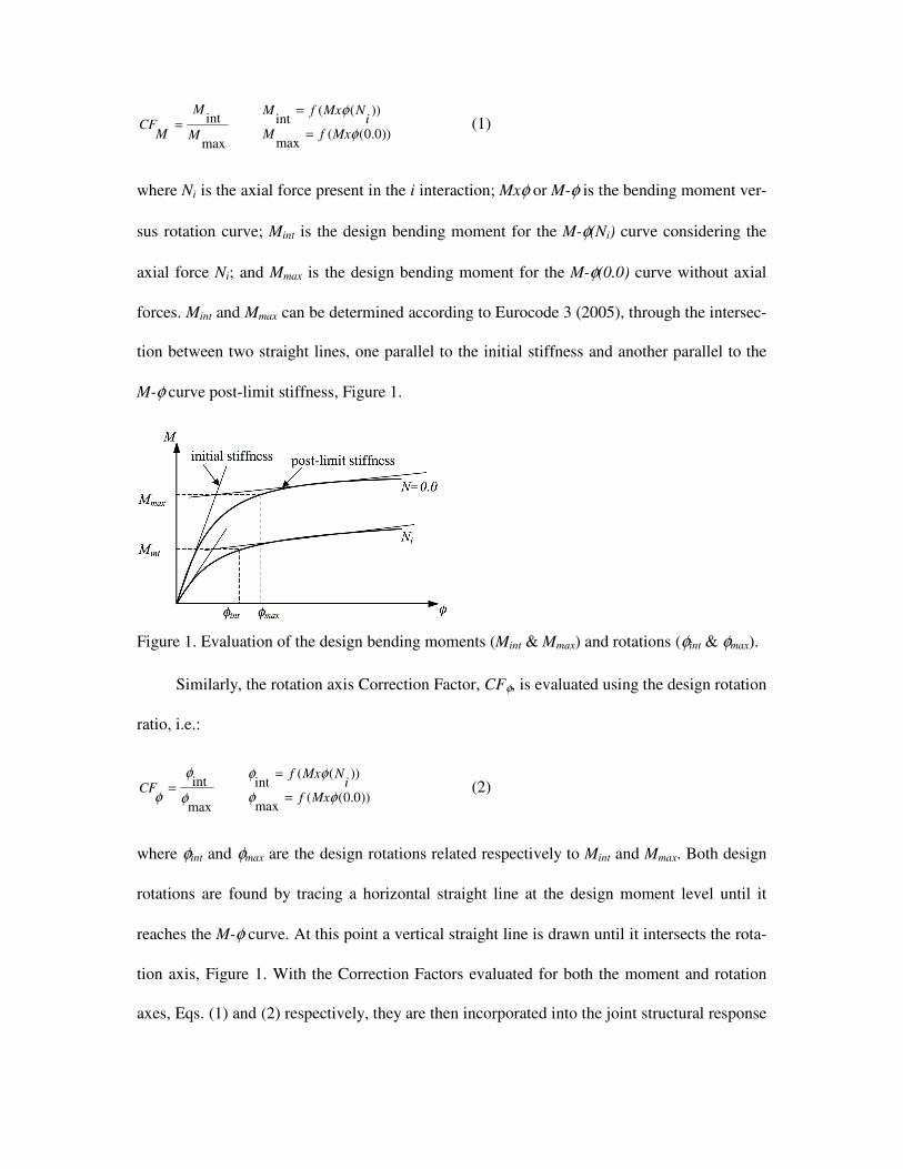
))0.0((max
))((int
max
int
φ
φ
MxfMi
NMxfM
M
M
MCF
=
== (1)
where Ni is the axial force present in the i interaction; Mxφ or M-φ is the bending moment ver-
sus rotation curve; Mint is the design bending moment for the M-φ(Ni) curve considering the
axial force Ni; and Mmax is the design bending moment for the M-φ(0.0) curve without axial
forces. Mint and Mmax can be determined according to Eurocode 3 (2005), through the intersec-
tion between two straight lines, one parallel to the initial stiffness and another parallel to the
M-φ curve post-limit stiffness, Figure 1.
Figure 1. Evaluation of the design bending moments (Mint & Mmax) and rotations (φint & φmax).
Similarly, the rotation axis Correction Factor, CFφ, is evaluated using the design rotation
ratio, i.e.:
))0.0((max
))((int
max
int
φφ
φφ
φ
φ
φ Mxfi
NMxfCF
=
== (2)
where φint and φmax are the design rotations related respectively to Mint and Mmax. Both design
rotations are found by tracing a horizontal straight line at the design moment level until it
reaches the M-φ curve. At this point a vertical straight line is drawn until it intersects the rota-
tion axis, Figure 1. With the Correction Factors evaluated for both the moment and rotation
axes, Eqs. (1) and (2) respectively, they are then incorporated into the joint structural response
considering the moment versus axial force interaction by modifying the M-φ curve for the zero
axial force case, i.e.:
),()(
)()0.0(
00 φφφφ
φφ
CFCFMMxNMx
NMxMx
NMNi
i
××=
→
==
(3)
Basically, the M-φ curve point coordinates MN=0 and φN=0 referred to the moment and the rota-
tion axis coordinates, respectively, for the case without axial forces, are multiplied by the Cor-
rection Factors CFM and CFφ, respectively.
However, only using a pair of Correction Factors throughout the whole M-φ curve, for
the case without axial forces, does not provide a good approximation to the M-φ curve consid-
ering the axial force, because its response is very sensitive to the adopted initial and post-limit
stiffnesses.
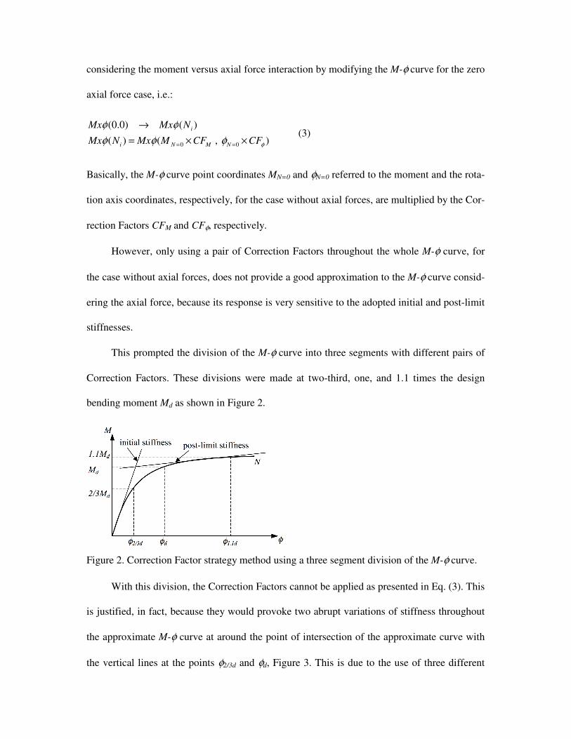
This prompted the division of the M-φ curve into three segments with different pairs of
Correction Factors. These divisions were made at two-third, one, and 1.1 times the design
bending moment Md as shown in Figure 2.
Figure 2. Correction Factor strategy method using a three segment division of the M-φ curve.
With this division, the Correction Factors cannot be applied as presented in Eq. (3). This
is justified, in fact, because they would provoke two abrupt variations of stiffness throughout
the approximate M-φ curve at around the point of intersection of the approximate curve with
the vertical lines at the points φ2/3d and φd, Figure 3. This is due to the use of three different
pairs of Correction Factors evaluated according to Eqs. (1) and (2) at two-third, one, and 1.1
times the design bending moment Md.
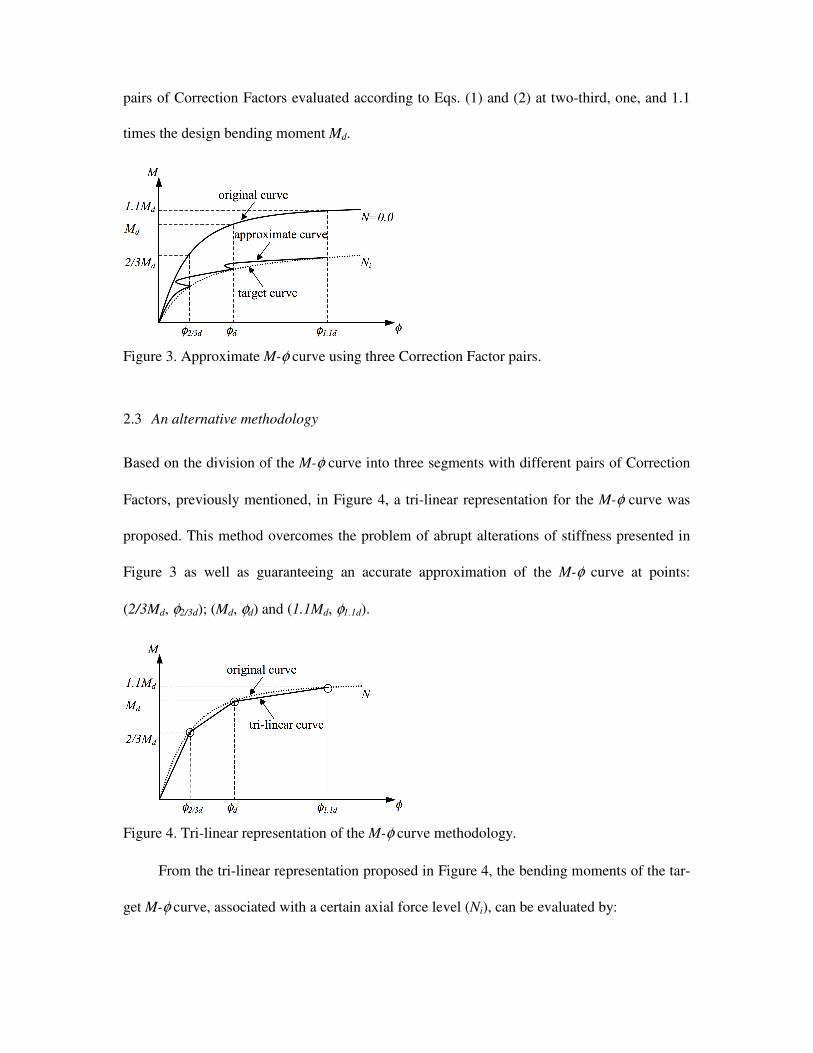
Figure 3. Approximate M-φ curve using three Correction Factor pairs.
2.3 An alternative methodology
Based on the division of the M-φ curve into three segments with different pairs of Correction
Factors, previously mentioned, in Figure 4, a tri-linear representation for the M-φ curve was
proposed. This method overcomes the problem of abrupt alterations of stiffness presented in
Figure 3 as well as guaranteeing an accurate approximation of the M-φ curve at points:
(2/3Md, φ2/3d); (Md, φd) and (1.1Md, φ1.1d).
Figure 4. Tri-linear representation of the M-φ curve methodology.
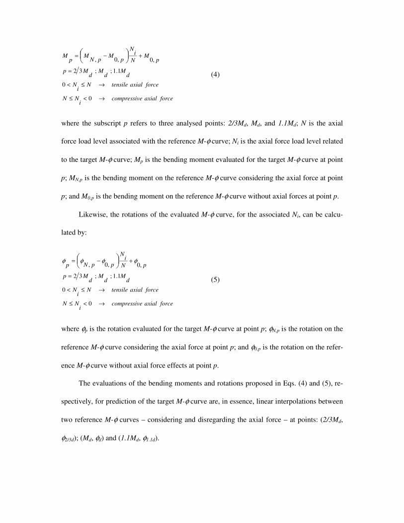
From the tri-linear representation proposed in Figure 4, the bending moments of the tar-
get M-φ curve, associated with a certain axial force level (Ni), can be evaluated by:
forceaxialecompressivi
NN
forceaxialtensileNi
N
dM
dM
dMp
pM
N
iN
pM
pNM
pM
→<≤
→≤<
=
+−=
0
0
1.1;;32
,0,0,
(4)
where the subscript p refers to three analysed points: 2/3Md, Md, and 1.1Md; N is the axial
force load level associated with the reference M-φ curve; Ni is the axial force load level related
to the target M-φ curve; Mp is the bending moment evaluated for the target M-φ curve at point
p; MN,p is the bending moment on the reference M-φ curve considering the axial force at point
p; and M0,p is the bending moment on the reference M-φ curve without axial forces at point p.
Likewise, the rotations of the evaluated M-φ curve, for the associated Ni, can be calcu-
lated by:
forceaxialecompressivi
NN
forceaxialtensileNi
N
dM
dM
dMp
pN
iN
ppNp
→<≤
→≤<
=
+−=
0
0
1.1;;32
,0,0,φφφφ
(5)
where φp is the rotation evaluated for the target M-φ curve at point p; φN,p is the rotation on the
reference M-φ curve considering the axial force at point p; and φ0,p is the rotation on the refer-
ence M-φ curve without axial force effects at point p.
The evaluations of the bending moments and rotations proposed in Eqs. (4) and (5), re-
spectively, for prediction of the target M-φ curve are, in essence, linear interpolations between
two reference M-φ curves – considering and disregarding the axial force – at points: (2/3Md,
φ2/3d); (Md, φd) and (1.1Md, φ1.1d).

3 APPLICATION OF THE PROPOSED METHODOLOGY
The main focus of the methodology presented in section 2.3 is to determine M-φ curves for
any axial force level from two reference M-φ curves. The quality of the obtained approxima-
tions depends on the quality of the M-φ curves used as input to the method. This methodology
requires, at least, two M-φ curves, disregarding and considering either the compressive or ten-
sile axial force effect. However, for a complete behavioural evaluation of the joint three M-φ
curves are necessary: one disregarding the axial force effect; another considering the compres-
sive force effect and finally a third alternative considering the tensile force effect. In this way,
it is possible to study the entirely joint structural response given that loading applied to the
joint may vary from compression to tension.
In order to explain the application of this method to obtain M-φ curves for any axial
force level, as well as to validate its use, experimental tests carried out by Simões da Silva et
al. (2004) and Guisse et al. (1996) on eight flush endplate joints and twelve column bases
have been used.
3.1 Flush endplate joints
This section evaluates experimental tests carried out by Simões da Silva et al. (2004) on eight
flush endplate joints. The geometric properties of the flush endplate, the M-φ curves describ-
ing the experimental behaviour of each test, and the bending moment versus axial force inter-
action diagram are shown in Figures 5 to 7.
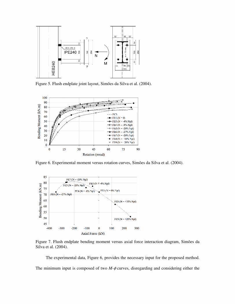
Figure 5. Flush endplate joint layout, Simões da Silva et al. (2004).
Figure 6. Experimental moment versus rotation curves, Simões da Silva et al. (2004).
Figure 7. Flush endplate bending moment versus axial force interaction diagram, Simões da
Silva et al. (2004).
The experimental data, Figure 6, provides the necessary input for the proposed method.
The minimum input is composed of two M-φ curves, disregarding and considering either the
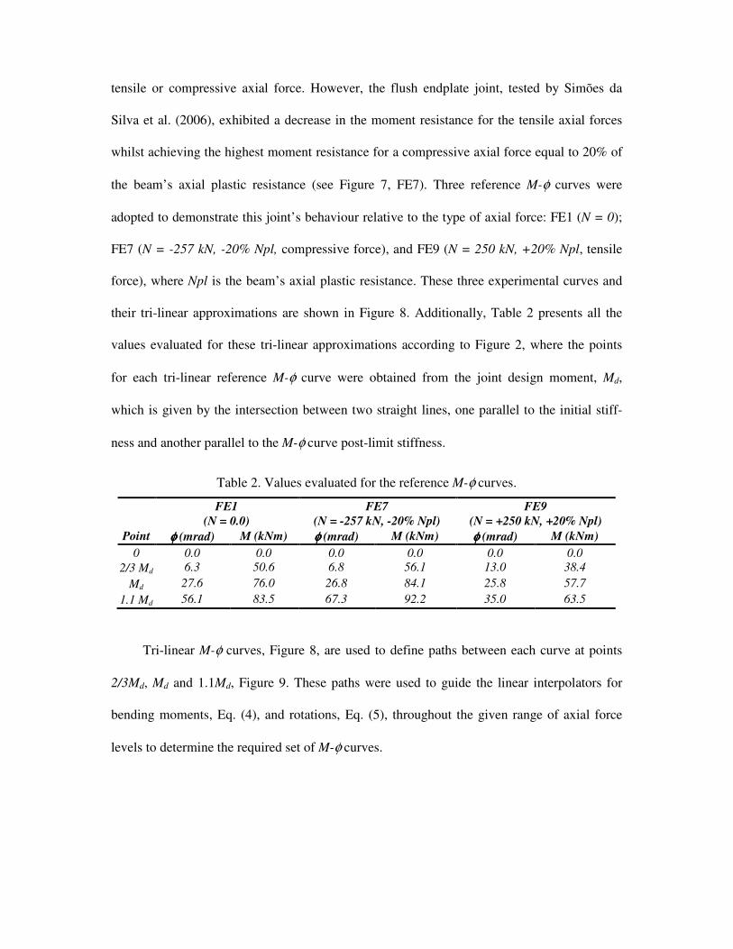
tensile or compressive axial force. However, the flush endplate joint, tested by Simões da
Silva et al. (2006), exhibited a decrease in the moment resistance for the tensile axial forces
whilst achieving the highest moment resistance for a compressive axial force equal to 20% of
the beam’s axial plastic resistance (see Figure 7, FE7). Three reference M-φ curves were
adopted to demonstrate this joint’s behaviour relative to the type of axial force: FE1 (N = 0);
FE7 (N = -257 kN, -20% Npl, compressive force), and FE9 (N = 250 kN, +20% Npl, tensile
force), where Npl is the beam’s axial plastic resistance. These three experimental curves and
their tri-linear approximations are shown in Figure 8. Additionally, Table 2 presents all the
values evaluated for these tri-linear approximations according to Figure 2, where the points
for each tri-linear reference M-φ curve were obtained from the joint design moment, Md,
which is given by the intersection between two straight lines, one parallel to the initial stiff-
ness and another parallel to the M-φ curve post-limit stiffness.
Table 2. Values evaluated for the reference M-φ curves.
FE1
(N = 0.0)
FE7
(N = -257 kN, -20% Npl)
FE9
(N = +250 kN, +20% Npl)
Point φφφφ (mrad) M (kNm) φφφφ (mrad) M (kNm) φφφφ (mrad) M (kNm)
0 0.0 0.0 0.0 0.0 0.0 0.0
2/3 Md 6.3 50.6 6.8 56.1 13.0 38.4
Md 27.6 76.0 26.8 84.1 25.8 57.7
1.1 Md 56.1 83.5 67.3 92.2 35.0 63.5
Tri-linear M-φ curves, Figure 8, are used to define paths between each curve at points
2/3Md, Md and 1.1Md, Figure 9. These paths were used to guide the linear interpolators for
bending moments, Eq. (4), and rotations, Eq. (5), throughout the given range of axial force
levels to determine the required set of M-φ curves.
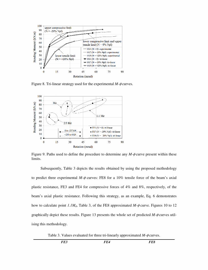
Figure 8. Tri-linear strategy used for the experimental M-φ curves.
Figure 9. Paths used to define the procedure to determine any M-φ curve present within these
limits.
Subsequently, Table 3 depicts the results obtained by using the proposed methodology
to predict three experimental M-φ curves: FE8 for a 10% tensile force of the beam’s axial
plastic resistance, FE3 and FE4 for compressive forces of 4% and 8%, respectively, of the
beam’s axial plastic resistance. Following this strategy, as an example, Eq. 6 demonstrates
how to calculate point 1.1Md, Table 3, of the FE8 approximated M-φ curve. Figures 10 to 12
graphically depict these results. Figure 13 presents the whole set of predicted M-φ curves util-
ising this methodology.
Table 3. Values evaluated for three tri-linearly approximated M-φ curves.
FE3 FE4 FE8
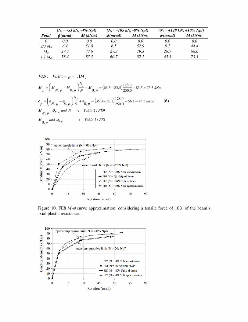
(Ni = -53 kN, -4% Npl) (Ni = -105 kN, -8% Npl) (Ni = +128 kN, +10% Npl)
Point φφφφ (mrad) M (kNm) φφφφ (mrad) M (kNm) φφφφ (mrad) M (kNm)
0 0.0 0.0 0.0 0.0 0.0 0.0
2/3 Md 6.4 51.8 6.5 52.9 9.7 44.4
Md 27.4 77.6 27.3 79.3 26.7 66.6
1.1 Md 58.4 85.3 60.7 87.1 45.3 73.3
( )
( )
1:2,0
9:2;,
3.451.560.250
0.1281.560.35
,0,0,
3.735.830.250
0.1285.835.63
,0,0,
,0
,
1.1int:8
FETableandp
M
FETableNandpN
M
mradpN
iN
ppNp
kNmp
MN
iN
pM
pNM
pM
p
pN
dMpPoFE
→
→
=+−=+−=
=+−=+−=
==
φ
φ
φφφφ (6)
Figure 10. FE8 M-φ curve approximation, considering a tensile force of 10% of the beam’s
axial plastic resistance.
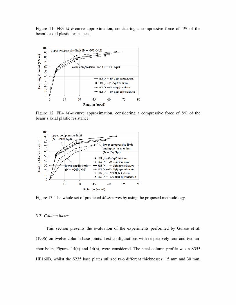
Figure 11. FE3 M-φ curve approximation, considering a compressive force of 4% of the
beam’s axial plastic resistance.
Figure 12. FE4 M-φ curve approximation, considering a compressive force of 8% of the
beam’s axial plastic resistance.
Figure 13. The whole set of predicted M-φ curves by using the proposed methodology.
3.2 Column bases
This section presents the evaluation of the experiments performed by Guisse et al.
(1996) on twelve column base joints. Test configurations with respectively four and two an-
chor bolts, Figures 14(a) and 14(b), were considered. The steel column profile was a S355
HE160B, whilst the S235 base plates utilised two different thicknesses: 15 mm and 30 mm.
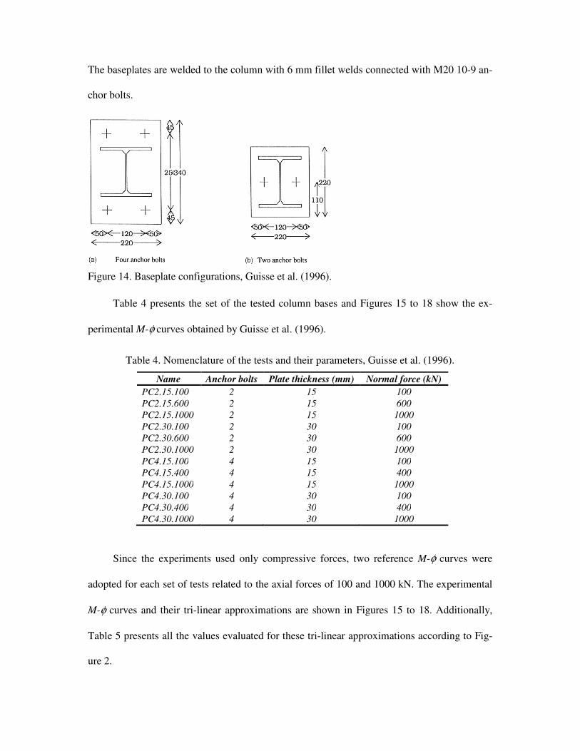
The baseplates are welded to the column with 6 mm fillet welds connected with M20 10-9 an-
chor bolts.
Figure 14. Baseplate configurations, Guisse et al. (1996).
Table 4 presents the set of the tested column bases and Figures 15 to 18 show the ex-
perimental M-φ curves obtained by Guisse et al. (1996).
Table 4. Nomenclature of the tests and their parameters, Guisse et al. (1996).
Name Anchor bolts Plate thickness (mm) Normal force (kN)
PC2.15.100 2 15 100
PC2.15.600 2 15 600
PC2.15.1000 2 15 1000
PC2.30.100 2 30 100
PC2.30.600 2 30 600
PC2.30.1000 2 30 1000
PC4.15.100 4 15 100
PC4.15.400 4 15 400
PC4.15.1000 4 15 1000
PC4.30.100 4 30 100
PC4.30.400 4 30 400
PC4.30.1000 4 30 1000
Since the experiments used only compressive forces, two reference M-φ curves were
adopted for each set of tests related to the axial forces of 100 and 1000 kN. The experimental
M-φ curves and their tri-linear approximations are shown in Figures 15 to 18. Additionally,
Table 5 presents all the values evaluated for these tri-linear approximations according to Fig-
ure 2.
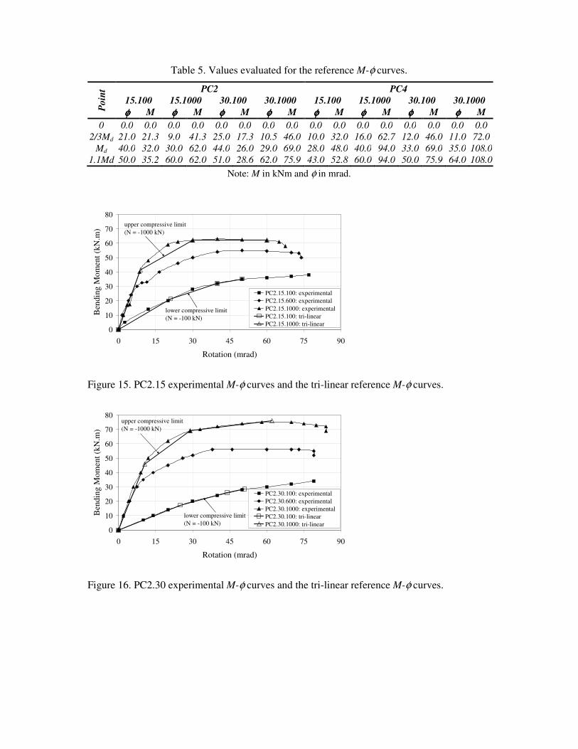
Table 5. Values evaluated for the reference M-φ curves.
Poin
t PC2 PC4
15.100 15.1000 30.100 30.1000 15.100 15.1000 30.100 30.1000
φφφφ M φφφφ M φφφφ M φφφφ M φφφφ M φφφφ M φφφφ M φφφφ M
0 0.0 0.0 0.0 0.0 0.0 0.0 0.0 0.0 0.0 0.0 0.0 0.0 0.0 0.0 0.0 0.0
2/3Md 21.0 21.3 9.0 41.3 25.0 17.3 10.5 46.0 10.0 32.0 16.0 62.7 12.0 46.0 11.0 72.0
Md 40.0 32.0 30.0 62.0 44.0 26.0 29.0 69.0 28.0 48.0 40.0 94.0 33.0 69.0 35.0 108.0
1.1Md 50.0 35.2 60.0 62.0 51.0 28.6 62.0 75.9 43.0 52.8 60.0 94.0 50.0 75.9 64.0 108.0
Note: M in kNm and φ in mrad.
0
10
20
30
40
50
60
70
80
0 15 30 45 60 75 90
Rotation (mrad)
Ben
din
g M
om
ent
(kN
.m)
PC2.15.100: experimental
PC2.15.600: experimental
PC2.15.1000: experimental
PC2.15.100: tri-linear
PC2.15.1000: tri-linear
upper compressive limit
(N = -1000 kN)
lower compressive limit
(N = -100 kN)
Figure 15. PC2.15 experimental M-φ curves and the tri-linear reference M-φ curves.
0
10
20
30
40
50
60
70
80
0 15 30 45 60 75 90
Rotation (mrad)
Ben
din
g M
om
ent
(kN
.m)
PC2.30.100: experimental
PC2.30.600: experimental
PC2.30.1000: experimental
PC2.30.100: tri-linear
PC2.30.1000: tri-linear
upper compressive limit
(N = -1000 kN)
lower compressive limit
(N = -100 kN)
Figure 16. PC2.30 experimental M-φ curves and the tri-linear reference M-φ curves.
0
20
40
60
80
100
120
0 15 30 45 60 75 90
Rotation (mrad)
Ben
din
g M
om
ent
(kN
.m)
PC4.15.100: experimental
PC4.15.400: experimental
PC4.15.1000: experimental
PC4.15.100: tri-linear
PC4.15.1000: tri-linear
upper compressive limit
(N = -1000 kN)
lower compressive limit
(N = -100 kN)
Figure 17. PC4.15 experimental M-φ curves and the tri-linear reference M-φ curves.
0
20
40
60
80
100
120
0 15 30 45 60 75 90
Rotation (mrad)
Ben
din
g M
om
ent
(kN
.m)
PC4.30.100: experimental
PC4.30.400: experimental
PC4.30.1000: experimental
PC4.30.100: tri-linear
PC4.30.1000: tri-linear
upper compressive limit
(N = -1000 kN)
lower compressive limit
(N = -100 kN)
Figure 18. PC4.30 experimental M-φ curves and the tri-linear reference M-φ curves.
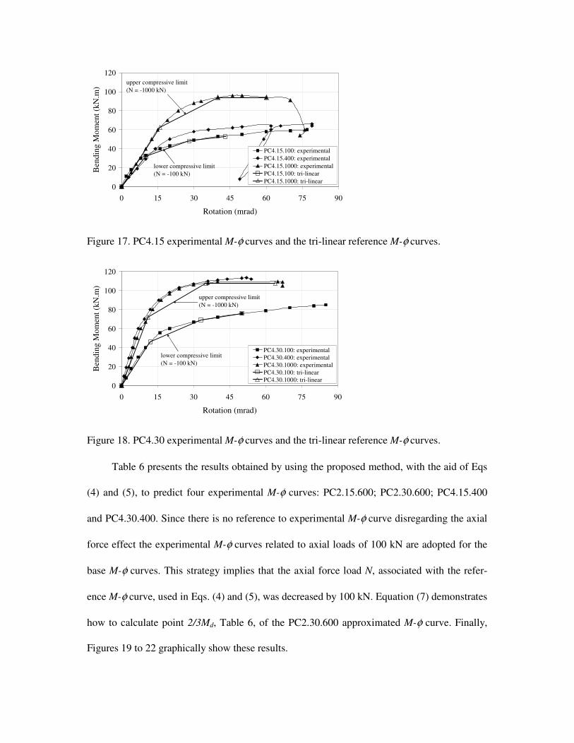
Table 6 presents the results obtained by using the proposed method, with the aid of Eqs
(4) and (5), to predict four experimental M-φ curves: PC2.15.600; PC2.30.600; PC4.15.400
and PC4.30.400. Since there is no reference to experimental M-φ curve disregarding the axial
force effect the experimental M-φ curves related to axial loads of 100 kN are adopted for the
base M-φ curves. This strategy implies that the axial force load N, associated with the refer-
ence M-φ curve, used in Eqs. (4) and (5), was decreased by 100 kN. Equation (7) demonstrates
how to calculate point 2/3Md, Table 6, of the PC2.30.600 approximated M-φ curve. Finally,
Figures 19 to 22 graphically show these results.
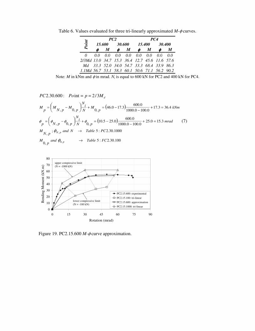
Table 6. Values evaluated for three tri-linearly approximated M-φ curves.
Poin
t PC2 PC4
15.600 30.600 15.400 30.400
φφφφ M φφφφ M φφφφ M φφφφ M
0 0.0 0.0 0.0 0.0 0.0 0.0 0.0 0.0
2/3Md 13.0 34.7 15.3 36.4 12.7 45.6 11.6 57.6
Md 33.3 52.0 34.0 54.7 33.3 68.4 33.9 86.3
1.1Md 56.7 53.1 58.3 60.1 50.6 71.1 56.2 90.2
Note: M in kNm and φ in mrad. Ni is equal to 600 kN for PC2 and 400 kN for PC4.
( )
( )
100.30.2:5,0
1000.30.2:5;,
3.150.250.1000.1000
0.6000.255.10
,0,0,
4.363.170.1000.1000
0.6003.170.46
,0,0,
,0
,
3/2int:600.30.2
FCTableandp
M
PCTableNandpN
M
mradpN
iN
ppNp
kNmp
MN
iN
pM
pNM
pM
p
pN
dMpPoPC
→
→
=+−
−=+−=
=+−
−=+−=
==
φ
φ
φφφφ (7)
0
10
20
30
40
50
60
70
80
0 15 30 45 60 75 90
Rotation (mrad)
Ben
din
g M
om
ent
(kN
.m)
PC2.15.600: experimental
PC2.15.100: tri-linear
PC2.15.600: approximation
PC2.15.1000: tri-linear
upper compressive limit
(N = -1000 kN)
lower compressive limit
(N = -100 kN)
Figure 19. PC2.15.600 M-φ curve approximation.
0
10
20
30
40
50
60
70
80
0 15 30 45 60 75 90
Rotation (mrad)
Ben
din
g M
om
ent
(kN
.m)
PC2.30.600: experimental
PC2.30.100: tri-linear
PC2.30.600: approximation
PC2.30.1000: tri-linear
upper compressive limit
(N = -1000 kN)
lower compressive limit
(N = -100 kN)
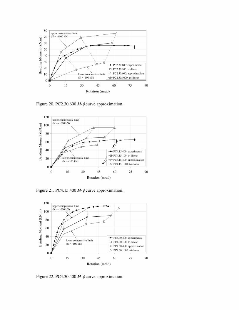
Figure 20. PC2.30.600 M-φ curve approximation.
0
20
40
60
80
100
120
0 15 30 45 60 75 90
Rotation (mrad)
Ben
din
g M
om
ent
(kN
.m)
PC4.15.400: experimental
PC4.15.100: tri-linear
PC4.15.400: approximation
PC4.15.1000: tri-linear
upper compressive limit
(N = -1000 kN)
lower compressive limit
(N = -100 kN)
Figure 21. PC4.15.400 M-φ curve approximation.
0
20
40
60
80
100
120
0 15 30 45 60 75 90
Rotation (mrad)
Ben
din
g M
om
ent
(kN
.m)
PC4.30.400: experimental
PC4.30.100: tri-linear
PC4.30.400: approximation
PC4.30.1000: tri-linear
upper compressive limit
(N = -1000 kN)
lower compressive limit
(N = -100 kN)
Figure 22. PC4.30.400 M-φ curve approximation.
4 RESULTS AND DISCUSSION
Three flush endplate joint experimental M-φ curves, Simões da Silva et al. (2004), were
evaluated and are depicted in Figures 10-13. They were used to validate the proposed method-
ology presented in section 2.3 as well as to demonstrate its application.
Figure 10 illustrates an approximation for the FE8 M-φ curve that considers a tensile
force equal to 10% of the beam’s axial plastic resistance. This approximation was obtained
from two tri-linear M-φ curves, disregarding and considering a tensile force of 20% of the
beam’s axial plastic resistance. This approximation was very close to the FE8 M-φ test curve,
Table 7.
Figures 11 and 12, present approximations for FE3 and FE4 M-φ curves that respec-
tively consider compressive forces of 4% and 8% of the beam’s axial plastic resistance. These
approximations were obtained from two tri-linear M-φ curves, disregarding and considering a
compressive force of 20% of the beam’s axial plastic resistance. The approximation for FE4
M-φ curve, Figure 12, was relatively close to the experimental curve, Table 7. However, for
FE3 M-φ curve, Figure 11, the obtained response was not as good, underestimating the joint
flexural capacity by 11%, Table 7. This was due to the behaviour of this experimental curve
when compared to the others. It is possible to observe in Figure 7 that there is an increase in
the flush endplate joint moment capacity from FE1 M-φ curve (N = 0% Npl) to FE7 M-φ curve
(N = -20% Npl). However, within this range, with a 4% beam’s compressive plastic resistance
the flexural capacity is larger than the maximum moment obtained with the 8% test. Follow-
ing this increasing tendency in the joint flexural capacity registered from FE1 (N = 0% Npl) to
FE7 (N = -20% Npl), the maximum moment obtained with FE4 (N = -8% Npl) should be lar-
ger than FE3 (N = -4% Npl). A possible reason for this perturbation in the experimental re-
sults might be related to problems with the FE3 experimental test such as measuring errors or
assembly eccentricities.
In general, the predictions of the M-φ curves using the methodology proposed in section
2.3 provided accurate correlations with the test curves from Simões da Silva et al. (2004) as
can be seen in Table 7.
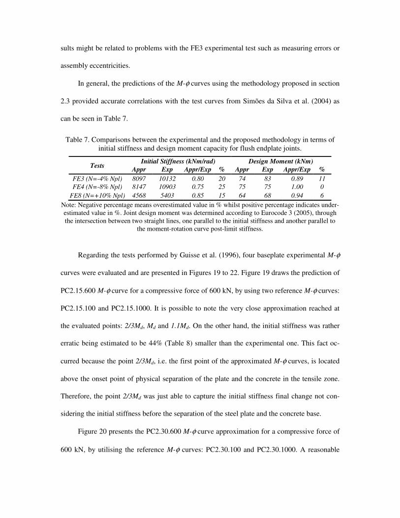
Table 7. Comparisons between the experimental and the proposed methodology in terms of
initial stiffness and design moment capacity for flush endplate joints.
Tests Initial Stiffness (kNm/rad) Design Moment (kNm)
Appr Exp Appr/Exp % Appr Exp Appr/Exp %
FE3 (N=-4% Npl) 8097 10132 0.80 20 74 83 0.89 11
FE4 (N=-8% Npl) 8147 10903 0.75 25 75 75 1.00 0
FE8 (N=+10% Npl) 4568 5403 0.85 15 64 68 0.94 6
Note: Negative percentage means overestimated value in % whilst positive percentage indicates under-
estimated value in %. Joint design moment was determined according to Eurocode 3 (2005), through
the intersection between two straight lines, one parallel to the initial stiffness and another parallel to
the moment-rotation curve post-limit stiffness.
Regarding the tests performed by Guisse et al. (1996), four baseplate experimental M-φ
curves were evaluated and are presented in Figures 19 to 22. Figure 19 draws the prediction of
PC2.15.600 M-φ curve for a compressive force of 600 kN, by using two reference M-φ curves:
PC2.15.100 and PC2.15.1000. It is possible to note the very close approximation reached at
the evaluated points: 2/3Md, Md and 1.1Md. On the other hand, the initial stiffness was rather
erratic being estimated to be 44% (Table 8) smaller than the experimental one. This fact oc-
curred because the point 2/3Md, i.e. the first point of the approximated M-φ curves, is located
above the onset point of physical separation of the plate and the concrete in the tensile zone.
Therefore, the point 2/3Md was just able to capture the initial stiffness final change not con-
sidering the initial stiffness before the separation of the steel plate and the concrete base.
Figure 20 presents the PC2.30.600 M-φ curve approximation for a compressive force of
600 kN, by utilising the reference M-φ curves: PC2.30.100 and PC2.30.1000. A reasonable
approximation was obtained for this M-φ curve, however the initial stiffness was underesti-
mated by 32% and the flexural capacity was slightly under predicted by 5%, Table 8.
Figure 21 demonstrates the PC4.15.400 M-φ curve prediction for a compressive force of
400 kN, by employing the base M-φ curves: PC4.15.100 and PC4.15.1000. A good correlation
between the experimental tests and numerical results was obtained. Unlike the others results,
the initial stiffness and the design bending moment were over predicted by 26% and 3%, re-
spectively.
Finally, Figure 22 presents the estimation of the PC4.30.400 M-φ curve for a compres-
sive force of 400 kN, by having as basis PC4.30.100 and PC4.30.1000 M-φ curves. This case
did not produce an accurate prediction of the M-φ curve, Table 8. However, this fact may be
justified due to the occurrence of the column end section yielding as well as column flange lo-
cal plate buckling. In others words, the column capacity was reached before achieving the
base plate joint flexural capacity.
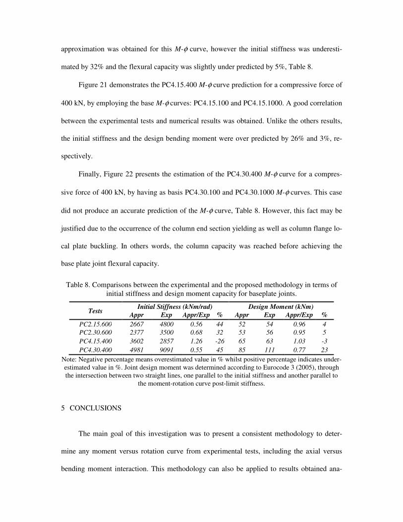
Table 8. Comparisons between the experimental and the proposed methodology in terms of
initial stiffness and design moment capacity for baseplate joints.
Tests Initial Stiffness (kNm/rad) Design Moment (kNm)
Appr Exp Appr/Exp % Appr Exp Appr/Exp %
PC2.15.600 2667 4800 0.56 44 52 54 0.96 4
PC2.30.600 2377 3500 0.68 32 53 56 0.95 5
PC4.15.400 3602 2857 1.26 -26 65 63 1.03 -3
PC4.30.400 4981 9091 0.55 45 85 111 0.77 23
Note: Negative percentage means overestimated value in % whilst positive percentage indicates under-
estimated value in %. Joint design moment was determined according to Eurocode 3 (2005), through
the intersection between two straight lines, one parallel to the initial stiffness and another parallel to
the moment-rotation curve post-limit stiffness.
5 CONCLUSIONS
The main goal of this investigation was to present a consistent methodology to deter-
mine any moment versus rotation curve from experimental tests, including the axial versus
bending moment interaction. This methodology can also be applied to results obtained ana-
lytically, empirically, mechanically, and numerically. Due to its simplicity and to the fact that
its basis is M-φ curves that already consider the moment versus axial force interaction, it can
be easily incorporated into a nonlinear semi-rigid joint finite element formulation. It is also
important to observe that the use of the proposed methodology does not change the basic for-
mulation of the non-linear joint finite element, only requiring a rotational stiffness update pro-
cedure.
This proposed method is a simple and accurate way of introducing semi-rigid joint ex-
perimental test data into structural analysis, through M-φ curves. Application and validation of
the proposed methodology to obtain M-φ curves, for different axial force levels, were per-
formed against experimental tests executed by Simões da Silva et al. (2004) and Guisse et al.
(1996) on eight flush endplate and on twelve column base joints, respectively.
Finally, it may be suggested that an alternative, though accurate, method to determine
M-φ curves for endplate and baseplate joints, considering the bending moment versus axial
force interactions, can be made with a simple linear interpolation between two reference M-φ
curves providing a straightforward procedure to obtain M-φ curves for any axial force level.
6 ACKNOWLEGEMENTS
The authors gratefully acknowledge the financial support provided by the Brazilian National
and State Scientific and Technological Developing Agencies: CNPq, CAPES and FAPERJ.
This arrangement financed the first author’s period as a visiting scholar at Imperial College
London.
7 REFERENCES
Cerfontaine, F., “Etude de l’interaction entre moment de flexion et effort normal dans les assemblages boulon-nés”. Doctor en Sciences appliquées – Université de Liege, Faculté des Sciences Appliquées, 2003. (in French).
Del Savio, A.A., Andrade, S.A. de, Vellasco, P.C.G.S., Martha, L.F. & Lima, L.R.O. de., “Semi-Rigid Portal Frame Finite Element Modelling Including the Axial Versus Bending Moment Interaction in the Structural Joints”, Proceedings of International Colloquia on Stability and Ductility of Steel Structures - SDSS'06, Lis-boa, 2006, vol. 1, pp.1-8.
European Committee for Standardisation, Eurocode 3: Design of steel structures – Part 1.8: design of joints. Brus-sels, May 2005.
Guisse, S., Vandegans, D. & Jaspart, J.-P., “Application of the component method to column bases – experimen-tation and development of a mechanical model for characterization”, Report no. MT 195, Liege: Research Centre of the Belgian Metalworking Industry, 1996.
Jaspart J.-P., Braham, M. & Cerfontaine, F., “Strength of joints subjected to combined action of bending moments and axial forces”, Proceedings of the First European Conference on Steel Structures, Eurosteel, 1999, pp.465-468.
Li, T.Q., Choo, B.S. & Nethercot, D.A., “Connection element method for the analysis of semi-rigid frames”, Journal Constructional Steel Research, 1995, 32, pp.143-171.
Lima, L.R.O. de., “Behaviour of endplate beam-to-column joints under bending and axial force”. Ph.D. Thesis. PUC-Rio, Pontifical Catholic University, Civil Eng. Dept., Rio de Janeiro, Brazil, 2003. (in Portuguese)
Lima, L.R.O. de, Simoes da Silva, L., Vellasco, P.C.G.S. & Andrade, S.A. de., “Experimental evaluation of ex-tended end-plate beam-to-column joints subjected to bending and axial force”, Engineering Structures, 2004, 26, pp.1333-1347.
Madas, J.P., “Advanced modelling of composite frames subjected to earthquake loading”. PhD Thesis, Imperial College Science, Technology and Medicine, University of London, 1993.
Nethercot, D.A. & Zandonini, R., “Methods of prediction of joint behaviour: beam-to-column connections”, Structural Connections: Stability and Strength, Elsevier Applied Science, London and New York, Chapter 2, pp.23-62, 1989.
Ramli-Sulong, N.H., “Behaviour of steel connections under fire conditions”. PhD Thesis, Imperial College Lon-don, University of London, 2005.
Simões da Silva, L. & Coelho, A.M.G., “An analytical evaluation of the response of steel joints under bending and axial force”, Computers & Structures, 2001, 79, pp.873-881.
Simões da Silva, L., Lima, L.R.O. de, Vellasco, P.C.G.S. & Andrade, S.A. de., “Behaviour of flush end-plate beam-to-column joints under bending and axial force”, Steel and Composite Structures, 2004, 4(2), pp.77-94.
Sokol, Z., Wald, F., Delabre, V., Muzeau, J.-P. & Svarc, M., “Design of endplate joints subject to moment and normal force”, Proceedings of Third European Conference on Steel Structures – Eurosteel 2002, Coimbra, Cmm Press, 2002, pp.1219-1228.
Urbonas, K. & Daniunas, A., “Behaviour of semi-rigid steel beam-to-beam joints under bending and axial forces”, Journal of Constructional Steel Research, 2006, 62, pp.1244-1249.
Vlassis, A.G., Izzuddin, B.A., Elghazouli, A.Y. & Nethercot, D.A., “Design oriented approach for progressive collapse assessment of steel framed buildings”, Structural Engineering International (Report), SEI Editorial Board, 2006, pp.129-136.
Wald, F. & Svarc, M., “Experimental with endplate joints subject to moment and normal force. Contribution to experimental investigation of engineering materials and structures”, CTU Report n: 2-3, Prague, 2001, pp.1-13.
Wales, M.W. & Rossow, E.C., “Coupled moment-axial force behaviour in bolted joints”, Journal of Structural Engineering, ASCE, 1983, 109(5), pp.1250-1266.