Embed Size (px)
Citation preview
1
BUCKLING OF BEAMS WITH
INFLECTION POINTS
Joseph A. Yura1 and Todd A. Helwig
2
ABSTRACT
The buckling behavior of beams with reverse curvature bending can be
complex since both flanges are subjected to compression at different
locations along the unbraced length. Design engineers frequently raise
questions regarding the inflection point behaving as a braced point in
continuous construction. The problem is further complicated when the
top flange is braced by closely-spaced joists or composite construction
while the bottom flange is unbraced. Although the moment is zero at the
inflection point, the location can not generally be treated as a braced
point because the section can still twist at this location. A variety of
commonly encountered design problems are discussed and simple
solutions are provided in the form of Cb factors applied to the uniform
moment solution. The problems that are considered include beams with
reverse curvature bending with no intermediate bracing, as well as
members with continuous bracing on the top flange. For members with
bracing on one flange, solutions are presented for lateral bracing,
torsional bracing and composite construction.
1 Professor Emeritus, Department of Civil, Arch. and Env. Engineering, The
University of Texas at Austin, Austin, TX 78712 2 Associate Professor, Department of Civil, Arch. and Env. Engineering, The
University of Texas at Austin, Austin, TX 78712
2
INTRODUCTION
Two of the primary factors that affect the lateral-torsional buckling
capacity of a beam are the unbraced length and the distribution of
bending moment along the member. Effects of moment gradient are
usually accounted for by adjusting the buckling solution derived for
uniform moment loading. However, when addressing the unbraced
length, engineers are often unsure what constitutes a braced point. This
is particularly true for beams with inflection points due to reverse
curvature bending. Since the moment is zero at the inflection point,
questions frequently arise regarding this point behaving as a braced
point (AISC-1993, 1995, CISC, 2003). In many of these situations the
top flange of the girder may be laterally braced by a flooring system or
joists, while the bottom flange is unbraced.
As the name implies, the lateral-torsional buckling mode of beams
involves both lateral translation and twist of the cross section. Bracing
that restrains one point on the cross section from lateral movement does
not ensure adequate bracing. However, preventing twist of the cross
section ensures that the point is braced (Yura, 1993). This paper
focuses on the buckling behavior of beams with inflection points.
Background information is presented in the next section followed by
finite element results on beams with reverse curvature bending. Several
bracing scenarios with reverse curvature bending are considered,
ranging from cases with no intermediate bracing to situations with
lateral bracing on one flange only. Expressions for Cb factors that
reflect the beneficial effects of the bracing are presented and discussed.
BACKGROUND
Most design specifications employ lateral-torsional buckling solutions
that were developed for constant bending moment and account for
variable moment with Cb factors applied to the uniform moment
3
solution. For doubly-symmetric sections with uniform moment loading
(Cb = 1.0), the elastic buckling moment (Timoshenko and Gere, 1961)
is
cr b y y w
b b
EM C EI GJ I C
L L
2
(1)
where Lb = unbraced length, E = modulus of elasticity, G = shear
modulus, J = torsional constant, Iy = weak axis moment of inertia and
Cw = warping constant. The first term under the radical in Eq.1 relates
to the St. Venant torsional stiffness, while the second term within the
radical reflects the warping stiffness of the beam. In the derivation of
Eq.1, only the boundary conditions that twist was prevented at the ends
of the unbraced length and no warping restraint at the ends were used.
No lateral displacement boundary condition was necessary. Thus,
locations along the length of the member where twist is prevented are
defined as brace points, For beams with moment gradient, Kirby and
Nethercot (1979) presented a general expression for Cb that is
applicable to a variety of moment diagram shapes within the unbraced
length. Their equation was adjusted slightly and is presented in the
American Institute of Steel Construction Specification (AISC, 2005) in
the following form:
12 5
2 5 3 4 3
maxb
max A B C
. MC
. M M M M
(2)
where, within the unbraced beam segment, Mmax = maximum moment,
MA , MC = moments at the quarter points and MB =moment at the center.
The absolute values of all moments are used with Eq. 2.
The unbraced length to be used with Eq.1 for beams with inflection
points can be misinterpreted, especially if the definition of Lb in design
specifications refers to the unbraced length of the compression flange.
Since the inflection point defines the switch from compression to
tension in the flange, can the inflection point be used to define Lb? The
inflection point generally does not act as a braced point since the
4
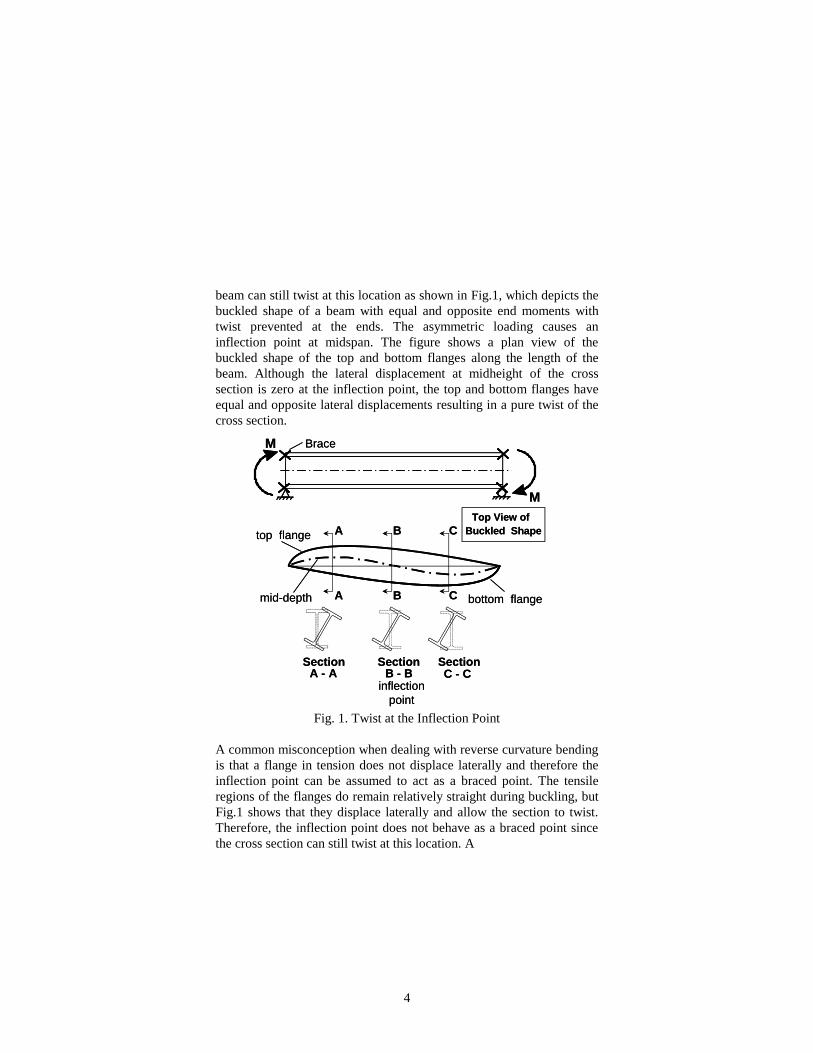
beam can still twist at this location as shown in Fig.1, which depicts the
buckled shape of a beam with equal and opposite end moments with
twist prevented at the ends. The asymmetric loading causes an
inflection point at midspan. The figure shows a plan view of the
buckled shape of the top and bottom flanges along the length of the
beam. Although the lateral displacement at midheight of the cross
section is zero at the inflection point, the top and bottom flanges have
equal and opposite lateral displacements resulting in a pure twist of the
cross section.
Fig. 1. Twist at the Inflection Point
A common misconception when dealing with reverse curvature bending
is that a flange in tension does not displace laterally and therefore the
inflection point can be assumed to act as a braced point. The tensile
regions of the flanges do remain relatively straight during buckling, but
Fig.1 shows that they displace laterally and allow the section to twist.
Therefore, the inflection point does not behave as a braced point since
the cross section can still twist at this location. A
M
M
Brace
mid-depth
top flange
bottom flange
Buckled Shape
Top View of
A
A
B
B
C
C
SectionA - A
Section SectionC - CB - B
inflection
point
M
M
Brace
mid-depth
top flange
bottom flange
Buckled Shape
Top View of
A
A
B
B
C
C
SectionA - A
Section SectionC - CB - B
inflection
point
5
single lateral brace attached to just one of the flanges at the inflection
point also does not prevent twist and only increases Mcr approximately
10% (Yura, 1993). Bracing both flanges at the inflection point more
than doubles the value of Mcr.
A design approach that is consistent with current design provisions is to
define the unbraced length as the spacing between points of zero twist,
and to account for effects of the inflection points with Cb factors
applied to a uniform moment buckling solution. The remainder of this
paper will therefore focus on Cb expressions for frequently encountered
details that affect a beams buckling capacity. Finite element solutions
(FEA) are presented in the paper for a variety of loading conditions.
The cross section that was used in the majority of the analyses was a
W16x26 section with a span-to depth ratio, L/d, of 15 and 30.
UNBRACED BEAMS
Lateral-torsional buckling strength can be determined by using the Cb
expression give by Eq. 2 provided that the unbraced length is defined
between points of zero twist. The buckling moment is compared to the
maximum applied moment within the unbraced length under
consideration. Eq. 2 is valid for both single- and reverse-curvature
bending of doubly-symmetric sections and is applicable for any shape
moment diagram between points of zero twist.
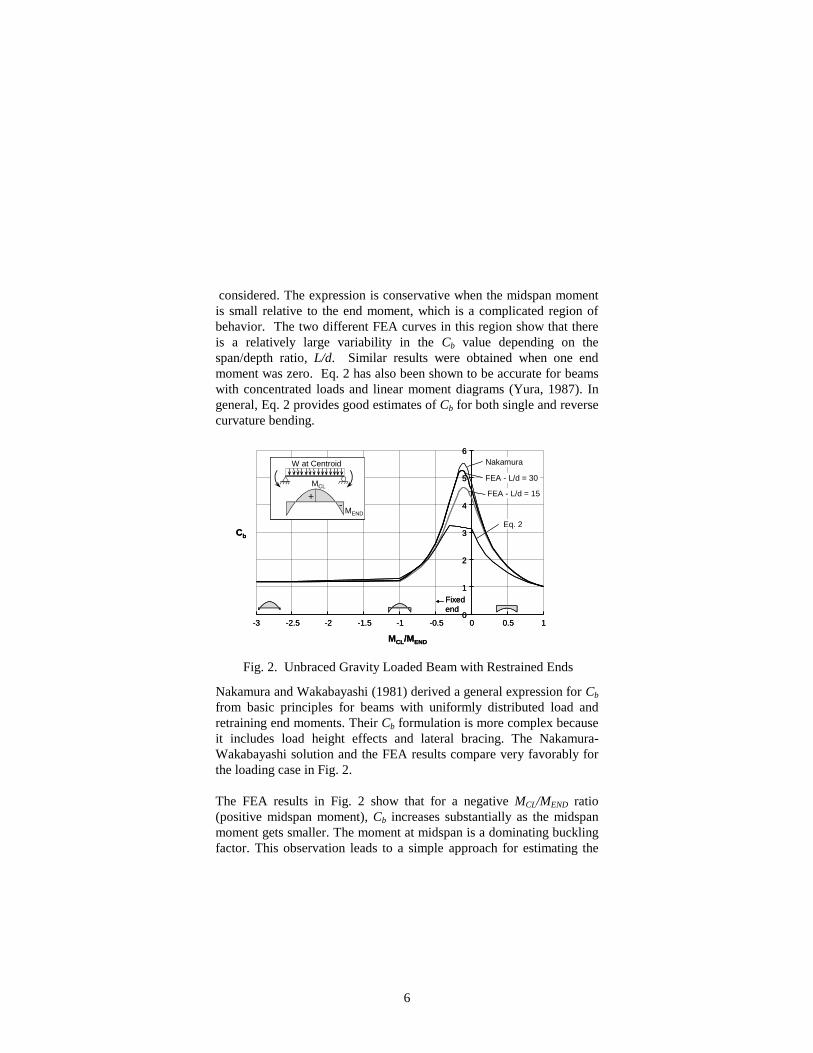
The accuracy of Eq. 2 with FEA solutions are presented in Fig. 2 for a
W16x26 beam with a distributed load applied at the centroid. The beam
was subjected to similar concentrated in-plane moments at the two ends
to simulate continuity. Although no intermediate bracing was provided
along the length of the beam, twist was prevented at the ends of the
beam. Since the beams were free to warp at the supports, the results will
be conservative for continuous construction. The Cb is graphed on the
vertical axis versus the ratio of the midspan moment, MCL, to the end
moment, MEND. Eq. 2 has good agreement with the FEA results over
the wide range of moment distributions that were
6
considered. The expression is conservative when the midspan moment
is small relative to the end moment, which is a complicated region of
behavior. The two different FEA curves in this region show that there
is a relatively large variability in the Cb value depending on the
span/depth ratio, L/d. Similar results were obtained when one end
moment was zero. Eq. 2 has also been shown to be accurate for beams
with concentrated loads and linear moment diagrams (Yura, 1987). In
general, Eq. 2 provides good estimates of Cb for both single and reverse
curvature bending.
Nakamura and Wakabayashi (1981) derived a general expression for Cb
from basic principles for beams with uniformly distributed load and
retraining end moments. Their Cb formulation is more complex because
it includes load height effects and lateral bracing. The Nakamura-
Wakabayashi solution and the FEA results compare very favorably for
the loading case in Fig. 2.
The FEA results in Fig. 2 show that for a negative MCL/MEND ratio
(positive midspan moment), Cb increases substantially as the midspan
moment gets smaller. The moment at midspan is a dominating buckling
factor. This observation leads to a simple approach for estimating the
Fig. 2. Unbraced Gravity Loaded Beam with Restrained Ends
0
1
2
3
4
5
6
-3 -2.5 -2 -1.5 -1 -0.5 0 0.5 1
FEA - L/d = 30
FEA - L/d = 15
Fixed
end
Eq. 2
Nakamura
MCL/MEND
Cb
MEND
MCL
+-
W at Centroid
0
1
2
3
4
5
6
-3 -2.5 -2 -1.5 -1 -0.5 0 0.5 1
FEA - L/d = 30
FEA - L/d = 15
Fixed
end
Eq. 2
Nakamura
MCL/MEND
Cb
MEND
MCL
+-
W at Centroid
MEND
MCL
+-
W at Centroid
7
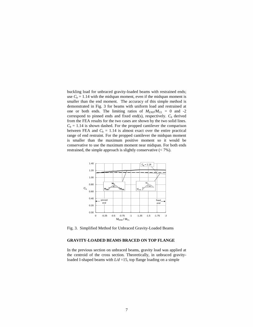
buckling load for unbraced gravity-loaded beams with restrained ends;
use Cb = 1.14 with the midspan moment, even if the midspan moment is
smaller than the end moment. The accuracy of this simple method is
demonstrated in Fig. 3 for beams with uniform load and restrained at
one or both ends. The limiting ratios of MEND/MCL = 0 and -2
correspond to pinned ends and fixed end(s), respectively. Cb derived
from the FEA results for the two cases are shown by the two solid lines.
Cb = 1.14 is shown dashed. For the propped cantilever the comparison
between FEA and Cb = 1.14 is almost exact over the entire practical
range of end restraint. For the propped cantilever the midspan moment
is smaller than the maximum positive moment so it would be
conservative to use the maximum moment near midspan. For both ends
restrained, the simple approach is slightly conservative (< 7%).
Fig. 3. Simplified Method for Unbraced Gravity-Loaded Beams
GRAVITY-LOADED BEAMS BRACED ON TOP FLANGE
In the previous section on unbraced beams, gravity load was applied at
the centroid of the cross section. Theoretically, in unbraced gravity-
loaded I-shaped beams with L/d =15, top flange loading on a simple
0.00
0.20
0.40
0.60
0.80
1.00
1.20
1.40
-2-1.75-1.5-1.25-1-0.75-0.5-0.250
Cb
MEND / MCL
MEND
MCL
+ -MEND- MEND
MCL
+ -MEND- MEND
MCL
+ -MEND-
pinnedend
fixedend
Cb = 1.14
MEND
MCL
-+
MEND
MCL
-+
8
span reduces the buckling load 30% (Nethercot and Rocky, 1972).
When there are inflection points between the brace points, the load
height effect is greater: 45% for a propped cantilever (one inflection
point) and 60% for a fixed-end beam (two inflection points). For longer
beams, the load height effect is less significant than for shorter spans.
Top flange loading was not considered previously because the loading
system typically also provides bracing at the location where the load is
applied. In this section, however, the top flange is braced continuously
so gravity loading will also be applied at the top flange. The Cb factors
generated are applied to Eq. 1 unless otherwise noted. The Cb factor
accounts for the effects of moment gradient, top flange loading and top
flange bracing. Lb will be the unbraced length of the bottom flange.
There are three general types of bracing that improve the buckling
strength of I-shaped beams: lateral bracing, torsional bracing and
diaphragm bracing. Lateral bracing prevents lateral movement at the
point on the cross section where the brace is attached. When applied to
only one flange in a beam with inflection points, lateral bracing will not
prevent lateral-torsional buckling, but the buckling capacity will be
improved. Torsional bracing prevents twist of the cross section at the
point of attachment, but lateral movement can occur. However, because
the web of an I-shaped beam is relatively thin, cross-section distortion
must be considered in evaluating the effectiveness of the brace.
Stiffeners can be used at the brace point to eliminate the web distortion.
Diaphragm bracing, such as a deck form attached directly to the beam
flange, increase the lateral buckling capacity by providing warping
restraint to the flange that tends to keep the flange straight. Attachment
details must be considered when evaluating the effectiveness of deck
forms.
A more detailed discussion of the three bracing types, along with
minimum strength and stiffness requirements for design, can be found
elsewhere (Yura, 1993, Helwig and Yura, 2008). For the solutions
contained herein, lateral bracing will be assumed sufficiently stiff to
prevent any lateral movement of the top flange. For torsional bracing
it is assumed that the top flange has zero twist. Functionally, lateral and
9
diaphragm bracing both resist lateral bending of the flange so only
lateral and torsional bracing will be considered. During erection and
construction, one or more of the three components may be available to
stabilize the beam. For example, joists or purlins alone framing between
adjacent beams can provide a small amount of torsional restraint (Essa
and Kennedy, 1995). When decking is attached to the joists, lateral
displacement of the top flange will also be prevented at the joist
locations. Usually the torsional restraint is ignored in this case. In
composite construction both lateral movement and twist of the top
flange are prevented. In the following subsections, Cb expressions
suitable for design are developed from finite element buckling analyses
that can account for cross-section distortion. Loading conditions that
produce one or two inflection points within the unbraced bottom flange
are discussed.
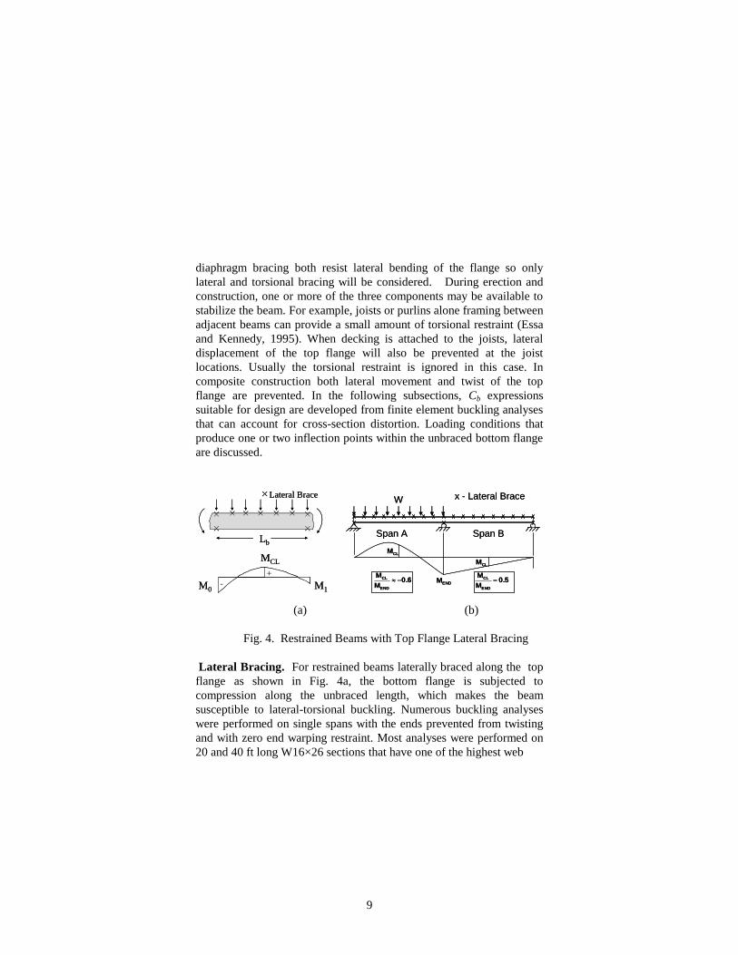
(a) (b)
Fig. 4. Restrained Beams with Top Flange Lateral Bracing
Lateral Bracing. For restrained beams laterally braced along the top
flange as shown in Fig. 4a, the bottom flange is subjected to
compression along the unbraced length, which makes the beam
susceptible to lateral-torsional buckling. Numerous buckling analyses
were performed on single spans with the ends prevented from twisting
and with zero end warping restraint. Most analyses were performed on
20 and 40 ft long W16×26 sections that have one of the highest web
W
Span A Span B
0.6M
M
END
CL
CLM
ENDM
CLM
0.5M
M
END
CL
x - Lateral BraceW
Span A Span B
0.6M
M
END
CL
CLM
ENDM
CLM
0.5M
M
END
CL
x - Lateral BraceLateral Brace
Lb
M0
MCL
M1-
+
Lateral Brace
Lb
M0
MCL
M1-
+
10
slenderness ratios for rolled shapes. This was done to maximize the
potential distortion so the conservative results would be applicable to
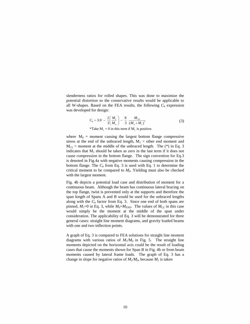
all W-shapes. Based on the FEA results, the following Cb expression
was developed for design:
(3)
where M0 = moment causing the largest bottom flange compressive
stress at the end of the unbraced length, M1 = other end moment and
MCL = moment at the middle of the unbraced length. The (*) in Eq. 3
indicates that M1 should be taken as zero in the last term if it does not
cause compression in the bottom flange. The sign convention for Eq.3
is denoted in Fig.4a with negative moments causing compression in the
bottom flange. The Cb from Eq. 3 is used with Eq. 1 to determine the
critical moment to be compared to M0. Yielding must also be checked
with the largest moment.
Fig. 4b depicts a potential load case and distribution of moment for a
continuous beam. Although the beam has continuous lateral bracing on
the top flange, twist is prevented only at the supports and therefore the
span length of Spans A and B would be used for the unbraced lengths
along with the Cb factor from Eq. 3. Since one end of both spans are
pinned, M1=0 in Eq. 3, while M0=MEND. The values of MCL in this case
would simply be the moment at the middle of the span under
consideration. The applicability of Eq. 3 will be demonstrated for three
general cases: straight line moment diagrams, and gravity loaded beams
with one and two inflection points.
A graph of Eq. 3 is compared to FEA solutions for straight line moment
diagrams with various ratios of M1/M0 in Fig. 5. The straight line
moments depicted on the horizontal axis could be the result of loading
cases that cause the moments shown for Span B in Fig. 4b or from beam
moments caused by lateral frame loads. The graph of Eq. 3 has a
change in slope for negative ratios of M1/M0, because M1 is taken
1
*
1
1 1
2 83.0
3 3 ( )
*Take M = 0 in this term if M is positive.
CLb
o o
M MC
M M M
11
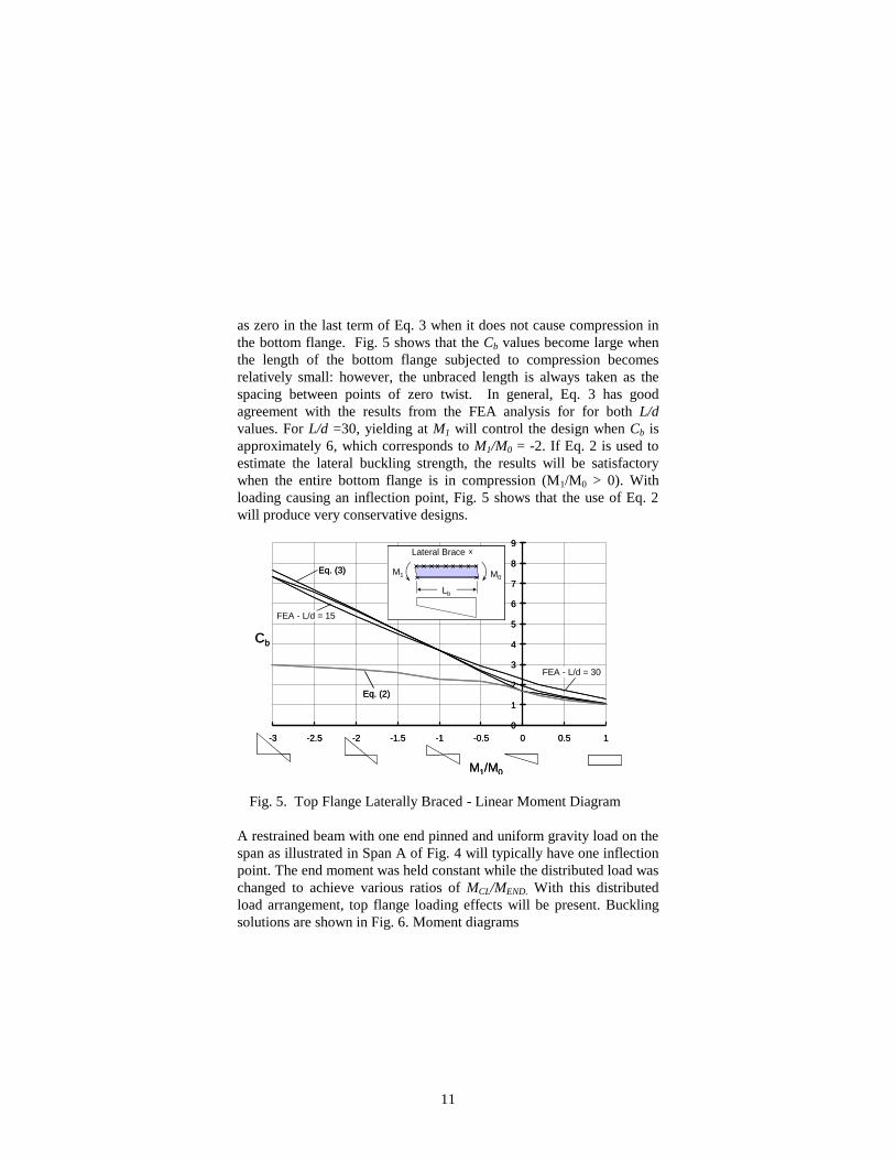
as zero in the last term of Eq. 3 when it does not cause compression in
the bottom flange. Fig. 5 shows that the Cb values become large when
the length of the bottom flange subjected to compression becomes
relatively small: however, the unbraced length is always taken as the
spacing between points of zero twist. In general, Eq. 3 has good
agreement with the results from the FEA analysis for for both L/d
values. For L/d =30, yielding at M1 will control the design when Cb is
approximately 6, which corresponds to M1/M0 = -2. If Eq. 2 is used to
estimate the lateral buckling strength, the results will be satisfactory
when the entire bottom flange is in compression (M1/M0 > 0). With
loading causing an inflection point, Fig. 5 shows that the use of Eq. 2
will produce very conservative designs.
Fig. 5. Top Flange Laterally Braced - Linear Moment Diagram
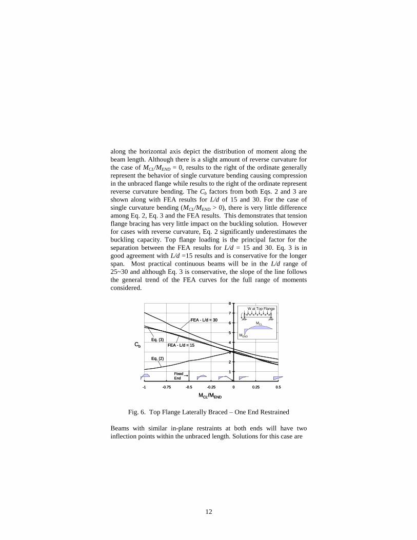
A restrained beam with one end pinned and uniform gravity load on the
span as illustrated in Span A of Fig. 4 will typically have one inflection
point. The end moment was held constant while the distributed load was
changed to achieve various ratios of MCL/MEND. With this distributed
load arrangement, top flange loading effects will be present. Buckling
solutions are shown in Fig. 6. Moment diagrams
0
1
2
3
4
5
6
7
8
9
-3 -2.5 -2 -1.5 -1 -0.5 0 0.5 1
M1/M0
Cb
FEA - L/d = 30
FEA - L/d = 15
Eq. (3) M0
Lateral Brace
Lb
M1
Eq. (2)
0
1
2
3
4
5
6
7
8
9
-3 -2.5 -2 -1.5 -1 -0.5 0 0.5 1
M1/M0
Cb
FEA - L/d = 30
FEA - L/d = 15
Eq. (3) M0
Lateral Brace
Lb
M1 M0
Lateral Brace
Lb
M1
Eq. (2)
12
along the horizontal axis depict the distribution of moment along the
beam length. Although there is a slight amount of reverse curvature for
the case of MCL/MEND = 0, results to the right of the ordinate generally
represent the behavior of single curvature bending causing compression
in the unbraced flange while results to the right of the ordinate represent
reverse curvature bending. The Cb factors from both Eqs. 2 and 3 are
shown along with FEA results for L/d of 15 and 30. For the case of
single curvature bending (MCL/MEND > 0), there is very little difference
among Eq. 2, Eq. 3 and the FEA results. This demonstrates that tension
flange bracing has very little impact on the buckling solution. However
for cases with reverse curvature, Eq. 2 significantly underestimates the
buckling capacity. Top flange loading is the principal factor for the
separation between the FEA results for L/d = 15 and 30. Eq. 3 is in
good agreement with L/d =15 results and is conservative for the longer
span. Most practical continuous beams will be in the L/d range of
25~30 and although Eq. 3 is conservative, the slope of the line follows
the general trend of the FEA curves for the full range of moments
considered.
Fig. 6. Top Flange Laterally Braced – One End Restrained
Beams with similar in-plane restraints at both ends will have two
inflection points within the unbraced length. Solutions for this case are
1
2
3
4
5
6
7
8
-1 -0.75 -0.5 -0.25 0 0.25 0.5
FEA - L/d = 30
FEA - L/d = 15
Eq. (3)
MCL/MEND
Cb
Fixed
End
W at Top Flange
MEND
MCL
Eq. (2)
1
2
3
4
5
6
7
8
-1 -0.75 -0.5 -0.25 0 0.25 0.5
FEA - L/d = 30
FEA - L/d = 15
Eq. (3)
MCL/MEND
Cb
Fixed
End
W at Top Flange
MEND
MCL
Eq. (2)
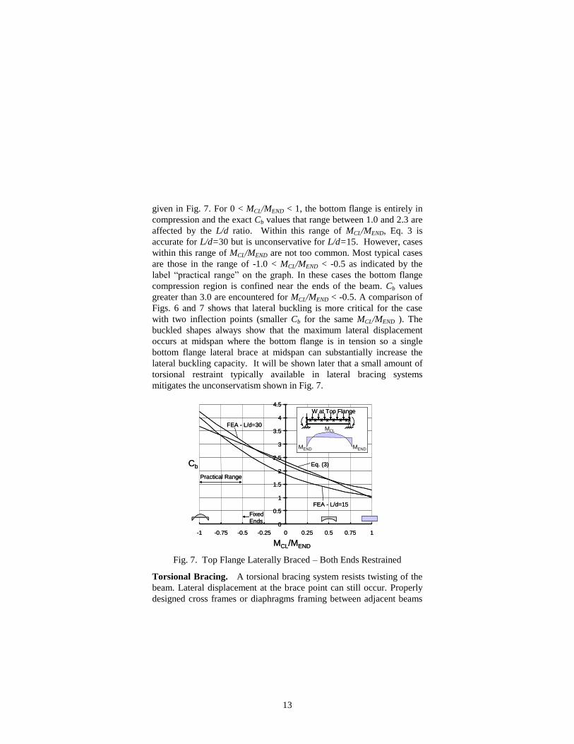
13
given in Fig. 7. For 0 < MCL/MEND < 1, the bottom flange is entirely in
compression and the exact Cb values that range between 1.0 and 2.3 are
affected by the L/d ratio. Within this range of MCL/MEND, Eq. 3 is
accurate for L/d=30 but is unconservative for L/d=15. However, cases
within this range of MCL/MEND are not too common. Most typical cases
are those in the range of -1.0 < MCL/MEND < -0.5 as indicated by the
label “practical range” on the graph. In these cases the bottom flange
compression region is confined near the ends of the beam. Cb values
greater than 3.0 are encountered for MCL/MEND < -0.5. A comparison of
Figs. 6 and 7 shows that lateral buckling is more critical for the case
with two inflection points (smaller Cb for the same MCL/MEND ). The
buckled shapes always show that the maximum lateral displacement
occurs at midspan where the bottom flange is in tension so a single
bottom flange lateral brace at midspan can substantially increase the
lateral buckling capacity. It will be shown later that a small amount of
torsional restraint typically available in lateral bracing systems
mitigates the unconservatism shown in Fig. 7.
Fig. 7. Top Flange Laterally Braced – Both Ends Restrained
Torsional Bracing. A torsional bracing system resists twisting of the
beam. Lateral displacement at the brace point can still occur. Properly
designed cross frames or diaphragms framing between adjacent beams
0
0.5
1
1.5
2
2.5
3
3.5
4
4.5
-1 -0.75 -0.5 -0.25 0 0.25 0.5 0.75 1
MCL/MEND
Cb
Fixed
Ends
FEA - L/d=15
FEA - L/d=30
Eq. (3)
W at Top Flange
MEND MEND
MCL
Practical Range
0
0.5
1
1.5
2
2.5
3
3.5
4
4.5
-1 -0.75 -0.5 -0.25 0 0.25 0.5 0.75 1
MCL/MEND
Cb
Fixed
Ends
FEA - L/d=15
FEA - L/d=30
Eq. (3)
W at Top Flange
MEND MEND
MCL
W at Top FlangeW at Top Flange
MEND MEND
MCL
Practical Range
14
act as torsional braces because they prevent beam twisting at those
locations. When the torsional brace is attached to either flange or just a
portion of the web depth, web cross-sectional distortion can occur that
diminishes the effectiveness of the torsional brace. Yura (1993) has
presented the following expression for the buckling strength of a
torsionally braced beam that accounts for the distortion, MT, based on
the solution developed by Taylor and Ojalvo (1966):
2
2 2 bb T y
T bu cr
T
C E IM C M
C
(4)
Cbu and Cbb are the two limiting Cb factors corresponding to an unbraced
beam (Eq. 2) and an effectively braced beam (buckling between discrete
braces); Mcr is given by Eq 1; CT is a top flange loading modification
factor: CT = 1.2 for top flange loading and CT = 1.0 for centroid loading;
and T is the equivalent effective continuous torsional brace (in-
k/radian/in. length) given by,
sec
1 1 1
T b and
3
sec 3.312
wE t
h (5)
where b = stiffness of the attached continuous brace, sec = cross-
section web stiffness per unit length of the beam, tw = thickness of web
and h = distance between flange centroids. sec accounts for cross- section
distortion. T is less than the smallest of b and sec. Web stiffeners can
be used to increase sec (Yura, 1993). If the effective brace stiffness is
very small, Eq. (4) converges to Eq. 1. If the unbraced length is long, Eq 4
will be dominated by the bracing term. Note that there is no beam length
variable in the bracing term. The bracing stiffness requirement in AISC
(2005) is based on Eq. 4 with the first term under the radical neglected
and MT set to the required design strength. When the torsional stiffness of
the brace itself is substantial, T =sec from Eq.5. Loaded pallets in
contact with the top flange of unstiffened support beams would represent
such a case. Eq. 4 was developed for single curvature loading
conditions. Studies undertaken on restrained beams indicated that some
15
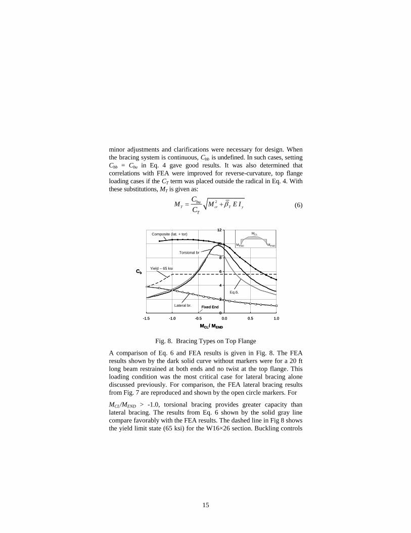
minor adjustments and clarifications were necessary for design. When
the bracing system is continuous, Cbb is undefined. In such cases, setting
Cbb = Cbu in Eq. 4 gave good results. It was also determined that
correlations with FEA were improved for reverse-curvature, top flange
loading cases if the CT term was placed outside the radical in Eq. 4. With
these substitutions, MT is given as:
2
T cr T y
bu
T
M M E IC
C (6)
Fig. 8. Bracing Types on Top Flange
A comparison of Eq. 6 and FEA results is given in Fig. 8. The FEA
results shown by the dark solid curve without markers were for a 20 ft
long beam restrained at both ends and no twist at the top flange. This
loading condition was the most critical case for lateral bracing alone
discussed previously. For comparison, the FEA lateral bracing results
from Fig. 7 are reproduced and shown by the open circle markers. For
MCL/MEND > -1.0, torsional bracing provides greater capacity than
lateral bracing. The results from Eq. 6 shown by the solid gray line
compare favorably with the FEA results. The dashed line in Fig 8 shows
the yield limit state (65 ksi) for the W16×26 section. Buckling controls
0
2
4
6
8
10
12
-1.5 -1.0 -0.5 0.0 0.5 1.0
MCL/ MEND
Cb
Fixed End
MEND MEND
MCLComposite (lat. + tor)
Yield – 65 ksi
Lateral br.
Torsional br
Eq.6.
0
2
4
6
8
10
12
-1.5 -1.0 -0.5 0.0 0.5 1.0
MCL/ MEND
Cb
Fixed End
MEND MEND
MCL
MEND MEND
MCLComposite (lat. + tor)
Yield – 65 ksi
Lateral br.
Torsional br
Eq.6.
16
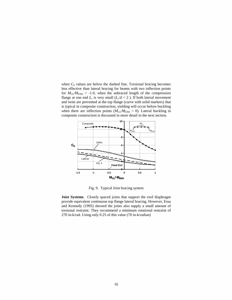
when Cb values are below the dashed line. Torsional bracing becomes
less effective than lateral bracing for beams with two inflection points
for MCL/MEND < -1.0, when the unbraced length of the compression
flange at one end Lc is very small (Lc/d < 2 ). If both lateral movement
and twist are prevented at the top flange (curve with solid markers) that
is typical in composite construction, yielding will occur before buckling
when there are inflection points (MCL/MEND < 0). Lateral buckling in
composite construction is discussed in more detail in the next section.
Fig. 9. Typical Joist bracing system
Joist Systems. Closely spaced joists that support the roof diaphragm
provide equivalent continuous top flange lateral bracing. However, Essa
and Kennedy (1995) showed the joists also supply a small amount of
torsional restraint. They recommend a minimum rotational restraint of
270 in-k/rad. Using only 0.25 of this value (70 in-k/radian)
0
2
4
6
8
10
12
-1.5 -1 -0.5 0 0.5 1
MCL/ MEND
Cb
Fixed End
MEND MEND
MCL
Joists
Composite
Eq. 3
Lateral
0
2
4
6
8
10
12
-1.5 -1 -0.5 0 0.5 1
MCL/ MEND
Cb
Fixed End
MEND MEND
MCL
MEND MEND
MCL
Joists
Composite
Eq. 3
Lateral
17
combined with zero lateral displacement at the joist locations, the 20 ft
beam (L/d = 15) restrained at both ends was
reanalyzed. Five joists at 4 ft spacing were used with deformations
controlled only at those five locations. The results are shown in Fig. 9
by the line with open markers. Recall that for this case with lateral only
that Eq. 3 gave some unconservative results as shown in Fig. 7. Those
results are reproduced in Fig. 9. The small torsional restraint has a
significant effect and Eq. 3 is now shown to be conservative.
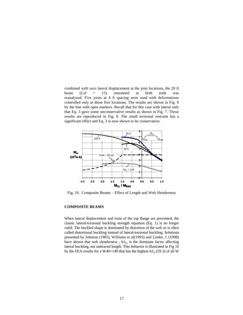
Fig. 10. Composite Beams – Effect of Length and Web Slenderness
COMPOSITE BEAMS
When lateral displacement and twist of the top flange are prevented, the
classic lateral-torsional buckling strength equation (Eq. 1) is no longer
valid. The buckled shape is dominated by distortion of the web so is often
called distortional buckling instead of lateral-torsional buckling. Solutions
presented by Johnson (1985), Williams et al(1993) and Linder, J. (1998)
have shown that web slenderness , h/tw, is the dominate factor affecting
lateral buckling, not unbraced length. This behavior is illustrated in Fig 10
by the FEA results for a W40×149 that has the highest h/tw (59.3) of all W
0
1
2
3
4
5
6
7
8
-3.0 -2.5 -2.0 -1.5 -1.0 -0.5 0.0 0.5 1.0
MCL / MEND
Mcr
(104in-k)
MEND MEND
MCL
100 ft
50 ft
30 ft
h/tw = 120
Yield – 65 ksi
0
1
2
3
4
5
6
7
8
-3.0 -2.5 -2.0 -1.5 -1.0 -0.5 0.0 0.5 1.0
MCL / MEND
Mcr
(104in-k)
0
1
2
3
4
5
6
7
8
-3.0 -2.5 -2.0 -1.5 -1.0 -0.5 0.0 0.5 1.0
MCL / MEND
Mcr
(104in-k)
MEND MEND
MCL
MEND MEND
MCL
100 ft
50 ft
30 ft
h/tw = 120
Yield – 65 ksi
18
shapes. Mcr for three different span lengths, 30, 50 and 100 ft, are shown
in the upper portions of the figure. For uniform compression along the
entire length of the unbraced bottom flange (MCL/MEND = 1.0), Mcr is
similar for all three lengths. There is some separation among the three
curves for moment diagrams with inflection points, i.e. negative
MCL/MEN. The solutions for the 30 and 50 ft lengths have been
terminated at MCL/MEN = -1.0 because of web shear buckling from the
very high applied loads. The largest Mcr was achieved with the 100 ft
beam. The plastic moment limit for 65 ksi steel is shown by the dashed
line so yielding will control rather than buckling except when there is
compression along the entire length of the bottom flange. Lateral
buckling can control if the web thickness of the 100 ft long W40×149 is
reduced by 50 percent (h/tw = 120) as shown by the curve with (x)
markers.
Most previous solutions for composite construction cited earlier were in
a graphical or tabular form and not easily suited for standard design. A
conservative lateral buckling solution for beams with twist and lateral
movement prevented at the top flange, MTB, is given by,
3sec
13900y y w
TB bT bT
T
EI I tM C C
C h
(7)
0.7
1.7 2 4.0CLbT
END
MC
M
(8)
Eq. 7 was obtained from Eq. 4 by ignoring the Mcr term, setting T =
sec. and replacing Cbb with CbT. The top flange loading factor is CT = 1.2. CbT was developed by comparing the critical moment from FEA
with the square root term in Eq. 7 as shown in Fig. 11. Eq. 8 is a lower
bound to all the cases, which include beams with one end restrained,
both ends restrained and a slender web. For rolled W shapes Eq. 7 can
be used to determine the lateral buckling capacity for the rare case
when the bottom flange is entirely in compression. For the common
situation when there are inflection points, yielding always control so
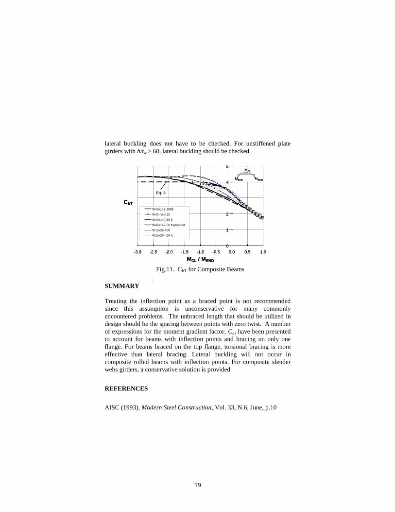
19
lateral buckling does not have to be checked. For unstiffened plate
girders with h/tw > 60, lateral buckling should be checked.
.
Fig.11. CbT for Composite Beams
SUMMARY
Treating the inflection point as a braced point is not recommended
since this assumption is unconservative for many commonly
encountered problems. The unbraced length that should be utilized in
design should be the spacing between points with zero twist. A number
of expressions for the moment gradient factor, Cb, have been presented
to account for beams with inflection points and bracing on only one
flange. For beams braced on the top flange, torsional bracing is more
effective than lateral bracing. Lateral buckling will not occur in
composite rolled beams with inflection points. For composite slender
webs girders, a conservative solution is provided
REFERENCES
AISC (1993), Modern Steel Construction, Vol. 33, N.6, June, p.10
0
1
2
3
4
5
-3.0 -2.5 -2.0 -1.5 -1.0 -0.5 0.0 0.5 1.0
MCL / MEND
CbT
W40x149-100ft
W40-h/t=120
W40x149-50 ft
W40x149-50 ft propped
W16x26-40ft
W16x26 - 20 ft
Eq. 8
MEND MEND
MCL
0
1
2
3
4
5
-3.0 -2.5 -2.0 -1.5 -1.0 -0.5 0.0 0.5 1.0
MCL / MEND
CbT
W40x149-100ft
W40-h/t=120
W40x149-50 ft
W40x149-50 ft propped
W16x26-40ft
W16x26 - 20 ft
Eq. 8
MEND MEND
MCL
MEND MEND
MCL
20
AISC (1995), Modern Steel Construction, Vol. 35, N.9, Sept., p.10
AISC(2005), Steel Construction Manual, Amer. Inst. of Steel Constr.,
13th Ed., Chicago.
CISC (2003), Advantage Steel, Can. Inst. of Steel Constr, N. 7, p. 4
Essa, H.S. and Kennedy, D.J.L.(1995), “Design of Steel beams in
Cantilever-Suspended-Span Construction”, J. of Struct. Engrg,
ASCE, Vol. 121, No. 11, pp. 1667-1673
Helwig, T.A. and Yura, J.A.(2008), "Shear Diaphragm Bracing of
Beams", J. of Struct. Engrg, ASCE, Vol. 134, No. 3, pp.348-363.
Johnson, R.P.(1985), “Continuous Composite Beams for Buildings”,
IABSE-ECCS Symposium Report – Steel in Buildings, Vol. 48,
Luxembourg, pp 195-202
Kirby, P.A. and Nethercot, D.A., (1979), Design for Structural Stability,
New York, John Wiley & Sons.
Linder, J. (1998),”Lateral Torsional Buckling of Composite Beams”, J.
Constructional Steel Research, 46: 1-3, Paper No. 289.
Nakamura, T. and Wakabayashi, M. (1981), “Lateral Buckling of Beams
Braced by Purlins", Inelastic Instability of Steel Structures and
Structural Elements, U.S. Japan Seminar, Y. Fujita and
T.V.Galambos, ed.
Nethercot, D.A. and Rocky, K.C.(1972), “A Unified Approach to the
Elastic Lateral Buckling of Beams”, AISC Eng. J., Vol. 9, No. 3, pp.
96-107.
Timoshenko, S.P. and Gere, J.M. (1961), Theory of Elastic Stability,
McGraw-Hill, New York.
Taylor, A.C., and Ojalvo, M., (1966), "Torsional Restraint of Lateral
Buckling," J. of Struct. Engrg, ASCE, ST2, April, pp. 115-129.
Williams, F.A., Jemah, A. and Lam, D.,(1993),”Distortional Buckling
Curves for Composite Beams”, J. of Struct. Engrg, ASCE, Vol. 119,
No. 7, July, 1993, pp. 2134-2149.
Yura, J.A. (1987), “Elements for Teaching Load and Resistance Factor
Design”, AISC, Chicago, IL, 30 pp.
Yura, J.A. (1993), “Fundamentals of Beam Bracing”, Proc. SSRC
Conf., “Is Your Structure Suitably Braced?” Milwaukee, Apr., 20
Updated: AISC Eng. J., Vol. 38, No. 1, 2001, pp. 11-26.