Embed Size (px)
Citation preview

VIBRATION ANALYSIS OF A TIRE
B.Sc. Engineering (Mechanical) Thesis
Authored by:
MUTASIM FUAD NUHASH
Student ID: 151413
MD. SHAMS MASUD
Student ID:151420
Supervised by:
PROF. DR. MD. ZAHID HOSSAIN
Head, Department of Mechanical and Production Engineering (MPE)
Islamic University of Technology (IUT)
DEPARTMENT OF MECHANICAL AND PRODUCTION ENGINEERING (MPE)
ISLAMIC UNIVERSITY OF TECHNOLOGY (IUT)
NOVEMBER 2019
ISLAMIC UNIVERSITY OF TECHNOLOGY (IUT)
ORGANISATION OF ISLAMIC COOPERATION (OIC)

i
CERTIFICATE OF RESEARCH
The thesis title “VIBRATION ANALYSIS OF A TIRE” submitted by
MUTASIM FUAD NUHASH (151413) and MD. SHAMS MASUD (151420) has
been accepted as satisfactory in partial fulfillment of the requirement for the Degree
of Bachelor of Science in Mechanical and Production Engineering on November, 2019.
Supervisor
_____________________________
PROF. DR. MD. ZAHID HOSSAIN
Head, Department of Mechanical and Production Engineering (MPE)
Islamic University of Technology (IUT)

ii
DECLARATION
This is to clarify that the work presented in this thesis is an outcome of the analysis,
simulation, experiment and research carried out by the author themselves under the
watchful supervision of Prof. Dr. Md. Zahid Hossain.
Authors
Mutasim Fuad Nuhash (151413)
Md. Shams Masud (151420)
Supervisor
Prof. Dr. Md. Zahid Hossain
Head, Department of Mechanical and Production Engineering (MPE)
Islamic University of Technology (IUT)

iii
ACKNOWLEDGEMNTS
We would like to express our deepest appreciation to our respectable supervisor Prof.
Dr. Md. Zahid Hossain, Head, Department of Mechanical and Production Engineering
(MPE) for his support, guidance, care, tutelage, motivation and patience throughout
the research period. We gratefully appreciate his support and encouragement which he
provided us throughout this academic year. Without his help and contribution our work
would not have been able to come to this stage as it is right now. We are indebted to
Nagib Mehfuz, Lecturer, Department of Mechanical and Production Engineering
(MPE) for his enormous support and guidance in making our reasearch work
successful. Apart from them we would like to thank each and every faculties of
Department of Mechanical and Production Engineering (MPE) for their knowledge,
assistance, motivation and care throughout the study period.
We also place on record, our sense of gratitude to one and all, who directly or
indirectly, have lent their hands in successful completion of this project work. Finally
we want to express our gratitude to Allah, The Almighty.
iv
ABSTRACT
Noise and vibration, transmitted from road to the body structure of a typical
automotive wheel, considered as an important parameter in automotive NVH (Noise,
Vibration and Harshness) performance optimization. Having a reliable and simple
finite element model of the wheel structure can significantly reduce time and cost of
design. Based on the results of experimental and numerical analyses, the effect of
inflation pressure is investigated on the behaviour of a tire in our work. The natural
frequencies are measured to describe free vibration of the tire. For observation of the
dynamic behavior, harmonic analysis is also carried out. Comparison between numer-
ical and experimental modal analyses shows an acceptable accuracy. Better
understanding of the complex tire characteristics will contribute to develop tire design
strategies to lower the tire/road vibration while less affecting other tire performances.
Keywords: Automobile Tire, Vibration, Modal Analysis, Tire Finite Element Analy-
sis, Harmonic Analysis, Inflation Pressure.

v
Table of Contents
1 Introduction ....................................................................................................... 1
1.1 Construction of a Tire ................................................................................ 2
1.2 Classification of Tire ................................................................................. 4
1.3 Tire Code ................................................................................................... 5
2 Literature Review .............................................................................................. 7
3 Methodology ................................................................................................... 11
3.1 Numerical Analysis.................................................................................. 11
3.1.1 Modeling .......................................................................................... 11
3.1.2 Material Properties ........................................................................... 11
3.1.3 Meshing ............................................................................................ 12
3.1.4 Boundary Conditions ........................................................................ 13
3.1.5 Modal Analysis ................................................................................. 14
3.1.6 Harmonic Analysis ........................................................................... 14
3.2 Experimental Analysis ............................................................................. 15
3.2.1 Determination of Material Properties ............................................... 15
3.2.2 Measurement of Natural Frequency (Initial Setup) .......................... 17
3.2.3 Measurement of Natural Frequency (Intermediate Setup) ............... 18
3.2.4 Measurement of Natural Frequency (Final Setup) ........................... 19
4 Results and Discussion .................................................................................... 20
4.1 Numerical Analysis.................................................................................. 20
4.1.1 Modal Analysis ................................................................................. 20
4.1.2 Harmonic Analysis ........................................................................... 24
4.2 Experimental Analysis ............................................................................. 25
4.3 Validation................................................................................................. 28
5 Conclusion ...................................................................................................... 29
6 Future Scope ................................................................................................... 30
7 References ....................................................................................................... 31
vi
List of Figures
Figure 1. Construction of a tire ............................................................................... 2
Figure 2. Radial tire ................................................................................................. 4
Figure 3. Non-radial tire .......................................................................................... 4
Figure 4. Side view of a tire and the most important information printed on a tire
sidewall ........................................................................................................................ 5
Figure 5. 2D model of the tire ............................................................................... 11
Figure 6. Meshed tire ............................................................................................. 13
Figure 7. Boundary conditions .............................................................................. 13
Figure 8. Overview of experimental setup ............................................................ 15
Figure 9. Main body and tread .............................................................................. 16
Figure 10. Sidewall ................................................................................................ 16
Figure 11. Bead bundle ......................................................................................... 16
Figure 12. L-shaped stand .................................................................................... 17
Figure 13. Mounting of the probe ......................................................................... 17
Figure 14. Aluminum foil strip attached with the tread ........................................ 17
Figure 15. Intermediate setup ................................................................................ 18
Figure 16. Final setup ............................................................................................ 19
Figure 17. Mode shapes for the inflation pressure of 23 psi ................................. 20
Figure 18. Mode shapes for inflation pressure of 29 psi ....................................... 21
Figure 19. Mode shapes for inflation pressure of 35 psi ....................................... 22
Figure 20. The natural frequencies of the tire under three different inflation
pressures ..................................................................................................................... 23
Figure 21. Harmonic frequency response for 23 psi ............................................. 24
Figure 22. Harmonic frequency response for 29 psi ............................................. 24
Figure 23. Harmonic frequency response for 35 psi ............................................. 25
Figure 24. Measured frequency for inflation pressure of 23 psi ........................... 26
Figure 25. Measured frequency for inflation pressure of 29 psi ........................... 26
Figure 26. Measured frequency for inflation pressure of 35 psi ........................... 27
Figure 27. The experimental natural frequencies of the tire under three different
inflation pressures ...................................................................................................... 27

vii
List of Tables
Table 1. Material properties of the tire .................................................................. 12
Table 2. The natural frequencies of the tire under three different inflation
pressures ..................................................................................................................... 23
Table 3. Experimental data .................................................................................... 25
Table 4. Comparison of numerical and experimental first natural frequency ....... 28

1
1 Introduction
Tire is a rubber member which gives the cushion to the automobile. It is the only
means to transfer forces between the road and vehicle. It is required to produce the
forces necessary to control the vehicle, and hence, they are an important component of
a vehicle. It performs mainly three functions:
1) Support vertical loads while cushioning against shocks.
2) Develop / transfer longitudinal forces for acceleration and braking.
3) Develop lateral forces for cornering power for smooth steering.
Pneumatic tires greatly influence the riding comfort and noise level in cars.
Tire/road interaction is a significant operative parameter for vehicle manufacturers,
because tires are the only member of an automotive having contact with road. The
undesirable transmitted vibrations negatively influence on passengers and would be
annoying in long term. The previous studies show that in vehicle dynamics interaction
of tire resonance frequencies with road disturbance and surrounding air can easily
magnify the level of interior noise and vibrations [1]. Hence, the NVH (Noise, Vibra-
tion and Harshness) performance of a vehicle has become an important parameter in
automotive structural dynamics that need to be carefully designed and optimized in
early phase of design [1-3].
The structural vibrations of the tire are generated by the interactions between tire
and road that are created by road irregularities and brake torque changes. Vibrations
would be transmitted from tire to the automotive body through suspension system [4].
Type of vibration depends on the plane that vibration is studied on and it could be
bending, longitudinal and torsion. The inflation pressure also plays a vital role in the
behavioral characteristics of a tire. It stresses the structure in such a way that any ex-
ternal force causing deformation in the carcass results in a tire reaction force. The
characteristics of the tire depend not only on the operating conditions, but on the type
of construction as well. So, in order to perform our research work, a clear insight into
vibration, tire construction, tire properties are necessary.

2
1.1 Construction of a Tire
A tire is an advanced engineering product made of rubber and a series of synthetic
materials cooked together. They are combined in such a way to achieve different ob-
jectives. The objective may be performance optimization, traction maximization, or
better rolling resistance. Fiber, textile, and steel cords are some of the components that
go into the tire’s inner liner, body plies, bead bundle, belts, sidewalls, and tread. Figure
1 illustrates a sample of tire interior components and their arrangement.
Figure 1. Construction of a tire [5]
The main components of a tire are explained below:
Bead or bead bundle is a loop of high strength steel cable coated with rubber. It gives
the tire the strength it needs to stay seated on the wheel rim and to transfer the tire
forces to the rim.
Inner layers are made up of different fabrics, called plies. The most common ply fabric
is polyester cord. The top layers are also called cap plies. Cap plies are polyesteric
fabric that help hold everything in place.
3
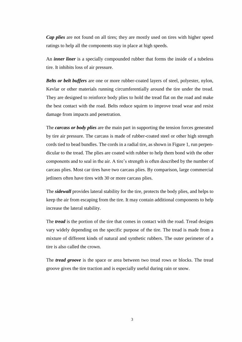
Cap plies are not found on all tires; they are mostly used on tires with higher speed
ratings to help all the components stay in place at high speeds.
An inner liner is a specially compounded rubber that forms the inside of a tubeless
tire. It inhibits loss of air pressure.
Belts or belt buffers are one or more rubber-coated layers of steel, polyester, nylon,
Kevlar or other materials running circumferentially around the tire under the tread.
They are designed to reinforce body plies to hold the tread flat on the road and make
the best contact with the road. Belts reduce squirm to improve tread wear and resist
damage from impacts and penetration.
The carcass or body plies are the main part in supporting the tension forces generated
by tire air pressure. The carcass is made of rubber-coated steel or other high strength
cords tied to bead bundles. The cords in a radial tire, as shown in Figure 1, run perpen-
dicular to the tread. The plies are coated with rubber to help them bond with the other
components and to seal in the air. A tire’s strength is often described by the number of
carcass plies. Most car tires have two carcass plies. By comparison, large commercial
jetliners often have tires with 30 or more carcass plies.
The sidewall provides lateral stability for the tire, protects the body plies, and helps to
keep the air from escaping from the tire. It may contain additional components to help
increase the lateral stability.
The tread is the portion of the tire that comes in contact with the road. Tread designs
vary widely depending on the specific purpose of the tire. The tread is made from a
mixture of different kinds of natural and synthetic rubbers. The outer perimeter of a
tire is also called the crown.
The tread groove is the space or area between two tread rows or blocks. The tread
groove gives the tire traction and is especially useful during rain or snow.

4
1.2 Classification of Tire
Tires are divided in two classes: radial and non-radial, depending on the angle be-
tween carcass metallic cords and the tire-plane. Each type of tire construction has its
own set of characteristics that are the key to its performance.
The radial tire is constructed with reinforcing steel cable belts that are assembled in
parallel and run side to side, from one bead to another bead at an angle of 90° to the
circumferential centerline of the tire. This makes the tire more flexible radially, which
reduces rolling resistance and improves cornering capability. The tire being used for
our research work is a radial one.
The non-radial tires are also called bias-ply and cross-ply tires. The plies are layered
diagonal from one bead to the other bead at about a 30° angle, although any other
angles may also be applied. One ply is set on a bias in one direction as succeeding plies
are set alternately in opposing directions as they cross each other. The ends of the plies
are wrapped around the bead wires, anchoring them to the rim of the wheel.
The most important difference in the dynamics of radial and non-radial tires is their
different ground sticking behavior when a lateral force is applied on the wheel. The
radial tire, shown in Figure 2, flexes mostly in the sidewall and keeps the tread flat on
the road. The bias-ply tire, shown in Figure 3 has less contact with the road as both
tread and sidewalls distort under a lateral load.
Figure 2. Radial tire [5] Figure 3. Non-radial tire [5]
The radial arrangement of carcass in a radial tire allows the tread and sidewall act
independently. The sidewall flexes more easily under the weight of the vehicle. So,
5
more vertical deflection is achieved with radial tires. As the sidewall flexes under the
load, the belts hold the tread firmly and evenly on the ground and reduces tread scrub.
In a cornering maneuver, the independent action of the tread and sidewalls keeps the
tread flat on the road. This allows the tire to hold its path. Radial tires are the preferred
tire in most applications today.
The cross arrangement of carcass in bias-ply tires allows it act as a unit. When the
sidewalls deflect or bend under load, the tread squeezes in and distorts. This distortion
affects the tireprint and decrease traction. Because of the bias-ply inherent construction,
sidewall strength is less than that of a radial tire’s construction and cornering is less
effective.
1.3 Tire Code
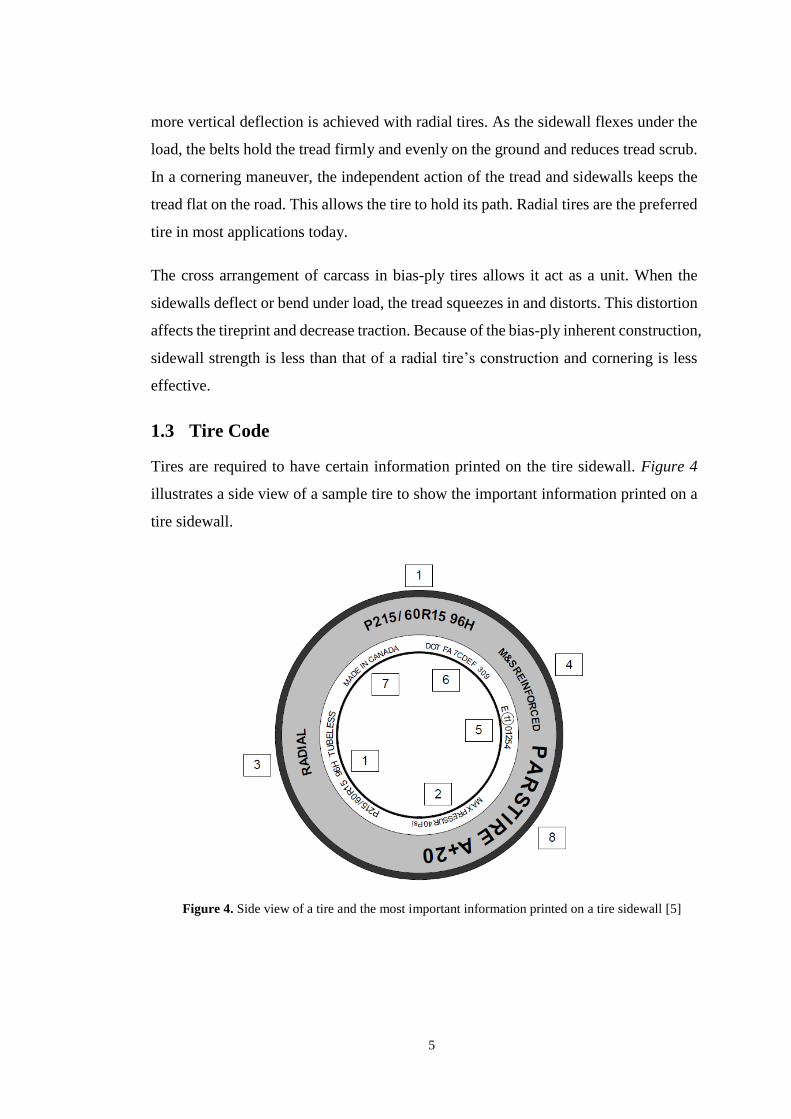
Tires are required to have certain information printed on the tire sidewall. Figure 4
illustrates a side view of a sample tire to show the important information printed on a
tire sidewall.
Figure 4. Side view of a tire and the most important information printed on a tire sidewall [5]
6
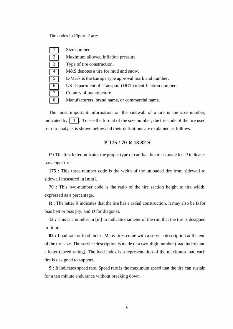
The codes in Figure 2 are:
1 Size number.
2 Maximum allowed inflation pressure.
3 Type of tire construction.
4 M&S denotes a tire for mud and snow.
5 E-Mark is the Europe type approval mark and number.
6 US Department of Transport (DOT) identification numbers.
7 Country of manufacture.
8 Manufacturers, brand name, or commercial name.
The most important information on the sidewall of a tire is the size number,
indicated by 1 . To see the format of the size number, the tire code of the tire used
for our analysis is shown below and their definitions are explained as follows.
P 175 / 70 R 13 82 S
P : The first letter indicates the proper type of car that the tire is made for. P indicates
passenger tire.
175 : This three-number code is the width of the unloaded tire from sidewall to
sidewall measured in [mm].
70 : This two-number code is the ratio of the tire section height to tire width,
expressed as a percentage.
R : The letter R indicates that the tire has a radial construction. It may also be B for
bias belt or bias ply, and D for diagonal.
13 : This is a number in [in] to indicate diameter of the rim that the tire is designed
to fit on.
82 : Load rate or load index. Many tires come with a service description at the end
of the tire size. The service description is made of a two-digit number (load index) and
a letter (speed rating). The load index is a representation of the maximum load each
tire is designed to support.
S : It indicates speed rate. Speed rate is the maximum speed that the tire can sustain
for a ten minute endurance without breaking down.

7
2 Literature Review
Tire is the most representative product of composite structures. It is a very complex
system to study [l]. The tire is under vertical load, lateral force, driving force, braking
force, and other loads when the car is in motion. Meanwhile, the tire frictions and
impacts with the ground dramatically, which causes greater stress, strain, and vibration.
Tires and suspension system absorbs a part of the vibration, the remainder affects com-
fort, handling stability, safety of vehicles, and produces noise, and even make the tires
have a resonance. To improve the vibration and noise characteristics of the tire is an
important way to enhance the driving performance of vehicles. Thus, it is necessary to
study vibration characteristics of tires and the relationship between the vibration
modes and the vehicle vibration. Much research has been conducted on the vibration
characteristics of radial tires.
Experimental modal analysis of a non-rotating tire for two boundary conditions is
presented in [6]. The tire was excited by a hammer and the responses were measured
in tangential and radial direction with accelerometers. Mode shapes and frequencies
were assessed from the measured frequency response functions. These experimental
results were compared with the modes of a theoretical tire ring model, where tire was
modeled as a circular beam that was able to deform in radial and tangential direction.
He obtained smooth and accurate mode shapes by measuring the responses at only ten
points on the tire circumference. The modes of the free tire were symmetric. Each
mode was double, that is for each natural frequency two identical mode shapes exist.
The only difference in the two identical mode shapes was an offset in the angular po-
sition of the (anti-)nodes.
The investigation into tire–road interaction and radial tire vibrations for tire–road
noise characterization was done in [7]. Experimental measurements were performed
on a rolling smooth tire with test laboratory facilities. Both tread band and sidewall
responses of the tire were measured and compared to each other. High concentration
of vibrations was observed in the vicinity of the contact area.
8
Lopez et al. [8] examined an approach to model the vibrations of deformed rotating
tire in the lower frequency range. Determining the eigenvalues and eigenmodes of a
detailed FE-model of the tire and then using these to construct a modal base of the tire
seems a computationally efficient way of calculating the dynamic response of the tire
taking its complex build-up into account. The presented methodology allows for the
calculation of the response of the rotating tire in a fixed (Eulerian) reference frame,
including the influence of gyroscopic and centrifugal forces.
Lee and Kim [9] modeled the tire to a 7-degree of freedom system according to
design factor, and vibration energy change due to design factor change was examined.
Using the model, it was concluded that the side part, which transmits the vibration of
road surface (bump) to the rim, has an important effect on vibration energy, and it can
be proposed as a solution for reducing vibration energy when a tire passes the cleat.
Guan et al. [10] used MSC.MARC software for the modal analysis of practical
structure of 195/60R14 radial tire. The model was employed to simulate complex
multilayer rubber-cord composites. The model considers the geometric non-linearity
and the non-linear boundary conditions from tire-rim contact and tire-road contact. It
was found that first mode shape has two lobes, the second mode shape has three lobes,
and so on. Changes of the inflation pressure did not affect the mode shape, but the
natural frequency of higher mode shape was sensitive to the change of the inflation
pressure.
Duhamel, Erlicher and Nguyen [11] applied the recursive method for the
computation of tire vibrations for medium and high frequencies. They described the
recursive method for curve periodic structures and its application to the computation
of frequency response functions is also explained.
The analysis for a truck tire has also been carried out in [12]. The aim of this work
was to investigate the possibility of building a numerical model that simulates the
vibration behavior of a truck tire at low-mid frequencies. The simulation was

9
performed on a three-dimension geometric model of truck tire, in this case all the parts
of truck tire influence on the vibration mechanism.
The model of a wheel with a reinforced tyre was considered in [13]. Then, the
equations of motion and the conditions on the boundary of an unknown in advance
contact area were obtained. Next, the vibrations of unloaded non-rotating, unloaded
rotating , loaded non-rotating and loaded rotating tyre were considered. The results
for the unloaded non-rotating and loaded non-rotating cases were compared with
experiment.
Abd_Elsalam, Gohary and El-Gamal [14] investigated some aspects in the
experimental modal analysis of the tires such as the type of support of the tire (elastic
light band, soft springs carrying the assembly, soft cushion, free support in axial
direction), the means of excitation, he selection of the sensors to reduce the additional
mass and stiffness of the tested object as much as possible. The response of the tire
was quite similar to the response of viscously damped mass system subjected to an
impulse excitation for impulse force which is provided by the impact hammer. The
results showed that the system modal parameters can be obtained respective of loading
or unloading conditions with a maximum difference of 1.992% for frequency values
and 3.66% for damping values. This study had a practical value for the description of
mechanical properties of tires.
Karakus, Cavus and Colakoglu [15] analyzed the free vibration of a radial pneumatic
tire, P175/70R13 using solid finite element models (FEM) . Effects inflation pressure,
vertical load and co-efficient of friction of the tire to natural frequencies were also
studied. Experiments were run under certain conditions to check the accuracy of the
numerical model. The natural frequencies were measured to describe free vibration
and vibration of the tire contacted by ground, using a damping monitoring method.
According to the results, the inflation pressure was the most effective parameter on the
natural frequencies which increase with increased inflation pressure. On the other hand,
the effects of the coefficient of friction and the vertical load were different and much
more complex on the first six natural frequencies.

10
Farahani and Mahjoob [16] validated finite element model of an automotive wheel
structure by experimental modal analysis. Validation was conducted via frequency
response functions and resonance frequencies. The shift of resonance frequencies in
FRF diagram was also studied and discussed for different conditions. FEM model of
the tire was also developed consisting of a Neo-Hookean model for the tire and linear
elastic model for the rim.
Our work aims to study the vibration characteristics of a 175/70 R13 tire. We have
to analyze the characteristics both numerically and experientially. Modal analysis as
well as harmonic analysis will be performed. The effect of inflation pressure will be
taken into consideration.

11
3 Methodology
3.1 Numerical Analysis
3.1.1 Modeling
The modelling was done on SOLIDWORKS 2016 based on the measurements ex-
tracted from commercially available tire (Bridgestone P175/70R13 82S). For the sim-
plification of modelling, inner layer, belt buffer, carcass and inner liner are considered
to be a single composite part. We will be calling it main body throughout our report.
So, there will be mainly four different parts in this composite tire model: treads, side-
wall, bead bundle and main composite body.
Figure 5. 2D model of the tire
3.1.2 Material Properties
For our analysis, we have considered tread as isentropic (the material properties
stays constant in all directions) and sidewall, main body and bead bundle as orthotropic
(the material properties changes in orthogonal directions only). The material properties
were collected from a previous work for the same tire [15] as the properties could not
be measured experimentally.
12
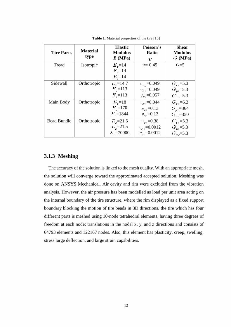
Table 1. Material properties of the tire [15]
Tire Parts
Material
type
Elastic
Modulus
E (MPa)
Poisson’s
Ratio
Shear
Modulus
(MPa)
Tread Isotropic =14
=14
=14
= 0.45
=5
Sidewall Orthotropic =14.7
=113
=113
=0.049
=0.049
=0.057
=5.3
=5.3
=5.3
Main Body Orthotropic =18
=170
=1844
=0.044
=0.13
=0.13
=6.2
=364
=350
Bead Bundle Orthotropic =21.5
=21.5
=70000
=0.38
=0.0012
=0.0012
=5.3
=5.3
=5.3
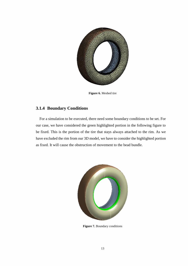
3.1.3 Meshing
The accuracy of the solution is linked to the mesh quality. With an appropriate mesh,
the solution will converge toward the approximated accepted solution. Meshing was
done on ANSYS Mechanical. Air cavity and rim were excluded from the vibration
analysis. However, the air pressure has been modelled as load per unit area acting on
the internal boundary of the tire structure, where the rim displayed as a fixed support
boundary blocking the motion of tire beads in 3D directions. the tire which has four
different parts is meshed using 10-node tetrahedral elements, having three degrees of
freedom at each node: translations in the nodal x, y, and z directions and consists of
64793 elements and 122167 nodes. Also, this element has plasticity, creep, swelling,
stress large deflection, and large strain capabilities.
13
Figure 6. Meshed tire
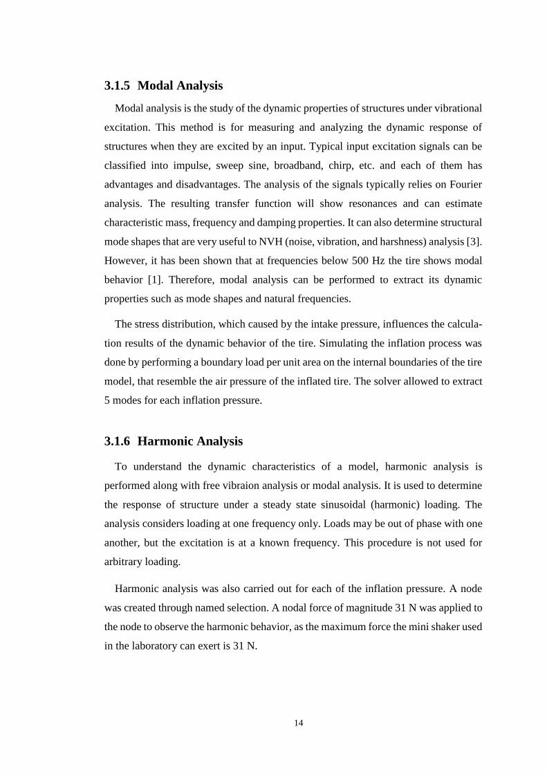
3.1.4 Boundary Conditions
For a simulation to be executed, there need some boundary conditions to be set. For
our case, we have considered the green highlighted portion in the following figure to
be fixed. This is the portion of the tire that stays always attached to the rim. As we
have excluded the rim from our 3D model, we have to consider the highlighted portion
as fixed. It will cause the obstruction of movement to the bead bundle.
Figure 7. Boundary conditions
14
3.1.5 Modal Analysis
Modal analysis is the study of the dynamic properties of structures under vibrational
excitation. This method is for measuring and analyzing the dynamic response of
structures when they are excited by an input. Typical input excitation signals can be
classified into impulse, sweep sine, broadband, chirp, etc. and each of them has
advantages and disadvantages. The analysis of the signals typically relies on Fourier
analysis. The resulting transfer function will show resonances and can estimate
characteristic mass, frequency and damping properties. It can also determine structural
mode shapes that are very useful to NVH (noise, vibration, and harshness) analysis [3].
However, it has been shown that at frequencies below 500 Hz the tire shows modal
behavior [1]. Therefore, modal analysis can be performed to extract its dynamic
properties such as mode shapes and natural frequencies.
The stress distribution, which caused by the intake pressure, influences the calcula-
tion results of the dynamic behavior of the tire. Simulating the inflation process was
done by performing a boundary load per unit area on the internal boundaries of the tire
model, that resemble the air pressure of the inflated tire. The solver allowed to extract
5 modes for each inflation pressure.
3.1.6 Harmonic Analysis
To understand the dynamic characteristics of a model, harmonic analysis is
performed along with free vibraion analysis or modal analysis. It is used to determine
the response of structure under a steady state sinusoidal (harmonic) loading. The
analysis considers loading at one frequency only. Loads may be out of phase with one
another, but the excitation is at a known frequency. This procedure is not used for
arbitrary loading.
Harmonic analysis was also carried out for each of the inflation pressure. A node
was created through named selection. A nodal force of magnitude 31 N was applied to
the node to observe the harmonic behavior, as the maximum force the mini shaker used
in the laboratory can exert is 31 N.

15
3.2 Experimental Analysis
The basic idea of experimental modal analysis is the excitation of a structure by a
measurable dynamic force and measuring the dynamic responses at several points of
the structure. The obtained Frequency Response Functions (FRF) show the resonance
frequencies of the structure. The mode shapes result from the amplitude of vibration
at the resonance frequencies at several points of the structure.
Bridgestone P175/70R13 82S tire, which has maximum vertical load capacity of
4660N (475 kg), was used for our analysis. A ECL 202e sensor was used to sense the
exications and a GW Instek oscilloscope was used to display the results.
Figure 8. Overview of experimental setup
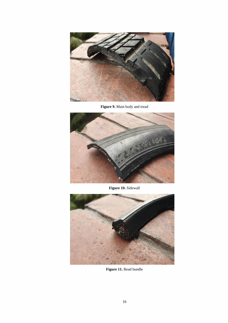
3.2.1 Determination of Material Properties
To determine the material properties of the tire, the tire was cut into various sections.
The standard specimen for material testing could not be prepared due to the difficulties
in separation of the parts of the tire. But the laboratory facilities were not enough to
determine the properties. To mitigate this problem, the material properties collected
from a study [15] of the same model of the tire are used for the analysis.
16
Figure 9. Main body and tread
Figure 10. Sidewall
Figure 11. Bead bundle

17
3.2.2 Measurement of Natural Frequency (Initial Setup)
For the free vibration analysis, the tire was fixed at the rear wheel of the car, where
the car was upheld with a jackscrew. A L-shaped stand was built to hold the probe of
the sensor to provide stability to the sensor.
Figure 12. L-shaped stand
The probe was located between 4 mm from the tire. The sensor could sense only non-
ferrous metal. So, an aluminum cross section of 20mm x 20mm was cut with a scissor.
Then the foil was attached to the tire with the help of Super Glue.
Figure 14. Aluminum foil strip attached with the tread
Figure 13. Mounting of the probe

18
The vibration was induced in the tire using a small steel hammer. The ECL 202e sensor
measures the vibration and produces an electrical signal which is received in the oscil-
loscope.
The problem with that setup was the presence of the vertical load or self-weight exerted
by the car which hampered the determination of our desired results.
3.2.3 Measurement of Natural Frequency (Intermediate Setup)
This time we hung the tire with nylon cable from four stands fixed on a table. The
stress distribution in each cable was maintained equal as far as possible. The setup was
able to provide the necessary support to the tire for free vibration analysis. Aluminum
strip was attached to the tire. Through a small hammer, vibration was induced and the
results were processed and presented through the sensor and the oscilloscope respec-
tively.
The shortcoming of the setup was the table’s instability which affected the vibration
of the tire also. Thus the results achieved were not desirable.
Figure 15. Intermediate setup
19
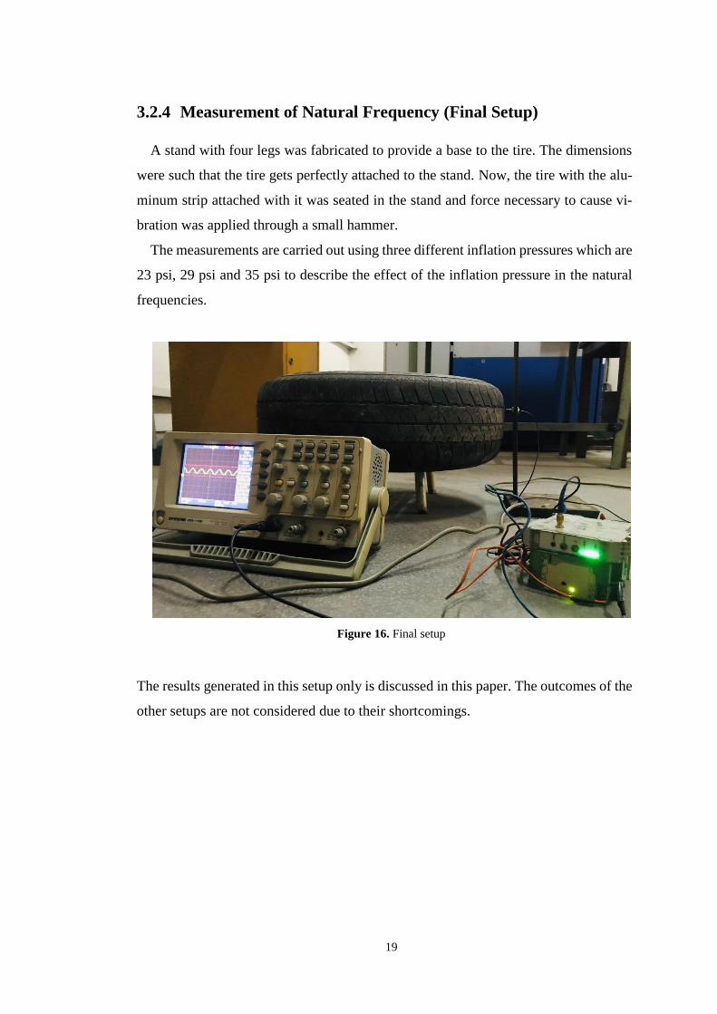
3.2.4 Measurement of Natural Frequency (Final Setup)
A stand with four legs was fabricated to provide a base to the tire. The dimensions
were such that the tire gets perfectly attached to the stand. Now, the tire with the alu-
minum strip attached with it was seated in the stand and force necessary to cause vi-
bration was applied through a small hammer.
The measurements are carried out using three different inflation pressures which are
23 psi, 29 psi and 35 psi to describe the effect of the inflation pressure in the natural
frequencies.
Figure 16. Final setup
The results generated in this setup only is discussed in this paper. The outcomes of the
other setups are not considered due to their shortcomings.
20
4 Results and Discussion
4.1 Numerical Analysis
4.1.1 Modal Analysis
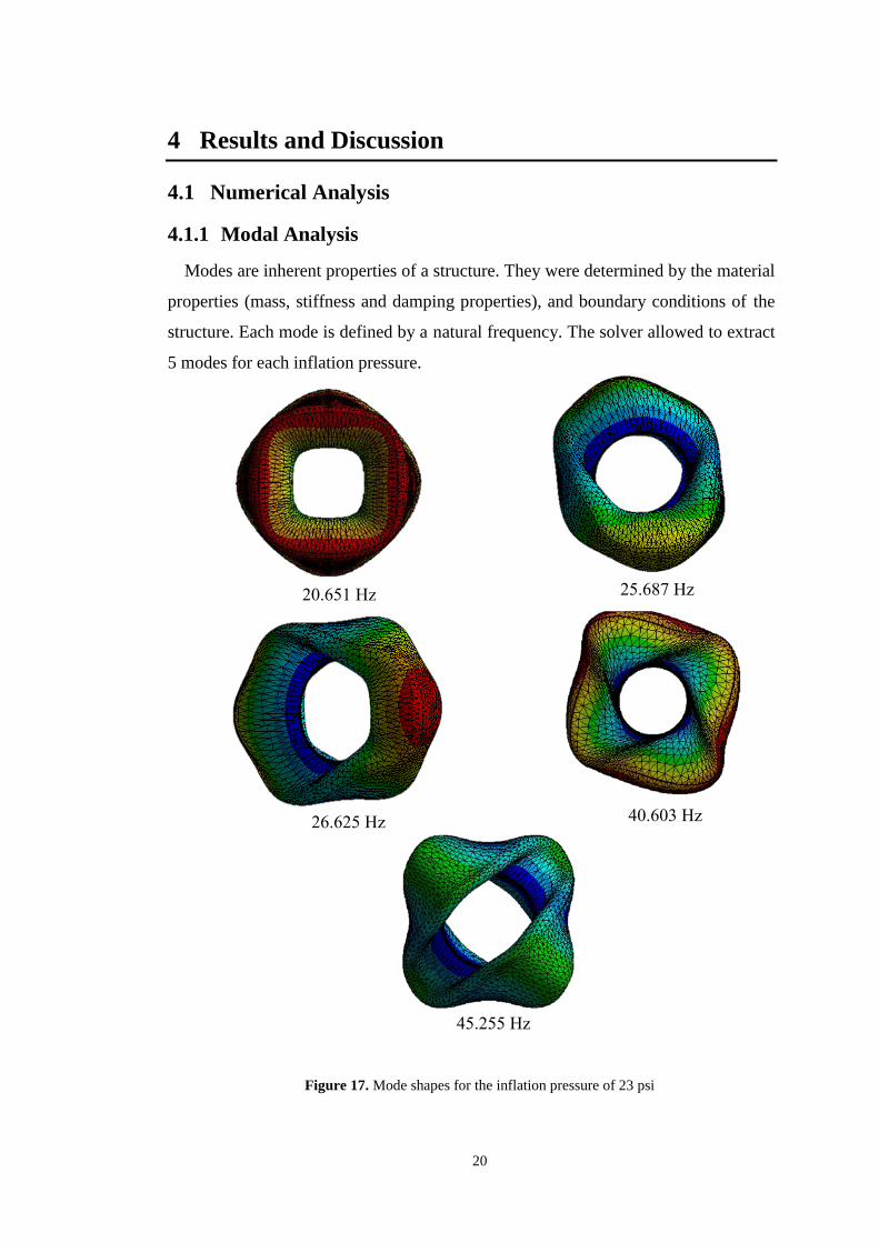
Modes are inherent properties of a structure. They were determined by the material
properties (mass, stiffness and damping properties), and boundary conditions of the
structure. Each mode is defined by a natural frequency. The solver allowed to extract
5 modes for each inflation pressure.
Figure 17. Mode shapes for the inflation pressure of 23 psi
20.651 Hz 25.687 Hz
26.625 Hz 40.603 Hz
45.255 Hz

21
Figure 18. Mode shapes for inflation pressure of 29 psi
21.814 Hz 26.795 Hz
27.764 Hz 40.261 Hz
47.036 Hz

22
Figure 19. Mode shapes for inflation pressure of 35 psi
22.673 Hz 27.666 Hz
28.667 Hz 39.803 Hz
47.922 Hz

23
Modal analysis is carried out using 3D numerical model for each inflation pressure.
According to the results, the natural frequencies increase with increased inflation pres-
sure. The results are tabulated below:
Table 2. The natural frequencies of the tire under three different inflation pressures
Mode
Natural Frequency (Hz)
Pressure
(23 psi)
Pressure
(29 psi)
Pressure
(35 psi)
1 20.651 21.814 22.673
2 25.687 26.795 27.666
3 26.625 27.764 28.667
4 39.803 40.261 40.603
5 45.255 47.036 47.922
6 46.345 47.321 48.599
Figure 20. The natural frequencies of the tire under three different inflation pressures
Inflation Pressure (psi)
22 24 26 28 30 32 34 36
Nat
ural
Fre
quen
cy (
Hz)
15
20
25
30
35
40
45
50
Mode 1
Mode 2
Mode 2
Mode 4
Mode 5
Mode 6

24
4.1.2 Harmonic Analysis
The analysis shows if the peak amplitudes are at the modal frequencies or not. The
following frequency response graphs were generated for corresponding inflation pres-
sure to show variation in deformation:
Figure 21. Harmonic frequency response for 23 psi
Figure 22. Harmonic frequency response for 29 psi
25
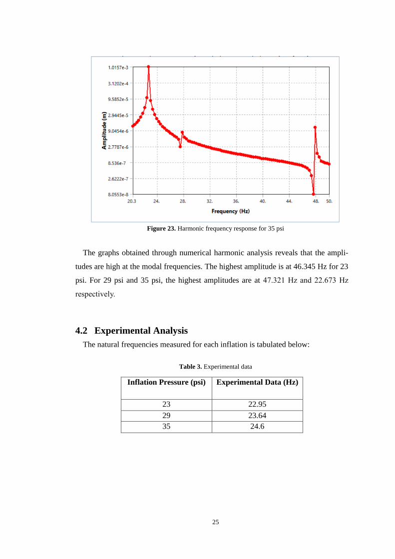
Figure 23. Harmonic frequency response for 35 psi
The graphs obtained through numerical harmonic analysis reveals that the ampli-
tudes are high at the modal frequencies. The highest amplitude is at 46.345 Hz for 23
psi. For 29 psi and 35 psi, the highest amplitudes are at 47.321 Hz and 22.673 Hz
respectively.
4.2 Experimental Analysis
The natural frequencies measured for each inflation is tabulated below:
Table 3. Experimental data
Inflation Pressure (psi) Experimental Data (Hz)
23 22.95
29 23.64
35 24.6

26
Figure 24. Measured frequency for inflation pressure of 23 psi
Figure 25. Measured frequency for inflation pressure of 29 psi

27
Figure 26. Measured frequency for inflation pressure of 35 psi
Figure 27. The experimental natural frequencies of the tire under three different inflation pressures
Our findings demonstrate that the frequency increases with the increasing pressure.
The relationship is almost linear.
Inflature Pressure (psi)
22 24 26 28 30 32 34 36
Nat
ura
l F
req
uen
cy (
Hz)
22.8
23.0
23.2
23.4
23.6
23.8
24.0
24.2
24.4
24.6
24.8

28
4.3 Validation
The discrepancy between the numerical and experimental data is negligible. The
variation is due to the lack of soundproof environment during the measurement of ex-
perimental data. Besides, the base used for holding the tire could not be properly fixed.
This factor may be responsible for the results achieved.
Table 4. Comparison of numerical and experimental first natural frequency
Inflation
Pressure (psi)
Numerical Data
(Hz)
Experimental
Data (Hz)
Error (%)
23 20.651 22.95 10.02
29 21.814 23.64 7.72
35 22.673 24.6 7.83
In the case of numerical analysis, the inaccuracy in the modeling may play a vital role
in the unexpected results. The dimensions are tried to kept as similar as possible to an
actual tire. The variation may also be due to our inability to get the right mechanical
properties of the compound materials. As the tire manufacturing companies keep this
information to themselves, it is very difficult to make an exact model of the commer-
cially available tire.

29
5 Conclusion
We have studied an automotive wheel vibration behavior using experimental and
numerical modal analysis on a commercially available tire. Harmonic analysis is per-
formed only numerically. Our work has led to the conclusion that:
1) The natural frequency increases with the increase of inflation pressure.
2) The developed finite element mode is verified with experimental results via
comparison of resonance frequencies and mode shapes. The amount of error
is around 10%.
3) Although the initial simulation results show some deviation from experi-
mental measurements, still the dynamic behavior of the model is taking the
same pattern compared to measurement. The potential reasons for this divi-
sion can be referred to the low mesh quality, which has effect on the accuracy
in the first step of the simulation, this lead to an error in the stress computa-
tions especially in the hot spot areas like belts, and ply, which has even lower
mesh quality.
4) The harmonic analysis demonstrates that the amplitudes are high at the
modal frequencies.
30
6 Future Scope
The study is the first step towards enhancing our understanding towards various
factors affecting the vibration of a tire. Further work needs to be carried out to estimate
the other parameters’ effect on the tire vibration. To improve stability and reduce vi-
bration of the tire, analysis can be performed by changing the boundary conditions.
Tire can be contacted by the ground to have a more realistic analysis. In this case, the
effect of coefficient of friction will also be accountable. The tire can also be tested by
mounting to the car to have the effect of the self-weight of the car included. The effect
of rotational speed can be considered for the monitoring of the tire behavior under
continuous loads. The prospect of being able to understand and reduce vibration,
should serve as a continuous incentive for future research.
31
7 References
[1] P. Kindt, P. Sas and W. Desmet, “Three-dimensional Ring Model for the Predic-
tion of the Tire Structural Dynamic Behavior”, In Proceedings of the International
Conference on Noise and Vibration Engineering, Sep. 2008, pp. 4155-4170.
[2] M. Tatari, M. Fard, N. Nasrolahzadeh, M. Mahjoob, “Characterization of the
automotive seat structural dynamics,” Proceedings of the FISITA 2012 World Auto-
motive Congress, pp. 541-552, 2013.
[3] M. Tatari, M. Fard, N. Nasrollahzadeh and M. Mahjoob, “CAE Characterization
and Optimization of Automotive Seat Rattle Noise”, World Journal of Engineering
and Technology, vol. 2, pp. 201-210, 2014.
[4] M. Akraminia, M. Tatari, M. Fard and R. N. Jazar “Developing active vehicle
suspension system using critic-based control strategy,” Nonlinear Engineering, vol. 4,
pp. 141-154, 2015.
[5] Jazar, Vehicle Dynamics. New York, NY: Springer, 2008, pp. 2,11,16
[6] P. Zegelaar, "Modal Analysis of Tire In-Plane Vibration," SAE Technical Paper
971101, 1997.
[7] J. Périsse, "A Study of Radial Vibrations of a Rolling Tyre for Tyre–Road Noise
Characterisation", Mechanical Systems and Signal Processing, vol. 16, no. 6, pp.
1043-1058, 2002.
[8] I. Lopez, R. Blom, N. Roozen and H. Nijmeijer, “Modelling vibrations on de-
formed rolling tyres—a modal approach”, Journal of Sound and Vibration, vol. 307,
no. 3-5, pp. 481-494, 2007.
32
[9] T. Lee and B. Kim, "Vibration analysis of automobile tire due to bump
impact", Applied Acoustics, vol. 69, no. 6, pp. 473-478, 2008.
[10] Y. Guan, G. Cheng, G. Zhao and H. Zhang, “Investigation of the vibration
characteristics of radial tires using experimental and numerical techniques”, Journal
of Reinforced Plastics and Composites, vol. 30, no. 24, pp. 2035-2050, 2011.
[11] D. Duhamel, S. Erlicher and H. Nguyen, “A recursive finite element method
for computing tyre vibrations”, European Journal of Computational Mechanics, vol.
20, no. 1-4, pp. 9-27, 2011.
[12] Amr Abboud, “Modelling the Vibration Behaviour of Truck Tyre”, 2014.
[13] I. Kozhevnikov, "Vibrations of a rolling tyre", Journal of Sound and Vibration,
vol. 331, no. 7, pp. 1669-1685, 2012.
[14] A. Abd_Elsalam, M. Gohary and H. El-Gamal, “Modal analysis on tire with
respect to different parameters”, Alexandria Engineering Journal, vol. 56, no. 4, pp.
345-357, 2017.
[15] M. Karakus, A. Cavus and M. Colakoglu, “Vibration Analysis of a Tire in
Ground Contact under Varied Conditions”, Journal of Theoretical and Applied
Mechanics, vol. 47, no. 1, pp. 3-17, 2017.
[16] Akbar M. Farahani and Mohammad Mahjoob, “Modal Analysis of a Non-
rotating Inflated Tire using Experimental and Numerical Methods”. International
Journal of Engineering Innovation & Research, vol. 7, no. 1, pp. 15-21, 2018.