Embed Size (px)
Citation preview
ISA-A
GB Instruction Manual
Version: 04.07.2012

Table of Contents
2

Table of Contents
3
1 Table of Contents
1.1 Content
1 Table of Contents ............................................................................................................... 3
1.1 Content......................................................................................................................... 3 1.2 Register of illustrations ................................................................................................ 4 1.3 Register of tables ......................................................................................................... 4
2 Introduction ........................................................................................................................ 6
2.1 Safety Guidelines ......................................................................................................... 6 2.2 Important Advices ....................................................................................................... 7 2.3 Physical Basics ............................................................................................................ 9
2.4 Start Procedures / Methods with IGEL Electric Soft Starters ................................... 15
3 Technical Specifications .................................................................................................. 18
3.1 Introduction ............................................................................................................... 18
3.2 Hardware ................................................................................................................... 19 3.3 Operating Board ........................................................................................................ 20
4 Starter Selection ............................................................................................................... 21
4.1 Prior to installation .................................................................................................... 21
4.2 Soft Starter Selection ................................................................................................. 21
5 Installation ........................................................................................................................ 22
5.1 Installation and Prior to Installation .......................................................................... 22
5.2 Load ........................................................................................................................... 25
5.3 Control Wiring ........................................................................................................... 26
6 Start-up Procedure ............................................................................................................ 32
7 Motor Protection .............................................................................................................. 33
8 Frequently Asked Questions ............................................................................................ 35
9 Technical Specifications .................................................................................................. 38
10 Odering Information ......................................................................................................... 43
1.2 Register of illustrations
2-1 3-phase asynchronous motor’s typical starting behaviour .............................................. 9 2-2 3-phase asynchronous motor’s typical starting torque .................................................. 10 2-3 3-phase asynchronous motor reduced current behaviour during start-up ..................... 11 2-4 3-phase asynchronous motor reduced torque behaviour during start-up ...................... 12 2-5 Phase Angle Control and schematic layout of a soft starter .......................................... 13
2-6 Motor’s Terminal Voltage ............................................................................................. 15 2-7 Current Course .............................................................................................................. 15 2-8 Motor’s Terminal Voltage with Current Limit ............................................................. 15 2-9 Current Course with Current Limit ............................................................................... 15 2-10 Voltage Course Pulse-Start ........................................................................................ 16
2-11 Current Course Pulse-Start ........................................................................................ 16 2-12 Voltage Course with Energy Saving ......................................................................... 16 2-13 Current Course with Energy Saving .......................................................................... 16
2-14 Voltage Course Soft Stop .......................................................................................... 17 2-15 Current Course Soft Stop ........................................................................................... 17 2-16 Soft Stop with pump curve ........................................................................................ 17
3-1 Soft-Start Characteristics .............................................................................................. 18 3-2 Soft-Stop Characteristics .............................................................................................. 18 3-3 Front View ..................................................................................................................... 19
3-4 Operating element ......................................................................................................... 20 5-1 Fans for additional ventilation ....................................................................................... 22
5-2 Bypass relays ................................................................................................................. 24 5-3 Circuit Schematic .......................................................................................................... 25 5-4 Circuit Diagram ............................................................................................................. 26
5-1 Potentiometer ................................................................................................................ 28 5-2 Starting Torque .............................................................................................................. 28
5-3 Current Limit ................................................................................................................. 29 5-4 Ramp-up Time ............................................................................................................... 29
5-5 Ramp-down Time .......................................................................................................... 30 5-6 Examples of Starting Curves 1 ...................................................................................... 31
5-7 Examples of Starting Curves 2 ...................................................................................... 31 7-1 Electronic Overload ....................................................................................................... 33 9-1 Dimension Drawing of Cabinet A1 ............................................................................... 41
9-2 Dimension Drawing of cabinet A2................................................................................ 41 9-3 Dimension Drawing of cabinet A3................................................................................ 42
9-4 Dimension Drawing of cabinet A4................................................................................ 42
1.3 Register of tables
3-1 LED Indications ............................................................................................................ 20
4-1 Operating Conditions .................................................................................................... 21 4-2 Line Voltage .................................................................................................................. 21 9-1 Technical Specifications ............................................................................................... 38 9-3 Selection of normal and semi-conductor fuses / Article Numbers ................................ 39 9-4 ISA-A Sizes ................................................................................................................... 39 9-5 Cabinet Dimensions: Size (mm) & Weight (kg) ........................................................... 39 9-6 Soft Starter Standards .................................................................................................... 40

2 Introduction
2.1 Safety Guidelines
Read this manual carefully before operating the equipment and follow its
instructions.
Installation, operation and maintenance should be in strict accordance with
this manual, national codes and good practice Installation or operating not
performed in strict accordance with these instructions will void
manufacturer’s warranty.
Disconnect all power inputs before servicing the soft starter and/or the
motor.
Prior to installation, check and verify that no parts (bolts, washers etc.) felt
into the starter.
Attention
This product was designed and tested for compliance with
IEC 60947-4-2 for class A equipment.
The IGEL Electric soft starters ISA-A comply to the UL classification.
Use of the product in domestic environment may cause radio interference,
in which case the user may be required to employ additional mitigation
methods.
Utilization category AC-53a or AC-53b. Form 1.
For further information, see “Technical Specification”.
Warning
Internal components and P.C.B.s are at line potential when the ISA-A is
connected to line. This voltage is extremely dangerous and may cause
death or severe injury if contacted.
When soft starter is connected to line, even if start signal has not been
issued, motor is stopped and control voltage is not connected, full voltage
may appear on motor terminals. Therefore, for isolation purposes it is
required to connect an isolating device (C/B, switch, line contactor etc)
upstream to the soft starter. The soft starter cabinet must be properly
grounded to ensure correct operation and safety.
Check that Power Factor capacitors are not connected to the output side of
the soft starter.
Do not interchange line- and motor-connections!

2.2 Important Advices
Object of the Manual
This manual contains advices as well as basics and tips for the installation and
commissioning of IGEL Electric soft starters. The IGEL Electric soft starter ISA-A is a
motor control device for optimized starting and stopping of synchronous and 3-phase-
asynchronous motors. The manual describes all the IGEL Electric soft starter ISA-A
functions as well as the programming and fault research.
Target Group
This manual is aimed at all users who deal with commissioning, service and maintenance
as well as planning and configuration of plants.
Required Basic Knowledge
General knowledge in the field of electrical engineering is required for understanding this
manual.
The installation and commissioning of soft starters should only be done by trained
electrical engineers. The personnel for the commissioning and maintenance is required to
be trained and experienced with this product.
Validity
This manual is valid for IGEL Electric soft starters, series ISA-A. It contains a description
of components that are valid at the time of publication. We reserve the right to include an
updated product information leaflet with new components and new component versions.
Standards and Approvals
All IGEL Electric soft starters are developped and manufactured according to the IEC
standards, which are part of the International Standard Organisation ISO.
The IGEL Electric soft starter ISA-A complies with IEC 60947-4-2 standard. For soft
starters on board of ships additional certificates as GL (Germanischer Lloyd), LRS
(Lloyd´s Register of Shipping) or other independent certification organisations are
available. If required, please consult factory.

Disclaimer of Liability
The manufacturer of this system or machine is responsable for ensuring the overall
functioning. IGEL Electric GmbH cannot guarantee all properties of a system or machine
not designed by Igel Elektronik.
IGEL Electric cannot assume any liability for recommendations given or implied by the
following description. No new guarantee / warranty or liability claims in excess of the
general terms and conditions of IGEL Electric GmbH can be deduced from the following
descritpion.
Information
For technical questions please consult:
IGEL Electric GmbH
Industrieweg 13-15
48324 Sendenhorst
Deutschland
Fon +49-(0)-2526-9389-0
Fax +49-(0)-2526-9389-22
e-Mail [email protected]
http://www.igelelectric.de
2.3 Physical Basics
3-phase - asynchronous motor
3-phase asynchronous motors are used in large numbers because of their robust and simple
design as well as low-maintenance operation in commercial applications, trade and
industry. There they propel many different applications (e.g. pumps, compressors etc.)
The problem if switched on directly during the start-up the typical current and torque
behaviour of the 3-phase-asynchronous motor may negatively influence the feeding supply
network and the load machine.
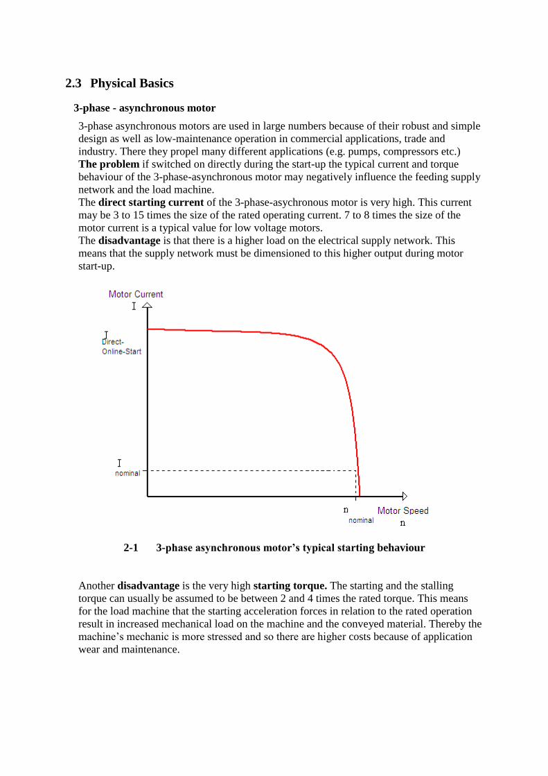
The direct starting current of the 3-phase-asychronous motor is very high. This current
may be 3 to 15 times the size of the rated operating current. 7 to 8 times the size of the
motor current is a typical value for low voltage motors.
The disadvantage is that there is a higher load on the electrical supply network. This
means that the supply network must be dimensioned to this higher output during motor
start-up.
2-1 3-phase asynchronous motor’s typical starting behaviour
Another disadvantage is the very high starting torque. The starting and the stalling
torque can usually be assumed to be between 2 and 4 times the rated torque. This means
for the load machine that the starting acceleration forces in relation to the rated operation
result in increased mechanical load on the machine and the conveyed material. Thereby the
machine’s mechanic is more stressed and so there are higher costs because of application
wear and maintenance.

2-2 3-phase asynchronous motor’s typical starting torque
Solution: Using the IGEL Electric soft starter the current and torque behaviour
can be optimally adapted to the requirement of the application.
Operating mode of the IGEL Electric soft starter
The soft starter has in each of the phases two antiparallel thyristors (except ISA-B2P and
ISA-A2P); one thyristor for the positive and one thyristor for the negative half wave.
Using phase angle control the r.m.s. value of the motor is fixed within a selectable voltage
ramp. The voltage will be increased from a definable start voltage using various control
methods to the motor rated voltage.
3-phase-asynchronous motor with soft start
The voltage applied to the motor acts proportional to the motor current. Thus the factor of
the voltage that is applied to the motor reduces the starting current.
In relation to the voltage applied to the motor the torque behaves quadratically. The start
torque is thus reduced quadratically based on the voltage applied to the motor
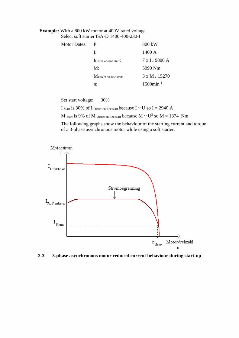
Example: With a 800 kW motor at 400V rated voltage.
Select soft starter ISA-D 1400-400-230-I
Motor Dates: P: 800 kW
I: 1400 A
IDirect on-line start: 7 x I e 9800 A
M: 5090 Nm
MDirect on-line start: 3 x M e 15270
n: 1500min-1
Set start voltage: 30%
I Start is 30% of I Direct on-line start because I ~ U so I = 2940 A
M Start is 9% of M Direct on-line start because M ~ U2 so M = 1374 Nm
The following graphs show the behaviour of the starting current and torque
of a 3-phase asynchronous motor while using a soft starter.
2-3 3-phase asynchronous motor reduced current behaviour during start-up
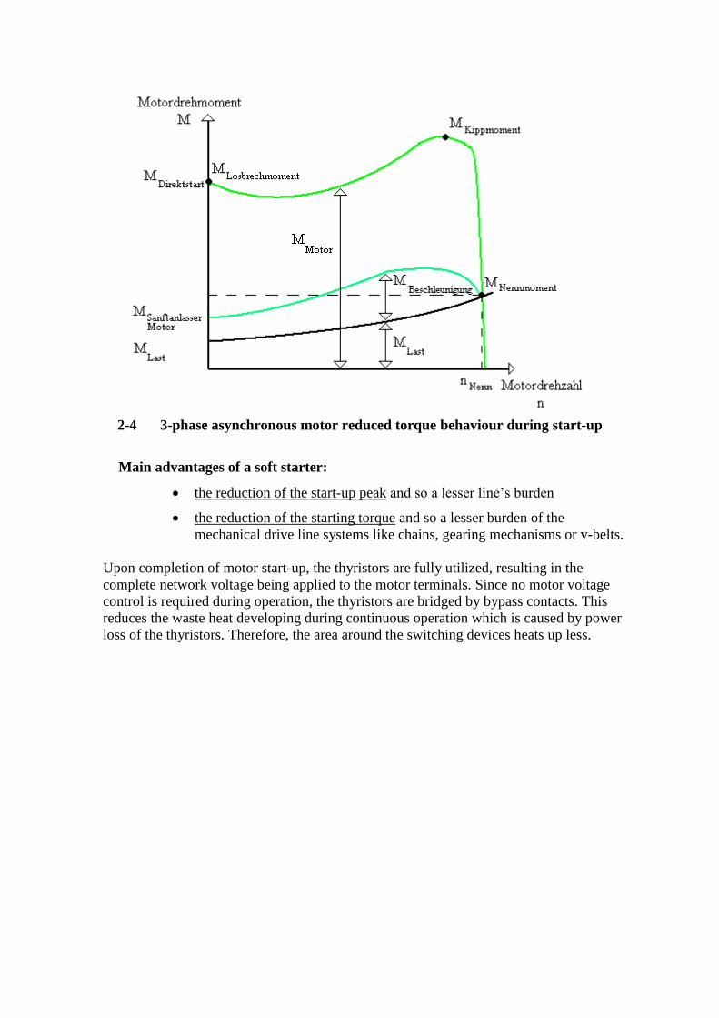
2-4 3-phase asynchronous motor reduced torque behaviour during start-up
Main advantages of a soft starter:
the reduction of the start-up peak and so a lesser line’s burden
the reduction of the starting torque and so a lesser burden of the
mechanical drive line systems like chains, gearing mechanisms or v-belts.
Upon completion of motor start-up, the thyristors are fully utilized, resulting in the
complete network voltage being applied to the motor terminals. Since no motor voltage
control is required during operation, the thyristors are bridged by bypass contacts. This
reduces the waste heat developing during continuous operation which is caused by power
loss of the thyristors. Therefore, the area around the switching devices heats up less.
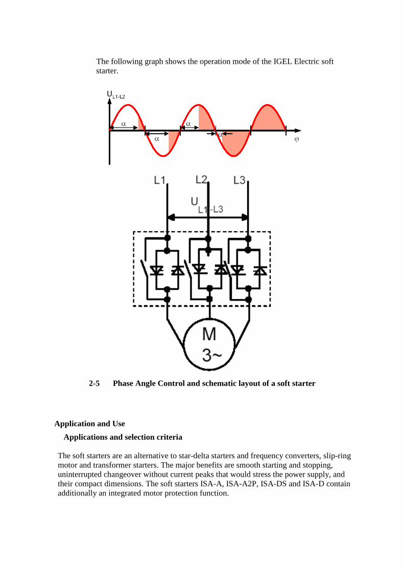
The following graph shows the operation mode of the IGEL Electric soft
starter.
2-5 Phase Angle Control and schematic layout of a soft starter
Application and Use
Applications and selection criteria
The soft starters are an alternative to star-delta starters and frequency converters, slip-ring
motor and transformer starters. The major benefits are smooth starting and stopping,
uninterrupted changeover without current peaks that would stress the power supply, and
their compact dimensions. The soft starters ISA-A, ISA-A2P, ISA-DS and ISA-D contain
additionally an integrated motor protection function.

Applications: Possible applications include:
o Pumps
o Compressors
o Conveyor belts
o Powerd Roller Conveyors
o Ventilators/Fans
o Hydraulic pumps
o Stirres
o Centrifugal Machines
o Milling Machines
o Mills
o Crushers
o Disk saws/ribbon saws
o shredders
o conveyor screws
o …
Advantages: Centrifugal pumps, reciprocating pumps
o Prevention of water hammering in pipe systems
o Prevention of valve setbacks
o Lower maintenance costs for installations
Conveyor belts, transport systems:
o because of lower acceleration/decceleration reduced stress on
transport belts
Stirrers, Mixers:
o Reduced starting current
Fans:
o Reduced stress on transmissions and V-belts
Ambient conditions for storage and operation
Permissiable ambient temperature for:
- Storage -25 °C to +70 °C
- Operation 0 °C to +40°C, from 40 °C with
derating
Permissable realtive air humidity: up to 95 % non condensing
Maximum permissable installation
height: 1000 m, from 1000m with derating
Caution:
Please ensure that no liquid, dust or conductive parts enter the soft starter!
2.4 Start Procedures / Methods with IGEL Electric Soft Starters
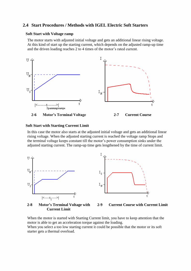
Soft Start with Voltage ramp
The motor starts with adjusted initial voltage and gets an additional linear rising voltage.
At this kind of start up the starting current, which depends on the adjusted ramp-up time
and the driven loading reaches 2 to 4 times of the motor’s rated current.
2-6 Motor’s Terminal Voltage 2-7 Current Course
Soft Start with Starting Current Limit
In this case the motor also starts at the adjusted initial voltage and gets an additional linear
rising voltage. When the adjusted starting current is reached the voltage ramp Stops and
the terminal voltage keeps constant till the motor’s power consumption sinks under the
adjusted starting current. The ramp-up time gets lengthened by the time of current limit.
2-8 Motor’s Terminal Voltage with
Current Limit
2-9 Current Course with Current Limit
When the motor is started with Starting Current limit, you have to keep attention that the
motor is able to get an acceleration torque against the loading.
When you select a too low starting current it could be possible that the motor or its soft
starter gets a thermal overload.

Soft Start with Pulse Start
If driving elements have a too high fricitonal or inertial torque there is a possibility of a
pulse-start. During the pulse start the terminal voltage gets limited to 80% of terminal
voltage in a time domain from 0.1 – 1 sec. After that the soft start begins with the adjusted
starting voltage and the adjusted ramp-up time.
2-10 Voltage Course Pulse-Start 2-11 Current Course Pulse-Start
Energy Saving
Some electronic motor soft starters contain the function energy saving. This function
improves the cosφ of the motor by controlling the terminal voltage of the motor by
continous phase angle in part-load- or idle-speed-range of the motor. In consideration of
the losses in the soft starter there is only a real energy saving in part-load-ranges possible
which are never under 60 % of the rated loading of the motor. During an alternation of
stress the motor’s terminal voltage gets immediately adjusted by the soft starter so as to
prevent a rev’s breaking in. Disadvantage of the energy saving function is a load of the
lines with harmonics by phase angle.
2-12 Voltage Course with Energy Saving 2-13 Current Course with Energy
Saving

Soft Stop
All soft starters of the series ISA contain the Soft Stop function. By courtesy of this
function you get a voltage-controlled run-out of the motor which prevents an abrupt
stopping of the motor above all in pump applications.
In all cases the function Soft Stop lengthens the motor’s natural run-out and works only
during load torque. By courtesy of lowering of the motor-terminal-voltage you get a field
weakening which after all implicates a rising motor current over the rated current.
2-14 Voltage Course Soft Stop 2-15 Current Course Soft Stop
Soft Stop for special pump curves
When liquid is pumped to a higher flat or to a duct system with higher pressures and the
pump get turned off, big kickbacks (water hammer) accrue. A normal soft starter’s run out
ramp can only reduce this phenomen inessentially because with a voltage reduction of
20 % the water column brings the pump to a standstill. The sepcial pump software enables
the pump run-down until the check valve closes softly and so it decreases the wear out of
the duct system.
End Switch
The load of the water column closes the valve before the voltage can get reduced to zero.
After that the pump rotates without load until the end of the adjusted run-out ramp. The
end switch enables the immediate motor stop after the valve was closed.
2-16 Soft Stop with pump curve

3 Technical Specifications
3.1 Introduction
Soft Start
The ISA-A soft starter incorporates 3 sets of thyristors to start a squirrel cage asynchronous
motor. By supplying a slowly increasing voltage, it provides a smooth and stepless
acceleration while drawing the minimum current to start the motor.
3-1 Soft-Start Characteristics
Soft Stop
A soft stop function can be enabled when „Ramp Down” potentionmeter is adjusted. Upon
opening the contact terminals A and B the stop signal is given. The starter’s load is slowly
reduced to zero.
3-2 Soft-Stop Characteristics
Note: The IGEL Electric soft starters ISA- A are designed to operate under normal
conditions. For frequent starts or starts at maximum ratings a larger sized starter should be
selected.
For long starts PTCs should be used in the motor windings. For the soft run-out as well as
pump-run out this is recommendable since it is only working during the run-out when
current load occurs.
Do not install any capacitive loads between motor and soft starter (e.g. compensation).
When soft starters are used do not incorporate any active filters.
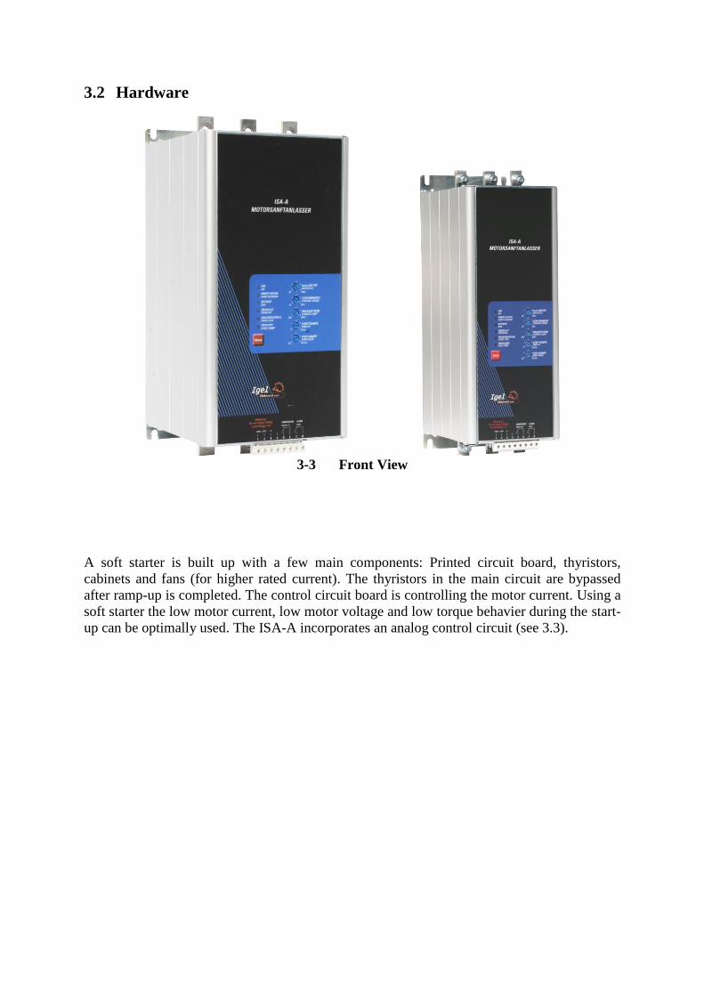
3.2 Hardware
3-3 Front View
A soft starter is built up with a few main components: Printed circuit board, thyristors,
cabinets and fans (for higher rated current). The thyristors in the main circuit are bypassed
after ramp-up is completed. The control circuit board is controlling the motor current. Using a
soft starter the low motor current, low motor voltage and low torque behavier during the start-
up can be optimally used. The ISA-A incorporates an analog control circuit (see 3.3).

3.3 Operating Board
3-4 Operating element
The ISA-A incorporates 5 internal potentiometers:
1. The „Motor Full Load Current“ adjusts the motor current at percentage. (Example: Set
ISA-A58 at 100 % = motor voltage 58 A)
2. The „Starting Torque“ determines the initial voltage to the motor. The torque is reducing
directly proportional to the square of the motor voltage. (Range: 10 to 50 % of the nominal
voltage)
3. The „Current Limit“ determines highest current during starting. (Range: 100 to 400%,
1 – 4 times Motor FLC)
4. The „Ramp Up“ determines the motor’s ramp-up time from initial to full voltage.
5. The „Ramp Down“ is used for a smooth motor stop against current load.
Note: Details in chapter 6 „Indications“
Anzeigen
Anzeige
Leuchten (LEDs)
ON – Green Will lit when all 3 phases are connected to the ISA-A.
RAMP UP / DOWN – Yellow Will lit upon start signal or during soft stop.
RUN – Green Will lit upon end of starting. The internal bypass contacts are
closed.
OVERLOAD – Red Electronic overload becomes operational upon end of starting
(see chapter 11 - motor protection)
PHASE LOSS – Red Will lit when one or two pahses are missing for more than 1 sec.
OVER TEMPERATURE - Red Will lit and trip the starter when the heatsink temperature >85 °C.
3-1 LED Indications

4 Starter Selection
4.1 Prior to installation
Make sure that fuses and circuit breakers of the main electric circuit are rated to operate under
direct start conditions and under the local short circuit conditions. Please order separately.
Select the circuit breaker (Trip selection) according to the harmonic content of the starting
current.
Detailed table, see Technical Specification.
4.2 Soft Starter Selection
1. Motor Current
Select the starter according to motor’s Full Laod Ampere (as indicated on its nameplate).
Ambient Temperature in
°C
Start
Current
Acceleration
Time
Starts per hour
40°C
300%
30 sec
4 starts per hour at
maximum ratings, at light
load applications the starts
can be increased (consult
factory)
400% In
5 sec
4-1 Operating Conditions
2. Line Voltage
Each starter is factory set for one of the following levels. (Please mention on the order.)
Voltage Tolerance
220 – 240 V 50/60Hz +10 – 15%
380 – 415 V 50/60Hz +10 – 15%
440 V 50/60Hz +10 – 15%
460 – 500 V 50/60Hz +10 – 15%
575 – 600 V 50/60Hz +10 – 15%
4-2 Line Voltage
5 Installation
5.1 Installation and Prior to Installation
The motor rated current has to be lower or according to the current of the soft starter while the
net voltage has to comply with the values on the nameplate. The soft starters comply with the
classes of protection IP20 and IP00. Please ensure that no liquid, dust or conductive parts
enter the soft starter.
Mounting
- The starter must be mounted vertically. Allow sufficient space above and below
the starter for suitable airflow.
- It is recommended to mount the starter directly on the rear metal plate of the
switchgear for better heat dissipation
- Do not mount the starter near heat sources.
- Protect the starter from dust and corrosive atmospheres.
Ambient Conditions
The starter is rated to operate at a temperature range of – 10oC to + 40oC. Relative non-
condensed humidity inside the housing should not exceed 95 %.
The heat dissipation during continuous operation is approx. 0.3 x In (in watts).
The heat dissipation during the start is for a maximum of 30 seconds approx. 3 times the start
current in watts. Please care for sufficient cooling in order to avoid an over temperature of the
starter. Over temperature can be reduced using additional fans.
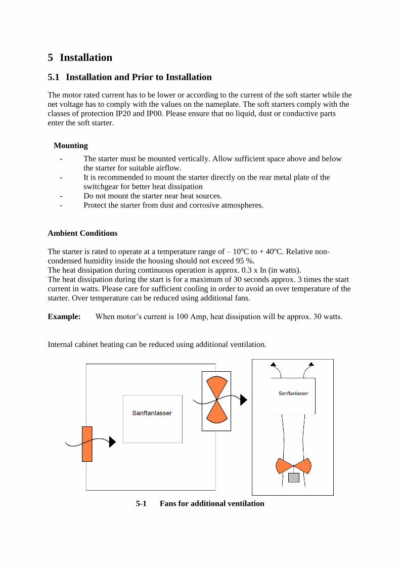
Example: When motor’s current is 100 Amp, heat dissipation will be approx. 30 watts.
Internal cabinet heating can be reduced using additional ventilation.
5-1 Fans for additional ventilation
Calculating the cabinet size, for non-ventilated metal cabinet:
Surface (m²) = 0.12 x total heat dissipation (in watts) / 60 – max. ambient temperature
* heat dissipation of all cabinet equipment
Note: When using a plastic cabinet a bypass contactor must be built in. The ISA-A series are
with already built-in bypass contactors.
Voltage Spike Protection
Voltage spikes may cause malfunction of the starter and damage the thyristors. When
expected, use suitable protection such as Metal Oxid Varistors (consult factory for further
details).
Short Circuit Protection
The ISA-A with thyristors should be protected against short circuit by semi-conductor fuses
with I²t-values. The recommended I²t-values see chapter 10 Technical Specifications.
Attention
Power factor correction capacitors must not be installed on starter’s
load side. When required, install capacitors on the line side, with 2 m
cable.
Warning
When lines voltage is connected to the starter, even if the start signal
has not been initiated, full voltage may appear on the output terminals
and on the starter’s load terminals. Therefore, for isolation purposes it is
required to connect a switch respectively a line contactor upstream to
the soft starter.
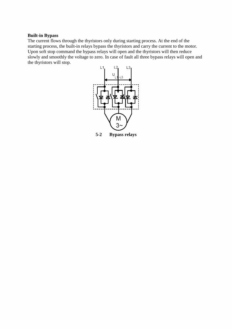
Built-in Bypass
The current flows through the thyristors only during starting process. At the end of the
starting process, the built-in relays bypass the thyristors and carry the current to the motor.
Upon soft stop command the bypass relays will open and the thyristors will then reduce
slowly and smoothly the voltage to zero. In case of fault all three bypass relays will open and
the thyristors will stop.
5-2 Bypass relays

5.2 Load
5-3 Circuit Schematic
The soft starter incorporates two main voltage contacts (depending on the size of the soft
starter).
- Busbar connections (IP00)
- Screw terminals (IP20)
The terminals L1/L2/L3 will be connected to the mains. Important: The short circuit
protection should be installed in the mains. The motor protection is taken over by the soft
starter. The terminals U/V/W are connecting the motor.
1) For the short circuit protection use fuses or circuit breakers.
2) For an emergency stop a main contactor must be installed.
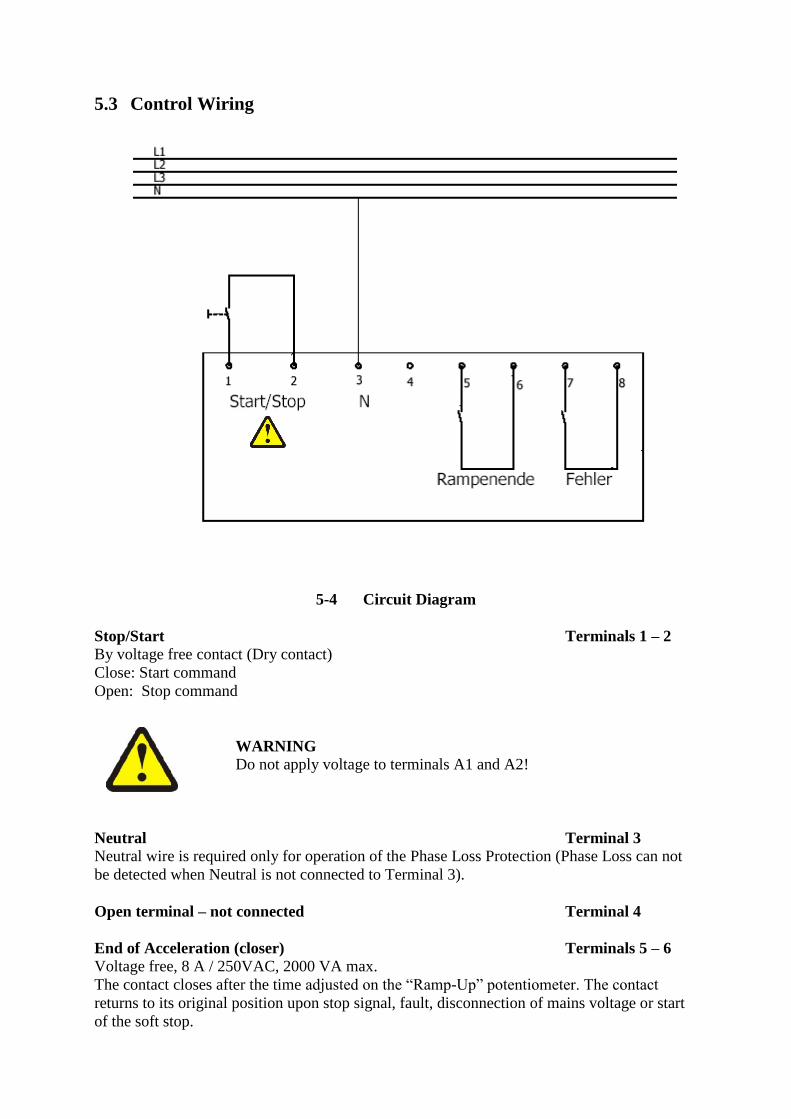
5.3 Control Wiring
5-4 Circuit Diagram
Stop/Start Terminals 1 – 2
By voltage free contact (Dry contact)
Close: Start command
Open: Stop command
WARNING
Do not apply voltage to terminals A1 and A2!
Neutral Terminal 3
Neutral wire is required only for operation of the Phase Loss Protection (Phase Loss can not
be detected when Neutral is not connected to Terminal 3).
Open terminal – not connected Terminal 4
End of Acceleration (closer) Terminals 5 – 6
Voltage free, 8 A / 250VAC, 2000 VA max.
The contact closes after the time adjusted on the “Ramp-Up” potentiometer. The contact
returns to its original position upon stop signal, fault, disconnection of mains voltage or start
of the soft stop.
Use of the “End of Accelaration” Contact
This contact can be used for:
- Activating a valve after a compressor has reached full speed.
- Release for loading a conveyor belt after the motor has reached full speed.
Fault Contact (Schliesser – Closing terminal) Terminals 7 - 8
Voltage free, 8 A/250VAC, 2000VA max.
The contact closes upon operation of any fault. The contact opens after the fault has been
removed upon reset, or upon disconnection of mains voltage.
Warning
Do not use the fault contact to trip an upstream contactor. When the
fault contact trips the upstream contactor, mains voltage will be
disconnected, thus resetting the starter and the motor will be restart
instantaneously upon voltage recoverage.
Attention
Start/Stop with a maintained contact!
When the line contactor is operated by a maintained contact in case of
lines failure, the motor will be automatically restarted upon voltage
recoverage. When resetting after a fault with the “Reset” button, the
motor will restart immediately. It is therefore recommended not to
connect the fault relay to the line contactor.
5 Starter Settings
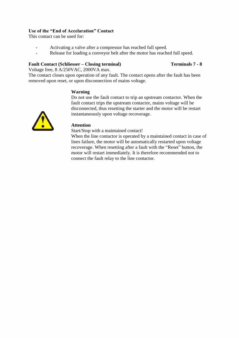
Full Load Current (Motor FLC)
The starter settings allow an exact adjustment of the ISA-A to the connected motor.
Set FLC potentiometer according to the following formula:
Motor FLC % = Motor FLA : starter FLC x 100
Example:
When starting a 27A motor using ISA-A 31:
FLC% = 27/31 x 100 = 87 %
5-1 Potentiometer
Therefore set the FLC% to a reading of 87%.
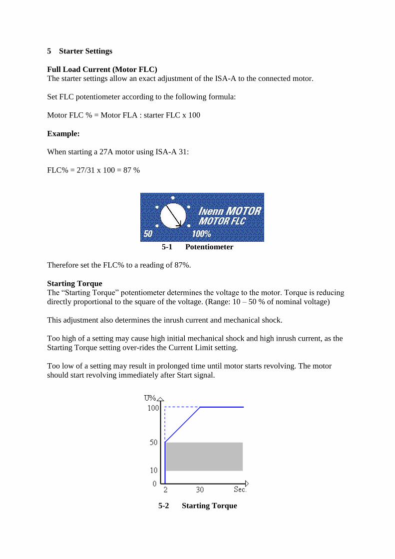
Starting Torque
The “Starting Torque” potentiometer determines the voltage to the motor. Torque is reducing
directly proportional to the square of the voltage. (Range: 10 – 50 % of nominal voltage)
This adjustment also determines the inrush current and mechanical shock.
Too high of a setting may cause high initial mechanical shock and high inrush current, as the
Starting Torque setting over-rides the Current Limit setting.
Too low of a setting may result in prolonged time until motor starts revolving. The motor
should start revolving immediately after Start signal.
5-2 Starting Torque
Current Limit
Determines motor’s highest current during starting. Range is 100 – 400 % of motor FLC.
A high of a setting will allow high currents to be drawn from mains, resulting in fast
acceleration.
Too low of a setting may prevent the motor from completion the acceleration process and
reaching full speed within the maximum starting phase. The starting phase will be stopped
because of overload.
Generally, this setting should be adjusted to the highest acceptable value while the ramp-up
time still may influence the soft start.
5-3 Current Limit
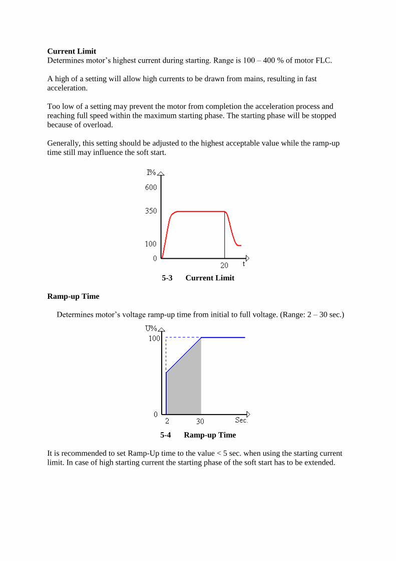
Ramp-up Time
Determines motor’s voltage ramp-up time from initial to full voltage. (Range: 2 – 30 sec.)
5-4 Ramp-up Time
It is recommended to set Ramp-Up time to the value < 5 sec. when using the starting current
limit. In case of high starting current the starting phase of the soft start has to be extended.
Note:
1. Setting current limit low it will extent the start.
2. When motor reaches full speed before voltage reaches nominal, ramp-up
time adjustment is overridden, causing voltage to quickly ramp up to
nominal
Attention
The starting current should not exceed the allowable conditions as shown in
chapter 4 – Starter Selection.
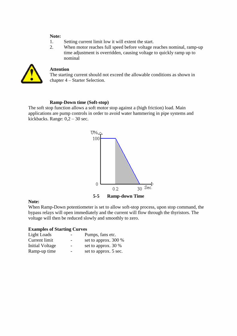
Ramp-Down time (Soft-stop)
The soft stop function allows a soft motor stop against a (high friction) load. Main
applications are pump controls in order to avoid water hammering in pipe systems and
kickbacks. Range: 0,2 – 30 sec.
5-5 Ramp-down Time
Note:
When Ramp-Down potentiometer is set to allow soft-stop process, upon stop command, the
bypass relays will open immediately and the current will flow through the thyristors. The
voltage will then be reduced slowly and smoothly to zero.
Examples of Starting Curves
Light Loads - Pumps, fans etc.
Current limit - set to approx. 300 %
Initial Voltage - set to approx. 30 %
Ramp-up time - set to approx. 5 sec.

5-6 Examples of Starting Curves 1
Upon start the voltage quickly increases to the Initial Voltage value of 30 % U and than
gradually ramps up to nominal.
The current will simultaneously increase to peak current value, which can be current limit
setting or less, before smoothly decreasing to the operation current.
The motor will accelerate to full speed smoothly.
High loads - Conveyor belts, Crushers etc.
Current limit - set to approx. 350 %
Initial Voltage - set to 50 %
Ramp-Up time - set to 5 sec.
5-7 Examples of Starting Curves 2
Upon start the voltage quickly increases to a value of 50 % U and than the voltage and current
increase simultaneously until current reaches current limit value.
The voltage remains at this value until motor reaches nominal speed.
When current starts to decrease the voltage ramp will be free again so that voltage continues
to ramp-up to nominal. At this time the motor should have smoothly accelerated to full speed.
6 Start-up Procedure
1. Set Motor Full Load Current according to the following calculation:
Motor FLC % = Motor FLC / Starter FLC x 100
2. Set other potentiometers according to the application (see examples)
3. Connect mains voltage, the motor and the control to the starter.
4. Start the motor (contact to terminals 1 – 2), if it begins revolving shortly after start
signal proceed to 5. If not, increase Initial Voltage setting until motor starts to turn
shortly after start signal.
When mechanical shock and initial inrush current are too high, decrease current limit
setting and proceed to 6.
5. If motor begins to turn shortly after start signal and smoothly accelerates to nominal
proceed to 6. If current during acceleration is too high, slightly decrease current limit
setting. If motor not accelerates to nominal as required increase the current limit.
6. Stop order (open Terminals 1 and 2), wait until the motor stops.
7. Slightly increase both potentiometers (Initial Voltage and Current Limit) adjustments
to allow for load variations.
8. Start the motor again and verify that acceleration process to full speed is as required.
9. If acceleration time is too short, increase Ramp-Up time setting.
When soft stop is required set Ramp-Down Potentiometer to the required time (minimum
deceleration time is recommended). After setting all parameters check that process is as
required.
Attention
If Ramp-Down potentiometer is not in the minimum setting the adjusted
ramp-down time determines the motor. An advance stop may only be
performed by disconnecting the mains voltage. Emergency stop or emergency
switch off must be effected through advance installed contact element. The soft
starter itself has no emergency stop function.
7 Motor Protection
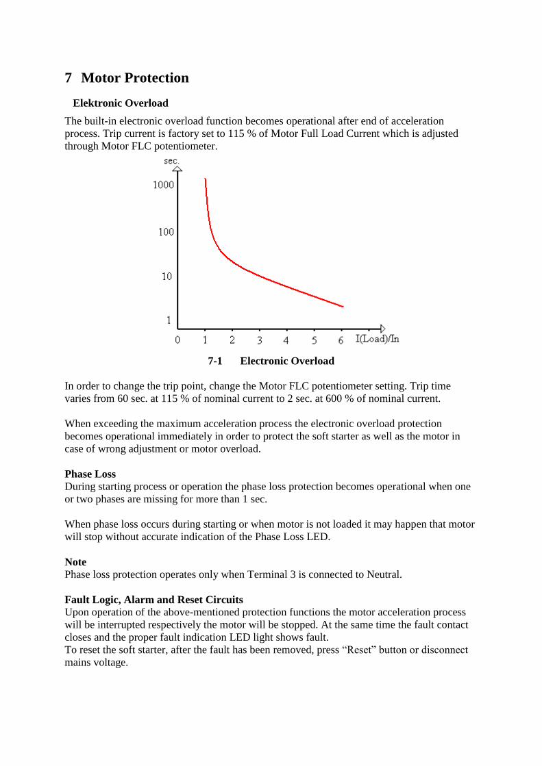
Elektronic Overload
The built-in electronic overload function becomes operational after end of acceleration
process. Trip current is factory set to 115 % of Motor Full Load Current which is adjusted
through Motor FLC potentiometer.
7-1 Electronic Overload
In order to change the trip point, change the Motor FLC potentiometer setting. Trip time
varies from 60 sec. at 115 % of nominal current to 2 sec. at 600 % of nominal current.
When exceeding the maximum acceleration process the electronic overload protection
becomes operational immediately in order to protect the soft starter as well as the motor in
case of wrong adjustment or motor overload.
Phase Loss
During starting process or operation the phase loss protection becomes operational when one
or two phases are missing for more than 1 sec.
When phase loss occurs during starting or when motor is not loaded it may happen that motor
will stop without accurate indication of the Phase Loss LED.
Note
Phase loss protection operates only when Terminal 3 is connected to Neutral.
Fault Logic, Alarm and Reset Circuits
Upon operation of the above-mentioned protection functions the motor acceleration process
will be interrupted respectively the motor will be stopped. At the same time the fault contact
closes and the proper fault indication LED light shows fault.
To reset the soft starter, after the fault has been removed, press “Reset” button or disconnect
mains voltage.
Over Temperature Protection
The over temperature protection function is installed to protect the soft starter. A thermal
sensor mounted on the heatsink switches off when its heatsink temperature rises above 85°C.
Warning
This over temperature protection is designed to operate under normal
conditions and will operate in case the following faults occur:
Incorrect starter selection
Too frequent starting at max. conditions
Repeated starting under fault conditions
Extended overload
Insufficient ventilation
Other abnormal conditions
In case of frequent starting the internal thyristors may overheat before
the heatsink reaches its over-temperature protection of 85 °C.
Attention
When soft starter is operated by a maintained contact and start
command still is adjusted, resetting the fault will start the motor
immediately.
Warning
Do not use the fault contact to trip an upstream contactor.
In case Start/Stop input is not changed thus resetting the ISA-A as well
as the upstream contactor and the motor will restart instantaneously.

8 Frequently Asked Questions
Main contactor
Question: Is there any requirement to put a main contactor in series before the soft
starter?
Answer: The soft starter does not require any main contactor but we recommend the use
of one for emergency stop and/or trip the overload relay. In some applications a
moulded case circuit breaker (MCCB) can be used instead of the main
contactor.
Ambient Temperature
Question: Can I use a soft starter if the ambient temperature is higher than the
recommended value during operation?
Answer: The soft starter can normally be operated at higher ambient temperature during
operation if the rated current for the unit is derated according to the
manufacturer’s recommendation.
Thyristor shorted
Question: Is it possible to run a softstarter with one thyristor shorted?
Answer: Yes, it is possible but not for all types of thyristors.
Soft stop applications
Question: What applications are suitable for soft stop?
Answer: Pumps and conveyor belts loaded with fragile products are the two main
applications suitable for soft stop.
Advantages of by-pass
Question: What are the advantages of using by-pass?
Answer: Reduction of power loss.
Power loss
Question: What is the power loss of a soft starter during a continuous run?
Answer: The values can normally be found in the catalogue. For IGEL Electric soft
starter the following formula can be used:
3 x starting current for max. 30 sec. (without by-pass)
Utilisation category
Question: What utilisation category should be used for the main contactor?
Answer: Main contactor: always use AC-3
Fault indication when starting
Question: Why does the soft starter indicate a fault when the start signal is given to the
main contactor and soft starter at the same time?
Answer: If main contactor is closed too late the soft starter will indicate this as a phase
loss fault. Delay the start signal to the soft starter by approx. 5 sec. to solve this
problem.
Test without motor
Question: Can I test a soft starter without using a motor?
Answer: No, this is not possible since there will be no current going through the soft
starter and some types will also indicate that no motor is connected.
Overload relay trips during starting
Question: Why does the overload relay trip during start?
Answer: Possible reasons can be one of these:
too low current limit
too long ramp time
too low initial voltage
wrong tripping class on the overload protection
wrong setting on the overload protection
Separate overload relay when using by-pass
Question: Do I need a separate overload relay when using a soft starter with built-in
electronic overload and by-pass?
Answer: If the current transformer of the soft starter can be installed so that the
measuring can be performed when by-passed a separate relay is not required.
Also when by-passed the protection functions of IGEL Electric
soft starters are always in setted.
Different frequency
Question: Can I use the same soft starter for both 50 and 60 Hz?
Answer: It is possible with all type of IGEL Electric soft starters as long as the curve is
sinusoidal.

Voltage fluctuations
Question: What voltage fluctuations are allowed for the soft starters?
Answer: The minimum and maximum value where we can guarantee full function is
– 15% to + 10 % of the rated value. This is also stated in the IEC-standard.
Example: 400 V – 15 % to + 10 %. Range: 340 V – 440 V.
Semi-conductor fuses
Question: Do I always have to use semi-conductor fuses?
Answer: When using semi-conductor fuses a type 2 co-ordination can be achieved. It is
possible to use a moulded case circuit breaker (MCCB) or fuses instead but
then with a type 1 co-ordination.
Use at high altitudes
Question: Can I use the soft starter at high altitudes and what do I have to consider?
Answer: It is possible. When using soft starters at high altitudes the rated current
for the unit has to be derated due to less cooling. In some cases a larger soft
starter is required to be able to cope with the motor current when used at high
altitudes. For questions, please consult factory.

9 Technical Specifications
Environment
Supply Voltage
Three Phases, phase to
phase
380 – 415Vac+10% - 15%
460 – 500Vac+10% -15%
575 – 600Vac+10% - 15%
Frequency 50 / 60 Hz
Load
Three-Phase–
asynchronous motor in
star- or delta connection
Degree of protection cabinet A1-IP 20
cabinet A2/A3/A4 – IP 00
Altitude 1000 m above sea level In case of different altitudes
please consult Igel.
Adjustments
Motor FLC 50 – 100%
Starting Torque (Initial
Voltage)
10 – 50% of nominal
voltage
Current Limit 100% - 400% of nominal
current
Ramp-Up Time (Soft
Start)
2 – 30 sec
Ramp-Down Time (Soft
Stop)
0.2 – 30 sec
Protection
Electronic Overload I²t, factory set at 115% overload, active only during run.
Phase Loss Trips when one phase is missing (only when Neutral is
connected)
Over Temperature Trips when heatsink temperature of the soft starter >85 °C
Reset Button To reset the starter, after the fault has been removed.
Temperatures
Operation -10 – 40°C
Storage -20 – 70 °C
Relative Humidity 95 % non condensed
9-1 Technical Specifications
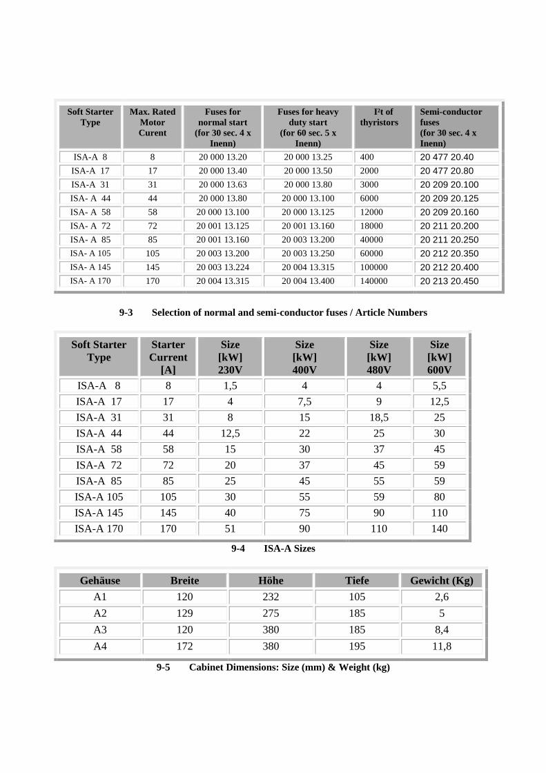
Soft Starter
Type
Max. Rated
Motor
Curent
Fuses for
normal start
(for 30 sec. 4 x
Inenn)
Fuses for heavy
duty start
(for 60 sec. 5 x
Inenn)
I²t of
thyristors
Semi-conductor
fuses
(for 30 sec. 4 x
Inenn)
ISA-A 8 8 20 000 13.20 20 000 13.25 400 20 477 20.40
ISA-A 17 17 20 000 13.40 20 000 13.50 2000 20 477 20.80
ISA-A 31 31 20 000 13.63 20 000 13.80 3000 20 209 20.100
ISA- A 44 44 20 000 13.80 20 000 13.100 6000 20 209 20.125
ISA- A 58 58 20 000 13.100 20 000 13.125 12000 20 209 20.160
ISA- A 72 72 20 001 13.125 20 001 13.160 18000 20 211 20.200
ISA- A 85 85 20 001 13.160 20 003 13.200 40000 20 211 20.250
ISA- A 105 105 20 003 13.200 20 003 13.250 60000 20 212 20.350
ISA- A 145 145 20 003 13.224 20 004 13.315 100000 20 212 20.400
ISA- A 170 170 20 004 13.315 20 004 13.400 140000 20 213 20.450
9-3 Selection of normal and semi-conductor fuses / Article Numbers
Soft Starter
Type
Starter
Current
[A]
Size
[kW]
230V
Size
[kW]
400V
Size
[kW]
480V
Size
[kW]
600V
ISA-A 8 8 1,5 4 4 5,5
ISA-A 17 17 4 7,5 9 12,5
ISA-A 31 31 8 15 18,5 25
ISA-A 44 44 12,5 22 25 30
ISA-A 58 58 15 30 37 45
ISA-A 72 72 20 37 45 59
ISA-A 85 85 25 45 55 59
ISA-A 105 105 30 55 59 80
ISA-A 145 145 40 75 90 110
ISA-A 170 170 51 90 110 140
9-4 ISA-A Sizes
Gehäuse Breite Höhe Tiefe Gewicht (Kg)
A1 120 232 105 2,6
A2 129 275 185 5
A3 120 380 185 8,4
A4 172 380 195 11,8
9-5 Cabinet Dimensions: Size (mm) & Weight (kg)
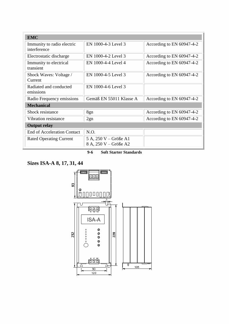
EMC
Immunity to radio electric
interference
EN 1000-4-3 Level 3 According to EN 60947-4-2
Electrostatic discharge EN 1000-4-2 Level 3 According to EN 60947-4-2
Immunity to electrical
transient
EN 1000-4-4 Level 4 According to EN 60947-4-2
Shock Waves: Voltage /
Current
EN 1000-4-5 Level 3 According to EN 60947-4-2
Radiated and conducted
emissions
EN 1000-4-6 Level 3
Radio Frequency emissions Gemäß EN 55011 Klasse A According to EN 60947-4-2
Mechanical
Shock resistance 8gn According to EN 60947-4-2
Vibration resistance 2gn According to EN 60947-4-2
Output relay
End of Acceleration Contact N.O.
Rated Operating Current 5 A, 250 V – Größe A1
8 A, 250 V – Größe A2
9-6 Soft Starter Standards
Sizes ISA-A 8, 17, 31, 44
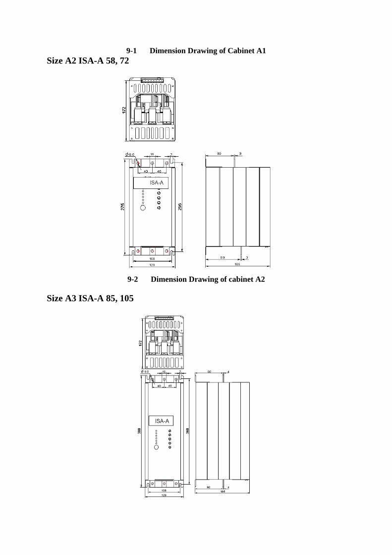
9-1 Dimension Drawing of Cabinet A1
Size A2 ISA-A 58, 72
9-2 Dimension Drawing of cabinet A2
Size A3 ISA-A 85, 105
9-3 Dimension Drawing of cabinet A3
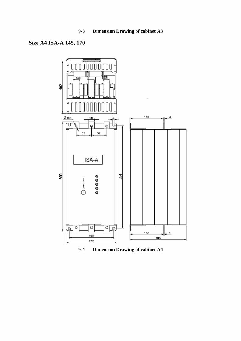
Size A4 ISA-A 145, 170
9-4 Dimension Drawing of cabinet A4

10 Odering Information
Example: ISA- A
85 -480 -8 -I
ISA- A -xxxx -xxxx -xxx -xxx
Starter Rated Current (1)
Line Voltage Motor (2)
Options (3)
Design (4)
(1) Starter Current 8, 17, 31, 44,58,72,85,105,145, 170
(2) Line Voltage to specify
400 380-440 VAC + 10%-15%
480 460-500 VAC + 10%-15%
600 575-600 VAC + 10%-15%
(3) Options to specify
0 no options
8 Design for rough environment
(4) Design to specify
I Standard

IGEL® Electric GmbH IGEL® Electric Dubai
Industrieweg 13-15 Dubai Creek Tower, Office No
22-B
D-48324 Sendenhorst U.A.E. Dubai
Fon +49 2526-9389-0 Fon: +971 429456-05
Fax +49 2526-9389-22 Fax: +971 294561-0
www.igelelectric.de
Copyright IGEL Electric GmbH.
All rights reserved.
Weitergabe sowie Vervielfältigung dieser unterlage, Verwertung und Mitteilung ihres Inhalts ist nicht
gestattet, soweit nicht ausdrücklich zugestanden. Zuwiderhandlungen verpflichten zu Schadenersatz. Alle
Rechte vorbehalten, insbesondere für den Fall der Patenterteilung oder GM-Eintragung.
Haftungsausschluss
Wir haben den Inhalt der Druckschrift auf Übereinstimmung mit der beschriebenen Hard- und Software
geprüft. Dennoch können Abweichungen nicht ausgeschlossen werde, so dass wir für die vollständige
Übereinstimmung keine Gewähr übernehmen. Die Angaben in dieser Druckschrift werden regelmäßig
überprüft, notwendige Korrekturen sind in den nachfolgenden Auflagen enthalten.