Embed Size (px)
Citation preview

Disclosure to Promote the Right To Information
Whereas the Parliament of India has set out to provide a practical regime of right to information for citizens to secure access to information under the control of public authorities, in order to promote transparency and accountability in the working of every public authority, and whereas the attached publication of the Bureau of Indian Standards is of particular interest to the public, particularly disadvantaged communities and those engaged in the pursuit of education and knowledge, the attached public safety standard is made available to promote the timely dissemination of this information in an accurate manner to the public.
इंटरनेट मानक
“!ान $ एक न' भारत का +नम-ण”Satyanarayan Gangaram Pitroda
“Invent a New India Using Knowledge”
“प0रा1 को छोड न' 5 तरफ”Jawaharlal Nehru
“Step Out From the Old to the New”
“जान1 का अ+धकार, जी1 का अ+धकार”Mazdoor Kisan Shakti Sangathan
“The Right to Information, The Right to Live”
“!ान एक ऐसा खजाना > जो कभी च0राया नहB जा सकता है”Bhartṛhari—Nītiśatakam
“Knowledge is such a treasure which cannot be stolen”
“Invent a New India Using Knowledge”
है”ह”ह
IS 9002-5 (1979): Equipment for Environmental Tests forElectronic and Electrical Items, Part 5: Equipment forVibration (Sinusoidal) Test [LITD 1: Environmental TestingProcedure]


IS : 9002 ( Part V ) - 1979
Indian Standard
SPECIFICATION FOR EQUIPMENT FOR ENVIRONMENTAL
TESTS FOR ELECTRONIC AND ELECTRICAL ITEMS
PART V EQUIPMENT FOR VIBRATION ( SINUSOIDAL ) TEST
Environmental Testing Procedures Sectional Committee, LTDC 2
Chairman Representing
MAJ-GEN D. SWAROOP Ministry of Defence ( R & D )
Members BRIG N. DAYAL Ministry of Defence ( DGI )
LT-COL V. K. KHANNA ( Alternate ) DIRECTOR STANDARDS ( S & T ) Research, Designs & Standards Organization
( Ministry of Railways ), Lucknow JOINT DIRECTOR STANDARDS
( S & T )-I ( Alternate ) JOINT DIRECTOR -STANDARDS
( E-III ) ( Alternate ) GENERAL SECRETARY SHR~ GHAS~TA SINGH
Society of Environmental Engineers, Bangalore Central Electronics Engineering Research Institute
( CSIR ), Pilani SHRI B. P. GHOSH SHRI J. G. JAIN
National Test House, Calcutta Radio Electronic & Television Manufacturers’
Association, Bombay CENTRAL STANDARDIZATION OFFICER ( Afternare )
SHRI JOFN FRANCIS Posts and Telegraphs Board, New Delhi Philips India Limited, Bombay SHRI S. P. KULKARNI
DR P. K. DUTTA ( Alternate ) SHRI V. A. MURARI Lucas-TVS Ltd, Madras
SHRI C. RANGANATHAN ( Alternate ) BRIG Y. NIRULA Instrumentation Ltd, Kota SHRI D. V. PETKAR Bhabha Atomic Research Centre, Trombay, Bombay SHRI P. S. K. PRASAD Bharat Electronics Ltd, Bangalore
SHRI D. S. GOPALAKRISHNA ( Alternate )
( Continued on page 2 )
0 Copyright 1980
INDIAN STANDARDS INSTITUTION
This publication is protected under the Indian Copyright Act ( XIV of 1957 ) and reproduction in whole or in part by any means except with written permission of the publisher shall be deemed to be an infringement of copyright under the said Act.

IS : 9002 ( Part V ) - 1979
( Continued from page 1 )
Members Representing SHRI C. V. RAGHURAMAN National Radio & Electronics Co Ltd, Bombay SHRI P. V. RAO Indian Telephone Endustries Ltd, Bangalore
SHRI A. SATYANARAYANA ( Alternate ) SHRI P. SANDELL All India Instrument Manufacturers’ & Dealers’
Association, Bombay SHRI H. C. VERMA ( Alternate )
SHRI T. V. A. SUBRAMANIAN Electronics Corporation of India Ltd, Hyderabad SHRI G. C. SAXENA ( Alternate )
SHRI K. N. TIWARI -Ministry of Defence ( LCSO ) SHRI P. K. SHUKLA ( Alternate )
DR R. C. TRIPATHI Department of Electronics, New Delhi SHRI M. VAIDYANATHAN Directorate General of Observatories, New Delhi DR R. P. WADHWA National Physical Laboratory (CSIR ), New Delhi
SHR~ P. SURYANARAYANA ( Alternate ) SHRI R. C. JAIN, Director General, IS1 ( Ex-officio Member )
Head ( Electronics )
Secretory SHRI HARCHARAN SINGH
Deputy Director ( Electronics ), IS1
Panel for Equipment for Environmental Tests, LTDC 2 : P6
Convener
SHRI G. R. GHOSH Ministry of Defence ( DGI )
Members SHRI B. RAGHAVENDRA RAO ( Alternate to
Shri G. R. Ghosh ) SHRI D. S. GOPALAKRISHNA Bharat Electronics Ltd, Bangalore SHRI S. P. KULKARNI Philips India Ltd, Bombay
DR P. K. DUTTA ( Alternate ) SHRI N. RAM PRASAD Vijayalakshmi Industries, Bangalore
SHRI MOSES XAVIAR ( Alternate ) SHRI C. RANGANATHAN REPRESENTATIVE
Lucas-TVS Ltd, Madras Electronics Corporation of India Ltd, Hyderabad
SHRI D. SUBRAMANYAN Indian Telephone Industries Ltd, Bangalore SHRI A. SATYANARAYANA ( Alternate )
SHRI P. SURYANARAYANA National Physical Laboratory ( CSIR ), New Delhi SHRI K. N. TIWARI Ministry of Defence ( LCSO )
SHRI P. K. SHUKLA ( Alternate ) SHRI B. G. UDAYA KUMAR Kashinath & Co, Hyderabad
SHRI B. RAMA RAO ( Alternate )
2

IS : 9002 ( Part V ) - 1979
Indian Standard
SPECIFICATION FOR
EQUIPMENT FOR ENVIRONMENTAL TESTS FOR ELECTRONIC AND
ELECTRICAL ITEMS
PART V EQUIPMENT FOR VIBRATION ( SINUSOIDAL ) TEST
0. FOREWORD
0.1 This Indian Standard ( Part V) was adopted by the Indian Standards Institution on 12 June 1979, after the draft finalized by the Environmental Testing Procedures Sectional Committee had been approved by the Electronics and Telecommunication Division Council.
0.2 The object of this standard ( Part V) is primarily to guide the environmental equipment manufacturers with respect to broad specifications for their equipment and to assist the users of such equipment to properly define the requirements in the indent for the equipment. The requirements of the equipment largely depend on the conditions of environmental tests to be simulated or created. It is expected that this standard will harmonize the various requirements of the equipment.
0.3 Certain requirements have been specified in a general form in view of practical difficulties in defining such requirements quantitatively. It is presumed that with the experience gained, more precise requirements will be laid down far such equipment.
0.4 An overall performance assessment -of the complete equipment for a short duration has been included although it may be realized that it may not be entirely sufficient. This will at least ensure the functional perform- ance and operatability of the equipment. Many of the constructional requirements specified can be checked through visual examination.
0.5 In view of the subjective nature of some of the requirements, sufficient care shall be taken in using this standard.
0.6 This standard is one of a series of Indian Standards on equipment for
3
IS : 9002 ( Part V ) - 1979
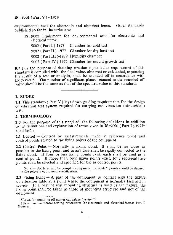
environmental tests for electronic and electrical items. Other standards published so far in the series are:
IS : 9002 Equipment for environmental tests for electronic and electrical items:
9002 ( Part I )-1977 Chamber fdr cold test
9002 ( Part II )-1977 Chamber for dry heat test
9002 ( Part III )-1979 Humidity chamber
9002 ( Part IV )-1979 Chamber for mould growth test
0.7 For the purpose of deciding whether a particular requirement of this standard is complied with, the final value, observed or calculated, expressing the result of a test or analysis, shall be rounded off in accordance with IS : 2-1960*. The number of significant places retained in the rounded off value should be the same as that of the specified value in this standard.
1. SCOPE
1.1 This standard ( Part V ) lays down guiding requirements for the design of vibration test system required for carrying out vibration ( sinusoidal ) test.
2. TERMINOLOGY
2.0 For the purpose of this standard, the following definitions in addition to the definitions and explanation of terms given in IS : 9000 ( Part I )-19777 shall apply.
2.1 Control - Control by measurements made at reference point and control points related to the fixing points of the equipment.
2.2 Control Point-Normally a fixing point. It shall be as close as possible to the fixing point and in any case shall be rigidly connected to the fixing point. If four or less fixing points exist, each shall be used as a control point. If more than four fixing points exist, four representative points shall be selected and specified for use as control points.
NOTE - For large and/or complex equipment, the control points should be defined in the relevant equipment specification.
2.3 Fixing Point - A part of the equipment in contact with the fixture or vibration table at a point where the equipment is normally fastened in service. If a part of real mounting structure is used as the fixture, the fixing point shall be taken as those of mounting structure and snot of the equipment.
*Rules for rounding off numerical values ( revised ). tBasic environmental testing procedures for electronic and electrical items: Part I
General.
4

IS : 9002 ( Part V ) - 1979
2.4 Reference Point -The single point from which the reference signal is obtained to confirm the test requirement and is taken to represent the motion of the equipment. It may be a control point, or a fictitious point created by a manual or automatic processing of the signals from the control points. Unless otherwise specified, the signal from the reference point shall be the average of signals from the control points. The relevant equipment specification shall state the point to be used or how it should be chosen. It is recommended that for large and/or complex equipment a fictitious point be used.
2.5 Vibration Amplitude - The amplitude specified in terms of constant displacement or constant velocity or constant acceleration. The term ‘amplitude’ is used in the wider sense of peak value of an oscillating quantity. Each value of displacement amplitude is associated with corres- ponding value of velocity or acceleration amplitude, the relationship is as follows:
4 72 f” Acceleration (m/s”) - 1 ooo . - --~ - displacement (mm)
Velocity ( m/s ) 2Tf = m. displacement (mm)
where f is frequency in Hz.
NOTE - For any combination of displacement and acceleration amplitude or displacement and velocity amplitude, a crossover frequency can be calculated from the above relationship, so that the magnitude of vibration is same at this frequency. Hence, a frequency range may be swept continuously, changing from constant dis- placement to constant acceleration ( for constant velocity ) and vice versa at rhe crossover frequency.
3. CHARACTERISTICS
3.1 General - The required characteristics of the vibration generator and fixture when loaded for the conditioning processes shall be as follows.
3.2 Basic Motion - The basic motion shall be sinusoidal and such that the fixing points of the item are moving substantially in phase and in straight parallel lines except as in 3.3.
3.3 Transverse Motion - The maximum vibration amplitude at the fixing points in any direction perpendicular to the intended direction ( including that due to rocking, torsional vibration, etc ) shall not exceed 25 percent of the specified amplitude.
NOTE - In some cases, for example, for large items, it may be difficult to maintain a limit of 25 percent. In such cases, the value shall be noted and agreed between the customer and the supplier.
5

IS : 9002 ( Part V ) - 1979
3.4 Distortion - The total rms harmonic content of the acceleration corres- ponding to the specified amplitude at the driving frequency shall not exceed 25 percent, unless compensated for by increasing the driving amplitude so as to restore the amplitude at the fundamental frequency to the specified value. In such cases, the distortion value shall be noted and stated in the test report.
The distortion measurement shall cover the frequency up to 5 000 HZ or five times the driving frequency, whichever be the greater.
3.5 Vibration Amplitude Tolerances - The actual vibration amplitude in the required direction shall be equal to the specified value within the following tolerances:
a) At the reference point ( which may be specified by the relevant specification ):
1) In the frequency range where displacement amplitude is specified
f 15 percent
2) In the frequency range where acceleration * 10 percent amplitude is specified
b) At each specified control point:
Frequency In the Frequency Range In the Frequency Range where Displacement whem Accederation
Amplitude is Specified Amplitude is Specified
Up to 150 Hz i 25 percent f 15 percent
Above 150 Hz - f25 percent
NOTE 1 - In some cases, for example, for large items and/or at high frequencies, it may be difficult to achieve the figures quoted at some discrete frequencies within the range. In such cases, it is expected that a wider tolerance or an alternative method of assessment will be specified and stated in the test report.
NOTE 2 - There should be no substantial difference in the amplitude recorded at different control points.
3.6 Frequency Tolerances - Measurement of frequency for resonance determination shall be made with a tolerance of f 0’5 percent, or f 0.5 Hz, whichever be the greater.
3.6.1 Frequency tolerances in other cases shall be fl Hz up to 50 HZ and f2 percent over 50 Hz.
3.7 Driving Force - When required, control of vibration amplitude shall be supplemented by a limitation of the driving force applied to the vibrat- ing system. The method of force limitation ( for example, based on

IS : 9002 (Part V ) - 1979
measured driving current or force transducer ), shall be as stated. Unless otherwise specified, the peak driving force shall be limited to a level not less than m.a. newtons,
where
m = mass of the complete moving assembly (that is, vibration table, drive coil, jig or fixture and item under test, etc) in kg; and
a = required acceleration level in m/s2.
3.8 Ambient Temperature Range-The vibration test system and the instrument console shall be capable of operating over the ambient tempera- ture of 10 to 40°C.
3.9 Sweep - The sweeping when provided shall be continuous and logarith- mic and the sweep rate shall be approximately one octave per minute. A linear sweeping approximation may be used provided the actual sweep rate does not exceed one octave per minute at any time and the duration of passage through each octave above 60 Hz is approximately the same as with the logarithmic sweep. Provision should be made for the temporary stopping of the sweep at any desired point of the frequency ranges.
3.10 Frequency Range - 2 to 2 000 Hz, extendable up to 5 000 Hz or as desired.
3.11 Amplitude
3.11.1 Displacement - adjustable up to and including 25 mm ( peak to peak ) .
3.11.2 Acceleration -adjustable up to and including 500 m/s2 or as desired.
4. CONSTRUCTION, WORKMANSHIP AND FINISH
4.1 Moving Assembly - The moving assembly shall be as light as possible. Fundamental resonance shall be above the maximum frequency range for which the system is designed on no load.
4.2 Cooling System - Air, water or oil cooling shall be employed to obtain full rated force output. If any forced air or oil cooling arrangement is necessary, the air blowers/oil circulation system and connecting tubings shall also be provided.
4.2.1 The cooling system for exciter should be air or oil.
4.2.2 The cooling system for amplifier should be air, water or oil.
4.2.3 The input and output temperature of the cooling system shall be as specified.
7

IS : 9002 (Part V ) - 1979
4.3 Base - The base should be isolated completely. Trunion arrangement shall be provided to rotate the exciter over at least 180” and to lock it in any position in this range.
NOTE - The level of isolation is under consideration.
4.4 Stray Field - The stray field any where above the table surface shall be limited to 2 mT ( 20 Gauss). If the limit is less than 2 mT ( 20 Gauss ), the required value shall be specified.
NOTE 1 - A lower value of stray field can be maintained or achieved by using de- Gaussing coils, if necessary.
NOTE 2 -The achievable lowest limit of stray field is limited to 0.05 mT ( 0’5 Gauss ) with the present state of technology.
4.5 Built-in Accelerometer - Suitable accelerometer(s) shall be provided for deriving control/reference signal for controlling the amplitude of the vibration system.
4.6 Workmanship - Workmanship shall be of good current engineering practice.
4.7 Finish - The external finish of equipment shall be as specified for parts not otherwise covered so as to ensure protection against corrosion and other similar effects.
4.8 Miscellaneous
4.8.1 The equipment shall be designed for optimum performance and economic continuous operation with minimum maintenance requirement.
4.8.2 The electrical and electronic components and cables shall conform to relevant Indian Standards, wherever available.
5. INSTRUMENT CONSOLE
5.1 Power Amplifier-A suitable power amplifier shall be provided to match the exciter and to satisfy the requirements stipulated for the exciter for sinusoidal force outputs. The power amplifier shall be housed in a suitable console.
5.2 Power Oscillator Unit - Automatic vibration exciter control unit with facility for conducting all vibration sweep test automatically, for example, with the help of the sine programmer or step level programmer shall be provided, if required.
NOTE - The provision of programmer is optional.
5.3 Normalizing Amplifier - A suitable normalizing amplifier ( charge amplifier ) complete with suitable source follower units and accelerometers with connecting cables all housed in a suitable console, shall be provided, if required.
8

IS : 9002 ( Part V ) - 1979
5.4 Oscilloscope - A suitable dual beam oscilloscope shall be provided, if required.
5.5 Stroboscope - A suitable stroboscope unit ( motion analyser ) to cover the whole frequency range of the vibration exciter, complete with built-in oscillator and separate lamp unit shall be provided. If required, this stroboscope shall be capable of being interlocked to the automatic vibration exciter control unit for following the table frequency automatically. The lamp unit should have a movement freedom of 10 m with on-off switch for operating the stroboscope remotely.
5.6 Slip Table - A horizontal slip table ( vibraglide ) of suitable dimen- sions to match the exciter, with the hole pattern to match the exciter table hole pattern, shall be provided, if required.
5.7 Recorder - A suitable recorder shall be provided, if required.
NOTE - The user/indenter of the equipment shall indicate the features (see 5.1 to 5.7 ) required for the intended application.
6. POWER SUPPLY REQUIREMENTS
6.1 The test equipment shall be capable of operating from an ac supply of 50 Hz either from single phase 240 V f 10 percent or three phase 415 V f 10 percent. Total power input shall be declared by the manufac- turer, if required by the purchaser.
7. SAFETY
7.1 Adequate electrical safety arrangement shall be incorporated in the design to avoid electric shock to personnel~and damage to the equipment. The safety protection should be as follows:
a) Protection against supply voltage variation;
b) Adequate insulation at control panel;
c) Interlocking with cooling arrangement;
d) Overload protecting devices; and
e) Provision of a suitable earth terminal.
8. MARKING
8.1 The equipment shall be marked with the following information:
a) b) c) 4 4
Manufacturer’s name or trade-mark;
Type designation;
Range of operating conditions;
Power supply requirements; and
Any other additional marking as required.
9

IS : 9002 ( Part V ) - 1979
9. TESTS
9.1 Each equipment shall be subjected to the following tests:
a) Visual examination and inspection ( see 9.2 ), and b) Performance run ( see 9.3).
9.2 Visual Examination - Each equipment shall be visually examined and inspected for compliance with the relevant requirements of the standard.
9.3 Performance Run-The performance run should be conducted under the following conditions, unless otherwise specified:
a) Frequency sweep 10-2 000 Hz at normal sweeping rate
b) Amplitude of vibration:
1) Displacement 0.75 mm 2) Acceleration 2g
c) Load Maximum d) Duration 50 h
10. INSTRUCTION MANUAL
10.1 Each equipment shall be provided with an instruction manual which shall contain the following:
a) Operating instructions, b) Maintenance and service instructions, c) Schematic diagrams and design of layout, d) List of component parts with performance data, e) List of spare parts, and f) Dimensions and mass of the equipment.
11. INFORMATION TO BE FURNISHED BY THE INDENTOR
11.1 The following information shall be furnished by the indentor:
a) Frequency range if other than 2 to 2 000 Hz ( see 3.10); b) Displacement and acceleration range other than 25 mm and
500 m/s2 respectively ( see 3.11.1 and 3.11.2 ); c) Air, water or oil cooling system ( see 4.2); d) The value of the de-Gaussing coil ( see 4.4 ); e) Number of accelerometers normalising amplifier ( see 5.3 ); of) Dimensions of the horizontal slip table (see 5.6 ); g) Details of performance run if other than those specified in 9.3; and h) Any other characteristics or parameters with tolerances.
10


![Complaint PDJ2011-9002[1]](https://img.pdfslide.us/doc/110x75/577d2eea1a28ab4e1eb05793/complaint-pdj2011-90021.jpg)