Embed Size (px)
Citation preview

Disclosure to Promote the Right To Information
Whereas the Parliament of India has set out to provide a practical regime of right to information for citizens to secure access to information under the control of public authorities, in order to promote transparency and accountability in the working of every public authority, and whereas the attached publication of the Bureau of Indian Standards is of particular interest to the public, particularly disadvantaged communities and those engaged in the pursuit of education and knowledge, the attached public safety standard is made available to promote the timely dissemination of this information in an accurate manner to the public.
इंटरनेट मानक
“!ान $ एक न' भारत का +नम-ण”Satyanarayan Gangaram Pitroda
“Invent a New India Using Knowledge”
“प0रा1 को छोड न' 5 तरफ”Jawaharlal Nehru
“Step Out From the Old to the New”
“जान1 का अ+धकार, जी1 का अ+धकार”Mazdoor Kisan Shakti Sangathan
“The Right to Information, The Right to Live”
“!ान एक ऐसा खजाना > जो कभी च0राया नहB जा सकता है”Bhartṛhari—Nītiśatakam
“Knowledge is such a treasure which cannot be stolen”
“Invent a New India Using Knowledge”
है”ह”ह
IS 15894 (2011): Inspection Gauges for Checking Type 1(Sizes 1,2and3) Taper Threads of Gas Cylinder Valves andCylinder Necks - Taper 1 In 16 on Diameter - [MED 16: GasCylinders]


© BIS 2011
B U R E A U O F I N D I A N S T A N D A R D SMANAK BHAVAN, 9 BAHADUR SHAH ZAFAR MARG
NEW DELHI 110002
December 2011 Price Group 7
IS 15894 : 2011(Superseding IS 9121 : 2005
and IS 9687 : 1980)
Hkkjrh; ekud
tk¡p ds fy, fujh{k.k xst dh Vkbi 1 ¼lkbt 1] 2 ,oa 3½xSl flfyaMj okYo vkSj flfyaMj uSdl dh 'kqaMkdkj
pwfM+;k¡ — 'kaqMkdkj O;kl ij 16 v)ZO;klij 1 — fof'kf"V
Indian Standard
INSPECTION GAUGES FOR CHECKING TYPE 1(SIZES 1, 2 AND 3) TAPER THREADS OF GAS CYLINDER
VALVES AND CYLINDER NECKS —TAPER 1 IN 16ON DIAMETER — SPECIFICATION
ICS 17.040.01:23.020.30

1
IS 15894 : 2011
1 SCOPE
This standard prescribes dimensions, tolerances andmaterial requirement of inspection gaugesrecommended for checking the taper threads on valvestems and the taper threads on cylinder necks forcompressed gas cylinders — the threads conformingto Type 1 (Sizes 1, 2 and 3) of IS 3224 : 2002 ‘Valvefittings for compressed gas cylinders excludingliquefied petroleum gas (LPG) cylinders (thirdrevision)’ and Type 1 Size 2 threads of IS 8737 : 1995‘Valve fittings for use with liquefied petroleum gas(LPG) cylinders of more than 5 litre water capacity —Specification (first revision)’.
NOTE —This type of thread also conforms respectively tosize ½, ¾ and 1 — NGT of ANSI/CSA/CGA STANDARDV-1 — 1987 ‘Compressed gas cylinder valve outlet and inletconnection’ issued by american national standard institute andcompressed gas association, inc.
2 REFERENCES
The standards listed below contain provisions, whichthrough reference to this context constitute provisionsof this standard. At the time of publication, the editionsindicated were valid. All standards are subject torevision and parties to agreements based on thisstandard are encouraged to investigate the possibilityof applying the most recent editions of the standardsindicated below:
IS No. Title
1570 (Part 2) : Schedules for wrought steels: Part 21979 Carbon steels (unalloyed steels)
1586 : 1988 Method for Rockwell hardness testfor metallic material (Scales A-B-C-D-E-F-G-H-K)
3224 : 2002 Valve fittings for compressed gascylinders excluding liquefiedpetroleum gas (LPG) cylinders —Specification (second revision)
8737 : 1995 Valve fittings for use with liquefiedpetroleum gas (LPG) cylinders ofmore than 5 litre water capacity —Specification
Indian Standard
INSPECTION GAUGES FOR CHECKING TYPE 1(SIZES 1, 2 AND 3) TAPER THREADS OF GAS CYLINDER
VALVES AND CYLINDER NECKS —TAPER 1 IN 16ON DIAMETER — SPECIFICATION
3 MATERIAL
Suitable wear resisting steel, for example 85C6 ofIS 1570 (Part 2) may be used.
4 DIMENSIONS OF THREADS ON VALVESTEMS AND CYLINDER NECKS
4.1 Basic Thread Form (see Fig. 1)
4.2 Principal Dimensions (see Fig. 2)
4.3 Limits on Crest and Root Truncations (see Fig. 3)
4.4 Limits on Size
Final inspection limits on size (pitch diameter) of bothexternal and internal threads are ±1 turn from basic,although the preferred working limits are ± ½ turn frombasic.
4.5 Limits on Taper
Should there be an unintentional difference in taper atthe pitch elements of the valve and of the cylinderthreads; it is preferred to have greater tightness at thebottom of the valve. In view of this requirement, thelimits in gauging shall be as under:
a) The taper on pitch elements of externalthreads shall be 1 in 16 on diameter, with aminus tolerance of one turn but no plustolerance in gauging; and
b) The taper on pitch elements of internal threadsshall be 1 in 16 on diameter, with a plus toleranceof one turn but no minus tolerance in gauging.
4.6 The tolerance on 60° angle of threads shall be ±2°.
4.7 The maximum taper on pitch line per millimetreshall be 0.072 9 and the minimum 0.057 3.
5 DIMENSIONS AND TOLERANCES OFGAUGES FOR CHECKING THREADS INCYLINDER NECK (INTERNAL THREADS)
5.1 Taper Thread Plug Gauge for Checking PitchDiameter in Cylinder Neck L1 — Gauge A
See Fig. 4.

2
IS 15894 : 2011
Parameter Thread Size 1/8-27 NGT
Thread Size ¼-18 NGT and 3/8-18
NGT
Thread Size 1 and 2 that is ½-14 NGT and ¾-14 NGT
Thread Size 3 that is 1-11½ NGT
Pitch (P) measured parallel to axis 0.940 7 1.411 1.814 2.208 7
Thread angle degrees normal to axis 60 60 60 60
Taper measured on diameter along the axis 1 : 16 1 : 16 1 : 16 1 : 16
Height (H) of 60° sharp V thread 0.866 025 p 0.814 6 1.222 1.571 1.912 8
Height (h) of thread on product 0.800 000 p 0.752 1.128 8 1.451 2 1.767
fc1) depth of truncation at crest fr
1) = depth of truncation at rootFc
1) width of flat at crest Fr1) = width of truncation at root
1) For limits, see 4.3.
NOTE — The threads are same as 1/8-27 NGT, ¼-18 NGT, 3/8-18 NGT, ½-14 NGT, ¾-14 NGT and 1-11½ NGT threads of AMSI/CSA/CGA Standard V-1 — 1987.
All dimensions in millimetres.
FIG. 1 BASIC THREAD FORM

3
IS 15894 : 2011
External Threads on Valve Stem Internal Threads on Cylinder Neck
Small end Full threads Large end Full threads
Thread Designation
Hand Tight
Engage- ment
L1 Major
dia
D0
Pitch dia E0
Cham- fer 45° X Min
Dia
Pitch dia E8
Length L8
Major dia D10
approx
Over-all
length L10
approx
Pitch dia at
face E1
Counter
90° X Max dia KK
Bore Max K3
Pitch dia E3
Length L1 + L3
Length of full root Min L9
(1) (2) (3) (4) (5) (6) (7) (8) (9) (10) (11) (12) (13) (14) (15) (16)
1/8-27 NGT
4.572 9.984 9.233 8.334 9.870 10.216 10.678 11.11 9.52 10.32 8.303 9.058 7.394 9.276
¼-18
NGT
5.08 13.253 12.126 10.716 12.972 13.546 14.046 15.875 12.443 14.288 10.732 11.862 9.314 12.136
—
—
—
3/8-18 NGT
6.096 16.672 15.545 14.288 16.457 14.562 17.564 17.463 15.926 17.463 14.153 15.281 10.330 13.152
Size 1
½-14 NGT
8.128 20.716 19.263 17.5 20.452 19.014 21.9 20.6 19.711 22.225 17.473 18.923 13.571 17.198
Size 2
¾-14 NGT
8.611 26.03 24.58 23 25.799 19.497 27.42 23 25.118 27 22.79 24.24 14.05 17.681
Size 3
1-11½ NGT
10.160 32.593 30.825 28.6 32.288 23.411 34.2 25.4 31.460 33.3 28.646 30.411 16.787 21.2
All dimensions in millimetres.
FIG. 2 PRINCIPAL DIMENSIONS

4
IS 15894 : 2011
Size 1/8-27 NGT Threads Sizes ¼-18 NGT and 3/8-18 NGT Threads
Sizes 1 & 2 that is ½-14 NGT and ¾-14 NGT Threads
Size 3 that is 1-11½ NGT Threads-14 NGT Threads
Parameter
Formula Value Formula Value Formula Value Formula Value
Pitch (P) — 0.940 7 — 1.411 — 1.814 — 2.208 7
Height (H) of sharp V thread
0.866 025 p
0.814 7 0.866 025 p 1.222 0.866 025 p 1.571 0.866 025 p 1.912 8
Height (h) of threads on product
Maximum 0.800 p 0.752 6 0.800 p 1.128 8 0.800 p 1.451 2 0.800 p 1.767
Minimum 0.674 p 0.634 0 0.690 p 0.973 5 0.710 p 1.288 0.720 p 1.590
Truncation (f) on crest and root
Minimum 0.033 p 0.031 0.033 p 0.046 5 0.033 p 0.059 8 0.033 p 0.072 8
Maximum 0.096 p 0.090 3 0.088 p 0.124 1 0.078 p 0.141 5 0.073 p 0.161 2
Tolerance 0.059 3 0.077 6 0.081 7 0.088 4
Equivalent (F) width of flat on crest and root
Minimum 0.038 p 0.035 7 0.038 p 0.053 6 0.038 p 0.068 9 0.038 p 0.083 9
Maximum 0.111 p 0.104 0.102 p 0.144 7 0.090 p 0.162 5 0.084 p 0.185 5
Tolerance 0.068 5 0.091 7 0.093 9 0.101 6
All dimensions in millimetres.
FIG. 3 LIMITS ON CREST AND ROOT TRUNCATIONS
5.2 Full Form Taper Thread Plug Gauge forChecking Engagement of Threads in Cylinder NeckL9 — Gauge B
See Fig. 5.
5.3 Plain Taper Plug Gauge for Checking CrestTruncations of Thread in Cylinder Neck Gauge C
See Fig. 6.
6 DIMENSIONS AND TOLERANCES OFGAUGES FOR CHECKING THREADS ONTAPER STEMS (EXTERNAL THREADS)
6.1 Taper Screw Ring Gauge for Checking PitchDiameter of Threads on Taper Stem in Length L1
— Gauge D
See Fig. 7.

5
IS 15894 : 2011
ENLARGED THREAD FORM
TAPPER 1 IN 16 ON DIAMETER
TOLERANCE ON TAPER IN LENGTH +0.0151 0=L
TOLERANCE OF LEAD IN LENGTH L1 = ±0.005
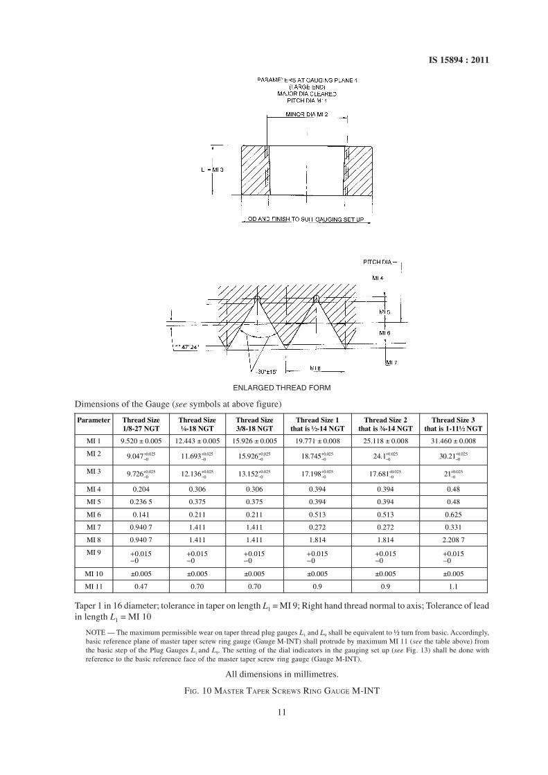
Dimensions of the Gauge (see symbols at above figure)
Parameter Thread Size 1/8-27 NGT
Thread Size ¼-18 NGT
Thread Size 3/8-18 NGT
Thread Size 1 that is ½-14 NGT
Thread Size 2 that is ¾-14 NGT
Thread Size 3 that is 1-11½
NGT
A1 9.52± 0.005 12.443± 0.005 15.926± 0.005 19.771 ± 0.008 25.118 ± 0.008 31.460 ± 0.008
A2 9.993 13.193 16.676 20.797 26.144 30.21
A3 0.0100.947+
− 0.01501.411+
− 0.01501.411
+- 0.025
01.814+- 0.025
01.814+- 0.025
02.208 7+-
A4 9.233 12.126 15.845 19.263 24.580 30.825
A5 00.0259.706+
− 00.02512.876+
− 00.02515.595+
− 00.02520.829+
− 00.02525.606+
− 00.02532.075+
−
A6 0.02500.947+
− 0.02501.411+
− 0.02501.411+
− 0.02501.814+
− 0.02501.814+
− 0.02502.2087+
−
A7 4.572 5.08 6.096 8.128 8.611 10.160
A8 0.940 7 1.411 1.411 1.814 1.814 2.208 7
A9 0.171 0.236 0.236 0.272 0.272 0.331
A10 0.236 5 0.375 0.375 0.513 0.513 0.625
All dimensions in millimetres.
FIG. 4 TAPER THREAD PLUG GAUGE TO CHECK PITCH DIAMETER IN CYLINDER NECK GAUGE ‘A’ (L1)

6
IS 15894 : 2011
ENLARGED THREAD FORM
TAPPER 1 IN 16 ON DIAMETER
TOLERANCE ON TAPER IN LENGTH +0.0150B6 =
TOLERANCE OF LEAD IN LENGTH B6 = ±0.005
Dimensions of the Gauge (see symbols at above figure)
Parameter Thread Size 1/8-27 NGT
Thread Size ¼-18 NGT
Thread Size 3/8-18 NGT
Thread Size 1 that is ½-14 NGT
Thread Size 2 that is ¾-14 NGT
Thread Size 3 that is 1-11½ NGT
B1 9.233±0.005 12.126 ± 0.005 15.845±0.005 19.263 ± 0.008 24.58 ± 0.008 30.825 ± 0.008
B2 9.901 13.126 16.845 20.551 25.865 32.393
B3 8.940 11.684 15.104 18.696 24.013 30.135
B4 00.0259.608+
− 00.02512.684+
− 00.02516.104+
− 00.02519.982+
- 00.02525.299+
− 00.02531.703 6+
-
B5 00.0259.276+
− 00.02512.136+
− 00.02513.152+
− 17.198 00.02517.681+
− 00.02521.2+
−
B6 4.70 7.06 7.06 9.070 9.070 11.043
B7 0.940 7 1.411 1.411 1.814 1.814 2.208 7
B8 0.073 0.111 0.111 0.142 0.142 0.172
B9 0.334 0.500 0.500 0.643 0.643 0.783
All dimensions in millimetres.
FIG. 5 FULL FORM TAPER THREAD PLUG GAUGE TO CHECK THREAD IN CYLINDER NECK GAUGE ‘B’ (L9)

7
IS 15894 : 2011
Dimensions of the Gauge (see symbols at above figure)
Parameter Thread Size 1/8-27 NGT
Thread Size ¼-18 NGT
Thread Size 3/8-18 NGT
Thread Size 1 that is ½-14 NGT
Thread Size 2 that is ¾-14 NGT
Thread Size 3 that is 1-11½ NGT
C1 00.0058.480+
− 00.00510.997+
− 00.00514.76+
− 00.00517.81+
− 00.00523.129+
− 00.00529.058+
−
C2 4.572 ± 0.038 5.08 ± 0.038 6.096 ± 0.038 8.128 ± 0.038 8.611 ± 0.038 10.160 ± 0.038
6.2 Full Form Screw Ring Gauge for CheckingRelative Engagement of Threads of Taper Stem L8
— Gauge E
See Fig. 8.
6.3 Plain Taper Ring Gauge for Checking CrestTruncation of External Threads on Stem —Gauge F
See Fig. 9.
7 DIMENSIONS AND TOLERANCES OFMASTER GAUGES
7.1 Master Taper Screw Ring Gauge to Check L1
(Gauge A) and L9 (Gauge B) Taper Thread PlugGauges — Gauge M-INT
See Fig. 10.
7.2 Master Taper Thread Plug Gauge to Check L1
(Gauge D) and L8 (Gauge E) Taper Screw RingGauges — Gauge M-EXT
See Fig. 11.
8 USAGE OF GAUGES
Usage of gauges is given in Annex A.
9 GENERAL REQUIREMENTS OF GAUGINGSURFACES
9.1 Hardness
Rockwell C 60 to 62 when determined according toIS 1586.
9.2 Finish
Gauging surfaces shall be ground and suitably stabilized.The method of stabilizing shall be as per agreementbetween the manufacturer and the customer. Surfacesother than the gauging surface shall be finished smooth.
10 DESIGNATION
The gauges shall be designated by:
Size of the thread, gauge type and number of this standard.
Example:
The screw ring gauge for checking pitch diameter oftaper stem at length L1 shall be designated as:
¾′′ × 14NGTL1 Gauge D, IS 15894
FIG. 6 PLAIN TAPER PLUG GAUGE TO CHECK CREST TRUNCATION IN CYLINDER NECK GAUGE ‘C’
All dimensions in millimetres.

8
IS 15894 : 2011
Dimensions of the Gauge (see symbols at above figure)
Parameter Thread Size 1/8-27 NGT
Thread Size ¼-18 NGT
Thread Size 3/8-18 NGT
Thread Size 1 that is ½-14 NGT
Thread Size 2 that is ¾-14 NGT
Thread Size 3 that is 1-11½ NGT
D1 0.02504.572+
− 0.02505.08+
− 0.02506.096+
− 0.02508.128+
− 0.02508.611+
− 0.025010.160+
−
D2 9.233 12.126 15.845 19.263 24.58 30.825
D3 8.76 11.376 15.095 18.236 23.553 29.575
D4 9.520 12.443 15.926 19.771 25.118 31.460
D5 0.0109.047+
− 0.015011.693+
− 0.015015.176+
− 0.025018.745+
− 0.025024.092+
− 0.025030.21+
−
D6 0.940 7 1.411 1.411 1.814 1.814 2.208 7
D7 0.236 5 0.375 0.375 0.513 0.513 0.625
D8 0.236 5 0.375 0.375 0.513 0.513 0.625
D9 0.171 0.236 0.236 0.272 0.272 0.331
All dimensions in millimetres.
FIG. 7 TAPER SCREW RING GAUGE TO CHECK TAPE THREADS ON VALVE STEM GAUGE ‘D’ (L1)
TAPER 1 IN 16 ON DIAMETER
TOLERANCE IN LENTH L1 = ± 0.023
RIGHT HAND THREAD NORMAL TO THE AXIS
TOLERANCE OF LEAD IN LENGTH L1 = ± 0.008

9
IS 15894 : 2011
Dimensions of the Gauge (see symbols at above figure)
Parameter Thread Size 1/8-27 NGT
Thread Size ¼-18 NGT
Thread Size 3/8-18 NGT
Thread Size 1 that is ½-14 NGT
Thread Size 2 that is ¾-14 NGT
Thread Size 3 that is 1-11½ NGT
E1 0.02509.202+
− 0.025011.972+
− 0.025015.457+
− 0.025019.166+
− 0.025024.513+
− 0.025030.72+
−
E2 9.870 12.972 16.457 20.452 25.799 32.288
E3 0.025010.216+
− 0.025013.546+
− 0.025014.562+
− 0.025019.014+
− 0.025019.497+
− 0.025023.411+
−
E4 5.64 8.47 8.47 10.886 10.886 13.252
E5 11.1 14.8 18.2 22.5 27.9 34.7
E6 9.233 12.126 15.545 19.263 24.58 30.825
E7 8.565 11.126 14.545 17.975 23.294 29.257
E8 0.073 0.111 0.111 0.142 0.142 0.172
E9 0.334 0.500 0.500 0.643 0.643 0.784
E10 0.334 0.500 0.500 0.643 0.643 0.784
E11 0.073 0.111 0.111 0.142 0.142 0.172
E12 0.940 7 1.411 1.411 1.814 1.814 2.208 7
All dimensions in millimetres.
FIG. 8 FULL FORM TAPER SCREW RING GAUGE TO CHECK THREAD IN VALVE STEM GAUGE ‘E’ (L8)

10
IS 15894 : 2011
Dimensions of the Gauge (see symbols at above figure)
Parameter Thread Size 1/8-27 NGT
Thread Size ¼-18 NGT
Thread Size 3/8-18 NGT
Thread Size 1 that is ½-14 NGT
Thread Size 2 that is ¾-14 NGT
Thread Size 3 that is 1-11½ NGT
F1 4.572 ± 0.025 5.080 ± 0.025 6.096 ± 0.038 8.128 ± 0.038 8.611 ± 0.038 10.160 ± 0.038
F2 00.00510.272+
− 00.00513.572+
− 00.00517.005+
− 00.00521.221+
− 00.00526.568+
− 00.00533.227+
−
All dimensions in millimetres.
FIG. 9 PLAIN TAPER RING GAUGE TO CHECK CREST TRUNCATION OF EXTERNAL THREAD GAUGE ‘F’
11 CORROSION PROTECTION AND PACKING
Gauges shall be protected against climatic conditionsby application of any anti-corrosive coating. Packingshall be suitable to prevent damage in transit.
12 MARKING
12.1 The gauge shall be marked with the following:
a) Designation,
b) Manufacturer’s name or trade-mark, and
c) Serial number.
12.2 BIS Certification Marking
Each gauge may also be marked with the StandardMark.
12.2.1 The use of BIS certification mark is governedby the provisions of Bureau of Indian Standards Act,1986 and the Rules and Regulations made thereunder.The details of conditions under which the license forthe use of Standard Mark may be granted tomanufacturers or producers may be obtained from theBureau of Indian Standards.
11
IS 15894 : 2011
ENLARGED THREAD FORM
Dimensions of the Gauge (see symbols at above figure)
Parameter Thread Size 1/8-27 NGT
Thread Size ¼-18 NGT
Thread Size 3/8-18 NGT
Thread Size 1 that is ½-14 NGT
Thread Size 2 that is ¾-14 NGT
Thread Size 3 that is 1-11½ NGT
MI 1 9.520 ± 0.005 12.443 ± 0.005 15.926 ± 0.005 19.771 ± 0.008 25.118 ± 0.008 31.460 ± 0.008
MI 2 0.02509.047+
− 0.025011.693+
− 0.025015.926+
− 0.025018.745+
− 0.025024.1+
− 0.025030.21+
−
MI 3 0.02509.726+
− 0.025012.136+
− 0.025013.152+
− 0.025017.198+
− 0.025017.681+
− 0.025021+
−
MI 4 0.204 0.306 0.306 0.394 0.394 0.48
MI 5 0.236 5 0.375 0.375 0.394 0.394 0.48
MI 6 0.141 0.211 0.211 0.513 0.513 0.625
MI 7 0.940 7 1.411 1.411 0.272 0.272 0.331
MI 8 0.940 7 1.411 1.411 1.814 1.814 2.208 7
MI 9 0.0150
+- 0.015
0+- 0.015
0+- 0.015
0+- 0.015
0+- 0.015
0+-
MI 10 ±0.005 ±0.005 ±0.005 ±0.005 ±0.005 ±0.005
MI 11 0.47 0.70 0.70 0.9 0.9 1.1
Taper 1 in 16 diameter; tolerance in taper on length L1 = MI 9; Right hand thread normal to axis; Tolerance of leadin length L1 = MI 10
NOTE — The maximum permissible wear on taper thread plug gauges L1 and L9 shall be equivalent to ½ turn from basic. Accordingly,basic reference plane of master taper screw ring gauge (Gauge M-INT) shall protrude by maximum MI 11 (see the table above) fromthe basic step of the Plug Gauges L1 and L9. The setting of the dial indicators in the gauging set up (see Fig. 13) shall be done withreference to the basic reference face of the master taper screw ring gauge (Gauge M-INT).
All dimensions in millimetres.
FIG. 10 MASTER TAPER SCREWS RING GAUGE M-INT

12
IS 15894 : 2011
Dimensions of the Gauge (see symbols at above figure)
Parameter Thread Size 1/8-27 NGT
Thread Size ¼-18 NGT
Thread Size 3/8-18 NGT
Thread Size 1 that is ½-14 NGT
Thread Size 2 that is ¾-14 NGT
Thread Size 3 that is 1-11½ NGT
ME1 9.233 ± 0.005 12.126 ± 0.005 15.545 ± 0.005 19.263 ± 0.008 24.58 ± 0.008 30.825 ± 0.008
ME2 00.0259.706+
− 00.02512.876+
− 00.02516.295+
− 00.02520.289+
− 00.02525.606+
− 00.02532.075+
−
ME3 0.025010.216+
− 0.025013.546+
− 0.025014.562+
− 0.025019.041+
− 0.025019.497+
− 0.025023.411+
−
ME4 0.204 0.306 0.306 0.394 0.394 0.48
ME5 0.204 0.306 0.306 0.394 0.394 0.48
ME6 0.2365 0.375 0.375 0.513 0.513 0.625
ME7 0.141 0.211 0.211 0.272 0.272 0.331
ME8 0.940 7 1.411 1.411 1.814 1.814 2.208 7
ME9 0.0080
+- 0.01
0+- 0.01
0+- 0.015
0+- 0.015
0+- 0.02
0+-
ME10 ±0.005 ±0.005 ±0.005 ±0.005 ±0.005 ±0.008
ME11 0.47 0.70 0.70 0.9 0.9 1.1
Taper 1 in 16 diameter; tolerance in taper on length L1 = ME 9; Right hand thread normal to axis; Tolerance oflead in length L1 = ME 10
NOTE — The maximum permissible wear on taper thread plug gauges L1 and L8 shall be equivalent to ½ turn from basic. Accordingly,basic reference plane of master taper screw ring gauge (Gauge M-EXT) shall protrude by maximum ME 11 (see the table above) fromthe basic step of the Ring Gauges L1 and L8. The setting of the dial indicators in the gauging set up (see Fig. 12) shall be done withreference to the basic reference face of the master taper screw ring gauge (Gauge M-EXT).
All dimensions in millimetres.
FIG. 11 MASTER TAPER THREAD PLUG GAUGE ‘M-EXT’

13
IS 15894 : 2011
ANNEX A
(Clause 8)
USAGE OF GAUGES
A-0 Special gauges are required for the gauging of thesethreads because of their length and rigid requirementfor sealing the compressed gas against leakage.
A-1 PITCH DIAMETER OF EXTERNALTHREAD
To check the size of external thread for pitch diameter,the taper screw ring gauge D is used. This gauge D(also known as L1 ring gauge) is the primary gaugebecause the reading taken on this gauge will be neededfor use when additional gauging is done.
A-1.1 The taper screw ring gauge E (also known as L8
ring gauge) is used to check the taper of the externalthreads. It is screwed on to the valve stem thread and itsengagement relative to that of L1 ring read at A-1 is noted.
A-2 CREST TRUNCATION OF EXTERNALTHREAD
To check the crest truncation of external thread, theplain taper ring gauge F (also known as truncationgauge) is used. This gauge is placed over the taperthread and the engagement relative to that of L1 ringread at A-1 is checked.
A-3 Gauging of the thread with the three ring gauges(see Fig. 7 to Fig. 9) is illustrated hereunder:
a) To set the L1 and L8 taper screw ring gauges(gauges D and E respectively), use the mastertaper thread plug gauge M-EXT (see Fig. 11)screwed into the rings and set the reading onthe dial indicator at zero with the plunger tipon the indicator resting against small end ofthe master taper thread plug ensuring that thewhole millimetre readings on the small dialsis also equal on both the dials.
b) The master taper thread plug gauge be thenunscrewed till the small end of the gaugematches with the basic reference face of theL1 and L8 gauges. The dial readings shall berecorded and compared with the set value asin A-3 (a). The difference shall be maximumME11 (see Fig. 11).
c) To set the plain taper truncation ring (gaugeF), insert the setting distance piece (seeFig. 12) in to the gauge with the face ‘X’ ofthe setting plug pressed against the large endface of the truncation ring. Set the plunger tip
of the dial indicator against the face ‘Y’ of thesetting plug and adjust the dial at zeroensuring that the whole millimetre readingson the small dial is identical to that on thesmall dials of the two gauges as given inA-3 (a).
d) Screw the valve stem in taper screw ring Dand note the reading on dial indicator. Thereading should be zero (as set on the dialindicator) ± A-3(c)1 mm (see Table 1 forvalue) for the purpose of acceptability of thethread size. Note this reading as R(Ext)L1
e) Screw the valve stem into gauge E. Thereading on the dial indicator should be
( ) ( )1+A-3 d 1
Ext L -0R (see Table 1 for value) for the
purpose of acceptability of the requirementof relative engagement (see 4.5).
f) Place the valve stem in to the plain taper ringgauge F. The reading on the dial indicator
should be ( ) ( )1
+A-3 e 1Ext -0L
R (see Table 1 for value)
for the purpose of acceptability of the cresttruncation of the thread.
A-4 PITCH DIAMETER OF INTERNALTHREAD
To check the size of the internal thread for pitchdiameter, the taper thread plug gauge A is used. Thisgauge A (also known as L1 plug gauge) is the primarygauge because the reading taken on this gauge will beneeded for use when additional gauging is done.
A-4.1 The gauge B (also known as L9 plug gauge) isused to check the engagement relative to that with L1
plug.
A-5 CREST TRUNCATION OF INTERNALTHREAD
To check the crest truncation of the internal thread,the plain taper plug gauge C (also known as truncationgauge) is used. This gauge is placed in to the internalthread and the engagement relative to that with L1 plugis checked.
A-6 The gauging of the internal threads with thesegauges as stated above is illustrated hereunder withreference to Fig. 13:

14
IS 15894 : 2011
a) Using the master taper screw ring shown inFig. 10 and the plunger tips of the respectivedial indicators resting against the face of themaster ring, set the readings on all the dialindicators at zero ensuring that the wholemillimeter readings on the small dials is alsoequal on all the three dials.
b) The master taper screw ring gauge be thenunscrewed till the face of the master ring matcheswith the small end of the L1 and L9 gauges. Thedial readings shall be recorded and comparedwith the set value as in (a). The difference shallbe maximum MI 11 (see Fig. 10).
c) Screw the taper thread plug gauge A in to theinternal thread to be gauged. The readingshould be zero ± A-6(b)1 mm (see Table 1for value) for the purpose of acceptability ofthe thread size. Note the reading on the dialindicator as ( ) 1Int LR .
d) Screw the taper thread plug gauge B in to theinternal thread being gauged. The reading on
the dial indicator should be ( ) ( )1
+0Int L -A-6 c 1
R
(see Table 1 for value) for the purpose ofacceptability of meeting the requirement ofrelative engagement (see 4.5).
e) Place the plain taper plug gauge C in to theinternal thread being gauged. The reading onthe dial indicator should be ( )
( )1
+A-6 d 1Int L -0R (see
Table 1 for value) for the purpose ofacceptability of meeting the requirement ofcrest truncation of the thread.
Table 1 Values of Parameters(Clauses A-3 and A-6)
Sl No.
Parameter Thread Size 1 that is ½–14
NGT
Thread Size 2 that is ¾-14
NGT
Thread Size 3 that is 1 –11½
NGT
(1) (2) (3) (4) (5)
i) A-3(c)1 1.814 1.814 2.208 7 ii) A-3(d)1 1.814 1.814 2.208 7
iii) A-3(e)1 2.6 2.6 3.2 iv) A-6(b)1 1.814 1.814 2.208 7 v) A-6(c)1 1.814 1.814 2.208 7
vi) A-6(d)1 2.6 2.6 3.2
NOTE — All dimensions in millimetres.
Parameter Thread Size 1/8-27 NGT
Thread Size ¼-18 NGT
Thread Size 3/8-18 NGT
Thread Size 1 that is ½-14 NGT
Thread Size 2 that is ¾-14 NGT
Thread Size 3 that is 1-11½ NGT
Fig. 12(1) 4.572 5.080 6.096 8.128 8.611 10.160
FIG. 12 GAUGING SET-UP TO CHECK EXTERNAL TAPER THREADS ON VALVE STEM

15
IS 15894 : 2011
FIG. 13 GAUGING SET-UP TO CHECK INTERNAL TAPER THREADS IN CYLINDER NECK
ANNEX B(Foreword)
COMMITTEE COMPOSITION
Gas Cylinders Sectional Committee, MED 16
Organization Representative
Petroleum and Explosive Safety Organization, Nagpur SHRI AJAI NIGAM (Chairman)SHRI D. K. GUPTA (Alternate)
All India Industrial Gases Manufacturers Association, SHRI KARAN BHATIA
New Delhi SHRI VEENA PETER (Alternate)
Bharat Petroleum Corporation Ltd, Mumbai SHRI THARIYAN GEORGE
SHRI SANJAY PHULLI (Alternate)
Bharat Pumps and Compressors Ltd, Allahabad SHRI J. P. SINHA
SHRI P. G. CHOUDHURY (Alternate)
BOC India Ltd, Kolkata SHRI K. MANOHARAN
SHRI RAMANA VUTUKURU (Alternate)
Everest Kanto Cylinder Ltd, Mumbai SHRI P. M. SAMVATSAR
SHRI A. K. KHAMKAR (Alternate)
Hindustan Petroleum Corporation Ltd, Mumbai SHRI P. P. NADKARNI
SHRI ALOK KUMAR GUPTA (Alternate)
Indian Oil Corporation Ltd, Mumbai SHRI S. S. SAMANT
SHRI RAJESH HAZARNIS (Alternate)
International Industrial Gases Ltd, Kolkata SHRI DEVENDRA K. GARG
SHRI NIKHILESh K. GARG (Alternate)
Kabsons Gas Equipments Ltd, Hyderabad SHRI SATISH KABRA
SHRI S. GOPALAIAH (Alternate)
Kosan Industries Ltd, Mumbai/Surat SHRI S. K. DEY
SHRI S. B. BOLMAL (Alternate)
LPG Equipment Research Centre, Bangalore SHRI G. P. GUPTA
SHRIMATI KAROBI MUKHERJEE (Alternate)
Mahanagar Gas Limited, Mumbai SHRI RAGHUNATH KULAI
SHRI ARUN NAYAK (Alternate)
Maruti Koatsu Cylinders Ltd, Mumbai SHRI NITIN J. THAKKAR
SHRI A. S. SARAN (Alternate)
Ministry of Defence (DGQA), Pune SHRI J. P. TIWARI
LT COL B. V. RAVI KUMAR (Alternate)
Praxair India Ltd, Bangalore SHRI MILAN SARKAR
SHRI ARINDAM DAS (Alternate)
Research & Development Estt (Engineers), Pune SHRI P. K. CHATTOPADHYAY
SHRI A. BASU (Alternate)

Organization Representative
Sakha Engineers Pvt Ltd, New Delhi SHRI AMARJIT S. KOHLI
SICGIL India Ltd, Chennai SHRI FAROOQUE DADABHOY
SHRI R. PADMANABAN (Alternate)
Steel Authority of India Ltd, Salem SHRI T. KALYANASUNDARAM
SHRI N. K. VIJAYAVARGIA (Alternate)
Steel Authority of India Ltd, Ranchi SHRI DEBASHIS KARMAKAR
DR B. K. JHA (Alternate)
Supreme Cylinders Ltd, Delhi SHRI M. L. FATHEPURIA
Tekno Valves, Kolkata SHRI Y. K. BEHANI
SHRI R. BEHANI (Alternate)
Trans Valves (India) Pvt Ltd, Hyderabad SHRI A. K. JAIN
SHRI ANUJ JAIN (Alternate)
Vanaz Engineers Ltd, Pune SHRI S. K. KHANDEKAR
SHRI S. R. SARVATE (Alternate)
In personal capacity (Menon & Patel, 14/1, Mile, Mathura SHRI EBRAHIM M. PATEL
Road, Faridabad)
In personal capacity (303, Shantikunj, Pandav Bunglows Lane SHRI L. D. THAKKAR
Athwalines, Surat)
BIS Directorate General SHRI C. K. VEDA, Scientist ‘F’ and Head (MED)[Representing Director General (Ex-officio)]
Member SecretarySHRI VISHAL TOMER
Scientist ‘C’ (MED)
Gas Cylinder Valves and Fittings Subcommittee, MED 16 : 1
In personal capacity (303, Shantikunj, Athwalines, Surat) SHRI L. D. THAKKAR (Convener)
ACE LPG Car Kits Ltd, Thane SHRI AMIT SHAH
SHRI MANOJ VITHALANI (Alternate)
All India Gases Manufacturers Association, Vadodara SHRI KARAN BHATIA
SHRI VEENA PETER (Alternate)
Batra Associates Limited, Faridabad SHRI N. K. SAWHNEY
Bharat Petroleum Corporation Ltd, Mumbai SHRI THARIYAN GEORGE
SHRI SANJAY PHULLI (Alternate)
Everest Kanto Cylinder Ltd, Mumbai SHRI P. M. SAMVATSAR
SHRI A. G. KHAMKAR (Alternate)
Hindustan Petroleum Corporation Ltd, Mumbai SHRI P. P. NADKARNI
SHRI ALOK KUMAR GUPTA (Alternate)
Indian Oil Corporation Ltd, Mumbai SHRI S. S. SAMANT
SHRI RAJESH HAZARNIS (Alternate)
Kabsons Gas Equipments Ltd, Hyderabad SHRI SATISH KABRA
SHRI SATYANARAYAN SONI (Alternate)
Kosan Industries Ltd, Mumbai SHRI S. K. DEY
SHRI S. B. BOLMAL (Alternate)
LPG Equipment Research Centre, Bangalore SHRI G. P. GUPTA
SHRIMATI KAROBI MUKHERJEE (Alternate)
Neema Forge Press Pvt Ltd, Nagpur SHRI G. L. NEEMA
SHRI AJAY MIRANI (Alternate)
Petroleum and Explosive Safety Organization, Nagpur SHRI AJAI NIGAM
SHRI D. K. GUPTA (Alternate)
Southern Metals and Alloys Pvt Ltd, Mumbai SHRI VINOD NORONHA
SHRI VIVEK NORONHA (Alternate)
Tekno Valves, Kolkata SHRI Y. K. BEHANI
SHRI R. BEHANI (Alternate)
Trans Valves (India) Pvt Ltd, Hyderabad SHRI A. K. JAIN
SHRI ANUJ JAIN (Alternate)
Vanaz Engineers Pvt Ltd, Pune SHRI S. K. KHANDEKAR
SHRI S. R. SARVATE (Alternate)

Gas Cylinders Sectional Committee, MED 16
FOREWORD
This Indian Standard was adopted by the Bureau of Indian Standards, after the draft finalized by the Gas CylindersSectional Committee had been approved by the Mechanical Engineering Division Council.
Currently IS 9687 and IS 9121 are available for the gauges to check the threads of Size 1 and Size 2 respectively.However, no Indian Standard is available at present for the gauges to check Size 3 threads. It has, therefore, beenconsidered necessary that a composite Indian Standard be prepared to cover the gauges to check the threads of allthe three sizes. This standard supersedes IS 9687 : 1980 ‘Specification for inspection gauges for checking Type 1(Size 1) taper threads of gas cylinder valves, Taper 1 in 16’ and IS 9121 : 2005 ‘Inspection gauges for checkingType 1 (Size 2) taper threads of gas cylinder valves, Taper 1 in 16 — Specification (first revision)’. The standardsIS 9687 and IS 9121 stands withdrawn.
Taper threads of gas cylinder valve stems and cylinder necks as per Type 1 Sizes 1, 2 and 3 having taper 1 in 16on diameter are provided in IS 3224 : 2002 ‘Valve fittings for compressed gas cylinders excluding liquefiedpetroleum gas (LPG) cylinders’ and Type 1 Size 2 threads are standardized in IS 8737 : 1995 ‘Valve fittings andcylinders for use with liquefied petroleum gas (LPG) cylinders of more than 5 litre water capacity’.
These threads conform to the NGT threads as per ANSI/CSA/CGA STANDARD V-1 — 1987 ‘Compressed gascylinder valve outlet and inlet connection’ issued by American National Standard Institute and Compressed GasAssociation, Inc., this being the specification forming the basis of these threads standard. Relevant portions ofthe specification of the threads have been reproduced standard. With this requirement to inspect the taper of thethreads, the method of checking relative engagement of the product threads in the threaded and plain taper ringgauges has been included in this draft specification.
For the purpose of deciding whether a particular requirement of this standard is complied with, the final value,observed or calculated, expressing the result of a test or analysis, shall be rounded off in accordance with IS 2 : 1960‘Rules for rounding off numerical values (revised)’. The number of significant places retained in the rounded offvalue should be the same as that of the specified value in this standard.

Bureau of Indian Standards
BIS is a statutory institution established under the Bureau of Indian Standards Act, 1986 to promoteharmonious development of the activities of standardization, marking and quality certification of goodsand attending to connected matters in the country.
Copyright
BIS has the copyright of all its publications. No part of these publications may be reproduced in any formwithout the prior permission in writing of BIS. This does not preclude the free use, in the course ofimplementing the standard, of necessary details, such as symbols and sizes, type or grade designations.Enquiries relating to copyright be addressed to the Director (Publications), BIS.
Review of Indian Standards
Amendments are issued to standards as the need arises on the basis of comments. Standards are also reviewedperiodically; a standard along with amendments is reaffirmed when such review indicates that no changes areneeded; if the review indicates that changes are needed, it is taken up for revision. Users of Indian Standardsshould ascertain that they are in possession of the latest amendments or edition by referring to the latest issue of‘BIS Catalogue’ and ‘Standards : Monthly Additions’.
This Indian Standard has been developed from Doc No.: MED 16 (0982).
Amendments Issued Since Publication
Amend No. Date of Issue Text Affected
BUREAU OF INDIAN STANDARDS
Headquarters:
Manak Bhavan, 9 Bahadur Shah Zafar Marg, New Delhi 110 002Telephones : 2323 0131, 2323 3375, 2323 9402 Website: www.bis.org.in
Regional Offices: Telephones
Central : Manak Bhavan, 9 Bahadur Shah Zafar Marg 2323 7617NEW DELHI 110002 2323 3841
Eastern : 1/14 C.I.T. Scheme VII M, V. I. P. Road, Kankurgachi 2337 8499, 2337 8561KOLKATA 700054 2337 8626, 2337 9120
Northern : SCO 335-336, Sector 34-A, CHANDIGARH 160022 60 384360 9285
Southern : C.I.T. Campus, IV Cross Road, CHENNAI 600113 2254 1216, 2254 14422254 2519, 2254 2315
Western : Manakalaya, E9 MIDC, Marol, Andheri (East) 2832 9295, 2832 7858MUMBAI 400093 2832 7891, 2832 7892
Branches: AHMEDABAD. BANGALORE. BHOPAL. BHUBANESHWAR. COIMBATORE. DEHRADUN.FARIDABAD. GHAZIABAD. GUWAHATI. HYDERABAD. JAIPUR. KANPUR. LUCKNOW.NAGPUR. PARWANOO. PATNA. PUNE. RAJKOT. THIRUVANANTHAPURAM.VISAKHAPATNAM.
�
�
�
�
�
Published by BIS, New Delhi