Embed Size (px)
Citation preview

IRF2.0 Technology White Paper
Hangzhou H3C Technologies Co., Ltd. 1/24
IRF2.0 Technology White Paper
Keywords: IRF, topology collection, role election, high reliability, redundant backup
Abstract: Intelligent Resilient Framework (IRF) allows you to build an IRF virtual device by interconnecting
multiple devices. You can manage the member devices of the IRF virtual device as a whole. This
manual describes how to establish an IRF virtual device and the IRF applications.
Acronyms:
Acronym Full spelling
IRF Intelligent Resilient Framework

IRF2.0 Technology White Paper
Hangzhou H3C Technologies Co., Ltd. 2/24
Table of Contents
Overview···························································································································································3 Background ················································································································································3 Advantages ················································································································································4
Technology Implementation···························································································································5 Basic Concepts ··········································································································································5 Software Architecture·································································································································6 Establishing an IRF Virtual Device·············································································································7
Physical Connections ·························································································································7 Topology Collection····························································································································8 Role Election ······································································································································9
Managing an IRF Virtual Device ··············································································································11 Configuration Synchronization ·········································································································11 Member ID········································································································································12
Maintaining an IRF Virtual Device············································································································12 Joining of a Member Device·············································································································12 Leaving of a Member Device············································································································13 Topology Update ······························································································································13
Software Auto Upgrade····························································································································14
High Reliability···············································································································································14 1:N Backup···············································································································································14 Protocol Hot Backup ································································································································14 Uplink/Downlink Backup···························································································································16 IRF Port Backup·······································································································································16
Packet Forwarding Mechanism····················································································································17
Technical Characteristics ·····························································································································19 Generic Logical Software Architecture·····································································································19 Mature System Architecture·····················································································································19 Streamlined Chassis-Type Distributed Device ························································································20 Rich and Stable Function Support ···········································································································20 Effective 1:N Backup································································································································20 Redundancy Protection on a Single Chassis-Type Distributed Device ···················································21 Flexible Device Connections····················································································································21
Application Scenarios···································································································································21 Increasing Port Number ···························································································································21 Expanding System Processing Capability ·······························································································21 Expanding Bandwidth ······························································································································22 Connecting Devices Located Far from Each Other ·················································································22 Simplifying Networking·····························································································································23
IRF2.0 Technology White Paper
Hangzhou H3C Technologies Co., Ltd. 3/24
Overview
Background At present, communication devices fall into two categories: box-type devices and chassis-type distributed devices. They present these differences:
Box-type devices are cost-effective, but are not highly reliable, lack of uninterrupted service protection, and are not suitable for important scenarios, such as core layer, distribution layer, production network, and data center. In a complicated networking environment, box-type devices are not scalable, which means users have to maintain more network devices and change the original network topology.
Chassis-type distributed devices are highly reliable and provide high performances and high port-density. They are always deployed in some important scenarios, such as at the core layer, distribution layer, production network, and data center. However, they cost high for the first operation and for each port.
The IRF technology emerged as a result, combining the advantages of box-type devices and chassis-type distributed devices. IRF allows you to build an IRF virtual device by interconnecting multiple devices through IRF ports, as shown in Figure 1. You can manage all the member devices by managing the IRF virtual device, which is cost-effective like a box-type device, and scalable and highly reliable like a chassis-type distributed device.
Figure 1 IRF networking
IP network
IRF virtual device
IP network
IRF linkEqual to
Master Slave
The virtualization technology has been developing and changing continuously since its emergence, and different vendors adopt various technology implementations. They have the following common problems:

IRF2.0 Technology White Paper
Hangzhou H3C Technologies Co., Ltd. 4/24
Providing less functions. Most vendors adopt new system architectures to implement virtualization. Therefore, only some basic functions are supported, and many value-added services may not be provided.
Different functionalities. Users must be familiar with the differences before they use products supporting virtualization, especially when using them to establish a network along with other products because of different architectures. This helps device management and maintenance and increases maintenance cost.
Unstable system operation. For example, each member has independent control capability; therefore, how to coordinate the control packets of the members is a problem. Another example, the status of each member is the same and each member is capable of communicating with other members. Then, when the number of the members increases, the intercommunication among members increases with geometric series, known as the N² problem. These system-related problems need to be resolved by adopting new technologies. However, these new technologies are immature, which will affect the product performance and running reliability.
IRF is an H3C-proprietary technology. After the release of the IRF1.0, H3C released IRF2.0, which provides more functions. Unless otherwise noted, IRF mentioned in the following sections refers to IRF2.0, and the following technology implementations and configuration examples are for IRF2.0.
Advantages IRF features the following advantages:
Simplified topology and streamlined management. An IRF virtual device appears as a node on the network. You can log in to it by connecting to any port of any member to manage all members of the IRF virtual device.
Simple network operation. Various control protocols running on different member devices as if they are running on one device. For example, routing protocols calculate the routes of the IRF virtual device instead of calculating the routes of each member. This avoids a great number of protocol packet exchanges among the members, simplifies network operation, and shortens the convergence time during network flapping. In addition, this advantage of the IRF technology is not delivered by the common cluster technology, which only realizes the unified management of devices, and the devices in a cluster operate as independent nodes.
Low cost. The IRF technology creates an IRF virtual device from multiple low-end devices, and thus the IRF virtual device has a higher port density and bandwidth and costs lower than using high-end devices.
Powerful network expansion capability. By adding member devices, the number of IRF ports, network bandwidth, and processing capability of the IRF virtual device can be easily expanded.
Protecting investment. Users only need to add new devices rather than replacing the original ones when upgrading a network because of the powerful network expansion capability of the IRF virtual device.
High reliability. IRF provides both link and node redundancy. An IRF virtual device comprises multiple member devices that operate in 1:N redundancy: the master runs, manages and maintains the IRF virtual device, whereas the slaves process services as well as functioning as the backups. As soon as the master fails, the IRF virtual device immediately elects a new master to prevent service interruption. In addition, you can aggregate both IRF links of members and the links between the IRF virtual device and its upper or lower layer devices.

IRF2.0 Technology White Paper
Hangzhou H3C Technologies Co., Ltd. 5/24
High resiliency. You can increase the bandwidth and processing capability of an IRF virtual device simply by adding member devices. Each member device has its own CPU and they independently process and forward protocol packets.
Diversified functions. IRF provides all features supported by a switch, such as IPv4, IPv6, MPLS, security features, OAA cards, high availability, which can run effectively and stably on the IRF virtual device, and thus expands the application of IRF virtual devices.
Comprehensive product support. An IRF virtual device can be created from box-type devices or chassis-type distributed devices.
Technology Implementation
Basic Concepts
Role
The devices that form an IRF virtual device are called member devices. Each of them plays either of the following two roles:
Master: Manages the IRF virtual device. Slave: All members that operate as the backups of the master are called slaves. When the
master fails, the IRF virtual device automatically elects a new master from one of the slaves.
Master and slaves are elected through the role election mechanism. An IRF virtual device has only one master at a time. Other members are the slaves.
IRF port
An IRF port is a logical port dedicated to the internal connection of an IRF virtual device. An IRF port can be numbered as IRF-port1 or IRF-port2. An IRF port is effective only after it is bound to a physical IRF port.
Physical IRF ports
Physical ports used for connecting members of an IRF virtual device are called physical IRF ports. Physical IRF ports can be ports dedicated to the IRF virtual device, Ethernet ports or optical ports (which ports can serve as physical IRF ports depends on the device model.).
Typically, an Ethernet port or optical port forwards packets to the network. When bound to an IRF port, it acts as a physical IRF port and forwards data traffic such as IRF-related negotiation packets and data traffic among member devices.
IRF virtual device merge
As shown in Figure 2, two IRF virtual devices operate independently and steadily. Connect them physically and perform necessary configurations to make them form one IRF virtual device. This process is called IRF virtual device merge.

IRF2.0 Technology White Paper
Hangzhou H3C Technologies Co., Ltd. 6/24
Figure 2 IRF merge diagram
IRF virtual device partition
As shown in Figure 3, when an IRF virtual device is formed, the failure of the IRF link causes physical disconnection between the two members, and then the IRF virtual device is divided into two IRF virtual devices. This process is called IRF virtual device partition.
Figure 3 IRF split diagram
Member priority
Member priority determines the role of a member during a role election process. A member with a higher priority is more likely to be a master. The priority of a device defaults to 1. You can modify the priority at the CLI.
Software Architecture The system architecture of an IRF virtual device is as shown in Figure 4.
IRF virtualization: This module automatically collects IRF topology, performs role election, and creates an IRF virtual device from multiple member devices.
Hardware: Hardware components. Device management: The management layer of the device and manages the device resources
like main boards and cards. The word device here refers to both the hardware and the IRF virtual device.
System management and application modules: All management and control programs running on the device, for example, various routing protocol modules, and link layer protocol modules.
The IRF virtualization module creates an IRF virtual device, and the device management module manages both the IRF virtual device and physical devices and masks their differences. The application software does not care about the differences on the physical layer and does not need to modify its internal mechanism or interfaces.

IRF2.0 Technology White Paper
Hangzhou H3C Technologies Co., Ltd. 7/24
Figure 4 IRF software architecture
Device management
IRF virtualization
System management and application modules
Hardware
Establishing an IRF Virtual Device
Physical Connections
Preparing for connecting physical IRF ports
To establish an IRF virtual device, physically connect the physical IRF ports of member devices. The connection medium depends on the physical IRF ports supported by the device.
If you use IRF-dedicated ports as physical IRF ports, use IRF cables to connect them. This connection mode can provide high reliability and performance for packet exchange between member devices.
If you use common Ethernet interfaces as physical IRF ports, use network cables (cross-over or straight-through) to connect them. This connection mode improves the usage of the available resources (common Ethernet interfaces are used to forward data traffic when not bound to any IRF port, and used to forward packets between member devices when bound to IRF ports), and saves the cost as well (without the need to purchase any interface card or optical module used for IRF connection).
If you use optical ports as physical IRF ports, use fibers to connect them. This connection mode can connect physical devices located very far from each other and provide flexible application.
Connecting physical IRF ports
As shown in Figure 5, connect IRF-Port1 on one device to the physical port bound with the IRF-Port2 on its neighbor device.

IRF2.0 Technology White Paper
Hangzhou H3C Technologies Co., Ltd. 8/24
Figure 5 IRF virtual device physical connection
IRF topology
An IRF virtual device typically adopts daisy chain connection or ring connection, as shown in Figure 6.
A daisy chain connection is mainly used in a network where member devices are distributedly located.
A ring connection is more reliable than the daisy chain connection. In a daisy chained IRF virtual device, the failure of one link can cause the IRF virtual device to partition into two independent IRF virtual devices; where the failure of a link in a ring connection result in a daisy chain connection, not affecting IRF services.
Figure 6 IRF connections
Topology Collection
Each member exchanges hello packets with the directly connected neighbors to collect topology of the IRF virtual device. The hello packets carry the topology information, including IRF port connection states, member IDs, priorities, and bridge MAC addresses.
Each member is managed by its active main board (AMB), which records its known topology information locally. At the startup of a member device, the AMB of the member device records topology information of the member device. When an IRF port of the member device becomes up, the AMB of the member device performs the following operations:

IRF2.0 Technology White Paper
Hangzhou H3C Technologies Co., Ltd. 9/24
1) Periodically sends its known topology information from this port. 2) Upon receiving the topology information from the directly connected neighbor, it updates the local
topology information. 3) If a standby main board (SMB) is available on the member device, the AMB synchronizes its
recorded topology information to the SMB to ensure that the topology information on both boards is consistent.
After topology collection lasts for a period of time, all members have obtained the complete topology information (known as topology convergence), and then the IRF virtual device enters the next stage: role election.
Role Election
The process of defining the role (master or slave) of members is role election.
Role election is held when the topology changes, such as, forming an IRF virtual device, adding a new member, leaving or failure of the master, or IRF virtual device merge. The master is elected based on the rules below, in the order specified. If the first rule does not apply, a second rule is tried, and so on, until the only winner is found.
The current master, even if a new member has a higher priority. (When an IRF virtual device is being formed, all member devices consider themselves as the master, so this principle is skipped)
The device with higher priority. The device with the longest system up-time. (The system up-time information of each member
device is delivered in IRF hello packets) The member with the lowest bridge MAC address.
After role election, an IRF virtual device is established:
An IRF virtual device that comprises box-type devices operates like a chassis-type distributed device. The master operates as the AMB of the IRF virtual device, and the slaves operate as the SMBs (also operate as interface cards), as shown in Figure 7.

IRF2.0 Technology White Paper
Hangzhou H3C Technologies Co., Ltd. 10/24
Figure 7 Box-type device virtualization schematic diagram
An IRF virtual device that comprises chassis-type distributed devices also operates like a chassis-type distributed device. It has more SMBs and interface cards. The AMB of the master is the AMB of the IRF virtual device, and the SMBs of the master, the AMB and SMBs of the slaves are the SMBs (also operate as interface cards) of the IRF virtual device, as shown in Figure 8.

IRF2.0 Technology White Paper
Hangzhou H3C Technologies Co., Ltd. 11/24
Figure 8 Chassis-type distributed device virtualization schematic diagram
Managing an IRF Virtual Device
Configuration Synchronization
IRF configuration synchronization involves two steps: batch synchronization at initialization and real-time synchronization in steady operation.
Batch synchronization
When multiple devices form an IRF virtual device, a master is elected the first. The master uses its configuration file to start up. Then the master synchronizes its configuration to all the slaves. When the slaves are initialized, the IRF virtual device is established. During the operation of the IRF virtual device, when a new member joins the IRF virtual device, the master also performs batch synchronization. The new member restarts and joins the IRF virtual device as a slave. Then the master synchronizes its configuration in batches to the new member. The new member initializes with the synchronized configuration, without reading its local startup configuration file.
Real-time synchronization
After all member devices initialize, the IRF virtual device operates as a single device in the network. Users can log in on the console port or through telnet to any member device of the IRF virtual device to manage and configure the IRF virtual device. As the management core of the IRF virtual device,

IRF2.0 Technology White Paper
Hangzhou H3C Technologies Co., Ltd. 12/24
the master responds to users’ login requests. Users perform configuration on the master, no matter through which member device, in what way do they log in to the IRF virtual device. The master synchronizes users’ configurations to each slave, thus to make the configuration of each member device of the IRF virtual device the same.
Member ID
An IRF virtual device uses member IDs to uniquely identify and manage its members. For example, the interface number of an IRF virtual device includes the member ID. Assume an interface on the device that operates in standalone mode was named GigabitEthernet 3/0/1. After the device joined an IRF virtual device, it got a member ID of 2, and the name of the interface changes to GigabitEthernet 2/3/0/1. Member ID is also used in file management. For example, when the device operates in standalone mode, the path of a file was slot1#flash:/test.cfg. After the device joined an IRF virtual device, the path changes to chassis1#slot1#flash:/test.cfg, which indicates that the file is saved on the board in slot 1 of member device 1. Therefore, member IDs must be unique.
If member IDs are not unique, an IRF virtual device cannot be established. A device that has the same member ID as an existing member cannot join the IRF virtual device. To ensure the uniqueness of member IDs, use the following two methods:
Before establishing an IRF virtual device, plan and configure member IDs for members. Adopt the member ID collision processing mechanism.
Maintaining an IRF Virtual Device IRF virtual device maintenance involves monitoring the joining and leaving of the member devices, collecting new topology information, and maintaining the current topology.
Joining of a Member Device
During the IRF maintenance process, topology collection is performed. If a new member wants to join an IRF virtual device, the IRF virtual device may proceed according to the following situations:
The newly added device did not belong to any other IRF virtual device before it joins this IRF virtual device. For example, you configure IRF on the device, power off the device, connect it to the IRF virtual device with cables, and power it on. In this situation, the new member will be elected as a slave.
The newly added device was in another IRF virtual device before it joins this IRF virtual device. For example, you configure IRF on the device, and connect it to another IRF virtual device. Then, if you want to add the device to this IRF virtual device, IRF merge may happen, which is not recommended. During the mergence, IRF election is held, and members of the loser side reboot and join the winner side as slaves.
If a member joins an IRF virtual device successfully, it is equal to adding an SMB and interfaces on the SMB for the IRF virtual device.
A member device can be either manually added into an IRF virtual device or automatically join an IRF virtual device again when it recovers from a system failure or link failure.

IRF2.0 Technology White Paper
Hangzhou H3C Technologies Co., Ltd. 13/24
Leaving of a Member Device
An IRF virtual device can quickly determine whether a member device leaves in either of the following two ways:
If neighbors are directly connected, when member device A is down or an IRF link is down, its direct neighbor Device B can be quickly aware of the leaving of Device A without waiting for IRF hello packet timeout. Then it broadcasts Device A’s leaving to all the other member devices of the IRF virtual device.
If neighbors are not directly connected (in other words, two member devices are connected by another device, and the device does not belong to the IRF virtual device), when member device A is down or an IRF link is down, its direct neighbor Device B cannot be quickly aware of the leaving of Device A. However it can know Device A’s leaving through the IRF hello packet timeout mechanism. Then Device B broadcasts Device A’s leaving to all the other member devices of the IRF virtual device.
The member device receiving the leave message determines whether it is the master or a slave that leaves according to the locally saved IRF topology information. If it is the master that leaves the IRF virtual device, a role election will be held and the local topology is updated. If it is a slave that leaves the IRF virtual device, the local IRF topology is updated directly to ensure fast convergence of the IRF topology.
Member devices of an IRF virtual device periodically (generally 200 ms a period) exchange hello packets to maintain neighbor relationship and send IRF running parameters. The IRF hello packet timeout mechanism is: if a member device does not receive IRF hello packets from its neighbor for several continuous periods (generally 10 periods), IRF considers the IRF hello packets timed out, and the member device has left the IRF virtual device. Then IRF virtual device will isolate the member device from the topology.
A member device may leave an IRF virtual device due to these reasons:
Manual topology change to remove the member device Member device failure Link failure
Topology Update
Topology change indicates that the topology changes from a daisy chain connection to a ring connection, or vise versa. For example, a ring connection may become a daisy-chain connection when a link fails; or, when adding new devices to an IRF virtual device, you need to first change the ring connection to the daisy-chain connection, and then connect the new devices.

IRF2.0 Technology White Paper
Hangzhou H3C Technologies Co., Ltd. 14/24
For this kind of topology update, the roles of the member devices do not change and only the forwarding path may be automatically changed when necessary, so the device functions are not affected.
Software Auto Upgrade The IRF provides the auto loading function. When a new member is added to an IRF virtual device, it does not need to have the same software version as the IRF virtual device, but only needs a compatible version. When a device joins an IRF virtual device, it compares its software version with that of the master. If the versions are not consistent, it automatically downloads the boot file from the master, reboots with the new boot file, and joins the IRF virtual device again. If the device does not support this function, you need to manually update the software version to make the software versions of both the new member and the IRF virtual device consistent and then the new member device can join the IRF virtual device.
High Reliability Typically deployed at the access layer, distribution layer, and data center, an IRF virtual device requires a high reliability. To shorten the down time caused by daily maintenance and burst system crash, IRF adopts a series of redundancy technologies to ensure reliability as follows:
1:N backup Protocol hot backup Up/down link backup IRF port backup
1:N Backup A common chassis-type distributed device adopts 1:1 backup. It is installed with two main boards. The AMB processes services, and the SMB operates as the backup to keep synchronization with the AMB. When the AMB fails, the SMB immediately takes the responsibility of the AMB.
An IRF virtual device adopts 1:N backup. The master processes services, and the slaves operate as the backups of the master. When the master fails, one of the salves is selected as the master. During the running of the IRF virtual device, strict configuration and data synchronization is performed. Therefore, the new master can take the responsibility of the original master to manage and run the IRF virtual device, without affecting the original network functions and services. In addition, existing of multiple slaves can improve the reliability of the system.
An IRF virtual device that comprises chassis-type distributed devices manages the AMB and SMB of each member device as the main boards of the IRF virtual device, increasing the reliability of the system.
Protocol Hot Backup In a 1:N backup environment, protocol hot backup backs up the configuration data of a protocol and the data supporting the running of the protocol (for example, state machine or session table entries) to all the other member devices. Then the IRF virtual device can operate as an independent device in the network.

IRF2.0 Technology White Paper
Hangzhou H3C Technologies Co., Ltd. 15/24
Take routing protocols as an example. As shown in Figure 9, RIP and OSPF run on different networks. When the master receives the update packets sent from a neighboring router, it updates its routing table, and sends the updated routing table entries and protocol state information to all the other member devices. Upon receiving the entries and protocol state information, the member devices update their local routing tables and protocol states, thus to ensure consistency of the routing-related information of each physical device in the IRF virtual device. When the slaves receive the update packets sent from their neighbors, they send the packets to the master for processing.
As shown in Figure 10, when the master fails, the new master can take the responsibility of the old master seamlessly. Upon receiving the OSPF packets sent from a neighboring router, the master sends the updated routing table entries and protocol information to all the member devices, without affecting the running of the OSPF protocol. In this way, when a member device fails, the other member devices can operate normally and can quickly take the responsibility of the failed member device. In addition, the intra-domain routing protocol processing will not be interrupted, and Layer 2 and Layer 3 forwarding traffic and services will not be interrupted either, thus implementing fault protection and device switching without service interruption.
Figure 9 Protocol hot backup diagram (before a member device failure)
Figure 10 Protocol hot backup diagram (after a member device failure)

IRF2.0 Technology White Paper
Hangzhou H3C Technologies Co., Ltd. 16/24
Uplink/Downlink Backup IRF uses a distributed aggregation technology to implement uplink/downlink backup. The traditional aggregation technology aggregates multiple physical Ethernet ports (known as member ports) to implement link backup. However, it does not have a backup mechanism for a single-point failure. The new distributed aggregation technology supported by IRF adds the physical Ethernet ports on different devices to an aggregation port group. Even if the device where some ports reside fails, the aggregation link will not become invalid. Other member devices that work normally will manage and maintain the other aggregation ports. This is of great importance to the network environments with core switching systems and having high-quality service requirements. It not only solves the problem of single-point failure of aggregation devices, but also increases availability of the entire network. As shown in Figure 11, the traffic that goes to the core network is distributed evenly on the aggregation links. When an aggregation link fails, the distributed link aggregation technology can automatically distribute the traffic to other aggregation links to implement link backup and increase network reliability.
Figure 11 Uplink/downlink backup diagram
IRF Port Backup IRF uses an aggregation technology to implement IRF port backup. As shown in Figure 12, multiple physical links can be aggregated to share load, which effectively increases bandwidth and performance. In addition, the physical links back up one another, ensuring that even if one link fails, the IRF function is not affected, thus increasing the device reliability.

IRF2.0 Technology White Paper
Hangzhou H3C Technologies Co., Ltd. 17/24
Figure 12 IRF port backup
For an IRF virtual device that comprises chassis-type distributed devices, the aggregated physical ports can be on the same interface card, or on different interface cards, which means cross-card aggregation of IRF ports is supported. When one interface card fails, the operation of the IRF virtual device will not be affected.
Packet Forwarding Mechanism IRF adopts a distributed resilient forwarding technology to implement Layer 2 and Layer 3 packet forwarding, making use of the processing capability of each member device to the maximum extent. Each member device of the IRF virtual device has complete Layer 2 and Layer 3 forwarding capabilities. When a member device receives a Layer 2/3 packet to be forwarded, it finds the outbound interface (and the next hop) of the packet by searching its Layer 2/3 forwarding table, and then forwards the packet from the outbound interface. The outbound interface can be on the local device or on another member device. Forwarding packets from the local device to another member device is unknown to external networks. In other words, no matter how many member devices the Layer 3 packets traverse, the hop count is increased by one only.
As shown in Figure 13, the inbound and outbound interfaces of the packet to be forwarded are on the same device. When Slave 1 receives the packet, it searches its forwarding table, and finds that the outbound interface is on itself; then it will forwards the packet from the outbound interface.

IRF2.0 Technology White Paper
Hangzhou H3C Technologies Co., Ltd. 18/24
Figure 13 Intra-device forwarding
As shown in Figure 14, the inbound and outbound interfaces of the packet to be forwarded are not on the same member device. When Slave 1 receives the packet, it searches its forwarding table, and finds that the outbound interface is on the master, and then it forwards the packet to the master over the optimal path, and the master forwards the packet to the end user through the outbound interface.
Figure 14 Cross-device forwarding
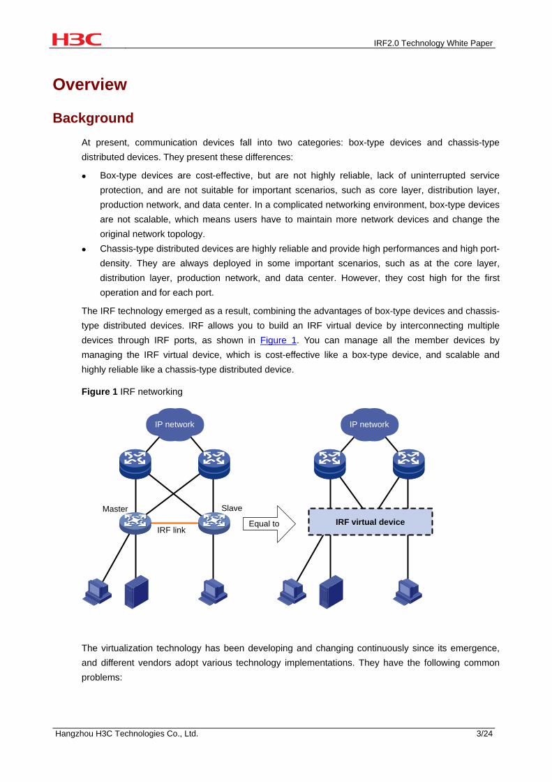
Figure 15 illustrates how IRF processes multicasts. Upon receiving a multicast, Slave 1 searches its multicast forwarding table, and finds that both Master and Slave 3 have connected multicast group members, and the optimal path from Slave 1 to Slave 3 is through Master. Therefore, Slave 1 forwards the multicast to Master, which makes three copies of the multicast, where two of them are forwarded to the multicast group members connected to Master, and the other is forwarded to Slave 3, which then forwards the multicast to other multicast group members. Each member device only needs to replicate the multicast as needed, ensuring that only one copy of the packet is transmitted among the devices, which saves system resources and increases processing speed of multicasts.
IRF2.0 Technology White Paper
Hangzhou H3C Technologies Co., Ltd. 19/24
Figure 15 Multicast forwarding
Packets to be forwarded
IRF virtual device
Master Slave 1
Slave 2Slave 3
Technical Characteristics
Generic Logical Software Architecture The biggest difference between IRF and other virtualization technologies is that it is not specific to a certain type of product, but is a generic logical software architecture. With this software architecture, devices of the same type can be connected to form a single logical device as needed. For example, IRF can combine box-type devices or chassis-type distributed devices to ensure the consistency of the virtualization functions of different types of products.
In this software architecture, IRF is a relatively independent function. It affects part of the system, rather than the stability of the whole system.
Mature System Architecture Different from other virtualization technologies, IRF adopts a widely applied system architecture rather than a new architecture.
IRF adopts a generic distributed system architecture. At present, the distributed system architecture has been applied on multiple kinds of H3C devices. A mature architecture has many advantages over a brand-new architecture:
Stable system: Defects of the system developed based on a mature system architecture have been solved, while a brand-new system architecture is bound to bring some problems specific for this architecture.
Optimal performance to ensure stable, reliable and effective operation of an IRF virtual device.

IRF2.0 Technology White Paper
Hangzhou H3C Technologies Co., Ltd. 20/24
Streamlined Chassis-Type Distributed Device At present, there are few technologies that can build a logical device by connecting chassis-type distributed devices. Even if some technologies can, the logical device established has limited functions, and supports a few number of devices. For example, some technologies can combine only two devices. In general design, distributed devices with multiple chassis adopt two-level management. The first level is distribution of chassis, and the second level is distribution of cards on a chassis. Although only one level of switching architecture is added to the present distributed multi-level switching architecture, the implementation complexity increases greatly. Therefore, this scheme delivers high complexity, low performance, low reliability, and is not applicable.
IRF solved this problem by combining multiple chassis-type distributed devices to form one logical chassis-type distributed device with one AMB, multiple SMBs, and multiple interface cards. The only difference between this logical chassis-type distributed device and a common chassis-type distributed device is the number of SMBs and interface card. This logical device has the same architecture as a common chassis-type distributed device. Therefore, the number of member devices does not depend on the system architecture any more, but depends on the hardware capability.
Rich and Stable Function Support IRF supports IPv4, IPv6, MPLS, security features, Open Application Architecture (OAA) cards, and high availability technologies, and ensures that these functions are effective and stable.
Other virtualization technologies adopt a brand-new system architecture, and technologies well applied on other devices need to be supported by each device in a virtual device. For example, the high availability technology commonly supported on chassis-type distributed devices is not supported on many virtualization technologies, and many functions of the high availability are lost. Based on its generic software architecture, IRF is an enhancement to the original system functions, without modifying the interfaces and operating mechanism of the original system. Therefore, an IRF virtual device can inherit the functions supported by the original system, ensuring the continuity of the technology and richness of the system functions. Users do not need to know whether different functions are supported by the IRF virtual device, and how the functions work.
Effective 1:N Backup Common chassis-type distributed devices adopt 1:1 backup, while IRF adopts 1:N backup, which enhances system reliability because multiple SMBs are available.
Generally, 1:N backup consumes great bandwidth, and consumes more bandwidth with the increase of the value of N. Other virtualization technologies solve the problem in two ways: reduce the supported high availability functions, and apply the limited resources to key services; or only back up the manually configured data, and increase service interruption time to reduce the quantity of synchronized data. However, these two methods do not really solve the problem.
IRF solved the problem of O(N) complexity of backed up data by using a multicast group, implementing O(1) algorithm, so that the system resources occupied by multiple SMBs are fixed, and will not change with the increase of the number of SMBs. Therefore, IRF delivers not only high reliability of 1:N backup but also high performance of 1:1 backup.

IRF2.0 Technology White Paper
Hangzhou H3C Technologies Co., Ltd. 21/24
Redundancy Protection on a Single Chassis-Type Distributed Device
The IRF technology delivers the 1:N redundancy function, and a chassis-type distributed device also has the 1:1 dual-main board redundancy function. When combining chassis-type distributed devices, other virtualization technologies make use of only the redundancy function of the virtualization technology while give up the backup function of the chassis-type distributed devices. When a main board on one device fails, the services on each card on the device where the main board resides are interrupted although the virtual device can operate. With the IRF technology, when a main board fails, all the cards can operate normally because the redundancy function on the chassis-type distributed device is kept, thus increasing the system availability.
Flexible Device Connections Compared with common virtualization technologies, IRF provides more flexible connections. You do not need to connect devices with dedicated cables, and you can specify common Ethernet ports as IRF ports to connect devices. The specified IRF ports can be either electrical ports or optical ports. You can also use optical fibers to connect devices located far from each other to form an IRF virtual device, making IRF applicable to more networking environments (the requirements on IRF ports depend on the device model). This feature is IRF specific.
Application Scenarios
Increasing Port Number As shown in Figure 16, when the number of access users is increased, and the ports of the switch cannot satisfy users’ needs, you can add a switch in the original IRF virtual device to increase the number of ports.
Figure 16 Diagram for increasing port number with IRF
Expanding System Processing Capability As shown in Figure 17, when the forwarding capability of the core switch cannot satisfy users’ needs, you can add a switch to form an IRF virtual device with the original core switch. If the forwarding capability of one switch is 64 Mpps, the forwarding capability of the whole IRF virtual device is 128

IRF2.0 Technology White Paper
Hangzhou H3C Technologies Co., Ltd. 22/24
Mpps after another switch is added. Note that this increases the forwarding capability of the entire IRF virtual device, not a single switch.
Figure 17 Diagram for expanding system processing capability with IRF
Expanding Bandwidth As shown in Figure 18, you can increase the uplink bandwidth of the edge switch by adding another switch to form an IRF virtual device with the edge switch. You can configure multiple physical links of the member devices as an aggregation group to increase bandwidth of the link to the core switch. To the core switch, the number of edge switches does not change. The original edge switch will back up the current configurations to the newly added switch in batches, which affects the network planning and configuration to the smallest extent.
Figure 18 Diagram for expanding bandwidth with IRF
IRF virtual device
IRF link
Connecting Devices Located Far from Each Other IRF connects devices located far from each other with optical fibers to form an IRF virtual device. As shown in Figure 19, users on each floor are connected to the external network through a wiring-closet switch. You can connect the wiring-closet switches to form an IRF virtual device. In this way, there is only one access device on each building, which simplifies the network structure. There are multiple

IRF2.0 Technology White Paper
Hangzhou H3C Technologies Co., Ltd. 23/24
links to the core network on each floor, which makes the network more robust and reliable. Configuration of the IRF virtual device rather than multiple wiring-closet switches reduces management and maintenance cost.
Figure 19 Diagram for connecting devices located far from each other with IRF
IRF linkSecond
floor
IRF link
Upstream aggregate link
Building A
Building B
First floor
Third floor
Second floor
First floor
Third floor
Upstream aggregate link
Core network
IRF virtual device
Simplifying Networking The following is a common networking, which uses MSTP and VRRP to support link backup and gateway backup. This networking is applicable to many environments, and distribution and access layer networking is taken as an example.
With IRF enabled, multiple devices on the distribution layer form an IRF virtual device, to which the accessing devices are connected. In this networking, MSTP and VRRP are not needed, simplifying network configuration. In addition, with the inter-device link aggregation function, when a member device fails, MSTP and VRRP convergence is no longer needed, thus increasing network reliability.

IRF2.0 Technology White Paper
Hangzhou H3C Technologies Co., Ltd. 24/24
Figure 20 Diagram for simplifying networking using IRF
Distribution layer
Access layer
IRF link
IRF virtual device
Distribution layer
Access layer
MSTP+VRRP MSTP+VRRP
Copyright ©2010 Hangzhou H3C Technologies Co., Ltd. All rights reserved.
No part of this manual may be reproduced or transmitted in any form or by any means without prior written consent of Hangzhou H3C
Technologies Co., Ltd.
The information in this document is subject to change without notice.