Embed Size (px)
Citation preview
HP ProLiant DL140 G2 Server - LED Indicators
In this document:
Status LED Indicators
Front Panel LED Indicators
Rear Panel LED Indicators
System Board LED Indicators
Status LED Indicators
This section contains illustrations and descriptions of the internal and external status LED indicators located on the:
Front panel
Rear panel
System board
These LED indicators aid in problem diagnosis by indicating the status of system components and operations of the server.
Front Panel LED Indicators
The set of status LED indicators on the front panel allows constant monitoring of basic system functions while the server is operating. These LEDs are mounted on the front panel board. Figure 1 and the table below show and describe the function of these LEDs.
Figure 1: Front panel LED indicators

Front Panel LED Indicators Status
Item Icon Component Status Description
1 UIDUID LED indicator (recessed underneath the UID button)
Blue A UID button has been pressed.
2 System health LED indicator
Off System health is normal.
Amber
A pre-failure system threshold has been breached. This may be any of the following:
o At least one fan failure (system fan or processor fan).
o At least one of the temperature sensors reached critical level (system or processor thermal sensors).
o At least one memory module failure.
A power supply unit error has occurred.
3Activity/link status LED indicators for NIC 1 and NIC 2
Solid green An active network link exists.
Flashing green
An ongoing network data activity exists.
Off The server is off-line.
4 HDD activity LED indicator
Flashing green Ongoing drive activity
Off No drive activity
5Power status LED indicator (recessed underneath the power button)
Green The server has AC power and is powered on.
Amber The server has AC power and is in standby mode.
Off The server is powered off (AC power disconnected).
Rear Panel LED Indicators

The set of status LED indicators located on the rear panel facilitates monitoring of network activity and aid in unit identification. Figure 2 and the table below show and describe the function of these LEDs.
Figure 2: Rear panel LED indicators
Rear Panel LED Indicators Status
Item Component Status Description
1 NIC activity/link status LED indicators
Solid green
An active network link exists.
Flashing green
An ongoing network data activity exists.
Off The server is off-line.
2 NIC network speed LED indicators
Steady amber
The LAN connection is using a GbE link.
Steady green
The LAN connection is using a 100 Mbps link.
Off The LAN connection is using a 10 Mbps link.
3 UID LED indicator (recessed beneath the UID button) Blue A UID button has been
pressed.
4 Link status LED indicator for the 10/100 Mbps LAN port
Green A network link exists.
Off No network link exists.
5 Activity status LED indicator for Flashing green
Network activity exists.

Rear Panel LED Indicators Status
Item Component Status Description
the 10/100 Mbps LAN port Off No network activity exists.
System Board LED Indicators
There are several internal LEDs located on the system board. Figure 3 and the table shown below describe the function of these LEDs.
Figure 3: System board LED indicators
System Board Power LED Indicators
Item Component Code Function Status Description
1 LED1 Rear UID LED indicator (recessed beneath the rear UID button, blue)
On A UID button has been pressed.
2 LED11 BMC heartbeat LED indicator On BMC is functional.
3 LED2 to LED5 LED7 to LED10
POST (Power-On Self Test) LED indicators (green)
On/Off Indicate the status of the ongoing POST routine.
© 2003 Hewlett-Packard Company · Privacy statement

HP ProLiant DL140 G2 Server - Troubleshooting the Server
In this document:
Diagnostic Tools
PhoenixBIOS Software
Power-On Self Test (POST)
POST Error Indicators
POST Beep Codes
POST-related Troubleshooting
Diagnostic LEDs
System board LEDs
Diagnostic Tools
This section gives an overview of the diagnostics tools supported by HP ProLiant DL140 Generation 2 server. It also describes the basic functions of the PhoenixBIOS Software.
Overview of Available Diagnostic Tools
The following utilities assist in diagnosing problems, testing hardware, and monitoring and managing server operations.
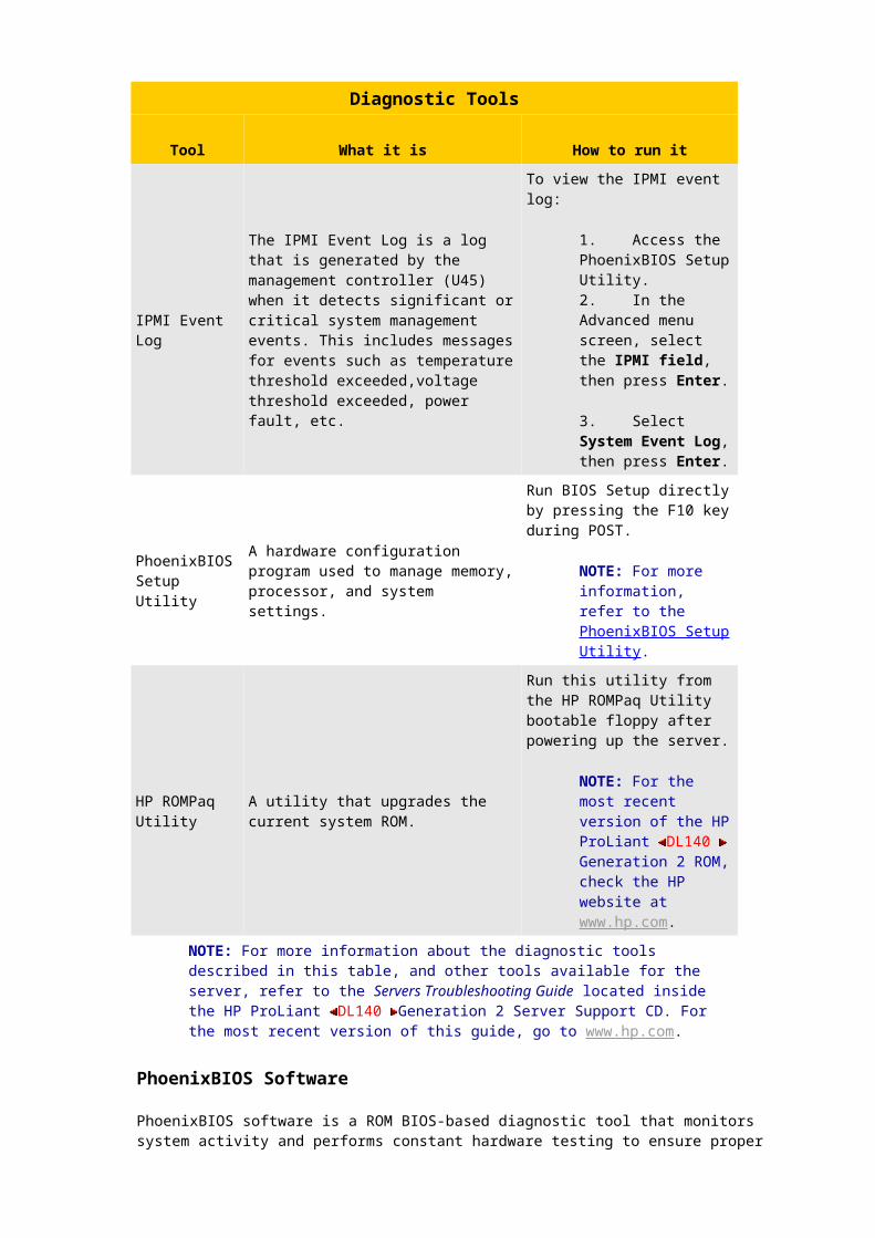
Diagnostic Tools
Tool What it is How to run it
User Diagnostics
A tool to assist testing and/or verifying operation of hardware. If problems are found, the diagnostics package isolates failures down to the replaceable part, whenever possible.
Diagnostics and utilities must be accessed when a system configuration error is detected during Power-On Self-Test (POST).
NOTE: Check the HP website at www.hp.com for the most recent version of the HP ProLiant DL140 Generation 2 User Diagnostics.
IPMI Event Log
The IPMI Event Log is a log that is generated by the management controller (U45) when it detects
To view the IPMI event log:
1. Access the PhoenixBIOS Setup

Diagnostic Tools
Tool What it is How to run it
significant or critical system management events. This includes messages for events such as temperature threshold exceeded,voltage threshold exceeded, power fault, etc.
Utility.2. In the Advanced menu screen, select the IPMI field, then press Enter.
3. Select System Event Log, then press Enter.
PhoenixBIOS Setup Utility
A hardware configuration program used to manage memory, processor, and system settings.
Run BIOS Setup directly by pressing the F10 key during POST.
NOTE: For more information, refer to the PhoenixBIOS Setup Utility.
HP ROMPaq Utility
A utility that upgrades the current system ROM.
Run this utility from the HP ROMPaq Utility bootable floppy after powering up the server.
NOTE: For the most recent version of the HP ProLiant DL140 Generation 2 ROM, check the HP website at www.hp.com.
NOTE: For more information about the diagnostic tools described in this table, and other tools available for the server, refer to the Servers Troubleshooting Guide located inside the HP ProLiant DL140 Generation 2 Server Support CD. For the most recent version of this guide, go to www.hp.com.
PhoenixBIOS Software
PhoenixBIOS software is a ROM BIOS-based diagnostic tool that monitors system activity and performs constant hardware testing to ensure proper system operation. ROM BIOS is a set of programs permanently stored in an EEPROM chipset (U54) located on the system board. These programs micro-manage the hardware devices installed on the computer.The PhoenixBIOS software serves three functions:
o Configure the system settings via the PhoenixBIOS Setup Utility.
Using the Setup program, installation, configuration, and optimization of the hardware devices on the system (clock, memory, disk drives, etc.) can be performed.
o Initialize hardware at boot via POST routines.
At power-on or reset, the software performs Power-On Self Test (POST) routines to test system resources and run the operating system.
o Perform run-time routines.
Using the software, perform basic hardware routines that can be called from DOS and Windows applications.
NOTE: For ease of reading, PhoenixBIOS Setup Utility will be simply referred to as Setup or Setup Utility in this guide.
NOTE: The screenshots used in this guide display default system values. These values may not be the same as those in the server.
PhoenixBIOS Setup Utility is a hardware configuration program built into the system's Basic Input/Output System (BIOS). Since most systems are already properly configured and optimized, there is normally no need to run this utility.This utility will need to be run under the following conditions:
o When changing the system configuration including: Setting the system time and date.
Configuring the hard drives.
Specifying the boot device sequence.
Configuring the power management modes.
Setting up system passwords or making other changes to the security setup.
o When a configuration error is detected by the system and if prompted (Run Setup message) to make changes to the BIOS settings.
NOTE: If the Run Setup messages repeatedly received, the battery located on the system board (BT1) may be defective. In this case, the system cannot retain configuration values in CMOS. Ask a qualified technician for assistance.
The Setup Utility loads the configuration values in a battery-backed nonvolatile memory called CMOS RAM. This memory area is not part of the system RAM, which allows configuration data to be retained when power is turned off. The values take effect when the system is booted. POST uses these values to configure the hardware. If the values and the actual hardware do not agree, POST generates an error message. This utility must be run to change the BIOS settings from the default or current configuration.
Accessing the Setup Utility
1. Turn on the monitor and the server.
If the server is already turned on, save the data and exit all open applications, then restart the server.
2. During POST, press F10.
If the F10key is not pressed before POST is completed, the server will have to be restarted again.
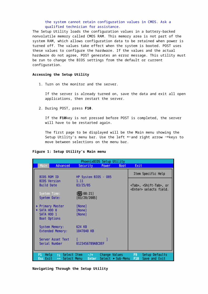
The first page to be displayed will be the Main menu showing the Setup Utility's menu bar. Use the left and right arrow keys to move between selections on the menu bar.
Figure 1: Setup Utility’s Main menu

Navigating Through the Setup Utility
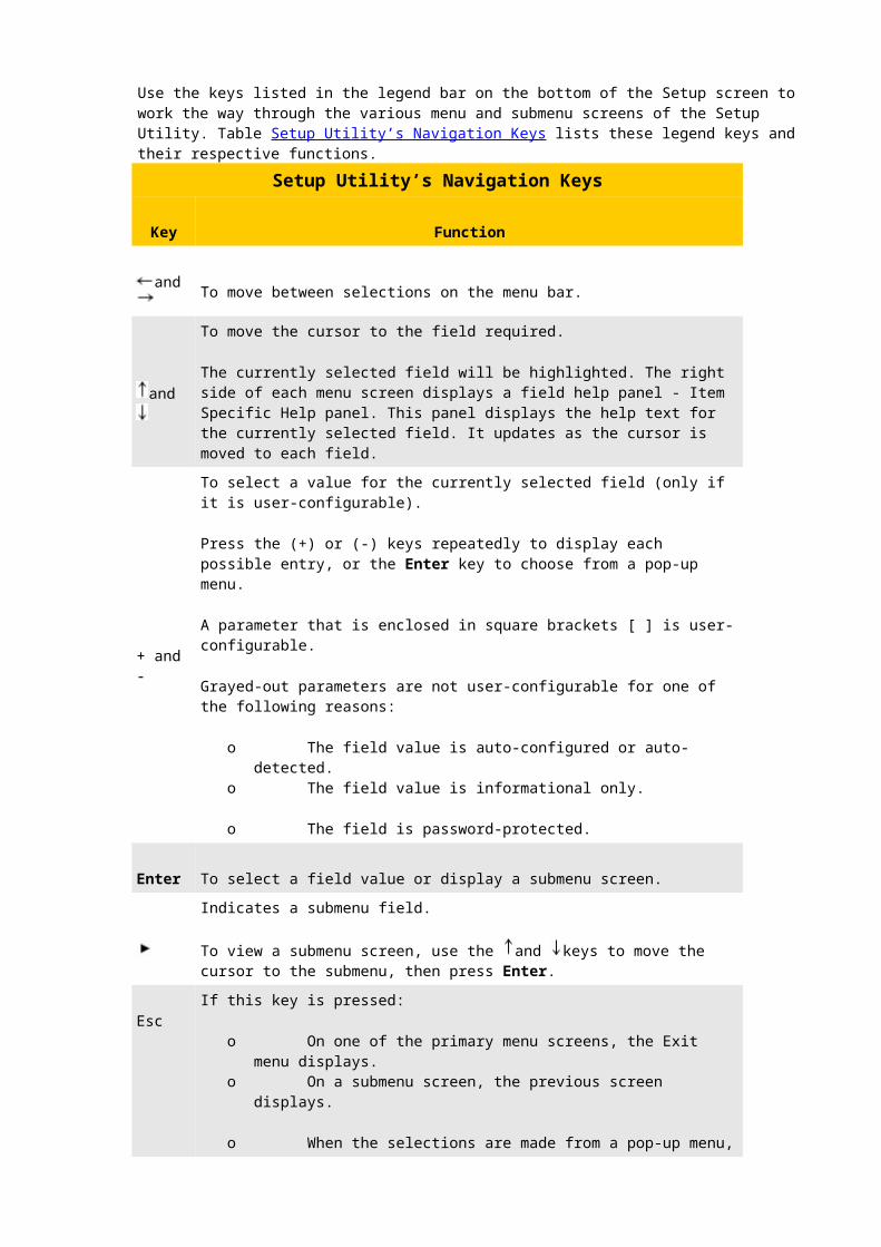
Use the keys listed in the legend bar on the bottom of the Setup screen to work the way through the various menu and submenu screens of the Setup Utility. Table Setup Utility’s Navigation Keys lists these legend keys and their respective functions.
Setup Utility’s Navigation Keys
Key Function
and To move between selections on the menu bar.
and
To move the cursor to the field required.
The currently selected field will be highlighted. The right side of each menu screen displays a field help panel - Item Specific Help panel. This panel displays the help text for the currently selected field. It updates as the cursor is moved to each field.
+ and - To select a value for the currently selected field (only if it is user-configurable).
Press the (+) or (-) keys repeatedly to display each possible entry, or the Enter key to choose from a pop-up menu.
A parameter that is enclosed in square brackets [ ] is user-configurable.
Grayed-out parameters are not user-configurable for one of the following reasons:
o The field value is auto-configured or auto-detected.o The field value is informational only.
Setup Utility’s Navigation Keys
Key Function
o The field is password-protected.
Enter To select a field value or display a submenu screen.Indicates a submenu field.
To view a submenu screen, use the and keys to move the cursor to the submenu, then press Enter.
Esc
If this key is pressed:
o On one of the primary menu screens, the Exit menu displays.o On a submenu screen, the previous screen displays.
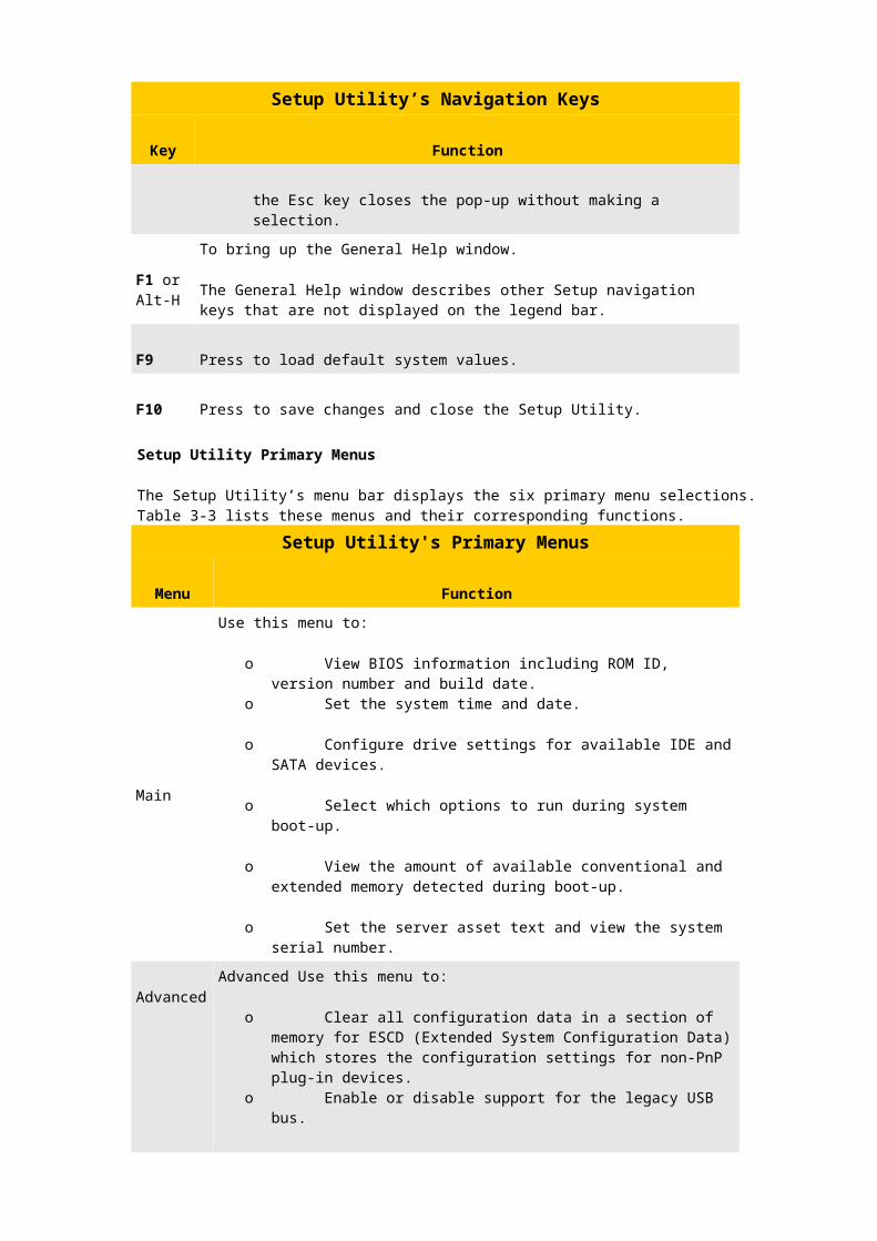
o When the selections are made from a pop-up menu, the Esc key closes the pop-up without making a selection.
F1 or Alt-H
To bring up the General Help window.
The General Help window describes other Setup navigation keys that are not displayed on the legend bar.
F9 Press to load default system values.
F10 Press to save changes and close the Setup Utility.
Setup Utility Primary Menus
The Setup Utility’s menu bar displays the six primary menu selections. Table 3-3 lists these menus and their corresponding functions.
Setup Utility's Primary Menus
Menu Function
Main
Use this menu to:
o View BIOS information including ROM ID, version number and build date.
o Set the system time and date.
o Configure drive settings for available IDE and SATA devices.
o Select which options to run during system boot-up.
o View the amount of available conventional and extended memory detected during boot-up.
o Set the server asset text and view the system serial number.
AdvancedAdvanced Use this menu to:
Setup Utility's Primary Menus
Menu Function
o Clear all configuration data in a section of memory for ESCD (Extended System Configuration Data) which stores the configuration settings for non-PnP plug-in devices.
o Enable or disable support for the legacy USB bus.
o Enable or disable RAID (Redundant Array of Inexpensive Disks) function for SATA devices.
o Select which LAN port will be used for IPMI-related functions.
o By default, the system uses the 10/100 Mbps LAN port (LAN1).
o View the MAC (Media Access Control) address of each of the three LAN ports.
o Configure settings for available PCI devices, as well as other PCI-related options.
o Enable or disable the USB host controller.
o Enable or disable the processor’s Hyper-Threading function.
o Hyper-Threading (HT) is an Intel technology that enables a processor to execute two threads in parallel—allowing the system to multi-task more effectively thus significantly boosts computing performance.
o Configure settings for the serial port.
o Configure console redirection settings to allow the system to be displayed on a remote terminal for online server management.
o Enable or disable the DIMM slots.
o View the specification version for the IPMI and BMC firmware.
o Configure LAN-related settings.
o Enable or disable the hardware watchdog timer.
o View real-time system temperature and voltage data.
CAUTION: Be cautious in setting field values in this menu as any incorrect value may cause the system to malfunction.NOTE: The SATA RAID option will be available in the future release of the PhoenixBIOS. Visit our HP website for updates on the BIOS with this feature enabled.
Security Use this menu to safeguard and protect the system from unauthorized use by setting up access passwords. For more
Setup Utility's Primary Menus
Menu Function
information on using this menu, go to the “System Passwords” section on page 3-9.
Power
Use this menu to:
o Enable or disable the power-saving options (they are NOS dependent).
o Enable or disable the modem ring power-up function.
o Enable or disable system wake-up at a preset time.
o Enable or disable the WOL (Wake-On-LAN) function of the onboard LAN controllers (U127 and U129).
o Set the mode of operation if a power loss occurs.
Boot
Use this menu to set the preferred drive sequence in which the Setup Utility attempts to boot the operating system.
By default, the server searches for boot devices in the following order:
1. IDE CD-ROM drive.2. Removable device.
3. Hard disk drive.
4. PXE (Preboot Execution Environment, remote boot).
Exit
Use this menu to select an exit option to quit from the Setup Utility. Options include:
o Exit Saving Changes - Saves changes made and close the Setup Utility.
Keyboard shortcut: F10.
o Exit Discarding Changes - Discards changes made and close the Setup Utility.
o Load Setup Defaults - Loads the factory-default settings for all Setup parameters.
Keyboard shortcut: F9
o Discard Changes - Discards all changes made to the Setup Utility and loads previous configuration settings.
o Save Changes - Saves all changes made to the Setup Utility.
NOTE: A USB CD-ROM drive connected to the server will not be considered a bootable device. It will not be displayed in the Boot menu.
Boot-time Diagnostic Screen

The boot-time diagnostic screen displays basic and important information about the current server configuration and is necessary for troubleshooting and may be required when asking for technical support. These information include:
o Processor specifications.o System BIOS version and release date.
o BMC firmware version.
o Size of the system and video memory, as well as the memory size allotted for the cache RAM and option ROM.
o Status of the wake-on LAN function.
o Serial port IO address.
o PS/2 mouse connection.
o Available SATA drives and PCI devices.
o MAC address of each of the three LAN ports.
o Server asset text and system serial number.
It is recommended to check this screen during the initial system setup and each time it is installed, removed, or if the accessories are upgraded.To view the boot-time diagnostic screen:The display of the diagnostic screen has to be enabled first during the bootup. Then perform the following steps:
1. In the Main menu screen, select Boot Options.2. Select the Boot-time Diagnostic Screen field.
3. Press the plus (+) or minus (-) key to set the field to Enabled.
4. Press F10 key to save the changes made and close the Setup Utility.
5. Reboot the server.
The diagnostic screen is displayed briefly at the end of POST.
Figure 2: Boot-time diagnostic screen

6. Press the Pause/Break key to continue displaying the screen until another key is pressed.7. Press any key to continue with the system bootup.
System Passwords
The Security menu to set system passwords that would provide different levels of protection for the server. There are three types of passwords that can be set:
o Supervisor password
Entering this password will allow the user to access and change all settings in the Setup Utility.
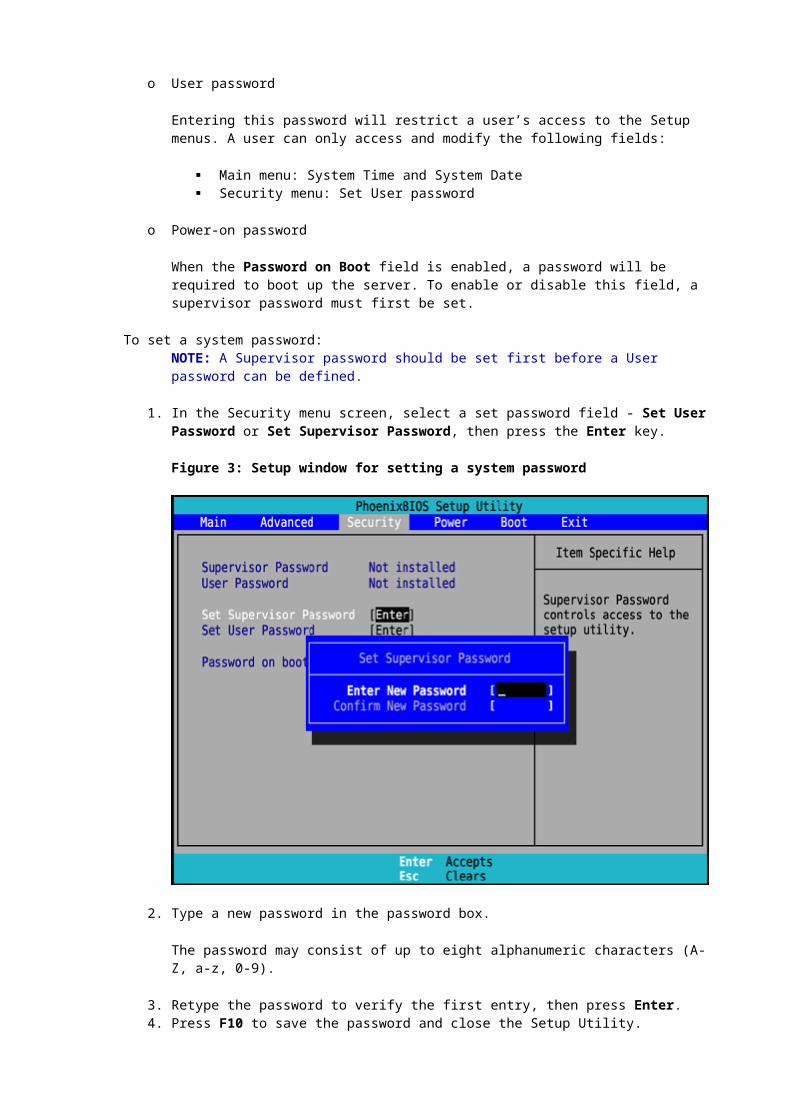
o User password
Entering this password will restrict a user’s access to the Setup menus. A user can only access and modify the following fields:
Main menu: System Time and System Date Security menu: Set User password
o Power-on password
When the Password on Boot field is enabled, a password will be required to boot up the server. To enable or disable this field, a supervisor password must first be set.
To set a system password:NOTE: A Supervisor password should be set first before a User password can be defined.
1. In the Security menu screen, select a set password field - Set User Password or Set Supervisor Password, then press the Enter key.
Figure 3: Setup window for setting a system password

2. Type a new password in the password box.
The password may consist of up to eight alphanumeric characters (A-Z, a-z, 0-9).
3. Retype the password to verify the first entry, then press Enter.4. Press F10 to save the password and close the Setup Utility.
After setting the password, Setup automatically sets the selected password field to Enabled.
To change a system password:
1. In the Security menu screen, select a set password field - Set User Password or Set Supervisor Password, then press Enter.
Figure 4: Setup window for changing a system password

2. Type the original password in the password box.3. Type a new password then press Enter.
4. Retype the new password to verify the first entry then press Enter again.
5. Press F10 to save the password and close the Setup Utility.
To remove a system password:
1. In the Security menu screen, select a set password field - Set User Password or Set Supervisor Password, then press Enter.
2. Type the original password then press Enter.
3. Press Enter twice without entering anything in the new and confirm password fields.
4. Press F10 to save the changes made and close the Setup Utility.
Setup automatically sets the selected password field to Clear.To reset a system password:If the user password or the supervisor password has been forgotten, the server will continue to function normally but it will not be possible to access the Setup Utility.If the Password on Boot field has been enabled and if both the user password and the supervisor password has been forgotten, the server cannot be rebooted .If the user password has been forgotten , the supervisor password can be used to reset it. However, if it is the supervisor password that is not remembered, the CMOS has to be cleared and the BIOS settings must be reset.
Recording Custom Setup Values
Write down the settings in the Setup Utility and keep them in a safe place. If the custom values ever need restoring (after a CMOS clear, for example), the Setup Utility must be run and these custom settings must be entered again. A record of these custom settings will make this much easier.
Loading System Defaults
If the system fails after the changes in the Setup menus are made, reboot the server, enter Setup and load the system default settings to correct the error. These default settings have been selected to optimize the server’s performance.To load the system defaults:
1. Reboot the server in a normal manner.2. During POST, press F10 to access the Setup Utility.
3. Press F9 to load the default values.
4. Press F10 to save the changes made and close the Setup Utility.
Clearing CMOS
The Setup configuration values (CMOS) may need to be cleared if the configuration has been corrupted, or if incorrect settings made in the Setup Utility have caused error messages to be unreadable. Clearing the CMOS data remove all system passwords.The clear CMOS switch is switch 2 of the system configuration switch (SW1). Refer to identifying system board components for the location of this switch.To clear CMOS:
1. Remove the top cover following the procedures described on Top Cover Removal.2. If necessary, remove any expansion boards, assemblies or cables that prevent access to the
system configuration switch.
3. Locate the system configuration switch (SW1) on the system board.
4. Identify SW1-2 of the switch.
By default, SW1-2 is set to the Off position.
5. Set SW1-2 to the On position.
This will clear the CMOS memory.
6. Switch SW1-2 back to its default Off position.7. Perform the post-installation procedures described on page 3-6.
8. During POST, press F10 to access the Setup Utility.
9. Press F9 to load the system default values.
10. Press F10 to save the changes made and close the Setup Utility.
Power-On Self Test (POST)
When the server boots up, a series of tests are displayed on the screen. This is referred to as Power–On Self–Test or POST. POST is a series of diagnostic tests that checks firmware and assemblies to ensure that the server is properly functioning. This diagnostic function automatically runs each time the server is powered on.
These diagnostics, which reside in the BIOS ROM, isolate server-related logic failures and indicate the board or component that needs to be replaced, as indicated by the error messages. Most server hardware failures will be accurately isolated during POST. The number of tests displayed depends on the configuration of the server.
POST Error Indicators

When POST detects a system failure, it either:
o Displays a POST error message, oro Emits a series of beep codes.
Recoverable POST ErrorsWhenever a non-fatal error occurs during POST, an error message describing the problem appears onscreen. These text messages are displayed in normal video (white text on black background). It shows the details of the error. The following is an example of a POST error message:Error message 1 of 1: Error code 0103Keyboard not detected - Keyboard errorIn some cases an error message may include recommendations for troubleshooting or require to press the Enter key to display recommendations. Follow the instructions on the screen.The table POST Error Messages lists down the most common POST error messages with their corresponding troubleshooting recommendation. It is recommended to correct the error before proceeding, even if the server appears to boot successfully.If the system displays one of the messages marked below with an asterisk (*), write down the code and message and contact the HP Customer Support provider.When no POST error message is displayed but the server stops during POST, listen for beep codes.
POST Error Messages
Error code Error message Description/corrective action
0200 Failure Fixed Disk
Fixed disk is not working or not configured properly.
1. Run Setup and check if the fixed-disk type is correctly identified.
2. Check to see if fixed disk is attached properly.
0210
Stuck key
Stuck key on keyboard.
3. Locate the stuck key on the keyboard and release it.
4. Reboot the server.
Mouse error
Mouse not working.
Verify the mouse cable is securely connected to the mouse port (not the keyboard port) on the rear panel of the server.
If the problem persists, replace the mouse or contact the HP Customer Support provider.
0211 Keyboard error
Keyboard not working.
Verify that the keyboard cable is securely connected to the keyboard port (not the mouse port) on the rear panel of the server.
If the problem persists, replace the keyboard or contact the HP Customer Support provider.
0212 Keyboard Controller Failed * Keyboard controller failed test.
POST Error Messages
Error code Error message Description/corrective action
0220 Monitor type does not match CMOS - Run SETUP
The attached monitor cannot be correctly identified in by Setup.
Run Setup and check if the monitor type is correctly identified.
0250 System battery is dead - Replace and run SETUP
The CMOS clock battery indicator shows the system battery is dead.
5. Replace the system battery following the procedures on page 3-43.
6. Run Setup to reconfigure the system.
0251 System CMOS checksum bad - Default configuration used
The settings in the Setup Utility have been corrupted or modified incorrectly, perhaps by an application program that changes data stored in CMOS.
Either of the operations given below can be performed:
o Load the system default values following the procedures.
o Access Setup and enter own customized values. If the error persists, check the system battery or contact the HP Customer Support provider.
0260 System timer error * The timer test failed. Requires repair of the system board.
0270 Real time clock error *
Real-Time Clock (RTC) fails BIOS hardware test. May require board repair.
0271 Check date and time settings
BIOS found date or time out of range and reset the RTC. May require setting legal date (1991-2099).
Access Setup and check the values in the System Time and System Date fields of the Main menu.
02D0 System cache error - Cache disabled * RAM cache failed and BIOS disabled the cache.
Invalid System Configuration Data Problem with the CMOS data.
Any of the following can be done:
o Load the system default values following the procedures.
o Access Setup and enter the own customized values.
o Clear the CMOS memory then restart the

POST Error Messages
Error code Error message Description/corrective action
server. For instructions, refer to the “Clearing CMOS” section on page 3-11. If the error persists, check the system battery or contact the HP Customer Support provider.
Operating system not found
Operating system cannot be located on any of the boot drives.
o Verify that the priority boot drive has power and that its IDE or SCSI cable is connected properly.
o Verify that the desired boot drive has power and its SCSI cable is connected.
o Verify that the IDE or SCSI cable is securely plugged into their respective system board connector.
o Verify that the boot device is enabled in the Setup Utility.
o Verify that the boot device has an operating system installed.
o If there is a diskette drive installed, verify that there is no non-bootable floppy present in it. If the problem persists, contact the HP Customer Support provider.
Terminal POST ErrorsThere are several POST routines that issue a POST terminal error and shut down the system if they fail. Before shutting down the system, the terminal-error handler issues a beep code signifying the test point error, writes the error to port 80h, attempts to initialize the video, and writes the error in the upper left corner of the screen (using both mono and color adapters).
POST Beep Codes
The POST routines cannot display messages when an error occurs if any of the following are present:
o The error occurs before the video display is initialized.o The video configuration fails, either there’s no graphics card installed or the one installed is
faulty.
o An external ROM module does not properly checksum to zero.
o The system memory cannot be initialized.
During these instances the server unit emits a buzzing sound followed by a series of audible beeps. An external ROM module (e.g. VGA) can also issue audible errors, usually consisting of one long tone followed by a series of short tones. If a blank screen is got on boot, but beeps are heard, count the beeps and refer to the following table for their corresponding meaning. If the beep code is missed perform the following steps:

1. Turn off the server by pressing the power button for five seconds or more.2. Restart the server by pressing the power button.
3. Listen for the signal again.
The routine derives the beep code from the test point error as follows:
1. The 8-bit error code is broken down to four 2-bit groups (Discard the most significant group if it is 00).
2. Each group is made one-based (1 through 4) by adding 1.
3. Short beeps are generated for the number in each group.
Example:
Test point 01Ah = 00 01 10 10 = 1-2-3-3 beepsTable POST Beep Codes lists the checkpoint codes written at the start of each test and the beep codes issued for terminal errors.
POST Beep Codes
Code Beep Description
02h Verify real mode
03h Disable non-maskable interrupts
04h Get processor type
06h Initialize system hardware
07h Disable shadow and execute code from the ROM
08h Initialize chipset with initial POST values
09h Set IN POST flag
0Ah Initialize processor registers
0Bh Enable processor cache
0Ch Initialize caches to initial POST values
0Eh Initialize I/O component
0Fh Initialize the local bus IDE
10h Initialize power management
11h Load alternate registers with initial POST values

POST Beep Codes
Code Beep Description
12h Restore processor control word during warm boot
13h Initialize PCI bus mastering devices
14h Initialize keyboard controller
16h 1-2-2-3 BIOS ROM checksum
17h Initialize cache before memory auto size
18h 8254 timer initialization
1Ah 8237 DMA controller initialization
1Ch Reset programmable interrupt controller
20h 1-3-1-1 Test DRAM refresh
22h 1-3-1-3 Test 8742 keyboard controller
24h Set ES segment register to 4 GB
28h Auto size DRAM
29h Initialize POST Memory Manager (PMM)
2Ah Clear 512 KB base RAM
2Ch 1-3-4-1 RAM failure on address line xxxx
2Eh 1-3-4-3 RAM failure on data bits xxxx of low byte of memory bus
2Fh Enable cache before system BIOS shadow
32h Test processor bus-clock frequency
33h Initialize Phoenix Dispatch Manager

POST Beep Codes
Code Beep Description
36h Warm start shut down
38h Shadow system BIOS ROM
3Ah Auto size cache
3Ch Advanced configuration of chipset registers
3Dh Load alternate registers with CMOS values
41h Initialize extended memory for ROM pilot
42h Initialize interrupt vectors
45h POST device initialization
46h 2-1-2-3 Check ROM copyright notice
47h Initialize I20 support
48h Check video configuration against CMOS
49h Initialize PCI bus and devices
4Ah Initialize all video adapters in system
4Bh Quiet boot start (optional)
4Ch Shadow video BIOS ROM
4Eh Display BIOS copyright notice
4Fh Initialize multi-boot 50h Display processor type and speed
51h Initialize EISA board
52h Test keyboard
54h Set key click if enabled

POST Beep Codes
Code Beep Description
55h Enable USB devices
58h 2-2-3-1 Test for unexpected interrupts
59h Initialize POST display service
5Ah Display prompt Press "F2 to enter SETUP”
5Bh Disable processor cache
5Ch Test RAM between 512 and 640 KB
60h Test extended memory
62h Test extended memory address lines
64h Jump to user patch 1
66h Configure advanced cache registers
67h Initialize multiprocessor APIC
68h Enable external and processor caches
69h Setup System Management Mode (SMM) area
6Ah Display external L2 cache size
6Bh Load custom defaults (optional)
6Ch Display shadow-area message
6Eh Display possible high address for UMB recovery
70h Display error messages
72h Check for configuration errors
76h Check for keyboard errors
7Ch Set up hardware interrupt vectors

POST Beep Codes
Code Beep Description
7Dh Initialize Intelligent System Monitoring (ISM)
7Eh Initialize coprocessor if present
80h Disable onboard super I/O ports and IRQs
81h Late POST device initialization
82h Detect and install external RS232 ports
83h Configure non-MCD IDE controllers
84h Detect and install external parallel ports
85h Initialize PC-compatible PnP ISA devices
86h Re-initialize onboard I/O ports.
87h Configure system board configurable devices (optional)
88h Initialize BIOS data area
89h Enable non-maskable interrupts
8Ah Initialize extended BIOS data area
8Bh Test and initialize PS/2 mouse
8Ch Initialize floppy controller
8Fh Determine number of ATA drives (optional)
90h Initialize hard-disk controllers
91h Initialize local-bus hard-disk controllers
92h Jump to user patch 2
93h Build MP table for multi-processor boards
95h Install CD-ROM for boot

POST Beep Codes
Code Beep Description
96h Clear huge ES segment register
97h Fix up MP table
98h 1-2 Search for option ROMs. One long, two short beeps on checksum failure
99h Check for SMART drive (optional)
9Ah Shadow option ROMs
9Ch Set up power management
9Dh Initialize security engine (optional)
9Eh Enable hardware interrupts
9Fh Determine number of ATA and SCSI drives
A0h Set time of day
A2h Check key lock
A4h Initialize typematic rate
A8h Erase F2 prompt
AAh Scan for F2 key stroke
ACh Enter Setup
AEh Clear boot flag B0h Check for errors
B1h Inform ROM pilot about the end of POST
B2h POST done, prepare to boot operating system
B4h 1 One short beep before boot
B5h Terminate quiet boot (optional)
B6h Check password (optional)

POST Beep Codes
Code Beep Description
B7h Initialize ACPI BIOS
B9h Prepare boot
BAh Initialize SMBIOS
BBh Initialize PnP option ROMs
BCh Clear parity checkers
BDh Display multiboot menu
BEh Clear screen (optional)
BFh Check virus and backup reminders
C0h Try to boot with INT 19
C1h Initialize POST Error Manager (PEM)
C2h Initialize error logging
C3h Initialize error display function
C4h Initialize system error handler
C5h PnP and dual CMOS (optional)
C6h Initialize note dock (optional)
C7h Initialize note dock late
C8h Force check (optional)
C9h Extended checksum (optional)
CAh Redirect Int
15h to enable remote keyboard
CBh Redirect Int 13h to memory technologies devices such as ROM, RAM, PCMCIA, and serial disk

POST Beep Codes
Code Beep Description
CCh Redirect Int 10h to enable remote serial video CDh Re-map I/O and memory for PCMCIA
CEh Initialize digitizer and display message
D2h Unknown interrupt
The following are for boot block in flash ROM.
E0h Initialize the chipset
E1h Initialize the bridge
E2h Initialize the processor
E3h Initialize system timer
E4h Initialize system I/O
E5h Check force recovery boot
E6h Checksum BIOS ROM
E7h Go to BIOS
E8h Set huge segment
E9h Initialize multiprocessor
EAh Initialize OEM special code
EBh Initialize PIC and DMA
ECh Initialize memory type
EDh Initialize memory size
EEh Shadow boot block
EFh System memory test
F0h Initialize interrupt vectors

POST Beep Codes
Code Beep Description
F1h Initialize runtime clock
F2h Initialize video
F3h Initialize System Management Manager (SSM)
F4h Output one beep
F5h Clear huge segment
F6h Boot to mini DOS
F7h Boot to full DOS
POST-related Troubleshooting
Perform the following procedures when POST fails to run or display error messages or emit beep codes.If the POST failure is during a routine bootup, check the following:
o All external cables and power cables should be firmly plugged in.o The power outlet to which the server is connected is working.
o The server and monitor are both turned on. The bicolor power status LED indicator on the front panel must be lit up green.
o The monitor's contrast and brightness settings are correct.
o All internal cables are properly connected and all boards firmly seated.
o The processor is fully seated in its socket on the system board.
o The heat sink is properly installed on top of the processor.
o Verify that the all memory modules are properly installed.
If the POST failure occurs after installing an accessory, check the following:
1. Remove the top cover according to the instructions described on Top Cover Removal .2. If necessary, remove any expansion boards, assemblies or cables that prevent access to the
system components.
3. Check the following:
If the PCI expansion board is installed, verify that the board is firmly seated in its slot and any switches or jumpers on the board are properly set.
NOTE: Refer to the documentation provided with the expansion board.

All internal cabling and connections are in their proper order. If the switches are changed on the system board, verify that each one is properly
set.
4. Perform the post-installation procedures.
5. Turn on the monitor.
6. If the server still does not work, repeat steps 1 and 2.
7. Remove all accessories, except the primary boot hard disk drive.
8. Repeat steps 4 and 5.
If the server now works, replace the boards and accessories one at a time to determine which one is causing the problem.
Diagnostic LEDs
The first diagnostic step should be to view the external system health indicators. If the DL140 G2 is one of many servers installed in a rack, the rear UID button should be pressed to make it easier to identify the server when the front of the rack is accessed.
After viewing the external LED indicators, remove the access panel and review the system board LEDs.
Figure 5: Diagnostic LEDs
Item Description
1 Location of LEDs on the front panel
2 HDD Drive Activity
3 NIC Activity/Link
4 System Health

Item Description
5 Unit Identifier
6 Power on Standby
Indicator Status Description
UID Blue The UID button was pressed.
System health
Off System health is normal.
Amber
A pre-failure system threshold has been breached. This may be any of the following:
At least one fan failure (system or processor fan)
At least one of the temperature sensors reached critical level (system or processor)
At least one memory module failure.
A power supply unit error has occurred.
NIC activity
Solid green Active network link
Flashing green Ongoing network data activity.
Off Server is off-line
HDD activity
Flashing green Ongoing drive activity
Off No drive activity
Power ON/Standby
Green Server has AC power and is powered on.
Amber Server has AC power and is in standby mode.
Off Server is powered off
System board LEDs
After the cause of the problem determined to be an internal component, remove the access panel and view the system board LEDs. There are three system board LEDs located as shown.

1 - LED1 - Rear UID.
2 - BMC Heartbeat.
3 - POST.
© 2003 Hewlett-Packard Company · Privacy statement