Embed Size (px)
Citation preview

10GbE Pass-Thru Module User Guide
Part Number 573130-002 December 2010 (Second Edition)

© Copyright 2009, 2010 Hewlett-Packard Development Company, L.P.
The information contained herein is subject to change without notice. The only warranties for HP products and services are set forth in the express warranty statements accompanying such products and services. Nothing herein should be construed as constituting an additional warranty. HP shall not be liable for technical or editorial errors or omissions contained herein.
Microsoft and Windows are U.S. registered trademarks of Microsoft Corporation. Bluetooth is a trademark owned by its proprietor and used by Hewlett-Packard Company under license.
Intended audience
This document is for the person who installs, administers, and troubleshoots HP BladeSystem c-Class products. Only persons experienced in server blade technology and configuration should attempt these procedures. HP assumes you are qualified in the servicing of computer equipment and trained in recognizing hazards in products with hazardous energy levels.

Contents 3
Contents
Introduction .................................................................................................................................. 5 Features ................................................................................................................................................... 5
Enterprise class performance ............................................................................................................. 5 Configuration and management ........................................................................................................ 5 Diagnostic tools ............................................................................................................................... 5
Pass-thru module architecture ...................................................................................................................... 5 Port mapping .................................................................................................................................. 6 Dual pass-thru modules ..................................................................................................................... 6 Redundant paths to server bays ......................................................................................................... 6
XModem .................................................................................................................................................. 6
Component identification ............................................................................................................... 7 10GbE Pass-Thru Module front panel ........................................................................................................... 7
Installing the pass-thru module ........................................................................................................ 9 Manually configuring the pass-thru module ................................................................................................... 9
Module security ............................................................................................................................... 9 Installing the module .................................................................................................................................. 9 Accessing the pass-thru module CLI ............................................................................................................ 10
Accessing the pass-thru module CLI remotely ..................................................................................... 10 Accessing the pass-thru module CLI locally ........................................................................................ 11 Production mode CLI ...................................................................................................................... 11 CLI menu ...................................................................................................................................... 11
Installing SFP+ transceivers ....................................................................................................................... 12
Replacing a pass-thru module ....................................................................................................... 13 Replacing an existing module ................................................................................................................... 13
Updating the 10GbE pass-thru firmware ........................................................................................ 14 Methods for updating the 10GbE Pass-Thru Module firmware ....................................................................... 14 Updating the firmware image using the Onboard Administrator CLI ............................................................... 14 Updating the firmware image using a USB key and the Onboard Administrator CLI ......................................... 17 Updating the 10GbE Pass-Thru Module firmware using the pass-thru serial port ............................................... 18
Performing a serial firmware image download .................................................................................. 18 Updating the firmware image using the serial port ............................................................................. 18
For more information ................................................................................................................... 20 Additional references ............................................................................................................................... 20
Troubleshooting .......................................................................................................................... 21 Health LED on the pass-thru module is not on .............................................................................................. 21 Health LED on the pass-thru module stays amber for more than 30 seconds and pass-thru module does not boot . 21 No link LED appears, even after you plug the cable into the SFP+ module ...................................................... 21 Cannot access the pass-thru module serial console interface using an RS232 connection from a PC Terminal Emulation Program .................................................................................................................................. 22 Error message appears on the serial console screen that the pass-thru module failed to complete the system self-test ............................................................................................................................................................. 22 The keyboard locks up when you use HyperTerminal to log in to the pass-thru module through the console interface ............................................................................................................................................................. 22

Contents 4
Cannot connect to the pass-thru module console interface remotely using Onboard Administrator ...................... 22 The download fails after starting to download the firmware file ..................................................................... 23 The pass-thru module configuration is corrupt .............................................................................................. 23 SFP+ transceiver port is disabled ............................................................................................................... 23
Technical specifications ............................................................................................................... 24 General specifications ............................................................................................................................. 24 Port names ............................................................................................................................................. 24 Physical and environmental specifications ................................................................................................... 25 Mini-USB to DB-9 serial adapter pin assignment .......................................................................................... 25
Regulatory compliance notices ..................................................................................................... 27 Class A equipment .................................................................................................................................. 27 Modifications .......................................................................................................................................... 27 Cables ................................................................................................................................................... 27 Canadian notice ..................................................................................................................................... 27 European Union regulatory notice ............................................................................................................. 27 Japanese class A notice ........................................................................................................................... 28 Korean class A notice .............................................................................................................................. 28 Laser compliance .................................................................................................................................... 28
Electrostatic discharge ................................................................................................................. 30 Preventing electrostatic discharge .............................................................................................................. 30 Grounding methods to prevent electrostatic discharge .................................................................................. 30
Acronyms and abbreviations ........................................................................................................ 31
Index ......................................................................................................................................... 33

Introduction 5
Introduction
Features The 10GbE Pass-Thru Module is designed for easy installation and high performance in an environment where network traffic and users increase continually.
Enterprise class performance The 10GbE Pass-Thru Module includes the following features:
• The unique ability to provide both 1 Gigabit and 10 Gigabit functionality on each port, enabling greater network flexibility
• Full support on the HP c-Class BladeSystem server blade enclosure and infrastructure compatible with any combination of HP c-Class BladeSystem server blades
• The ability to replace an existing 10GbE Pass-Thru Module without powering down the server blades or the enclosure
• Preconfiguration for immediate use with the HP c-Class BladeSystem Enclosure
• Robust configuration and management from the 10GbE Pass-Thru Module internal or external CLI
• Support for 10GbE Pass-Thru Module firmware upgrade using XModem functionality
Configuration and management The 10GbE Pass-Thru Module has the ability to enable or disable auto-negotiation on any port.
Diagnostic tools The 10GbE Pass-Thru Module includes the following hardware and firmware diagnostic tools:
• POST built into the pass-thru module boot process
• Pass-thru module LED panel displaying per port status and speed
• Health and UID status LEDs
• Reset switch and mini-USB to DB-9 RS232 management serial port (mini-USB to DB-9 RS232 cable sold separately)
• The ability to return the pass-thru module to known good condition in case of firmware corruption
Pass-thru module architecture The pass-thru module provides a 10GBASE-KR-to-SFI interface conversion, connecting through the enclosure backplane to 10GBASE-KR lanes from 16 server blades and brings out Small Form Factor Interface signals terminating in SFP/SFP+ transceiver connectors on the faceplate of the module.

Introduction 6
Port mapping For detailed port mapping information, see the HP BladeSystem Enclosure Quick Setup Guide or the HP BladeSystem Enclosure Setup and Installation Guide on the HP website (http://www.hp.com/go/bladesystem/documentation).
Dual pass-thru modules In a dual pass-thru module configuration, two pass-thru modules in the HP BladeSystem c7000 Enclosure provide redundant paths to the network ports on the server blades.
Redundant paths to server bays In a dual pass-thru module configuration, redundant Ethernet signals from each server blade are routed through the enclosure backplane to separate pass-thru modules within the enclosure. This configuration provides redundant paths to each server bay.
Redundant Ethernet signals from each blade server are routed through the enclosure backplane to separate pass-thru modules within the enclosure. However, port to server mapping varies based on the type of server blade installed.
XModem The pass-thru module supports XModem for transferring files during firmware upgrade using the serial management port. XModem sends blocks of data and includes an error-detection system called a checksum. When the data is received, the error detection system ensures that the entire message reached its destination. If not, the receiving computer sends a request for data retransmission.

Component identification 7
Component identification
10GbE Pass-Thru Module front panel
CAUTION: If you press the Reset button while the Health LED is green, the pass-thru module resets.
Item Description
1 UID LED • Blue light on—The pass-thru module is activated. • Blue light off—The pass-thru module is deactivated.
2 Health LED • Off—The pass-thru module is powered off. • Green—The pass-thru module is powered up, and all ports
match. • Amber—An issue exists, such as a port mismatch. For more
information, see the HP BladeSystem Enclosure Setup and Installation Guide.
3 Ethernet port • Green—Link is 10G. • Flashing green—10G link activity is detected. • Amber—Link is 1G. • Flashing amber—1G link activity is detected. • Flashing alternately green and amber—A link mismatch
condition exists. For more information, see the HP BladeSystem Enclosure Setup and Installation Guide.

Component identification 8
Item Description
4 Reset button
5 Mini-USB RS232 management serial port
6 Ports 1-16 SFP+ ports to support SFP and SFP+ transceiver modules and Direct Attach Cables (DAC).
Installing the pass-thru module 9
Installing the pass-thru module
Manually configuring the pass-thru module Configure the pass-thru module manually using a CLI. See "Accessing the pass-thru module ("Accessing the pass-thru module CLI" on page 10)" for more information.
Module security The 10GbE Pass-Thru Module does not provide network security. You must provide security for the module from somewhere else on the network.
Installing the module
CAUTION: Do not attach the pass-thru module cables until after configuration.
IMPORTANT: Make sure that the server NIC configuration matches the pass-thru module bay selected.
1. If a blank is installed in the bay, open the handle (1) and pull the blank out of the bay (2).
2. Open the handle on the pass-thru module.
3. Insert the pass-thru module into the bay (1).

Installing the pass-thru module 10
4. Close the handle (2).
Complete installation is indicated by a green Health LED. If the Health LED is amber or power is not applied to the module, see the HP BladeSystem Enclosure Setup and Installation Guide for troubleshooting information.
Accessing the pass-thru module CLI You can access the pass-thru module CLI remotely using the Onboard Administrator enclosure or locally using the mini-USB to DB-9 RS232 Management serial port.
Accessing the pass-thru module CLI remotely 1. Access the Onboard Administrator command line using telnet, SSH, or a serial connection. For more
information on how to access the Onboard Administrator CLI, see the HP BladeSystem Onboard Administrator User Guide.
2. Use the connect interconnect <bay> command to access the module. For example, if the module is located in bay 2, enter the connect interconnect 2 command.
To properly connect to the pass-thru module, you must disable flow control in the Onboard Administrator connect console.
To disable flow control after you have connected to the module:
1. Press Enter.
2. Press Ctrl + _ (Ctrl + Shift + underscore) to access the Connect Utility menu.
3. Enter C to change the port settings.
4. Enter R to change settings for the remote port.
5. Enter N to disable flow control.
After you have exited the menu, the pass-thru module CLI appears.
NOTE: If the pass-thru module CLI does not appear, press Enter.

Installing the pass-thru module 11
Accessing the pass-thru module CLI locally 1. Using a null-modem mini-USB to DB-9 RS232 serial cable (not included), connect the pass-thru
module management port to a local client device (such as a laptop computer).
2. Open a terminal emulation session and set the following parameters:
Parameter Value
Baud rate 9600
Data bits 8
Parity None
Stop bits 1
Flow control None
Production mode CLI The CLI provides backward and forward cursor control, backward deletion capability, and a 16-line history buffer. There is no tab "auto-completion" feature, but if there is enough information to determine the command to be used, the interface will accept part of the CLI command. For example, entering sys is enough to enter the system menu.
CLI menu
Command Result
Main menu
system Displays System menu.
port Displays Port menu.
System menu
info Displays system information.
config Enables you to set active or factory default configuration.
dumpconfig Dumps active configuration.
reset Resets pass-thru module.
Port menu
auto Displays Port menu auto-negotiation configuration details.
info Displays port information.
Global command
save Saves configuration.
Notes:
• The port/auto command uses the following format: "/port/auto <uplink|downlink> <port #> <on/off>". The port number can be a sequence of numbers (e.g., "1 3 5 15") or, if all ports are to be configured, the "*" option can be used (for example, "/port/auto uplink * off" disables auto-negotiation on all uplink ports).
• The port/info command displays link configuration and status.

Installing the pass-thru module 12
• The system/info command displays image version, board revision, or chip revisions.
• The effect from any CLI command is immediate. For example, configuring auto-negotiation on a port takes effect when the command is completed.
• Flow control is not configurable because the pass-thru module cannot handle or generate pause packets. When using the 10GbE Pass-Thru Module, you must ensure that your pause configuration is correct for both link partners.
Installing SFP+ transceivers
CAUTION: Disconnect all cables before removing or installing an SFP+ transceiver, because of the potential damage to the cables, the cable connector, or the optical interfaces in the SFP+ transceiver. Removing and installing an SFP+ transceiver can shorten the life of the product. Do not remove and insert SFP+ transceivers more often than is necessary.
CAUTION: HP recommends attaching an ESD-preventative wrist strap to your wrist and to a bare metal surface on the chassis to prevent electrostatic discharge.
CAUTION: When not using the fiber-optic SFP+ transceiver and cable, be sure to install the dust plugs on both. The plugs and caps protect the SFP+ transceiver ports and cables from contamination and ambient light.
1. Remove the dust plug and save for future use.
IMPORTANT: Use only HP-approved SFP+ transceivers.
2. Insert the SFP+ transceiver. With latch closed, be sure that the transceiver is fully seated and secure.
CAUTION: If you plan to install the SFP+ transceiver into the bottom row of the module, before installation, rotate the SFP+ transceiver 180 degrees from the position shown in the illustration.
Replacing a pass-thru module 13
Replacing a pass-thru module
Replacing an existing module
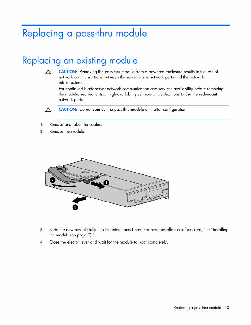
CAUTION: Removing the pass-thru module from a powered enclosure results in the loss of network communications between the server blade network ports and the network infrastructure. For continued blade-server network communication and services availability before removing the module, redirect critical high-availability services or applications to use the redundant network ports.
CAUTION: Do not connect the pass-thru module until after configuration.
1. Remove and label the cables.
2. Remove the module.
3. Slide the new module fully into the interconnect bay. For more installation information, see "Installing
the module (on page 9)."
4. Close the ejector lever and wait for the module to boot completely.

Updating the 10GbE pass-thru firmware 14
Updating the 10GbE pass-thru firmware
Methods for updating the 10GbE Pass-Thru Module firmware
CAUTION: The pass-thru module automatically reboots after the firmware update, which disrupts all server traffic on all ports on this pass-thru module. The server blades can be powered on while this pass-thru module firmware is updated, but they lose connectivity while the firmware reboots on each pass-thru module.
CAUTION: Do not power off the pass-thru module during the download process. Doing so will require you to power cycle the pass-thru module. Power cycling requires a successful image download before the pass-thru module is operable.
The 10GbE Pass-Thru Module firmware can be updated using the following methods:
• Onboard Administrator CLI
o Remotely through the management network
o Locally using a PC connected to the Onboard Administrator DB9 serial port
o Locally through a VGA and keyboard connected to the Onboard Administrator Enclosure KVM CLI console, if you are using an HP BladeSystem c7000 Onboard Administrator with KVM or the c3000 KVM option
NOTE: When using the Onboard Administrator for the firmware update, the pass-thru module firmware image must be available on an HTTP, FTP, or TFTP file, or located on a USB key drive accessible by the active Onboard Administrator.
• Locally using a PC connected to the pass-thru serial connector
NOTE: If you are using a local PC to update the firmware, the pass-thru module firmware image must be accessible from that PC.
NOTE: The pass-thru module boot code firmware image is usually named 10GPTHRU-w.x.y.z_FW.bin, where w.x.y.z is the firmware version number.
Updating the firmware image using the Onboard Administrator CLI
NOTE: The firmware update uses the Onboard Administrator Xmodem support with a firmware file hosted on an HTTP, FTP, or TFTP server. The firmware transfer can take up to seven minutes to complete.

Updating the 10GbE pass-thru firmware 15
NOTE: If you are using a USB key to transfer the firmware file, see "Updating the firmware image using a USB key and the Onboard Administrator CLI (on page 17)" for steps that must be completed before beginning this procedure.
1. Access the Onboard Administrator CLI remotely using Telnet or SSH, or locally using a serial connection to the active Onboard Administrator DB9 serial connector, or VGA and keyboard connected to the enclosure KVM ports. For more information on how to access the Onboard Administrator CLI, see the HP BladeSystem Onboard Administrator User Guide.
2. Log in to the active Onboard Administrator with a valid username and password that has a role on the Onboard Administrator allowing access to the pass-thru interconnect module.
NOTE: The pass-thru module in the examples below is located in interconnect bay 2. Wherever the 2 appears, substitute the number of the interconnect bay your pass-thru module is installed into.
3. At the Onboard Administrator prompt, enter connect interconnect 2. The following message appears: NOTICE: This pass-thru connection to the integrated I/O console is provided for convenience and does not supply additional access control. For security reasons, use the password features of the integrated switch. Connecting to integrated switch 2 at 9600,N81... Escape character is '<Ctrl>_' (Control + Shift + Underscore)
4. To display the pass-thru module console, press Enter.
5. Press Ctrl + Shift + _. The following message appears: Command: D)isconnect, C)hange settings, send B)reak, E)xit command mode X)modem send >
6. Enter C. The following message appears: Change settings for: L)ocal Session, R)emote Port [I/O Bay 2], E)xit
7. Enter R. The following message appears: Settings: B)audrate; flow control: N)one H)ardware S)oftware; E)xit >
8. Enter N. The following message appears: Connected to integrated switch 2 at 9600,N81. Escape character is '<Ctrl>_' (Control + Shift + Underscore)
9. At the 10GbE Pass-Thru # prompt, enter /system. The following message appears: [System Menu] info - System Information Display config - Set Active or Factory Default Config dumpconfig - Dump Saved Config xmodem - Download new image using XMODEM reset - Reset The Switch
10. At the System# prompt, enter xmodem. The following message appears: Confirm reset and start XMODEM download mode [y/n]:
11. Enter y. The following message appears: System Reset ... Ready to begin XMODEM file transfer. Hit return to continue.

Updating the 10GbE pass-thru firmware 16
12. Press the Enter key. The module console begins to print C characters until the Xmodem transfer begins.
13. Press Ctrl + Shift + _. The following message appears: Command: D)isconnect, C)hange settings, send B)reak, E)xit command mode X)modem send >
14. Enter x. The following message appears: Xmodem Send: Send a file to the interconnect module using the xmodem transfer protocol. The file can be downloaded to the OA from an HTTP(S), FTP, or TFTP server. After the file has been downloaded, the OA will transfer it to the switch. Please enter the URL below.
15. Enter the transfer URL (tftp://tftpServerIPAddress/10GPTHRU-1.0.7.0_FW.bin). The following message appears: Downloading file ... successful (transferred 210216 bytes) Continue with transfer (yes/no)?
16. Enter y. The following message appears: Starting transfer. Press '<Ctrl>_' (Control + Shift + Underscore) to cancel. Note: The transfer will terminate after 30 seconds of inactivity. ……….
The pass-thru module displays multiple lines of . characters until the entire firmware transfer is complete. The following message appears: Transfer complete.
Welcome to the HP 10GbE Pass-Thru Module Running image 1.0.7.0
Initializing ports................................
[10Gb Pass-Thru Menu] system - System Menu port - Port Menu global - Global Commands Menu
10Gb Pass-Thru# Port 1 is ENABLED Port 2 is ENABLED Port 3 is ENABLED Port 5 is ENABLED Port 6 is ENABLED Port 7 is ENABLED Port 8 is ENABLED Port 9 is ENABLED Port 10 is ENABLED Port 11 is ENABLED Port 12 is ENABLED

Updating the 10GbE pass-thru firmware 17
Port 13 is ENABLED Port 14 is ENABLED Port 15 is ENABLED Port 16 is ENABLED Port 1 Installed CU SFP Port 1 Approved CU SFP
NOTE: If the module console displays C characters instead of . characters, return to step 14 to restart the Xmodem transfer.
17. Press Ctrl + Shift + _. The following message appears: Command: D)isconnect, C)hange settings, send B)reak, E)xit command mode X)modem send >
18. Enter d.
19. To update the firmware on any other pass-thru modules installed in this enclosure, begin at step 4.
Updating the firmware image using a USB key and the Onboard Administrator CLI
NOTE: The firmware update uses the Onboard Administrator Xmodem support with a firmware file hosted on an HTTP, FTP, or TFTP server. The firmware transfer can take up to seven minutes to complete.
If no HTTP, FTP, or TFTP server is available, you can download the pass-thru module firmware file to a USB key which can then be inserted into the active Onboard Administrator USB port.
To update the image:
1. Copy the pass-thru module firmware file to the FAT32 formatted USB key in the \ directory.
2. Create a text file named text.cfg containing the following line: hello
3. Copy the text.cfg file to the USB key in the \ directory.
4. Insert the USB key into the active Onboard Administrator USB port.
5. Log in to the active Onboard Administrator CLI.
6. At the Onboard Administrator prompt, enter show usbkey. The following message appears: Configuration Script Files --------------------------------------- usb://d1/test.cfg
7. At the Onboard Administrator prompt, enter show oa network. The following message appears: Onboard Administrator #1 Network Information: Name: marketing3 DHCP: Disabled IP Address: 16.83.88.66 Netmask: 255.255.252.0 Gateway Address: 16.83.88.1 Primary DNS: 16.110.135.51

Updating the 10GbE pass-thru firmware 18
Secondary DNS: 16.110.135.52 MAC Address: F4:CE:46:86:FA:5D Link Settings: Auto-Negotiation, 100 Mbit, Full Duplex Link Status: Active Enclosure IP Mode: Disabled
8. To begin the firmware upgrade, begin at step 3 of "Updating the firmware image using the Onboard Administrator CLI (on page 14)" and continue following the instructions.
The pass-thru module firmware is available as a URL (http://OA_IP_Address/media/usbkey/d1/filename) at the active Onboard Administrator IP address with a path based on the d# command in the show usbkey response. In the URL, substitute the following:
o Replace OA_IP_Address with the actual Onboard Administrator IP address
o Replace d1 with the actual d#
o Replace filename with the pass-thru filename
Then, substitute the new URL in step 15.
Updating the 10GbE Pass-Thru Module firmware using the pass-thru serial port
NOTE: Downloading firmware through the pass-thru serial port is not the preferred method for upgrading a firmware image.
Performing a serial firmware image download If you are upgrading a pass-thru module directly from any existing operating system or boot code image, perform a serial download of the pass-thru module operating system firmware or boot code firmware.
This procedure requires:
• A computer running terminal emulation software
• 10GbE Pass-Thru Module operating system firmware or boot code images
Updating the firmware image using the serial port
CAUTION: The pass-thru module automatically reboots after the firmware update, which disrupts all server traffic on all ports on this pass-thru module. The server blades can be powered on while this pass-thru module firmware is updated, but they lose connectivity while the firmware reboots on each pass-thru module.
CAUTION: Do not power off the pass-thru module during the download process. Doing so will require you to power cycle the pass-thru module. Power cycling requires a successful image download before the pass-thru module is operable.

Updating the 10GbE pass-thru firmware 19
NOTE: The pass-thru module boot code firmware image is usually named 10GPTHRU-w.x.y.z_FW.bin, where w.x.y.z is the firmware version number.
1. Using the null modem mini-USB to DB-9 cable, connect the console port of the pass-thru module to the serial port of a computer that supports XModem/1K XModem.
2. Start HyperTerminal (part of Microsoft® Windows® operating system) or equivalent terminal emulation application (depending on the operating system), and set the parameters for terminal emulation console:
Parameter Value
Baud rate 9600
Data bits 8
Parity None
Stop bits 1
Flow control None
3. Power on or reboot the pass-thru module.
4. Hold down the Shift key and press the B key repeatedly during boot up, until the following message appears: "Ready to begin XMODEM file transfer. Press Enter to continue."
5. Repeatedly press the Enter key on the computer that is connected to the console port of the pass-thru module. When the console port is successfully communicating with the computer, indicating readiness for image transfer, continuous Cs appear.
6. Be sure that the new pass-thru module boot code firmware file is available on the computer. This file
can be downloaded from the HP website (http://www.hp.com/go/bladesystem/documentation).
7. Select <Transfer-Send File> from the menu, and choose the following options in the Send File window:
Filename: C:\#*!<unassigned_variable!*#
Protocol: 1K XMODEM
The Send File window displays the progress of the file transfer. The file transfer might take up to 7 minutes.
NOTE: Although slower, XModem also works if 1K XModem is not used.
After completing the transfer, the new image automatically boots.

For more information 20
For more information
Additional references Configure the 10GbE Pass-Thru Module after installation. Detailed information about how to configure the pass-thru module is available in 10GbE Pass-Thru Module Installation Instructions for HP BladeSystem c-Class Enclosures.

Troubleshooting 21
Troubleshooting
Health LED on the pass-thru module is not on
Cause Action
The pass-thru module is not seated properly. Be sure that the pass-thru module is inserted completely and seated properly.
The enclosure is not powered up. Be sure that the enclosure is powered up and all the power connections are intact.
An LED is faulty. Be sure that the pass-thru module is booted.
The pass-thru module is faulty. Send the module for repair.
Health LED on the pass-thru module stays amber for more than 30 seconds and pass-thru module does not boot
Cause Action
The Standby Mode Timeout function is malfunctioning.
Press the Reset button to force the pass-thru module to reboot.
No link LED appears, even after you plug the cable into the SFP+ module
Cause Action
The cable is not plugged in properly. Ensure that it is plugged in and seated properly at both ends.
The cable or connector heads are faulty. Replace the cable with another tested cable.
The SFP+ module on the pass-thru module or LED is faulty.
Examine and replace the cable. If no link LED displays, determine if the port is transferring data. • If yes, the LED is faulty. • If no, the SFP+ module might be faulty. Call a service
representative.
The pass-thru module uplink and downlink connections must be up before the LED illuminates.
The console displays messages if the uplink (SFP+ module) is working but the corresponding downlink cannot be established.

Troubleshooting 22
Cannot access the pass-thru module serial console interface using an RS232 connection from a PC Terminal Emulation Program
Cause Action
The mini-USB to DB-9 RS232 cable is faulty. Try another mini-USB to DB-9 RS232 cable.
The connection settings do not match the pass-thru module serial settings.
Be sure that the PC Terminal Emulation session settings match the pass-thru module serial settings.
Error message appears on the serial console screen that the pass-thru module failed to complete the system self-test
Cause Action
The system diagnostic tests failed. Note the reason for the failure and call a service representative.
The keyboard locks up when you use HyperTerminal to log in to the pass-thru module through the console interface
Cause Action
Scroll lock is on. Press the Scroll Lock key on the keyboard and be sure that the scroll lock is off.
Cannot connect to the pass-thru module console interface remotely using Onboard Administrator
Cause Action
Flow control is enabled. Disable flow control. Press Ctrl + Shift + _ to access the Connect menu. When in the menu, enter C to change settings, R for remote port settings, then N to disable flow control.

Troubleshooting 23
Cause Action
More than one person is connected to the module console from Onboard Administrator.
Use the Onboard Administrator CLI show interconnect sessions command to check for active sessions. If an interconnect session is active, use the clear interconnect session command to terminate active sessions on the module.
The download fails after starting to download the firmware file
Cause Action
The firmware file is not the correct file or is corrupt.
Obtain the latest firmware file that is specified for this pass-thru module. See "Downloading a remote firmware image upgrade" or "Downloading a serial firmware image upgrade" for more information.
The pass-thru module configuration is corrupt
Cause Action
An error was made when saving the pass-thru module configuration.
1 Reboot the pass-thru module and reload the factory settings. This action clears all settings and restores them to the initial values that were present when the pass-thru module was purchased.
2 After reloading the factory settings, reconfigure the pass-thru module settings.
SFP+ transceiver port is disabled
Cause Action
The SFP+ transceiver is not compatible with the pass-thru module.
Verify the SFP+ transceiver was purchased from HP. To purchase an SFP+ transceiver from HP, contact an authorized HP reseller.

Technical specifications 24
Technical specifications
General specifications
Category Specification
Auto-negotiation standard: ANSI/IEEE 802.3 Nway Auto-Negotiation
Protocols: CSMA/CD
Data transfer rates:
Gigabit Ethernet Full-Duplex: 2000 Mb/s
10Gb Ethernet Full-Duplex: 20000 Mb/s
Connectors:
10GbE Pass-Thru Module 16 SFP+ module connectors
10Gb multimode fiber optic cable
62.5/125 or 50/125 microns
10Gb singlemode fiber optic cable
9/25 micron
Number of ports per module: 16 x 10GbE/1000-Mb/s ports 1 x serial RS-232 mini-USB to DB-9 front panel management serial port
Port names
Port Link Ena Speed Neg Approved
1 Up/Downlink Dis/Ena 1Gb/10Gb On/Off Yes/No
2 Up/Downlink Dis/Ena 1Gb/10Gb On/Off Yes/No
3 Up/Downlink Dis/Ena 1Gb/10Gb On/Off Yes/No
4 Up/Downlink Dis/Ena 1Gb/10Gb On/Off Yes/No
5 Up/Downlink Dis/Ena 1Gb/10Gb On/Off Yes/No
6 Up/Downlink Dis/Ena 1Gb/10Gb On/Off Yes/No
7 Up/Downlink Dis/Ena 1Gb/10Gb On/Off Yes/No
8 Up/Downlink Dis/Ena 1Gb/10Gb On/Off Yes/No
9 Up/Downlink Dis/Ena 1Gb/10Gb On/Off Yes/No
10 Up/Downlink Dis/Ena 1Gb/10Gb On/Off Yes/No
11 Up/Downlink Dis/Ena 1Gb/10Gb On/Off Yes/No

Technical specifications 25
Port Link Ena Speed Neg Approved
12 Up/Downlink Dis/Ena 1Gb/10Gb On/Off Yes/No
13 Up/Downlink Dis/Ena 1Gb/10Gb On/Off Yes/No
14 Up/Downlink Dis/Ena 1Gb/10Gb On/Off Yes/No
15 Up/Downlink Dis/Ena 1Gb/10Gb On/Off Yes/No
16 Up/Downlink Dis/Ena 1Gb/10Gb On/Off Yes/No
Physical and environmental specifications
Category Specification
DC inputs 12 VDC: 6.25 A maximum per pass-thru module
Power consumption 75 W maximum per pass-thru module
Operating temperature
10° to 35° C (50° to 95° F)
Storage temperature -40° to 70° C (-40° to 158° F)
Operating humidity 5% to 95% RH noncondensing
Storage humidity 5% to 95% RH noncondensing
Pass-thru module dimensions
267.7 x 192.79 x 27.94 mm (10.5 x 7.5 x 1.1 in.)
Weight 1.7 Kg (3.7 lbs.)
Safety • TUV to UL 60950-1, and CAN/CSA C22.2 No. 60950-1 and to EN 60950-1
• CE Marking • RoHS 6/6 compliant
Mini-USB to DB-9 serial adapter pin assignment
From
Wire
To
Connector Contact Connector Contact
DSUB9F 2 Black Mini-USB 3
3 White 2
5 Green 5
1 DB-9 pins 1, 4, and 6 are connected. 4
6
7 DB-9 pins 7 and 8 are connected. 8

Technical specifications 26
From
Wire
To
Shell Braid Shell

Regulatory compliance notices 27
Regulatory compliance notices
Class A equipment This equipment has been tested and found to comply with the limits for a Class A digital device, pursuant to Part 15 of the FCC Rules. These limits are designed to provide reasonable protection against harmful interference when the equipment is operated in a commercial environment. This equipment generates, uses, and can radiate radio frequency energy and, if not installed and used in accordance with the instructions, may cause harmful interference to radio communications. Operation of this equipment in a residential area is likely to cause harmful interference, in which case the user will be required to correct the interference at personal expense.
Modifications The FCC requires the user to be notified that any changes or modifications made to this device that are not expressly approved by Hewlett-Packard Company may void the user’s authority to operate the equipment.
Cables Connections to this device must be made with shielded cables with metallic RFI/EMI connector hoods in order to maintain compliance with FCC Rules and Regulations.
Canadian notice This Class A digital apparatus meets all requirements of the Canadian Interference-Causing Equipment Regulations.
Cet appareil numérique de la classe A respecte toutes les exigences du Règlement sur le matériel brouilleur du Canada.
European Union regulatory notice Products bearing the CE marking comply with the following EU Directives:
• Low Voltage Directive 2006/95/EC
• EMC Directive 2004/108/EC
• Ecodesign Directive 2009/125/EC, where applicable
CE compliance of this product is valid if powered with the correct CE-marked AC adapter provided by HP.
Compliance with these directives implies conformity to applicable harmonized European standards (European Norms) that are listed in the EU Declaration of Conformity issued by HP for this product or

Regulatory compliance notices 28
product family and available (in English only) either within the product documentation or at the following HP website (http://www.hp.eu/certificates) (type the product number in the search field).
The compliance is indicated by one of the following conformity markings placed on the product:
For non-telecommunications products and for EU harmonized telecommunications products, such as Bluetooth® within power class below 10mW.
For EU non-harmonized telecommunications products (If applicable, a 4-digit notified body number is inserted between CE and !).
Please refer to the regulatory label provided on the product.
The point of contact for regulatory matters is Hewlett-Packard GmbH, Dept./MS: HQ-TRE, Herrenberger Strasse 140, 71034 Boeblingen, GERMANY.
Japanese class A notice
Korean class A notice
Laser compliance This product may be provided with an optical storage device (that is, CD or DVD drive) and/or fiber optic transceiver. Each of these devices contains a laser that is classified as a Class 1 Laser Product in accordance with US FDA regulations and the IEC 60825-1. The product does not emit hazardous laser radiation.
Each laser product complies with 21 CFR 1040.10 and 1040.11 except for deviations pursuant to Laser Notice No. 50, dated June 24, 2007; and with IEC 60825-1:2007.

Regulatory compliance notices 29
WARNING: Use of controls or adjustments or performance of procedures other than those specified herein or in the laser product's installation guide may result in hazardous radiation exposure. To reduce the risk of exposure to hazardous radiation: • Do not try to open the module enclosure. There are no user-serviceable components inside. • Do not operate controls, make adjustments, or perform procedures to the laser device other
than those specified herein. • Allow only HP Authorized Service technicians to repair the unit.
The Center for Devices and Radiological Health (CDRH) of the U.S. Food and Drug Administration implemented regulations for laser products on August 2, 1976. These regulations apply to laser products manufactured from August 1, 1976. Compliance is mandatory for products marketed in the United States.

Electrostatic discharge 30
Electrostatic discharge
Preventing electrostatic discharge To prevent damaging the system, be aware of the precautions you need to follow when setting up the system or handling parts. A discharge of static electricity from a finger or other conductor may damage system boards or other static-sensitive devices. This type of damage may reduce the life expectancy of the device.
To prevent electrostatic damage:
• Avoid hand contact by transporting and storing products in static-safe containers.
• Keep electrostatic-sensitive parts in their containers until they arrive at static-free workstations.
• Place parts on a grounded surface before removing them from their containers.
• Avoid touching pins, leads, or circuitry.
• Always be properly grounded when touching a static-sensitive component or assembly.
Grounding methods to prevent electrostatic discharge
Several methods are used for grounding. Use one or more of the following methods when handling or installing electrostatic-sensitive parts:
• Use a wrist strap connected by a ground cord to a grounded workstation or computer chassis. Wrist straps are flexible straps with a minimum of 1 megohm ±10 percent resistance in the ground cords. To provide proper ground, wear the strap snug against the skin.
• Use heel straps, toe straps, or boot straps at standing workstations. Wear the straps on both feet when standing on conductive floors or dissipating floor mats.
• Use conductive field service tools.
• Use a portable field service kit with a folding static-dissipating work mat.
If you do not have any of the suggested equipment for proper grounding, have an authorized reseller install the part.
For more information on static electricity or assistance with product installation, contact an authorized reseller.

Acronyms and abbreviations 31
Acronyms and abbreviations
CLI Command Line Interface
CPU central processing unit
CSMA/CD Carrier Sense Multiple Access with Collision Detection
DAC direct attach cable
FTP file transfer protocol
GMT Greenwich mean time
HTTP
hypertext transfer protocol
HTTPS hypertext transfer protocol secure sockets
I/O input/output
IEEE Institute of Electrical and Electronics Engineers
IP
Internet Protocol
KVM keyboard, video, and mouse

Acronyms and abbreviations 32
LAN local-area network
MAC
Media Access Control
NAS network access server
NIC network interface controller
OS operating system
POST Power-On Self Test
SFP small form-factor pluggable
SFP+ small form-factor pluggable - plus
SSH Secure Shell
TFTP Trivial File Transfer Protocol
USB universal serial bus
VGA video graphics array

Index 33
A
accessing the pass-thru module CLI 10, 11 accessing the pass-thru module, troubleshooting 22 additional references 20 architecture 5
B
boot code firmware image 14, 17, 18
C
Canadian notice 27 CLI (Command Line Interface) 11 CLI menu 11 CLI, commands 11 Command Line Interface (CLI) 11 components, front panel 7 components, identification 7 configuration and management 5, 9 configuration, troubleshooting 23 configuring the pass-thru module manually 9
D
default settings 24 diagnostic tools 5 downloading files 18, 23 dual pass-thru modules 6
E
electrostatic discharge 30 enterprise class performance 5 environmental specifications 25 European Union regulatory notice 27
F
features 5, 7 firmware, troubleshooting 23 firmware, upgrading 14, 17, 18 front panel components 7
G
general specifications 24 grounding methods 30
H
Health LED, troubleshooting 21 HyperTerminal, troubleshooting 22
I
identifying components 7 installing SFP+ transceivers 12 installing the pass-thru module 9 introduction 5
J
Japanese notice 28
K
Korean notices 28
L
laser compliance 28 link LED, troubleshooting 21
M
manually configuring the pass-thru module 9 methods for updating firmware 14 mini-USB to DB-9 serial adapter 25
O
Onboard Administrator, troubleshooting 22 operating system firmware 14, 17, 18
P
pass-thru module self-test, troubleshooting 22 pass-thru module, replacing 13 physical specifications 25 pin assignment 25
Index

Index 34
port mapping 6 port names 24
R
redundancy 6 regulatory compliance notices 27 replacing an existing pass-thru module 13 replacing the pass-thru module 13
S
security 9 self-test, troubleshooting 22 serial console interface, troubleshooting 22 serial download, performing 18 SFP+ transceiver, installing 12 SFP+ transceiver, troubleshooting 23 specifications, environmental 25 specifications, general 24 specifications, physical 25 specifications, technical 24
T
technical specifications 24 troubleshooting 21
U
updating the firmware 14, 17, 18 upgrading the pass-thru module 13, 14, 17, 18
X
XModem 6