Embed Size (px)
Citation preview
INV ITEDP A P E R
Fiber to the Home/Fiber to thePremises: What, Where,and When?The solution may be direct fiber to each home, or shared multiplexed fiber links,
or hybrid fiber-copper, -coax, or, perhaps, radio-over-fiber.
By Ton Koonen, Senior Member IEEE
ABSTRACT | After conquering the core and metropolitan
networks, fiber is now penetrating into the access domain. Its
low loss and huge bandwidth enable the delivery of any current
and foreseeable set of broadband services, and also make it a
nice match to the wireless link to the end user. Cost
effectiveness is a key issue, and will be decisive for the
network topology choices. Point-to-point may be the most
cost-effective for short-reach access, whereas point-to-multi-
point may be the most interesting at medium- to long-reach
access, or when line terminations in the local exchange become
a key issue. A number of optical techniques being deployed for
shared-fiber multiple access are discussed, based on time slot
multiplexing, frequency slot multiplexing, code division multi-
plexing, and wavelength multiplexing, including their applica-
tion in fiber to the home/fiber to the premises (FTTH/FTTP)
networks for fast data transfer (asynchronous transfer mode
(ATM) or Ethernet based) and for broadband service distribu-
tion (such as CATV). In the research laboratories, techniques
aiming at next-generation optical access are being studied,
such as wavelength routing for flexible capacity allocation and
easily adaptable hosting of services and service providers, and
radio-over-fiber techniques creating a powerful symbiosis of
the fiber world and the wireless world by enabling centralized
radio signal processing.
KEYWORDS | Broadband access; fiber to the home; multiple
access; passive optical networks; radio over fiber; wavelength
multiplexing
I . INTRODUCTION
The set of communication services being offered to
residential homes has seen rapid expansion in the last
decades. Customers are no longer only interested in voice
telephony, broadcast television, and radio; they are also
increasingly asking for always-on fast Internet communi-cation, video-based multimedia, fast peer-to-peer file
transfer, high definition multimedia on-line gaming, etc.
The growth of the population of elderly people is asking for
more medical care, and to prevent overload of hospitals
and health clinics, there is a trend to keep elderly people
longer in their home environment. For this, remote
observation by means of video surveillance and other
telemonitoring means generate additional communicationneeds. Other social trends such as teleworking in order
to reduce rush hour traffic are requiring higher capacity
to residential homes as well. The tailoring of services to
individual needs, and the emergence of several compet-
ing operators due to liberalization, are contributing to
the growth of access network traffic as well.
The conventional access network infrastructures,
namely the twisted-pair telephony networks and thecoaxial cable CATV networks, are having a hard time to
keep up with these traffic demands. Digital subscriber line
techniques (ADSL, VDSL, etc.) and cable modem
techniques are evolving into higher speeds, but at the
cost of a shorter reach. The unique properties of optical
single-mode fiber, being its low loss and extremely wide
inherent bandwidth, make it the ideal candidate to meet
the capacity challenges for now and the foreseeable fu-ture. Single-mode fiber has already been adopted as the
workhorse in core and metropolitan networks, and is
increasingly penetrating the access domain as well. Eco-
nomical considerations are key when decisions on fiber
introduction have to be made (see e.g., [1]). The costs of
Manuscript received March 31, 2005; revised September 9, 2005. This work was
supported in part by the European Commission and in part by the Dutch Ministry of
Economic Affairs.
The author is with the Communication Technologies: Basic Research and Applications
(COBRA) Institute, Eindhoven University of Technology, Eindhoven NL5600MB,
The Netherlands (e-mail: [email protected]).
Digital Object Identifier: 10.1109/JPROC.2006.873435
Vol. 94, No. 5, May 2006 | Proceedings of the IEEE 9110018-9219/$20.00 �2006 IEEE
digging and ducting are the major cost items in accessnetworks, outweighing by far the costs of the transmission
medium and the line terminating equipment. Civil works
typically may take some 85% of fiber to the home (FTTH)
first installed network costs, while the fiber cable and the
optical components take only 3%; the remainder is taken
by other hardware, installation activities, and other
services. Hence, in green-field situations, the costs of
introducing FTTH may not differ much from, e.g., twistedcopper pair or coaxial cable access solutions. Moreover,
the costs of fiber-optic line-terminating transceivers are
coming down rapidly. FTTH’s operational costs may be
lower, as it needs less active equipment in the field which
needs maintenance.
A fiber link can basically handle any kind of access
traffic, so installing fiber is an insurance for the future
(Bfuture-proof,[ or Bforecast-tolerant,[ investment).Hence, in many green-field situations, single-mode fiber
is being installed up to the home. For upgrading existing
copper networks, however, the situation is less clear. To
reap the maximum return on the investments made before
in these networks, much effort is spent in introducing
more advanced copper line techniques in the last link to
the end user. Also, fixed wireless access solutions bridging
wirelessly the gap to the end user are considered.However, the decreased reach of these solutions often
necessitates a further penetration of fiber in the access
feeder links, leading to hybrid fiber access networks with
decreasing length of copper lines to the homes, or to fiber-
fed wireless access. E.g., in fiber to the curb (FTTC)
networks, the fiber may run up to a street cabinet, from
where on an ADSL line on twisted copper pairs (or VDSL
line in shorter links) goes to the home. Or in hybrid fibercoax (HFC) networks fiber is running up to CATV street
cabinets, and from there coaxial cables run to the homes.
For short reach links, such as inside buildings,
multimode fiber may offer the advantage of easier handling
than single-mode fiber (in particular, in installation
activities such as splicing), due to its larger core diameter
(50 or 62.5 �m, versus some 9 �m) [2]. Its bandwidth-
times-length product is smaller than that of single-modefiber; however, this is not a significant issue in short-reach
links. Further gains in ease of handling may be obtained by
using multimode polymer optical fiber (POF), due to its
ductility and its even langer core sizes (beyond 100 �m).
This paper gives first an overview of basic fiber-optic
access network architectures, and discusses main basic
multiple access mechanisms: using time slots, electrical
frequency slots, wavelength slots, or code slots. Of these,time-slotted multiple access techniques will be treated in
more depth, covering ATM-, Ethernet- and gigabit-based
passive optical networks (ATM-PON, EPON, and GPON,
respectively). Next, frequency-slotted access such as
applied in hybrid fiber coax (HFC) networks will be
addressed. Subsequently, next to the static wavelength-
slotted WDM-PON, attention will be paid to access
techniques that are mostly still under research for next-generation access networks: wavelength-slotted access
with flexible wavelength routing for dynamic capacity
allocation, and radio-over-fiber techniques for fiber-
wireless networks. Finally, some speculative prospects
for the more distant future will be given.
II . FIBER ACCESS NETWORKARCHITECTURES
Basically, three architectures may be deployed for the fiber
access network (see Fig. 1).
1) Point-to-point architecture, where individual fibers
run from the local exchange to each home. Many
fibers are needed, which entails high first
installation costs, but also provides the ultimate
capacity and the most flexibility to upgradeservices for customers individually. In the local
exchange, as many fiber terminals are needed as
there are homes, so floor space and powering may
become issues.
2) Active star architecture, where a single fiber
carries all traffic to an active node close to the
end users, from where individual fibers run to
each cabinet/home/building. Only a single feederfiber is needed, and a number of short branching
fibers to the end users, which reduces costs; but
the active node needs powering and maintenance.
It also needs to withstand a wider range of
temperatures than in-door equipment. In network
upgrade scenarios, from the active node twisted
copper pair lines (such as for ADSL up to some
4 km at speeds up to some 6 Mbit/s, or VDSL atspeeds up to some 50 Mbit/s for lengths of some
500 m) may run, or coaxial cable lines (such as
for HFC), or even wireless links to the customer
[fixed wireless access (FWA)]. The active node
may be located in a cabinet at the street curb
site (fiber to the cabinet (FTTCab) or FTTC), or
in the basement of, e.g., a multidwelling units
building [fiber to the building (FTTB)] fromwhere the communication traffic is run through-
out the building by copper wired and wireless
local area networks at 100+ Mbit/s speeds.
3) Passive star architecture, in which the active node
of the active star topology is replaced by a passive
optical power splitter/combiner that feeds the
individual short branching fibers to the end users.
In addition to the reduced installation costs of asingle fiber feeder link, the completely passive
nature of the outside plant avoids the costs of
powering and maintaining active equipment in
the field. This topology has therefore become a
very popular one for introduction of optical fiber
into access networks, and is widely known as the
passive optical network (PON).
Koonen: Fiber to the Home/Fiber to the Premises: What, Where, and When?
912 Proceedings of the IEEE | Vol. 94, No. 5, May 2006
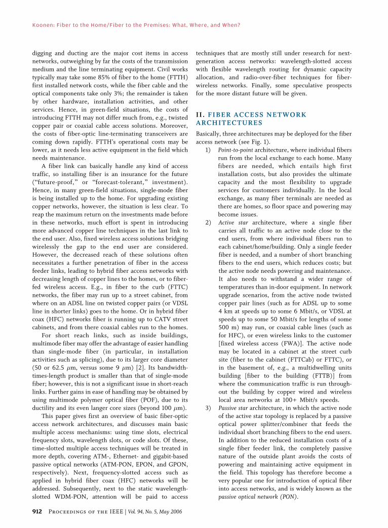
Besides technical performance, economic consider-
ations play a key role in deciding for a particular
architecture. The duct pattern may be the same for all
three architectures. However, in the point-to-point (P2P)
architecture many fibers need to be installed throughout
the network, whereas in the point-to-multipoint (P2MP)
architectures (active and passive star ones) in the feeder
part only one fiber is needed. The latter is advantageous aswell when a complete feeder duct is destroyed by, e.g., a
dragline machine: in the P2P architecture many fibers
have to be identified and correctly reconnected, whereas
in the P2MP architecture only a single fiber needs to be
repaired. In the P2P architecture, for each home two
optical line terminations are needed: one at the customer,
and one in the exchange. In the P2MP architecture, in the
exchange only a single termination is needed; however,
the line terminations will be more expensive than the ones
in the P2P architecture, as the sharing of the feeder fiber
requires extra measures for avoiding traffic collisions. On
the other hand, many customers share the costs of the line
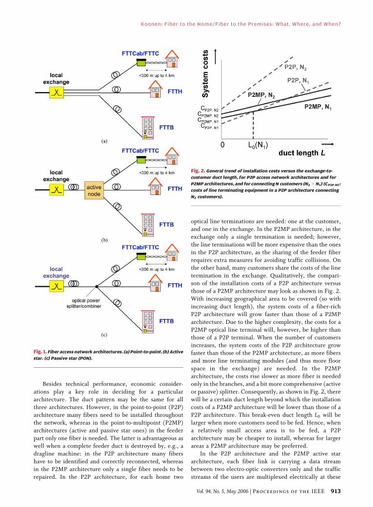
termination in the exchange. Qualitatively, the compari-son of the installation costs of a P2P architecture versus
those of a P2MP architecture may look as shown in Fig. 2.
With increasing geographical area to be covered (so with
increasing duct length), the system costs of a fiber-rich
P2P architecture will grow faster than those of a P2MP
architecture. Due to the higher complexity, the costs for a
P2MP optical line terminal will, however, be higher than
those of a P2P terminal. When the number of customersincreases, the system costs of the P2P architecture grow
faster than those of the P2MP architecture, as more fibers
and more line terminating modules (and thus more floor
space in the exchange) are needed. In the P2MP
architecture, the costs rise slower as more fiber is needed
only in the branches, and a bit more comprehensive (active
or passive) splitter. Consequently, as shown in Fig. 2, there
will be a certain duct length beyond which the installationcosts of a P2MP architecture will be lower than those of a
P2P architecture. This break-even duct length L0 will be
larger when more customers need to be fed. Hence, when
a relatively small access area is to be fed, a P2P
architecture may be cheaper to install, whereas for larger
areas a P2MP architecture may be preferred.
In the P2P architecture and the P2MP active star
architecture, each fiber link is carrying a data streambetween two electro-optic converters only and the traffic
streams of the users are multiplexed electrically at these
Fig. 2. General trend of installation costs versus the exchange-to-
customer duct length, for P2P access network architectures and for
P2MP architectures, and for connecting N customers (N2 9 N1) (CP2P;N2:
costs of line terminating equipment in a P2P architecture connecting
N2 customers).
Fig. 1. Fiber access network architectures. (a) Point-to-point. (b) Active
star. (c) Passive star (PON).
Koonen: Fiber to the Home/Fiber to the Premises: What, Where, and When?
Vol. 94, No. 5, May 2006 | Proceedings of the IEEE 913

terminals. Therefore, there is no risk of collision of opticaldata streams. These point-to-point links are straightfor-
ward and can basically be realized with simple and cheap
optical transceiver modules, which are readily available
commercially.
In the P2MP passive star topology (the PON), however,
the traffic multiplexing is done optically by merging the
data streams at the passive optical power combiner.
Collision of the individual data streams needs to beavoided by well-designed multiple access techniques. In
the following section, several of these techniques for a
PON will be discussed.
III . MULTIPLE ACCESS TECHNIQUESIN PON S
The common fiber feeder part of the PON is shared by all
the optical network units (ONU-s) terminating thebranching fibers. The traffic sent downstream from the
optical line terminal (OLT) at the local exchange is simply
broadcasted by means of the optical power splitter to every
ONU. With longer fiber feeder lengths and thus higher
feeder losses, the maximum possible split factor decreases.
Sending traffic from the ONU-s upstream to the local
exchange requires accurate multiple access techniques in
order to multiplex in a collision-free way the trafficstreams generated by the ONU-s onto the common feeder
fiber. Four major categories of multiple access techniques
for fiber access networks have been developed:
/ time division multiple access (TDMA);
/ subcarrier multiple access (SCMA);
/ wavelength division multiple access (WDMA);
/ optical code division multiple access (OCDMA).
A. TDMAIn a TDMA system, as shown in Fig. 3, the upstream
packets from the ONU-s are time-interleaved at the power
splitting point, which requires careful synchronizationof the packet transmission instants at the ONU-s. This
synchronization is achieved by means of grants sent from
the local exchange, which instruct the ONU when to
send a packet. The correct timing of these submissions is
achieved by ranging protocols, which sense the distance
from each ONU to the local exchange. In the OLT at the
local exchange, a burst mode receiver is needed which
can synchronize quickly to packets coming fromdifferent ONU-s, and which also can handle the different
amplitude levels of the packets due to differences in the
path loss experienced. As the ONUs are sharing jointly
the capacity of the OLT, the average capacity per ONU
decreases when the number of ONUs grows.
B. SCMAIn an SCMA system, illustrated in Fig. 4, the various
ONU-s modulate their packet streams on different
electrical carrier frequencies, which subsequently modu-
late the light intensity of their laser diode. The packetstreams are thus put into different frequency bands, which
are demultiplexed again at the local exchange. Each
frequency band constitutes an independent communica-
tion channel from an ONU to the OLT in the local
exchange, and thus may carry a signal in a format different
from that in an other channel (e.g., one channel may carry
a high-speed digital data signal, and an other one an analog
video signal). No time synchronization of the channels isneeded. The laser diodes at the ONU-s may have nominally
the same wavelength. When the wavelengths of the lasers
are very close to each other, the frequency difference
between them may result in beat noise products due to
optical beating at the photodetector in the receiver. These
noise products may interfere with the packet data
spectrum. The wavelengths of the laser diodes have to be
adjusted slightly different (e.g., by thermal tuning) inorder to avoid this optical beat noise interference.
Fig. 3. TDMA passive optical network.
Koonen: Fiber to the Home/Fiber to the Premises: What, Where, and When?
914 Proceedings of the IEEE | Vol. 94, No. 5, May 2006

C. WDMAIn a WDMA system (see Fig. 5, also known as WDM
PON), each ONU uses a different wavelength channel to
send its packets to the OLT in the local exchange. The
wavelength channels can be routed from the OLT to theappropriate ONU-s and backward by a wavelength
demultiplexing/multiplexing device located at the PON
splitting point. These wavelength channels constitute
independent communication channels and thus may carry
different signal formats; also no time synchronization
between the channels is needed. The same wavelength
channel may be used for upstream communication as well
as for downstream simultaneously, provided that reflec-tions in the link (which may occur at imperfect fiber
splices and connectors) are negligible. The isolation
requirements of the wavelength demultiplexer need to
be sufficiently high to suppress crosstalk, e.g., between two
different wavelength channels which are carrying high-
speed digital data and analog video signals, respectively.
The channel routing by the wavelength (de-)multiplexer
at the network splitting point prohibits broadcasting of
some channels to all ONU-s, as needed for instance for
CATV signal distribution.
For upstream communication, every ONU needs a
wavelength-specific laser diode, which increases costs,
and complicates maintenance and stock inventory issues.Alternatively, universal colorless ONU concepts may be
deployed which can benefit of economy of scale, and thus
lower costs. Such a concept may use a light source with a
broad spectrum at the ONU (e.g., a superluminescent
LED), of which the in-field multiplexer cuts out the
appropriate part of the spectrum. This Bspectral slicing[approach [3] reduces the inventory problems, but also
yields a reduced effective optical power available from theONU and thus limits the reach of the system. Another
colorless ONU concept is to use a reflective modulator at
the ONU, which modulates the upstream data on a
continuous light channel emitted at the appropriate
wavelength by the OLT and returns it to the OLT [4].
Thus, no light source is needed at the ONU, which eases
maintenance; but again the power budget is limited due
to Rayleigh backscattering and other reflections from
Fig. 4. SCMA passive optical network.
Fig. 5. WDMA passive optical network.
Koonen: Fiber to the Home/Fiber to the Premises: What, Where, and When?
Vol. 94, No. 5, May 2006 | Proceedings of the IEEE 915
connectors and splices in the fiber link. This limit may bealleviated by using a reflective semiconductor optical
amplifier (RSOA) of which the gain is modulated by the
upstream data; the amplifier noise may then become the
predominant limiting factor [5]. Alternatively, an injec-
tion-locked Fabry–Perot laser diode may be used [6].
D. OCDMAIn OCDMA, each ONU may use a specific optical code
word to distinguish itself from the others. Two versions
may be discerned: OCDMA using time-sliced code words,
and OCDMA using spectrum-sliced code words.
In a time-sliced OCDMA system, each ONU uses a
different signature sequence of short optical pulses, and
this sequence is on–off modulated with the data to be
transmitted. The duration of the sequence needs to be at
least equal to that of a data bit, and thus a very high-speedsignature sequence is needed to transmit moderate-speed
data. This limits the reach of the system due to the
increased impact of dispersion and the decreasing power
budget at high line rates. In the OLT at the local exchange,
the received signals are correlated with the known
signature sequences, in order to demultiplex the data
coming from the different ONU-s. As the signature codes
may be not perfectly orthogonal, some crosstalk may occur.In a spectrum-sliced OCDMA system, each ONU uses a
different combination of spectral slices from a broadband
optical source (such as an LED) of which the intensity is
modulated with the data to be transmitted. In the OLT, an
optical filter passing the same particular combination of
spectral slices can be used to distinguish the data from that
ONU. If the spectral slide codes are not perfectly
orthogonal, some crosstalk will occur.Two-dimensional coding by means of a combination of
time and spectral slicing can increase the addressable
number of ONUs [7].
E. Comparison of Multiple Access TechniquesTDMA systems have received the most attention for
broadband access networks, as they are most suited for
high-speed data transmission at relatively moderatecomplexity, and the required digital signal processing
can be readily and cost-effectively accommodated in
electronic integrated circuits. Two types of TDMA passive
optical networks have been addressed extensively in
standardization bodies: the ATM PON (APON) carrying
native ATM cells in the G.983 standard series of ITU-T
SG15, the Ethernet PON (EPON) carrying gigabit Ethernet
packets in IEEE 802.3, and recently the gigabit PON(GPON) able to carry ATM as well as Ethernet packets
with high line rates (up to 2.4 Gbit/s up- and downstream)
and high efficiency in the G.984 standard series. These
techniques will be discussed in more detail in Section IV.
Subcarrier multiplexing is particularly attractive for
downstream broadband broadcasting, such as in hybrid
fiber-coax (HFC) networks for distributing CATV services.
In an interactive all-fiber point-to-multipoint accessnetwork, SCMA broadband communication in the up-
stream direction uses individual separate frequency bands,
which puts high requirements on the frequency range and
linearity of the user equipment. In addition, precautions
have to be taken to avoid beat noise interference. Hence,
SCMA is not commonly deployed in interactive all-fiber
access networks. The application of subcarrier multi-
plexing techniques in hybrid fiber-coax CATV networkswill be discussed in more detail in Section V.
WDMA offers the most powerful solution for multiple
access, as it creates a virtual point-to-point topology on a
physical point-to-multipoint topology. Thus, in analogy
with point-to-point system concepts, this WDM-PON
concept brings the advantages of easy scaling toward
larger numbers of ONUs and of easy service upgrading per
individual customer. It is also the most costly solution dueto the additionally required wavelength-selective func-
tions. However, the costs of WDM components are coming
down, and the system concepts with colorless ONUs
improve the economics of WDM-PON further. Using
wavelength-based optical routing, flexible future-proof
access networks can be implemented. Remarkable effi-
ciency improvements of the system may be obtained when
the wavelength routing can be adjusted remotely by thenetwork operator, e.g., in order to reallocate capacity in
response to fluctuating traffic demands, or to dynamically
change service provisioning conditions in selected parts of
the network (for service upgrades, leasing parts of the
network, etc.). Dynamic WDMA thus is an attractive
solution for next-generation access networks, and is being
addressed in research. The static WDM-PON concept and
the dynamic one will be discussed further in Section VI.Time-sliced OCDMA puts high-speed requirements to
the electro-optical terminals, due to the line rate being a
multiple of the data rate. This leads to costly terminal
equipment, and hence has not become popular for fiber-
optic access networks. Spectrum-sliced OCDMA basically
offers a similar functionality as spectrum-sliced WDMA,
such as offering a parallel independent upstream path per
ONU without timing synchronization issues. The OLTfilter which implements the key of spectral slices in order
to discern a particular ONU may offer a means for
improved security. The broad spectrum, however, leads to
increased dispersion and thus the line rate achievable is
lower than that in a WDMA system.
IV. TDMA PON SYSTEMS
A. ATM PONThe full service access network (FSAN) group, a
committee of currently 21 major telecommunication
operators around the world, has been promoting the
ATM PON (also termed APON or BPON) for broadband
access networks since 1995.
Koonen: Fiber to the Home/Fiber to the Premises: What, Where, and When?
916 Proceedings of the IEEE | Vol. 94, No. 5, May 2006
1) ATM PON System Architecture: As laid down in the
G.983.1 Recommendation of ITU-T [8], an ATM PON
may have a downstream bitrate of 155 or 622 Mbit/s,
and an upstream one of 155 Mbit/s. The maximum
optical splitting ratio is 32 (may grow to 64), and the
maximum fiber length between the OLT in the local
exchange and an ONU is 20 km. The range in which this
length is allowed to vary is from 0 to 20 km. Standardsingle mode fiber (G.652) is foreseen. Widely spaced
wavelength multiplexing is used for separating the
bidirectional traffic: the downstream traffic is positioned
in the 1.5-�m wavelength band (allowing power boosting
by men, and the upstream traffic in the 1.3-�m band.
The 1.5-�m downstream band allows the use of erbium-
doped fiber amplifiers for power boosting and hence
improved link power budgets for broadcasting high-speeddownstream services (e.g., video). The 1.3-�m upstream
band allows the use of cheap uncooled Fabry–Perot laser
diodes in the ONU-s.
In the downstream direction of a 155-Mbit/s down/
155 Mbit/s up system, 54 ATM cells of 53 bytes each are
fitted together with 2 physical layer operation, adminis-
tration, and maintenance (PLOAM) cells of 53 bytes in a
frame [8]. The PLOAM cells contain each 53 upstreamgrants. A grant permits an ONU to send an ATM cell. By
sending these grants, the OLT controls at each ONU the
transmission of the upstream packets, and can therefore
assign dynamically a portion of the upstream bandwidth
to each ONU. In a 622 Mbit/s down/155 Mbit/s up
system, a frame contains four times as many cells (i.e.,
216 ATM cells and 8 PLOAM cells). The downstream
frame is broadcasted to all ONU-s. An ONU only extractsthose cells that are addressed to it.
In the upstream frame, both for the 155-Mbit/s
down/155-Mbit/s up system and for the 622-Mbit/s
down/155-Mbit/s up system, 53 ATM cells are fitted of
53 bytes each plus an overhead of 3 bytes per cell. This
overhead is used as guard time, as a delimiter and as
preamble for supporting the burst mode receiver process
in the local exchange.
The power budgets needed to bridge the fiber lossesand the splitter losses are denoted by three classes of
optical path losses: class A covering 5–20 dB of loss, class B
10–25 dB, and class C 15–30 dB. At the ONU, a launched
optical power of �4 to þ2 dBm is specified for class B, and
�2 to þ4 dBm for class C [9]. The ONU receiver
sensitivity at 155 Mbit/s should be better than �30 dBm
for class B, and �33 dBm for class C.
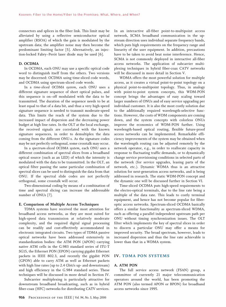
The ONU-s are usually positioned at different distancesfrom the local exchange. Therefore, the upstream trans-
mission of the packets from each ONU should be carefully
timed, in such a way that the packets do not collide at the
network splitter [8], [12]. The OLT has to measure the
distance to each ONU for this, and then instructs the ONU
to insert an equalizing transmission delay such that all
distances from the ONU-s to the OLT are equal to the
longest allowable distance (i.e., 20 km); see Fig. 6. Tomeasure the distance to each ONU, the OLT emits a
ranging grant to each ONU, and on receipt the ONU
returns a ranging cell to the OLT. In this distance ranging
process, the OLT can deduce the distance to each ONU
from the round trip delay.
Each ONU sends an upstream cell upon the receipt of a
grant. Because the path losses from each ONU to the OLT
may be different, the power of the cells received by theOLT may vary considerably from cell to cell. The burst
Fig. 6. Time ranging in a TDMA PON.
Koonen: Fiber to the Home/Fiber to the Premises: What, Where, and When?
Vol. 94, No. 5, May 2006 | Proceedings of the IEEE 917
mode receiver at the OLT should therefore have a wide
dynamic range, and should be able to set its decisionthreshold quickly to the appropriate level to discriminate
the logical ones from the zeros. Also the power of the ONU
transmitter can be varied over a certain range to limit the
requirements on the receiver dynamic range. In this
amplitude ranging process, the overhead to each ATM cell
is used for supporting the fast decision threshold setting at
the OLT burst mode receiver and the power adaptation at
the ONU burst mode transmitter.
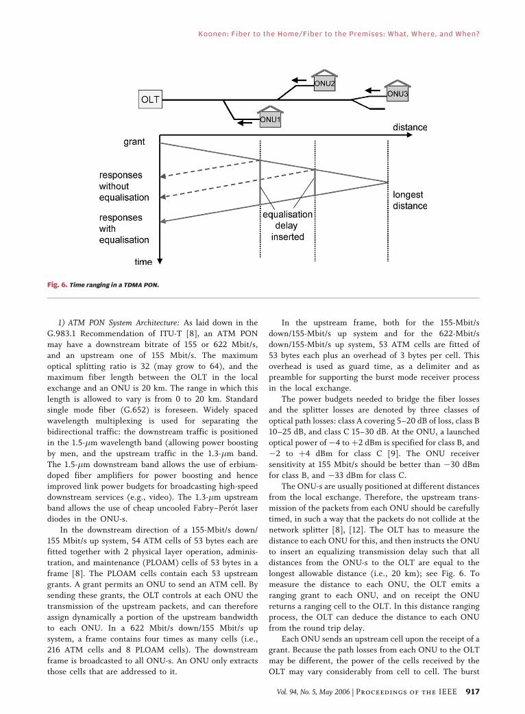
2) Network Protection: The long feeder line in a PON is
a vulnerable part of the network; when unprotected, a
break of it puts the whole PON out of service. Four types
of network protection have been described in ITU-T
Recommendation G.983.1 [9], as shown in Fig. 7. Type A
protection involves protection of the feeder fiber only by
a spare fiber over which the traffic can be rerouted bymeans of optical switches. After detection of a failure in
the primary fiber and switch-over to the spare fiber, also
reranging has to be done by the PON transmission con-
vergence (TC) layer. Thus, only limited protection of the
system is realized. Mechanical optical switches are usedup to now; when optical switching becomes cheaper, this
protection scheme may become more attractive. Type B
protection features duplication of both the feeder fiber
and the OLT. The secondary OLT is on cold standby, and
is activated when the primary one fails. Due to the high
sharing factor of the duplicated resources by the ONU-s,
this approach offers an economical yet limited protec-
tion. Type C protection implies full duplication of thePON, and all equipment is normally working which
allows fast switch-over (within 50 ms) from the primary
equipment to the secondary one. The branch fibers as
well as the ONU-s are protected; also a mix of protected
and unprotected ONU-s can be handled. Type D pro-
tection features independent duplication of the feeder
fibers and the branch fibers. It cannot offer fast res-
toration. It is less attractive than C, as it requires morecomponents but not a better functionality. In summary,
types B and C are the most attractive schemes for PON
protection.
Fig. 7. PON protection schemes.
Koonen: Fiber to the Home/Fiber to the Premises: What, Where, and When?
918 Proceedings of the IEEE | Vol. 94, No. 5, May 2006

3) Extensions of ATM PON: To further increase thespeeds laid down in Recommendation G.983.1, research
has been done into 622-, 1244-, and 2488-Mbit/s line
rates, both for upstream and downstream. A key technical
issue is the development of faster burst-mode circuitry to
adequately retrieve the timing and set the decision
threshold level, which becomes increasingly more difficult
at higher line rates. Operation of 1244-Mbit/s burst-mode
circuitry has been achieved [10]. In January 2003, ITU hasset standards for gigabit-capable PONs (G-PONs) in the
G.984 series, which may operate at downstream speeds
and upstream speeds up to 2.5 Gbit/s; see Section IV-C.
The G.983.1 ATM PON was initially mainly designed
for high-speed data communication. However, in the
residential access networks there is also a clear demand for
economical delivery of CATV services, for which subcarrier
multiplexing techniques are quite appropriate. In theenhanced Recommendation G.983.3 [9], room has been
allocated in the optical spectrum to host video services or
additional digital services next to the ATM PON services.
As shown in Fig. 8, the APON upstream services remain in
the 1260–1360 nm band (as in G.983.1), but the band for
downstream services is narrowed to 1480–1500 nm
(1480–1580 nm in G.983.1). Next to those, an enhance-
ment band for densely wavelength multiplexed bidirec-tional digital services (such as private wavelength services)
is foreseen, or an enhancement band for an overlay of video
delivery services. The latter is used in downstream
direction only, and coincides with the C-band as thus
economical erbium-doped fiber amplifiers can be deployed
for the power boosting required. When positioning an
overlay of CATV distributive services in the C-band,
stringent crosstalk requirements have to be put on the
wavelength multiplexers and demultiplexers, to preventnoticeable interference of the CATV signals into the digital
ATM signals, and vice versa [11].
In order to further improve the economics of ATM PON
systems, an extended PON system with an increase of the
network splitting factor to 128 and even 256 has been
developed, while still maintaining a passive outside plant
and compatibility with G.983.1 compliant ONU-s [12]. This
extended split is achieved by a larger optical power budget.In the downstream direction, at the OLT a high power laser
diode or an erbium-doped fiber amplifier (EDFA) is used to
boost the power. In the upstream direction, the sensitivity of
the burst-mode receiver is improved by applying an ava-
lanche photo diode (APD). Also 8 single-mode feeder fibers
(each feeding a 1 : 16 or 1 : 32 power splitter in the field)
are at the OLT coupled to a multimode fiber yielding a low-
loss coupling to the receiver.Even further extensions of the split factor and of the
reach of an ATM PON have been realized in the
SuperPON system [13]. An extension to a splitting factor
of 1 : 2048 has been achieved; this needs, however, active
equipment in the field. In the downstream direction
exploiting the 1530–1560 nm wavelength window, EDFA-s
are used for overcoming the large path losses. In the
upstream direction, gated semiconductor optical ampli-fiers (SOA-s) are deployed. Each SOA gate is opened when
upstream packets arrive, and is shut otherwise in order to
avoid funneling of the amplified spontaneous emission
noise toward the OLT. This SuperPON approach is not
compliant with current standards, and may be economi-
cally feasible only in the long term [12].
Recently, an other long-reach PON concept has been
demonstrated [14], having a reach up to 100 km and
Fig. 8. WDM enhancement G.983.3.
Koonen: Fiber to the Home/Fiber to the Premises: What, Where, and When?
Vol. 94, No. 5, May 2006 | Proceedings of the IEEE 919

addressing 500–1000 ONU-s with an aggregate symmet-
rical capacity of 2.5 or 10 Gbit/s using forward error
correction (FEC). Such a long reach and high split factor
would allow the bypassing of many local exchanges, thus
saving a lot on backhaul costs. EDFA-s (without gating) are
needed to overcome the splitting losses, and wavelength
multiplexing may be used for providing adequate capacityto network parts (Bwavelength to the street corner[).
B. Ethernet PONWith the rapid penetration of Ethernet-based services,
EPON techniques are receiving increasing attention, and
are promoted by the IEEE 802.3ah Ethernet in the First
Mile (EFM) Task Force [15]. The major difference withATM PON-s is that an EPON can carry variable-length
packets up to 1518 bytes in length, whereas an ATM PON
carries fixed-length 53-byte cells. This ability yields a
higher efficiency for handling IP traffic. The packets are
transported at the gigabit Ethernet 1.25-Gbit/s speed using
the IEEE 802.3 Ethernet protocol. A well-designed me-
dium access control (MAC) protocol is needed, a.o. for
bandwidth allocation and to support a variety of serviceshaving different quality-of-service requirements [16].
The EPON features full-duplex transmission similarly
as the ATM PON, with downstream traffic at 1490 or
1510 nm, and upstream traffic at around 1310 nm. As
shown in Fig. 9, standard IEEE 802.3 Ethernet packets
are broadcasted downstream by the OLT to all the ONU-s.
Each ONU inspects the headers, and extracts the packets
that are addressed to it. Several variable-length packetsare put into a fixed-length frame of typically 2 ms
duration, and each frame begins with a 1-byte synchro-
nization marker. In the upstream direction, also 2 ms
frames are used. A frame contains time slots that each are
assigned to one of the ONU-s (see Fig. 10). Each ONU
puts one or more of its upstream variable-length IEEE
802.3 packet into a time slot; if it has no packets to send,
the time slot may be filled with an idle signal. No packetfragmentation takes place. The time slot overhead
consists of a guard band and indicators for timing and
signal power. The OLT thus allows only one ONU to send
at a time, and no collisions occur. The time slot size
typically is 125 or 250 �s. The frame duration and time
slot size are not standardized by the IEEE 802.3ah EFM
Task Force. The values mentioned are typical examples;
they depend on quality-of-service requirements such aslatency and guaranteed bandwidth.
Fig. 9. Downstream traffic in an EPON.
Fig. 10. Upstream traffic in an EPON.
Koonen: Fiber to the Home/Fiber to the Premises: What, Where, and When?
920 Proceedings of the IEEE | Vol. 94, No. 5, May 2006

C. Gigabit PONIn order to extend the capacity of PONs into the Gbit/s
arena, the ITU has set standards for the GPON in the
G.984.x series. The GPON architecture, set in Recom-
mendation G.984.1, is much alike the ATM PON one:the maximum optical splitting ratio is 128, and the
maximum fiber reach from OLT to ONU is 20 km
whereas its minimum is zero. Protection schemes have
also been foreseen, similar to those shown in Fig. 7.
The GPON physical media dependent layer has been
set in G.984.2; it includes downstream line rates of
1244.16 or 2488.32 Mbit/s, in the wavelength range
1480–1500 nm. In upstream direction, line rates fore-seen are 155.52, 622.08, 1244.16, or 2488.32 Mbit/s, in
the wavelength range 1260–1360 nm.
In GPON Transmission Convergence Recommenda-
tion G.984.3, a framing format of 125-�s length is used
which can host a lot of different packetized traffic
formats. This GPON encapsulation method (GEM) may
host Ethernet packets, and/or native ATM packets, and/or
native TDM, as illustrated in Fig. 11 [17], [18]. Thus, aGPON system may operate in an Ethernet-packet-only
mode, or in an ATM-only mode, or in a mixed mode.
Ethernet frames may be fragmented among a number of
GEM cells, which is not possible in the native IEEE 802.3
technology. Hence, GPON using GEM can obtain a high
efficiency for transport of IP data payload, by utilizing up
to 95% of the available bandwidth in the transmission
channel.GPON also supports quality of service, as it enables
service level agreement (SLA) negotiations between the
OLT and the ONU through the ONU management and
configuration interface set in G.984.4.
D. Comparison of TDMA SystemsBy using ATM techniques, ATM PON offers built-in
quality of service for all traffic classes, whereas EPONthrough using native Ethernet may not, unless the QoS is
managed at the IP level. EPON in its basic form thus may
not support voice services with QoS as provided in the
traditional public switched telephone network (PSTN),
and also the support of real-time services still has issues
due to latency and packet jitter; advanced MAC protocols
may reduce these shortcomings. On the other hand, ATM
suffers from the cell tax (5-byte header per 53-byte cell),
and thus EPON is more efficient and simple for
transporting variable length IP packets. The recentlyintroduced GPON can carry ATM as well as Ethernet
traffic in any mixed mode, with high efficiency, and hence
may combine the quality-of-service advantages of ATM
nicely with the efficiency of Ethernet.
V. HYBRID FIBER COAX NETWORKS
CATV networks usually are laid out over large geo-graphical areas, and are mainly designed for downstream
broadcasting of analog TV channels (or digital TV
channels, multiples of which fit into one analog TV
channel frequency slot). These channels are frequency-
division multiplexed in a carrier frequency grid extending
up to 1 GHz. In traditional all-coax CATV networks, in the
trunk part amplifiers were typically required every 600 m,
and there were 20–40 amplifiers in cascade. Duringtransmission in the coaxial cable network, the signal
quality deteriorates due to the addition of noise from the
electrical amplifiers and intermodulation products caused
by their nonlinearities. In a hybrid fiber coax (HFC)
system, as shown in Fig. 12, low-loss fiber is used in the
trunk part, and the trunk amplifiers are eliminated [19].
This improves the signal quality, and reduces maintenance
costs. The CATV headend station is collecting the CATVsignals, remodulating them into a specific frequency grid,
and sending them via single-mode fibers to fiber nodes.
Each fiber node converts the composite optical signal into
an electrical one, which is carried via a coaxial cable
network including a few (typically four to six) RF am-
plifiers to the residential homes. A single headend may
thus serve hundred thousands of customers, and a fiber
node some thousands of customers.In the fiber part of the HFC network, the signals are
carried with subcarrier multiplexing; see Fig. 13. The TV
channels are each amplitude-modulated on a separate
frequency. After summing all these modulated signals, the
composite CATV signal is modulating the intensity of the
Fig. 11. GPON encapsulation method according to ITU-T Rec. G.984.3.
Koonen: Fiber to the Home/Fiber to the Premises: What, Where, and When?
Vol. 94, No. 5, May 2006 | Proceedings of the IEEE 921

light output of a highly linear high power laser diode (or
laser diode followed by a linearized external modulator).
At the receiver in the fiber node, the optical signal is
converted backward into the composite electrical CATV
signal by means of a highly linear PIN photodiode plus
subsequent electrical amplifying stages. Thereafter the
signal can be passed to the coaxial cable network. When
using a laser diode with low relative intensity noise and
high linearity (or a carefully linearized external modula-
tor), the CATV signal can be transported with very little
loss of quality. If a 1.5 �m wavelength laser diode is used,
erbium-doped fiber amplifiers may boost the power at the
headend and compensate for the splitting losses in the
fiber network; thus very extensive networks feeding
Fig. 12. Hybrid fiber coax network.
Fig. 13. Subcarrier multiplexing.
Koonen: Fiber to the Home/Fiber to the Premises: What, Where, and When?
922 Proceedings of the IEEE | Vol. 94, No. 5, May 2006

thousands of ONU-s can be realized. In this wavelengthregion, however, with direct laser modulation second
order intermodulation products may arise due to laser
chirp in combination with fiber chromatic dispersion.
With an external modulator, however, the chirp is small
enough to avoid these intermodulation products. When a
1.3-�m wavelength laser diode is used, the fiber chromatic
dispersion is sufficiently small to eliminate these products
as well; however, there do not exist such efficient opticalamplifiers for this wavelength region, and hence less ex-
tensive networks can be realized.
The CATV signal quality that can be maintained in
HFC networks is very high due to the fiber’s low losses
and high bandwidth in comparison with coaxial cable.
Therefore, in HFC networks fiber is gradually brought
deeper into the network, and fiber nodes have to serve
fewer customers through a coaxial cable network oflimited size (i.e., minifiber nodes, each serving in the
order of 40 customers).
HFC networks are nowadays not only carrying CATV
and FM radio broadcast services, but cable operators are
also exploiting them for voice telephony and data
transport using cable modems in a so-called triple-play
scenario. The associated upstream traffic is carried in
SCMA mode, and can deploy parts of the spectrumunused for CATV and FM radio broadcast. In Europe,
typically the 5–65 MHz band is used for this; in the
United States, the 5–42-MHz range. For downstream
data, e.g., the 300–450-MHz range is used, taking into
account that Internet traffic is usually highly asymmetric
(much more downloading of data than uploading).
Downstream per 8-MHz CATV channel, 30–50-Mbit/s
data can be accommodated deploying 64 or even 256quadrature amplitude modulation (QAM). For upstream
data transport, due to ingress noise less comprehensive
modulation schemes are to be used; e.g., DQPSK, which
offers about 3 Mbit/s per channel.
VI. DENSE WAVELENGTH MULTIPLEXINGIN ACCESS NETWORKS
The rapid growth in access network traffic asks for
powerful measures to increase the capacity of the
infrastructure. An installed fiber plant can effciently be
upgraded to higher capacities, while protecting the
infrastructure investments made, by introducing multiple
wavelength channels in the same fiber infrastructure. In
the static WDM-PON concept, discussed in Section III-C,
each ONU is connected by a specific wavelength pair tothe OLT in a point-to-point fashion. By assigning the
wavelengths dynamically to the ONUs, e.g., by flexible
wavelength routing, the access network capabilities can
be significantly enhanced [20]–[22]. This dynamic WDM-
PON concept has not reached commercial deployment
yet, but is a promising topic for research into future
access network techniques.
A. Role of Multiwavelength TechniquesBy creating multiple wavelengths in a common fiber
infrastructure, the capabilities of this infrastructure can be
extended into an additional dimension. This wavelength
dimension may implement independent communication
planes between nodes, thus enabling versatile inter-
connection patterns between nodes. E.g., these intercon-
nections can be asynchronous, can have different
quality-of-service requirements, and can transport sig-nals with widely differing characteristics. This has some
similarity with the enhanced interconnection possibili-
ties of multilayer printed circuit boards.
The role of this wavelength dimension can be manifold,
such as:
• to separate services;
• to separate service providers;
• to enable traffic rerouting;• to provide higher capacity;
• to serve more users (improved scalability).
Also the assignment of the wavelength channels may
follow different scenarios:
• static allocation;
• semistatic allocation;
• dynamic allocation.
Each of the above-mentioned roles may follow one ormore of the scenarios. In the following, each of the roles
will be considered in more detail.
1) Service Separation: By allocating a wavelength (or a
set of wavelengths) for a cohesive set of services, these
services may be separated by means of their wavelength.
This may be beneficial for treating a set of services with
similar quality-of-service requirements and signal char-acteristics in a dedicated way. E.g., bidirectional multime-
dia services may have specific requirements for latency and
bandwidth, and hosting these in one or more specific
wavelength channels with their dedicated routing patterns
may help for supporting these requirements. In a point-to-
multipoint architecture, by using wavelength routing a
lower split factor may be implemented for services with
high bandwidth requirements, whereas other services mayget higher split factors.
Separating services on a wavelength basis may also help
to realize different tariff structures by the network oper-
ator: traffic traveling on the first-priority (e.g., guaranteed
congestion-free) wavelength channel may be charged a
higher fee than on lower priority channels.
2) Service Provider Separation: Wavelength channels mayalso be dedicated to service providers. They thus get each
their virtually independent infrastructure, on which they
can guarantee their own basket of services and pertaining
quality of service. It also enables flexible leasing of
network capacity by the network operator, who may assign
a certain set of wavelength channels for a certain region for
a certain period to a specific service provider, and charge
Koonen: Fiber to the Home/Fiber to the Premises: What, Where, and When?
Vol. 94, No. 5, May 2006 | Proceedings of the IEEE 923

him for that. By rerouting the wavelength channels the
network operator can easily change these leasing condi-
tions. When a user subscribes to a particular service
provider, he may get the corresponding wavelength
channel(s) and thus transparently the services involved.
In case of several competing service providers in the
same region, these providers may thus coexist in the same
network infrastructure independently.
3) Traffic Rerouting: Using multiple wavelength chan-
nels serving different regions, each wavelength channel or
set of wavelength channels may feed a dedicated region.
Such a region may encompass one or more ONUs. For
instance, in a static WDM-PON, each ONU is connected to
the OLT by a specific pair of wavelengths. When operating
in networks with diversity in fiber links (e.g., in a meshnetwork in which various fiber paths can be followed to
establish a connection between two nodes), wavelength-
specific routing actually ties wavelengths to regions. By
changing the wavelength routing, this Bcoloring[ can
easily be changed. For instance, when a specific fiber link
feeding a region fails and the traffic carried through the
wavelength channels on it is disrupted, by steering the
wavelength channel(s) via alternative fiber paths the traf-fic provisioning to that region may be quickly restored.
Also when a link feeding a certain region gets con-
gested, and no extra wavelength channels can be added
on that link, these extra channels may be routed via
alternative fiber links to the same region, thus resolving
the congestion problem.
4) Higher Capacity: Adding wavelength channels on a
fiber link may also be done just to increase the capacity on
the link, by creating several channels in parallel carrying
the same type of traffic. This implies, for example, that
more of the same services may be offered. To get access to
those services, however, the end user needs to be retuned
to that wavelength channel.
B. Wavelength Channel Assignment ScenariosWavelength channels may be assigned to end users on
different time scales, depending on the service operator or
network operator requirements. Basically, this may be
seen as Bcoloring the network,[ on a slow or fast time
scale. Fig. 14 illustrates the principle: from the OLT-s in
the local exchange, multiple wavelength channels are fed
to the ONU-s in the regional user cells via a tree-and-
branch PON. By wavelength-selective routing in the PON,or wavelength selection at each ONU, each wavelength
channel can be assigned to one or more ONU-s. Thus,
capacity can be specifically shared between these ONU-s.
The ONU-s subsequently transfer these capacity shares to
the end users (possibly via an electrical last drop to the end
user, being wired or wireless).
The mapping of the network capacity resources to the
end users (or their local networks) can thus be changed bychanging the wavelength channel assignment. Basically
two approaches can be followed for this, as illustrated
in Fig. 15: wavelength selection at the ONU-s, or a
wavelength routing in the field.
In the wavelength selection approach shown in
Fig. 15(a), all wavelength channels are broadcasted to
every ONU, and subsequently the ONU is tuned to the
wavelength channel wanted. Clearly the power of theother wavelength channels is wasted at the ONU, and
losses at the broadcasting power splitter are significant.
An optical amplifier is usually needed to make up for
these losses; the amplifier needs to operate bidirectionally
to handle downstream as well as upstream traffic. No
specific provisions in the network are needed for
supporting broadcast services. However, for privacy
protection special measures are needed to prevent illegal
Fig. 14. Reallocating wavelength channels.
Koonen: Fiber to the Home/Fiber to the Premises: What, Where, and When?
924 Proceedings of the IEEE | Vol. 94, No. 5, May 2006

tuning by the end user of an ONU to a not-allowed
channel. An implementation example of this approach is
given in Section VI-C.
In the wavelength routing approach shown in Fig. 15(b),
a wavelength router in the field directs the wavelength
channels to specific output ports. In the static WDM PON,
this router has a fixed wavelength routing scheme. When
the router is tunable, the routing may be dynamicallyadjusted by external control signals from the local
exchange. In order to support the delivery of broadcast
services to all ONU-s as well, extra provisions have to be
made for enabling broadcast wavelength channel(s) to
bypass the router. As the wavelength channels are routed
to only those ONU-s whose customers require and are
allowed to get the associated services, no optical power nor
data capacity resources are wasted and privacy issues areavoided. An implementation example of this approach is
given in Section VI-D.
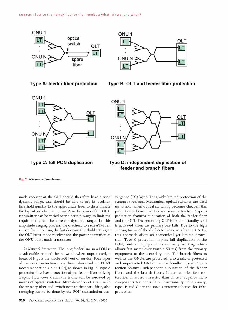
C. Wavelength Broadcast-and-Select Access NetworkFig. 16 presents a multiwavelength overlay of a
number of ATM PON networks on a HFC network,
following the wavelength channel selection approach [21].
Fig. 16(a) shows a fiber-coax network for distribution ofCATV services, operating at a wavelength �0 in the 1550–
1560 nm window where erbium-doped fiber amplifiers
(EDFA-s) offer their best output power performance.
Thus, using several EDFA-s in cascade, an extensive
optical network splitting factor can be realized and a large
number of customers can be served. For example, with
two optical amplifier stages and typical splitting factors of
N ¼ 4 and P ¼ 16, and a minifiber node serving 40 usersvia its coaxial network, a total of 2560 users is served from
a single headend fiber. For interactive services, the
upstream frequency band in a standard HFC network
(with a width of some 40–60 MHz) has to be shared
among these users, thus limiting the bitrate per user to
narrowband services such as voice telephony.
An upgrade of the system in order to provide
broadband interactive services can be realized by overlay-ing the HFC network with a number of wavelength-
multiplexed bidirectional data systems. In the ACTS
TOBASCO project [21], such an overlay was made with
four APON systems; see Fig. 16(b) Four APON OLT-s
at the headend site are providing each bidirectional
622-Mbit/s ATM signals on a specific downstream and
upstream wavelength. These eight wavelengths are
positioned in the 1535–1541-nm window, where the up-
and downstream wavelength channels are interleaved with
100-GHz spacing. The APON wavelengths are combinedby a high-density wavelength division multiplexer
(HDWDM), and subsequently multiplexed with the
CATV signal by means of a simple coarse wavelength
multiplexer (thanks to the wide spacing between the band
of APON wavelengths and the CATV wavelength band).
The system upgrade implies also replacement of the
unidirectional optical erbium-doped fiber amplifiers by
bidirectional ones which feature low noise high-poweroperation for the downstream CATV signal, and for the
bidirectional ATM signals a wavelength-flattened gain
curve plus a nonsaturated behavior (to suppress crosstalk
in burst-mode). At the ONU site, first the CATV signal is
separated from the APON signals by means of a coarse
wavelength multiplexer, and is subsequently converted to
an electrical CATV signal by a highly linear receiver and
distributed to the users via the coaxial network. TheAPON signals are fed to a wavelength-switched transceiv-
er, of which the receiver can be switched to any of the four
downstream wavelength channels, and the transmitter to
any of the four upstream ones. The wavelength-switched
transceiver may be implemented by an array of wave-
length-specific transmitters and receivers, which can be
individually switched on and off; this configuration allows
to set up a new wavelength channel before breaking downthe old one (Bmake-before-break[). Alternatively, it may
use wavelength-tunable transmitters and receivers, which
can in principle address any wavelength in a certain range;
this eases further upgrading of the system by introducing
more wavelength channels, but also implies a Bbreak-
before-make[ channel switching. The network manage-
ment and control system commands to which down-
stream and to which upstream wavelength channel eachONU transceiver is switched. By issuing these commands
from the headend station, the network operator actually
Fig. 15. Dynamically allocating wavelength channels to ONU-s. (a) Broadcast-and-select. (b) Flexible wavelength routing.
Koonen: Fiber to the Home/Fiber to the Premises: What, Where, and When?
Vol. 94, No. 5, May 2006 | Proceedings of the IEEE 925
controls the virtual topology of the network, and thus is
able to allocate the network’s capacity resources inresponse to the traffic demands at the various ONU
sites. The network management command signals are
transported via an out-of-band wavelength channel in the
1.3-�m wavelength window. The APON signals channel
selected by the ONU is converted into a bidirectional
electrical broadband data signal by the transceiver, which
is by a cable modem controller put in appropriate
frequency band for multiplexing with the electrical CATVsignal. The upstream data signal is usually put below the
lowest frequency CATV signal (so below 40–50 MHz),
and the downstream signal in empty frequency bands
between the CATV broadcast channels. The signals are
carried by the coaxial network (in which only the
electrical amplifiers need to be adapted to handle thebroadband data signals) to the customer homes, where
the CATV signal is separated from the bidirectional data
signals; the latter signals are processed by a cable modem,
which interacts with the cable modem controller at the
ONU site. This system has been successfully deployed in
a field trial [21].
By remotely changing the wavelength selection at the
ONU-s, the network operator can adjust the system’scapacity allocation in order to meet the local traffic
demands at the ONU sites. As illustrated in Fig. 17, the
ONU-s are allocated to the four upstream (and
downstream) wavelength channels, which each have a
Fig. 16. Flexible capacity assignment in a multiwavelength fiber-coax network by wavelength selection at the ONU-s. (a) Fiber-coax network for
distribution of CATV services. (b) Upgrading of the fiber-coax network with multiwavelength APON system for delivery of broadband
interactive services.
Koonen: Fiber to the Home/Fiber to the Premises: What, Where, and When?
926 Proceedings of the IEEE | Vol. 94, No. 5, May 2006
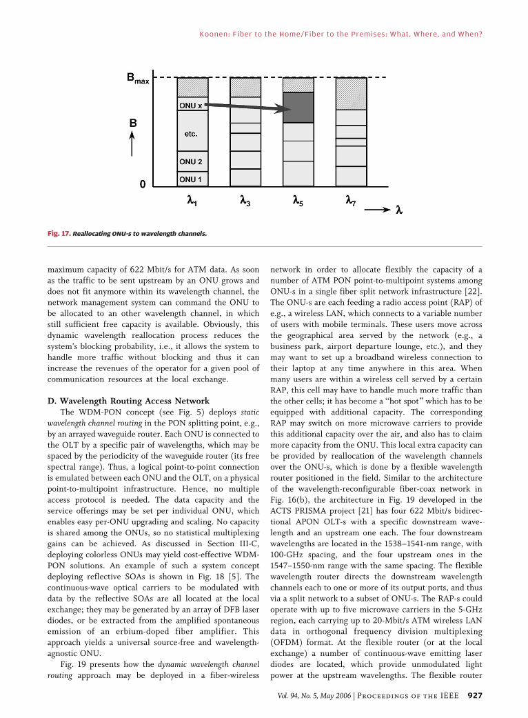
maximum capacity of 622 Mbit/s for ATM data. As soonas the traffic to be sent upstream by an ONU grows and
does not fit anymore within its wavelength channel, the
network management system can command the ONU to
be allocated to an other wavelength channel, in which
still sufficient free capacity is available. Obviously, this
dynamic wavelength reallocation process reduces the
system’s blocking probability, i.e., it allows the system to
handle more traffic without blocking and thus it canincrease the revenues of the operator for a given pool of
communication resources at the local exchange.
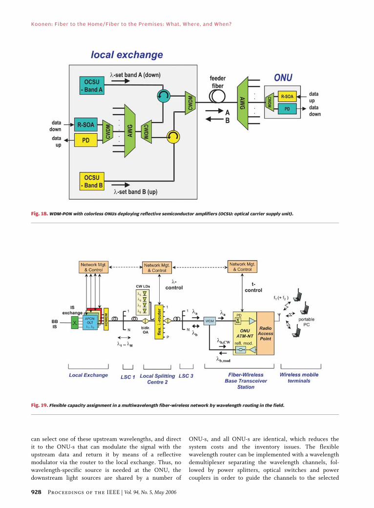
D. Wavelength Routing Access NetworkThe WDM-PON concept (see Fig. 5) deploys static
wavelength channel routing in the PON splitting point, e.g.,
by an arrayed waveguide router. Each ONU is connected to
the OLT by a specific pair of wavelengths, which may bespaced by the periodicity of the waveguide router (its free
spectral range). Thus, a logical point-to-point connection
is emulated between each ONU and the OLT, on a physical
point-to-multipoint infrastructure. Hence, no multiple
access protocol is needed. The data capacity and the
service offerings may be set per individual ONU, which
enables easy per-ONU upgrading and scaling. No capacity
is shared among the ONUs, so no statistical multiplexinggains can be achieved. As discussed in Section III-C,
deploying colorless ONUs may yield cost-effective WDM-
PON solutions. An example of such a system concept
deploying reflective SOAs is shown in Fig. 18 [5]. The
continuous-wave optical carriers to be modulated with
data by the reflective SOAs are all located at the local
exchange; they may be generated by an array of DFB laser
diodes, or be extracted from the amplified spontaneousemission of an erbium-doped fiber amplifier. This
approach yields a universal source-free and wavelength-
agnostic ONU.
Fig. 19 presents how the dynamic wavelength channelrouting approach may be deployed in a fiber-wireless
network in order to allocate flexibly the capacity of anumber of ATM PON point-to-multipoint systems among
ONU-s in a single fiber split network infrastructure [22].
The ONU-s are each feeding a radio access point (RAP) of
e.g., a wireless LAN, which connects to a variable number
of users with mobile terminals. These users move across
the geographical area served by the network (e.g., a
business park, airport departure lounge, etc.), and they
may want to set up a broadband wireless connection totheir laptop at any time anywhere in this area. When
many users are within a wireless cell served by a certain
RAP, this cell may have to handle much more traffic than
the other cells; it has become a Bhot spot[ which has to be
equipped with additional capacity. The corresponding
RAP may switch on more microwave carriers to provide
this additional capacity over the air, and also has to claim
more capacity from the ONU. This local extra capacity canbe provided by reallocation of the wavelength channels
over the ONU-s, which is done by a flexible wavelength
router positioned in the field. Similar to the architecture
of the wavelength-reconfigurable fiber-coax network in
Fig. 16(b), the architecture in Fig. 19 developed in the
ACTS PRISMA project [21] has four 622 Mbit/s bidirec-
tional APON OLT-s with a specific downstream wave-
length and an upstream one each. The four downstreamwavelengths are located in the 1538–1541-nm range, with
100-GHz spacing, and the four upstream ones in the
1547–1550-nm range with the same spacing. The flexible
wavelength router directs the downstream wavelength
channels each to one or more of its output ports, and thus
via a split network to a subset of ONU-s. The RAP-s could
operate with up to five microwave carriers in the 5-GHz
region, each carrying up to 20-Mbit/s ATM wireless LANdata in orthogonal frequency division multiplexing
(OFDM) format. At the flexible router (or at the local
exchange) a number of continuous-wave emitting laser
diodes are located, which provide unmodulated light
power at the upstream wavelengths. The flexible router
Fig. 17. Reallocating ONU-s to wavelength channels.
Koonen: Fiber to the Home/Fiber to the Premises: What, Where, and When?
Vol. 94, No. 5, May 2006 | Proceedings of the IEEE 927
can select one of these upstream wavelengths, and direct
it to the ONU-s that can modulate the signal with theupstream data and return it by means of a reflective
modulator via the router to the local exchange. Thus, no
wavelength-specific source is needed at the ONU, the
downstream light sources are shared by a number of
ONU-s, and all ONU-s are identical, which reduces the
system costs and the inventory issues. The flexiblewavelength router can be implemented with a wavelength
demultiplexer separating the wavelength channels, fol-
lowed by power splitters, optical switches and power
couplers in order to guide the channels to the selected
Fig. 19. Flexible capacity assignment in a multiwavelength fiber-wireless network by wavelength routing in the field.
Fig. 18. WDM-PON with colorless ONUs deploying reflective semiconductor amplifiers (OCSU: optical carrier supply unit).
Koonen: Fiber to the Home/Fiber to the Premises: What, Where, and When?
928 Proceedings of the IEEE | Vol. 94, No. 5, May 2006

output port(s). Depending on the granularity of thewavelength allocation process, the flexible router may be
positioned at various splitting levels in the network.
Using a similar strategy to assign wavelength channels
to the ONU-s as depicted in Fig. 17, a statistical
performance analysis has been performed of the blocking
probability of the system. It was assumed that the total
network served 343 cells, of which 49 were Bhot spots,[i.e., generated a traffic load two times as large as aregular cell. It was also assumed that the system deployed
seven wavelength channels, and that the calls arrived
following a Poisson process where the call duration and
length were uniformly distributed. Fig. 20 shows how
the system blocking probability depends on the offered
load (normalized on the total available capacity, which is
7 times 622 Mbit/s), using various system architecture
options. In the static WDM case (i.e., when wavelengthreallocation is not possible) where all the 49 hot spots
are served by ONU-s assigned to the same wavelength
channel, this obviously yields the worst-case blocking
probability. On the other hand, in the static WDM case
where the 49 hot spots were evenly spread over the
seven wavelength channels, the blocking probability is
much lower (i.e., best case). Unfortunately, a network
operator cannot know beforehand where the hot spotswill be positioned, so in an arbitary static WDM case the
system blocking probability will be anywhere between
the best case and the worst case, and no guarantee for a
certain blocking performance can be given. When,
however, dynamic reallocation of the wavelength chan-
nels is possible, the system can adapt to the actual hot
spot distribution. Fig. 20 shows that when the flexible
wavelength router is positioned at the second splittingpoint in the network, the blocking performance is better
than the best-case static WDM performance; but more
importantly, it is also stable against variations in the hot
spot distribution, and thus would allow an operator to
guarantee a certain system blocking performance while
still optimizing the efficiency of his system’s capacity
resources. The blocking performance may be even better
and more stable when positioning the flexible router atthe third splitting point; however, this implies that the
costs of the router are shared by less ONU-s. Locating
the router at the second splitting point is considered to
yield a good compromise between adequate improve-
ment of the system blocking performance and system
costs per ONU.
VII. RADIO OVER FIBER
Wireless communication services are steadily increasing
their share of the telecommunication market. Next to their
prime feature, mobility, they are offering growing
bandwidths to the end users. This asks for smaller radio
cells, and thus for higher radio carrier frequencies, which
incur increased propagation losses and line-of-sight needs.
Wireless LANs in the 2.4-GHz range according to the IEEE802.11b standard carry up to 11 Mbit/s, and up to 54 Mbit/s
in the IEEE 802.11g standard. The IEEE 802.11a and the
HIPERLAN/2 standard provide up to 54 Mbit/s in the
5.4-GHz range. Research is ongoing in systems that may
deliver more than 100 Mbit/s in the radio frequency
range well above 10 GHz (e.g., LMDS at 28 GHz,
HyperAccess at 17 GHz and 42 GHz, MVDS at 40 GHz,
MBS at 60 GHz, etc.). Due to the shrinkage of radiocells at higher radio frequencies, ever more antenna sites
are needed to cover a certain area such as the rooms in an
office building, in a hospital, the departure lounges of an
airport, etc. Thus, more RAPs are needed to serve e.g., all
the rooms in an office building, and hence also a more
extensive wired network is needed to feed these RAPs.
Instead of generating the microwave signals at each
RAP individually, feeding the microwave signals from acentral headend site to the RAPs enables to simplify the
RAPs and thus to reduce their costs considerably. In this
radio-over-fiber approach, the signal processing functions
can be consolidated at the headend site, which allows more
sophisticated signal processing, eases upgrading to new
wireless standards. Thanks to its broadband character-
istics, optical fiber is an excellent medium to bring the
microwave signals to the RAPs.
A. Intensity Modulation/Direct Detection SystemsRadio over fiber systems using direct microwave
intensity modulation of a laser diode are commercially
available up to limited radio frequencies (up to about
2 GHz, for wireless services such as GSM and UMTS). The
operation at higher microwave frequencies is prohibited by
the restricted modulation bandwidth of the laser diode andby the fiber dispersion, which causes fading of the two
modulation sidebands. Such microwave frequencies may
only be handled by sophisticated very high frequency
Fig. 20. Improving the system performance by dynamic wavelength
allocation.
Koonen: Fiber to the Home/Fiber to the Premises: What, Where, and When?
Vol. 94, No. 5, May 2006 | Proceedings of the IEEE 929

optical analog transmitters and receivers, and careful fiber
dispersion compensation techniques [23]. Operation at
higher microwave frequencies may be more easily achieved
by the advanced radio over fiber techniques being inves-tigated in research laboratories, of which two examples are
given in the next sections.
B. Heterodyning SystemsAn attractive alternative avoiding the transport of
multi-GHz intensity-modulated signals through the fiber is
to apply heterodyning of two optical signals of which the
difference in optical frequency (wavelength) correspondsto the microwave frequency. When one of these signals is
intensity-modulated with the baseband data to be
transported, and the other one is unmodulated, by optical
heterodyning at the photodiode in the receiver the
electrical microwave difference frequency signal is gener-
ated, amplitude-modulated with the data signal. This
modulated microwave signal can via a simple amplifier be
radiated by an antenna. Thus, a very simple low-cost radioaccess point can be realized, while the complicated signal
processing is consolidated at the headend station.
This approach, however, requires two light sources
with narrow spectral linewidth and carefully stabilized
difference in optical emission frequency. An alternative
approach requiring only a single optical source is shown in
Fig. 21 [24]. The optical intensity-modulated signal from a
laser diode is subsequently intensity-modulated by anexternal Mach–Zehnder modulator (MZM) which is
biased at its inflexion point of the modulation character-
istic and driven by a sinusoidal signal at half the microwave
frequency. Thus, at the MZM’s output port, a two-tone
optical signal emerges, with a tone spacing equal to the
microwave frequency. After heterodyning in a photodiode,
the desired amplitude-modulated microwave signal is
generated. The transmitter may also use multiple laserdiodes, and thus a multiwavelength radio-over-fiber system
can be realized with a (tunable) WDM filter to select the
desired wavelength radio channel at the antenna site. The
system is tolerant to fiber dispersion, and also the laser
linewidth is not critical as laser phase noise is largelyeliminated in the two-tone detection process.
C. Optical Frequency Multiplying SystemsAn alternative approach to generate microwave
signals by means of a different kind of remote optical
processing, named optical frequency multiplying (OFM), is
shown in Fig. 22 [25], [26]. At the headend station the
wavelength �0 of a tunable laser diode is sweptperiodically over a certain range ��sw, with a sweep
frequency fsw. Alternatively, the wavelength-swept signal
can be generated with a continuous-wave operating laser
diode followed by an external phase modulator that is
driven with the integral of the electrical sweep waveform.
In a symmetrically driven Mach–Zehnder modulator, the
intensity of the wavelength-swept signal is on/off
modulated (with low frequency chirp) by the downstreamdata. After travelling through the fiber network, the
signal transverses at the receiver an optical filter with a
periodic bandpass characteristic. When the wavelength of
the signal is swept back and forth over N filter
transmission peaks, the light intensity impinging on the
photodiode fluctuates at a frequency 2N � fsw. Thus, the
sweep frequency is multiplied, and a microwave signal
with carrier frequency fmm ¼ 2N � fsw plus higher harmo-nics is obtained. The intensity-modulated data is not
affected by this multiplication process, and is maintained
as the envelope of the microwave signal. The microwave
signal is subsequently traversing an electrical bandpass
filter (BPF) that rejects the unwanted microwave
harmonics. Analysis and simulations have shown that
the microwave signal is very pure; the inherent
cancellation of the laser’s optical phase noise makesthat the spectral linewidth of the microwave signal is
Fig. 21. Generating microwave signals by heterodyning.
Koonen: Fiber to the Home/Fiber to the Premises: What, Where, and When?
930 Proceedings of the IEEE | Vol. 94, No. 5, May 2006
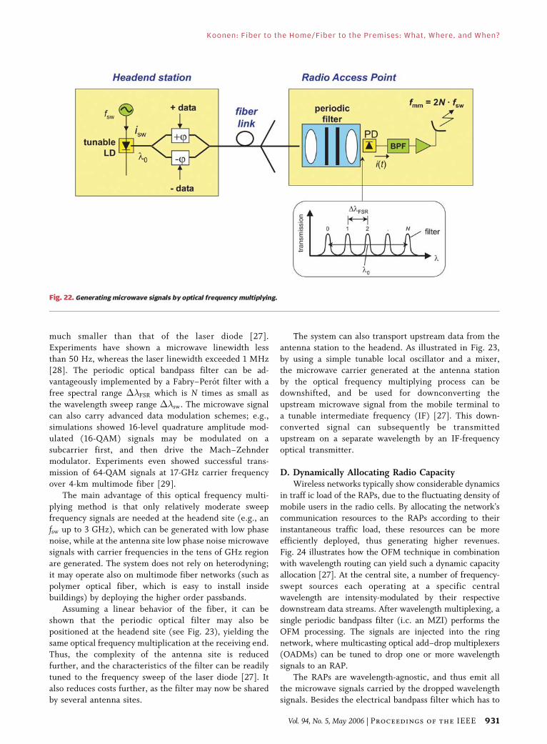
much smaller than that of the laser diode [27].
Experiments have shown a microwave linewidth less
than 50 Hz, whereas the laser linewidth exceeded 1 MHz[28]. The periodic optical bandpass filter can be ad-
vantageously implemented by a Fabry–Perot filter with a
free spectral range ��FSR which is N times as small as
the wavelength sweep range ��sw. The microwave signal
can also carry advanced data modulation schemes; e.g.,
simulations showed 16-level quadrature amplitude mod-
ulated (16-QAM) signals may be modulated on a
subcarrier first, and then drive the Mach–Zehndermodulator. Experiments even showed successful trans-
mission of 64-QAM signals at 17-GHz carrier frequency
over 4-km multimode fiber [29].
The main advantage of this optical frequency multi-
plying method is that only relatively moderate sweep
frequency signals are needed at the headend site (e.g., an
fsw up to 3 GHz), which can be generated with low phase
noise, while at the antenna site low phase noise microwavesignals with carrier frequencies in the tens of GHz region
are generated. The system does not rely on heterodyning;
it may operate also on multimode fiber networks (such as
polymer optical fiber, which is easy to install inside
buildings) by deploying the higher order passbands.
Assuming a linear behavior of the fiber, it can be
shown that the periodic optical filter may also be
positioned at the headend site (see Fig. 23), yielding thesame optical frequency multiplication at the receiving end.
Thus, the complexity of the antenna site is reduced
further, and the characteristics of the filter can be readily
tuned to the frequency sweep of the laser diode [27]. It
also reduces costs further, as the filter may now be shared
by several antenna sites.
The system can also transport upstream data from the
antenna station to the headend. As illustrated in Fig. 23,
by using a simple tunable local oscillator and a mixer,the microwave carrier generated at the antenna station
by the optical frequency multiplying process can be
downshifted, and be used for downconverting the
upstream microwave signal from the mobile terminal to
a tunable intermediate frequency (IF) [27]. This down-
converted signal can subsequently be transmitted
upstream on a separate wavelength by an IF-frequency
optical transmitter.
D. Dynamically Allocating Radio CapacityWireless networks typically show considerable dynamics
in traff ic load of the RAPs, due to the fluctuating density of
mobile users in the radio cells. By allocating the network’s
communication resources to the RAPs according to their
instantaneous traffic load, these resources can be more
efficiently deployed, thus generating higher revenues.Fig. 24 illustrates how the OFM technique in combination
with wavelength routing can yield such a dynamic capacity
allocation [27]. At the central site, a number of frequency-
swept sources each operating at a specific central
wavelength are intensity-modulated by their respective
downstream data streams. After wavelength multiplexing, a
single periodic bandpass filter (i.c. an MZI) performs the
OFM processing. The signals are injected into the ringnetwork, where multicasting optical add–drop multiplexers
(OADMs) can be tuned to drop one or more wavelength
signals to an RAP.
The RAPs are wavelength-agnostic, and thus emit all
the microwave signals carried by the dropped wavelength
signals. Besides the electrical bandpass filter which has to
Fig. 22. Generating microwave signals by optical frequency multiplying.
Koonen: Fiber to the Home/Fiber to the Premises: What, Where, and When?
Vol. 94, No. 5, May 2006 | Proceedings of the IEEE 931
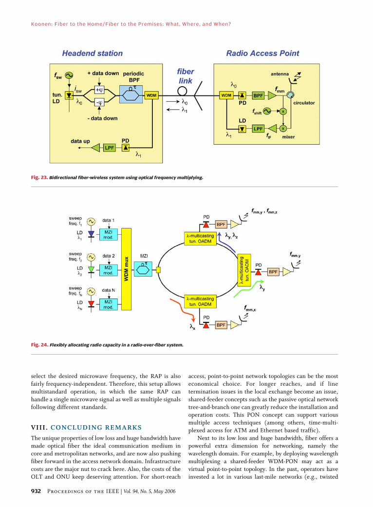
select the desired microwave frequency, the RAP is also
fairly frequency-independent. Therefore, this setup allows
multistandard operation, in which the same RAP can
handle a single microwave signal as well as multiple signals
following different standards.
VIII. CONCLUDING REMARKS
The unique properties of low loss and huge bandwidth have
made optical fiber the ideal communication medium in
core and metropolitan networks, and are now also pushing
fiber forward in the access network domain. Infrastructure
costs are the major nut to crack here. Also, the costs of theOLT and ONU keep deserving attention. For short-reach
access, point-to-point network topologies can be the most
economical choice. For longer reaches, and if line
termination issues in the local exchange become an issue,
shared-feeder concepts such as the passive optical network
tree-and-branch one can greatly reduce the installation andoperation costs. This PON concept can support various
multiple access techniques (among others, time-multi-
plexed access for ATM and Ethernet based traffic).
Next to its low loss and huge bandwidth, fiber offers a
powerful extra dimension for networking, namely the
wavelength domain. For example, by deploying wavelength
multiplexing a shared-feeder WDM-PON may act as a
virtual point-to-point topology. In the past, operators haveinvested a lot in various last-mile networks (e.g., twisted
Fig. 24. Flexibly allocating radio capacity in a radio-over-fiber system.
Fig. 23. Bidirectional fiber-wireless system using optical frequency multiplying.
Koonen: Fiber to the Home/Fiber to the Premises: What, Where, and When?
932 Proceedings of the IEEE | Vol. 94, No. 5, May 2006

pair, coaxial cable) to reach their residential customers. Inupgrading these networks to higher capacity and larger
service variety, fiber may penetrate further toward the
customer. It can support a wide range of last-mile
technologies by hybrid combinations such as fiber-twisted
pair, fiber-coax, and fiber-wireless. By means of adjustable
wavelength routing techniques, the fiber feeder part of such
hybrid networks can flexibly accommodate different
operators and service categories. With dynamically adjust-able wavelength routing, capacity-on-demand can be
realized for efficient management of fluctuating traffic
patterns, while respecting quality-of-service requirements.
Combining the huge bandwidth of fiber with the
mobility offered by wireless communication makes fiber-
wireless networks an attractive access scenario. By
transporting the radio signals over fiber, the antenna sites
of broadband wireless systems can be significantlysimplified and thus system costs be reduced, whereas
also more sophisticated signal processing (for e.g., antenna
diversity systems) is facilitated. In combination with
wavelength routing, powerful options for hot-spot han-
dling can be devised.
IX. FUTURE PROSPECTS
The end user is still to benefit fully from all these
ultrabroadband communication possibilities. Therefore,
the optical fiber not only needs to reach up to his house,but needs to penetrate into it as well. It may reach close to
his personal area network, which thanks to the ongoing
miniaturization may consist of a myriad of small wireless
power-lean terminals, sensors and actuators. These wire-
less devices may be incorporated not only in his residential
living environment, but also in his clothes, his car, etc.
Next to the traditional wired terminals such as the TV and
desktop PC, these wireless devices may be connected tothe fixed in-home and access network by a myriad of small
intelligent antennas. Radio-over-fiber techniques, aug-
mented with optical routing to accommodate dynamically
the hot spots, may provide the best match of the ultimate
capacity of fiber with the user freedom of wireless. Even in
the wireless domain, optics may penetrate by means of
intelligently steered free-space light beams providing the
ultimate in wireless transport capacity.Which in the far foreseeable future may make the
communication world an end-to-end globally transparent
one, with nearly unlimited communication capacity for
anybody, anytime, anywhere, for any kind of service . . .the ultimate global crystal ball! h
Acknowledgment
The author would like to thank the partners in the var-
ious projects mentioned for their valuable contributions.
RE FERENCES
[1] N. J. Frigo, P. P. Iannone, and K. C.Reichmann, BA view of fiber to the homeeconomics,[ IEEE Commun. Mag., vol. 42,no. 8, pp. S16–S23, Aug. 2004.
[2] T. Koonen, H. van den Boom, and G.-D. Khoe,BBroadband access and in-housenetworksVextending the capabilities ofmultimode fiber networks,[ presented at theECOC 2003, Rimini, Italy, Paper Mo3.1.5.
[3] N. J. Frigo, P. P. Iannone, and K. C.Reichmann, BSpectral slicing in WDM passiveoptical networks for local access,[ in Proc.ECOC 1998, pp. 119–120.
[4] N. J. Frigo, P. P. Iannone, K. C. Reichmann,J. A. Walker, K. W. Goossen, S. C. Arney,E. J. Murphy, Y. Ota, and R. G. Swartz,BDemonstration of performance-tieredmodulators in a WDM PON with asingle shared source,[ in Proc. ECOC 1995,pp. 441–444.
[5] S.-J. Park, G.-Y. Kim, and T.-S. Park, BWDM-PON system based on the laser light injectedreflective semiconductor optical amplifier,[in Proc. OECC 2005, pp. 160–161,Paper 6A4-3.
[6] D. K. Jung, D. J. Shin, H. S. Shin, H. S. Kim,S. B. Park, S. Hwang, Y. J. Oh, and C. S. Shim,BWavelength-division-multiplexed passiveoptical network for FTTx,[ in Proc. OECC2005, pp. 380–381, Paper 7A3-6.
[7] R. Adams, J. Faucher, L. R. Chen, J. Bajcsy,and D. V. Plant, BDemonstration ofencoding/decoding 2-D wavelength-timebipolar codes for optical CDMA,[ in Proc.OECC 2005, pp. 760–761, Paper 8A3-1.
[8] H. Ueda, K. Okada, B. Ford, G. Mahony,S. Hornung, D. Faulkner, J. Abiven, S. Durel,R. Ballart, and J. Erickson, BDeployment
status and common technical specificationsfor a B-PON system,[ IEEE Commun.Mag., vol. 39, no. 12, pp. 134–141, Dec. 2001.
[9] F. J. Effenberger, H. Ichibangase, andH. Yamashita, BAdvances in broadbandpassive optical networking technologies,[IEEE Commun. Mag., vol. 39, no. 12,pp. 118–124, Dec. 2001.
[10] K. I. Suzuki, N. Hirachi, T. Shibuya, andK. Saito, BOptical burst receiver for multi-bitrate G-PON system,[ presented at the ECOC2004, Stockholm, Sweden, Paper We2.6.5.
[11] R. Schoop, F. Fredericx, T. Koonen, andC. Hardalov, BWDM isolation requirementsfor CATV in BPON,[ presented at the ECOC2002, Copenhagen, Denmark.
[12] P. Vetter, F. Fredericx, E. Ringoot,N. Janssens, B. de Vos, C. Bouchat,F. Duthilleul, C. Dessauvages, B. Stubbe,E. Gilon, M. Tassent, X. Z. Qiu, J. Vandewege,P. Ossieur, J. Bauwelinck, J. Watte, andC. Blondia, BStudy and demonstration ofextensions to the standard FSAN BPON,[ inProc. 14th Int. Symp. Services and Local Access(ISSLS 2002), pp. 119–128, Paper 4-2.
[13] I. van de Voorde, C. Martin, E. Ringoot,H. Slabbinck, M. Tassent, C. Bouchat,D. Goderis, and P. Vetter, BThe super PONdemonstrator: A versatile platform to evaluatepossible upgrades of the G.983 APON,[presented at the 13th Int. Symp. Servicesand Local Access (ISSLS 2000), Stockholm,Sweden, Paper 14-3.
[14] D. Nesset, M. Scopes, R. Davey, D. Shea,P. Healey, A. Borghesani, D. Moodie,A. Poustie, and R. Wyatt, BDemonstration of100 km reach amplified PON’s with upstreambitrates of 2.5 and 10 Gb/s,[ presented at theECOC 2004, Stockholm, Sweden,Paper We2.6.3.
[15] IEEE 802.3ah Ethernet in the first mile taskforce. [Online]. Available: http://www.ieee802.org/3/efm/index.html.
[16] J. Zheng and H. T. Mouftah, BMedia accesscontrol for ethernet passive opticalnetworks: an overview,[ IEEE Commun.Mag., vol. 43, no. 2, pp. 145–150,Feb. 2005.
[17] T. Van Caenegem, E. Gilon, X. Z. Qiu,K. Cobb, and P. Solina, BPrototyping ITU-TGPON, the new efficient and flexible FTTPsolution,[ presented at the ISSLS 2004,Edinburgh, U.K.
[18] J. D. Angelopoulos, H.-C. Leligou,T. Argyriou, S. Zontos, E. Ringoot, andT. Van Caenegem, BEfficient transport ofpackets with QoS in an FSAN-alignedGPON,[ IEEE Commun. Mag., vol. 42, no. 2,pp. 92–98, Feb. 2004.
[19] G. Donaldson and D. Jones, BCable televisionbroadband network architectures,[ IEEECommun. Mag., vol. 39, no. 6, pp. 122–126,Jun. 2001.
[20] A. M. J. Koonen and G. D. Khoe, BFlexibleservice delivery in access and local networks,’’presented at the OECC 2005, Seoul, Korea,Paper 7A3-1.
[21] T. Koonen, T. Muys, C. van der Plaats, S. M.Heemstra de Groot, H. J. H. N. Kenter, I. G.M. M. Niemegeers, and F. N. C. Slothouber,BTOBASCO: an innovative approach forupgrading CATV fiber-coax networks forbroadband interactive services,[ IEEECommun. Mag., vol. 35, no. 4, pp. 76–81,Apr. 1997.
[22] T. Koonen, K. Steenbergen, F. Janssen, andJ. Wellen, BFlexible reconfigurablefiber-wireless network using wavelengthrouting techniques: the ACTS project
Koonen: Fiber to the Home/Fiber to the Premises: What, Where, and When?
Vol. 94, No. 5, May 2006 | Proceedings of the IEEE 933

AC349 PRISMA,[ Photon. Netw. Commun.,vol. 3, no. 3, pp. 297–306, Jul. 2001,1387-974x.
[23] K. Kitayama and H. Sotabayashi,BCancellation of the signal fading for60 GHz sub-carrier multiplexed optical DSBsignal transmission in nondispersion shitedfiber using midway optical phaseconjugation,[ J. Lightw. Technol., vol. 17,no. 12, pp. 2488–2497, Dec. 1999.
[24] R. A. Griffin, P. M. Lane, and J. J. O’Reilly,BRadio-over-fiber distribution using an opticalmillimeter-wave/DWDM overlay,[ presentedat the OFC ’99, San Diego, CA, Paper WD6.
[25] T. Koonen, A. Ng’oma, P. Smulders,H. van den Boom, I. Tafur Monroy,
P. van Bennekom, and G.-D. Khoe, BIn-housenetworks using polymer optical fiber forbroadband wireless applications,[ in Proc.14th Int. Symp. Services and Local Access (ISSLS2002), pp. 285–294.
[26] T. Koonen, A. Ng’oma, P. Smulders,H. van den Boom, I. Tafur Monroy, andG.-D. Khoe, BIn-house networks usingmultimode polymer optical fiber forbroadband wireless services,[ Photon. Netw.Commun., vol. 5, no. 2, pp. 177–187,Mar. 2003.
[27] T. Koonen, A. Ng’oma, M. G. Larrode,F. Huijskens, I. Tafur Monroy, andG.-D. Khoe, BNovel cost-efficient techniquesfor microwave signal delivery in fiber-wireless
networks,[ presented at the ECOC 2004,Stockholm, Sweden, Paper Th1.1.1.
[28] A. Ng’oma, I. Tafur Monroy, T. Koonen,H. van den Boom, P. Smulders, andG.-D. Khoe, BHigh-frequency carrier deliveryto graded index polymer optical fiber fednext generation wireless LAN radio accesspoints,[ in Proc. ECOC 2003, Rimini,Sep. 21–25, 2003.
[29] A. Ng’oma, A. M. J. Koonen, I. Tafur Monroy,H. P. A. van den Boom, and G.-D. Khoe,BUsing optical frequency multiplication todeliver a 17 GHz 64-QAM modulated signal toa simplified radio access unit fed bymultimode fiber,[ presented at the Proc. OFC2005, Anaheim, CA, Paper OWB2.
ABOUT THE AUT HOR
Ton Koonen (Senior Member, IEEE) is a full prof-
essor in the Department of Electrical Engineering,
Eindhoven University of Technology, Eindhoven,
The Netherlands, since 2001. He also is affiliated
to the COBRA Institute at the same university.
Prior to this position, he spent more than 20 years
at Bell Labs in Lucent Technologies as a Technical
Manager of Applied Research. He is a Bell Labs
Fellow. Next to his industrial position, he was a
Part-Time Professor at Twente University from
1991 to 2000. His main interests are currently in broadband fiber access
networks. He has initiated and led several European and national R&D
projects in this area, among others in dynamically reconfigurable hybrid
fiber access networks for fiber-to-the-curb and fiber-to-the-building.
Currently, he is leading the European FP5 IST project STOLAS on optical
packet labeling as well as national projects in access and in-building
networks, and he is involved in several projects in this area in the
European FP6 IST program (among others MUSE and e-Photon/ONe).1
Koonen: Fiber to the Home/Fiber to the Premises: What, Where, and When?
934 Proceedings of the IEEE | Vol. 94, No. 5, May 2006


![Digital signal processing for fiber nonlinearities [Invited]Digital signal processing for fiber nonlinearities [Invited] JOHN C. CARTLEDGE,1,* FERNANDO P. GUIOMAR,2,6 FRANK R. KSCHISCHANG,3,7](https://img.pdfslide.us/doc/110x75/5e3d57cfe9dd732fff42ee6d/digital-signal-processing-for-fiber-nonlinearities-invited-digital-signal-processing.jpg)


![Digital signal processing for fiber nonlinearities [Invited]orbit.dtu.dk/files/132396109/oe_25_3_1916.pdf · Digital signal processing for fiber nonlinearities [Invited] JOHN C. CARTLEDGE,1,*](https://img.pdfslide.us/doc/110x75/5c6c589a09d3f262278c44da/digital-signal-processing-for-fiber-nonlinearities-invitedorbitdtudkfiles132396109oe2531916pdf.jpg)


![High power fiber lasers current status and future perspectives [invited]](https://img.pdfslide.us/doc/110x75/53ff3ea88d7f7250208b45c8/high-power-fiber-lasers-current-status-and-future-perspectives-invited.jpg)