Embed Size (px)
Citation preview
1688IEICE TRANS. COMMUN., VOL.E100–B, NO.9 SEPTEMBER 2017
INVITED PAPER Special Issue on the Past, Present, and Future of Communications Technologies in the IEICE
Development and Future of Optical Fiber Related Technologies
Shigeru TOMITA†a), Member
SUMMARY The history of optical fiber and optical transmission tech-nologies has been described in many publications. However, the history ofother technologies designed to support the physical layer of optical trans-mission has not been described in much detail. I would like to highlightthose technologies in addition to optical fibers. Therefore, this paper de-scribes the history of the development of optical fiber related technologiessuch as fusion splicers, optical fiber connectors, ribbon fiber, and passivecomponents based on changes in optical fibers and optical fiber cables.Moreover, I describe technologies designed to support multi-core fiberssuch as fan-in/fan-out devices.key words: optical fiber, fusion splicer, optical fiber connector, multi-corefiber, fan-in and fan-out device
1. Introduction
Optical fiber was invented in early 1970. In the early stages,multi-mode fibers were used, however, since the mid 1980ssingle-mode fibers have largely been employed. Opticalfiber and optical transmission techniques have subsequentlybeen modified to increase both transmission capacity anddistance. Their history has been described in many publica-tions. However, the history of other technologies designedto support the physical layer of optical transmission has re-ceived much less attention. In this work, I highlight thesetechnologies along with optical fiber. Optical fiber relatedtechnologies have been modified based on the changes madeto optical fiber and cable structures. For example, ribbonfibers were introduced in 1985 to make it possible to in-stall high-count optical fiber cables, and multi-fiber jointingtechnologies were introduced at the same time.
In 2010, the development of multi-core fiber started,because it was expected that there would be a limit to theincrease in transmission capacity that could be achieved bymodifying transmission technologies. A lot of new tech-nologies will be required if we are to realize high capacitytransmission using multicore fibers. Fan-in/fan-out devicesare described, which are an important technology with whichto activate multi-core fibers. This paper, describes the his-tory of optical fiber related technologies based on the changesin optical fiber geometrical structures.
Manuscript received September 23, 2016.Manuscript revised January 27, 2017.Manuscript publicized March 22, 2017.†The author is with NTT-AT, Tsukuba-shi, 305-0805 Japan.
a) E-mail: [email protected]: 10.1587/transcom.2016PFI0003
2. Coated Single-Mode Optical Fiber and Related Tech-nologies
2.1 Optical Fiber and Cable Structure
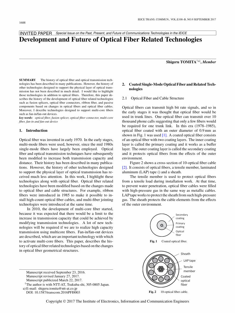
Optical fibers can transmit high bit rate signals, and so inthe early stages it was thought that optical fiber would beused in trunk lines. One optical fiber can transmit over 10thousand phone calls suggesting that only a few fibers wouldbe required for one trunk link. In this era (1978–1985),optical fiber coated with an outer diameter of 0.9 mm asshown in Fig. 1 was used [1]. A coated optical fiber consistsof an optical fiber with two coating layers. The inner coatinglayer is called the primary coating and it works as a bufferlayer. The outer coating layer is called the secondary coatingand it protects optical fibers from the effects of the outerenvironment.
Figure 2 shows a cross-section of 10-optical fiber cable[2]. It consists of optical fibers, a tensile member, laminatedaluminum (LAP) tape () and a sheath.
The tensile member is used to protect optical fibersfrom a tensile load during installation work. At that time,to prevent water penetration, optical fiber cables were filledwith high-pressure gas in the same way as metallic cables.LAP tape works to protect the sheath from such high-pressuregas. The sheath protects the cable elements from the effectsof the outer environment.
Fig. 1 Coated optical fiber.
Fig. 2 10-optical fiber cable.
Copyright © 2017 The Institute of Electronics, Information and Communication Engineers
TOMITA: DEVELOPMENT AND FUTURE OF OPTICAL FIBER RELATED TECHNOLOGIES1689
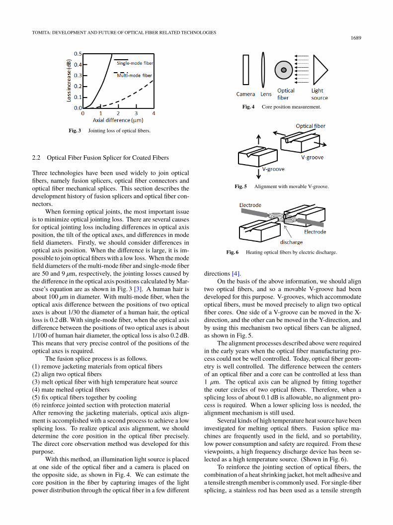
Fig. 3 Jointing loss of optical fibers.
2.2 Optical Fiber Fusion Splicer for Coated Fibers
Three technologies have been used widely to join opticalfibers, namely fusion splicers, optical fiber connectors andoptical fiber mechanical splices. This section describes thedevelopment history of fusion splicers and optical fiber con-nectors.
When forming optical joints, the most important issueis to minimize optical jointing loss. There are several causesfor optical jointing loss including differences in optical axisposition, the tilt of the optical axes, and differences in modefield diameters. Firstly, we should consider differences inoptical axis position. When the difference is large, it is im-possible to join optical fibers with a low loss. When the modefield diameters of the multi-mode fiber and single-mode fiberare 50 and 9 µm, respectively, the jointing losses caused bythe difference in the optical axis positions calculated by Mar-cuse’s equation are as shown in Fig. 3 [3]. A human hair isabout 100 µm in diameter. With multi-mode fiber, when theoptical axis difference between the positions of two opticalaxes is about 1/30 the diameter of a human hair, the opticalloss is 0.2 dB. With single-mode fiber, when the optical axisdifference between the positions of two optical axes is about1/100 of human hair diameter, the optical loss is also 0.2 dB.This means that very precise control of the positions of theoptical axes is required.
The fusion splice process is as follows.(1) remove jacketing materials from optical fibers(2) align two optical fibers(3) melt optical fiber with high temperature heat source(4) mate melted optical fibers(5) fix optical fibers together by cooling(6) reinforce jointed section with protection materialAfter removing the jacketing materials, optical axis align-ment is accomplished with a second process to achieve a lowsplicing loss. To realize optical axis alignment, we shoulddetermine the core position in the optical fiber precisely.The direct core observation method was developed for thispurpose.
With this method, an illumination light source is placedat one side of the optical fiber and a camera is placed onthe opposite side, as shown in Fig. 4. We can estimate thecore position in the fiber by capturing images of the lightpower distribution through the optical fiber in a few different
Fig. 4 Core position measurement.
Fig. 5 Alignment with movable V-groove.
Fig. 6 Heating optical fibers by electric discharge.
directions [4].On the basis of the above information, we should align
two optical fibers, and so a movable V-groove had beendeveloped for this purpose. V-grooves, which accommodateoptical fibers, must be moved precisely to align two opticalfiber cores. One side of a V-groove can be moved in the X-direction, and the other can be moved in the Y-direction, andby using this mechanism two optical fibers can be aligned,as shown in Fig. 5.
The alignment processes described above were requiredin the early years when the optical fiber manufacturing pro-cess could not be well controlled. Today, optical fiber geom-etry is well controlled. The difference between the centersof an optical fiber and a core can be controlled at less than1 µm. The optical axis can be aligned by fitting togetherthe outer circles of two optical fibers. Therefore, when asplicing loss of about 0.1 dB is allowable, no alignment pro-cess is required. When a lower splicing loss is needed, thealignment mechanism is still used.
Several kinds of high temperature heat source have beeninvestigated for melting optical fibers. Fusion splice ma-chines are frequently used in the field, and so portability,low power consumption and safety are required. From theseviewpoints, a high frequency discharge device has been se-lected as a high temperature source. (Shown in Fig. 6).
To reinforce the jointing section of optical fibers, thecombination of a heat shrinking jacket, hot melt adhesive anda tensile strength member is commonly used. For single-fibersplicing, a stainless rod has been used as a tensile strength
1690IEICE TRANS. COMMUN., VOL.E100–B, NO.9 SEPTEMBER 2017
member to realize long-term reliability and a low coefficientof thermal expansion. This type of optical fiber fusion splicerwas introduced in 1985.
2.3 Optical Fiber Connector for Mono-Coated Fiber
Until of the mid-1980s, the FC-connector was frequentlyused as an optical connector for single-mode fibers. How-ever, the FC-connector posed the following problems.
(1) Space is needed for connection and disconnection.
An FC connector requires a space of some 30 mm betweentwo connector plugs to allow a coupling nut to be rotatedwith the fingers.
(2) High ferrule cost
A ferrule consists of a ceramic capillary with a small holeprecisely positioned at the ferrule center and a stainless cylin-der. A ceramic capillary was installed into a stainless cylin-der, and both parts were processed using a high precision.
(3) High weight
Almost all the connector components were metal cproducts.In 1985, NTT considered that optical fibers would be
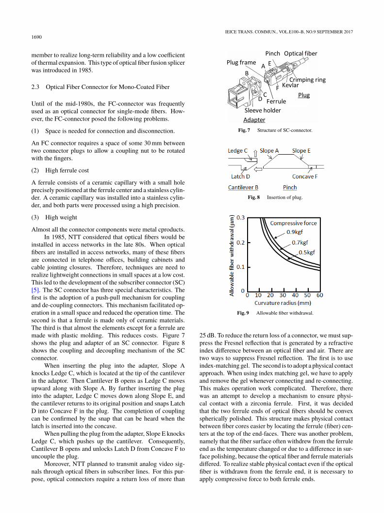
installed in access networks in the late 80s. When opticalfibers are installed in access networks, many of these fibersare connected in telephone offices, building cabinets andcable jointing closures. Therefore, techniques are need torealize lightweight connections in small spaces at a low cost.This led to the development of the subscriber connector (SC)[5]. The SC connector has three special characteristics. Thefirst is the adoption of a push-pull mechanism for couplingand de-coupling connectors. This mechanism facilitated op-eration in a small space and reduced the operation time. Thesecond is that a ferrule is made only of ceramic materials.The third is that almost the elements except for a ferrule aremade with plastic molding. This reduces costs. Figure 7shows the plug and adapter of an SC connector. Figure 8shows the coupling and decoupling mechanism of the SCconnector.
When inserting the plug into the adapter, Slope Aknocks Ledge C, which is located at the tip of the cantileverin the adaptor. Then Cantilever B opens as Ledge C movesupward along with Slope A. By further inserting the pluginto the adapter, Ledge C moves down along Slope E, andthe cantilever returns to its original position and snaps LatchD into Concave F in the plug. The completion of couplingcan be confirmed by the snap that can be heard when thelatch is inserted into the concave.
When pulling the plug from the adapter, Slope E knocksLedge C, which pushes up the cantilever. Consequently,Cantilever B opens and unlocks Latch D from Concave F touncouple the plug.
Moreover, NTT planned to transmit analog video sig-nals through optical fibers in subscriber lines. For this pur-pose, optical connectors require a return loss of more than
Fig. 7 Structure of SC-connector.
Fig. 8 Insertion of plug.
Fig. 9 Allowable fiber withdrawal.
25 dB. To reduce the return loss of a connector, we must sup-press the Fresnel reflection that is generated by a refractiveindex difference between an optical fiber and air. There aretwo ways to suppress Fresnel reflection. The first is to useindex-matching gel. The second is to adopt a physical contactapproach. When using index matching gel, we have to applyand remove the gel whenever connecting and re-connecting.This makes operation work complicated. Therefore, therewas an attempt to develop a mechanism to ensure physi-cal contact with a zirconia ferrule. First, it was decidedthat the two ferrule ends of optical fibers should be convexspherically polished. This structure makes physical contactbetween fiber cores easier by locating the ferrule (fiber) cen-ters at the top of the end-faces. There was another problem,namely that the fiber surface often withdrew from the ferruleend as the temperature changed or due to a difference in sur-face polishing, because the optical fiber and ferrule materialsdiffered. To realize stable physical contact even if the opticalfiber is withdrawn from the ferrule end, it is necessary toapply compressive force to both ferrule ends.
TOMITA: DEVELOPMENT AND FUTURE OF OPTICAL FIBER RELATED TECHNOLOGIES1691
Figure 9 shows the relationship needed to realize stablephysical contact between the fiber withdrawal, compressiveforce and the curvature radius of an optical fiber end-face.The SC connector was standardized in June 1993 by theInternational Electrotechnical Commission (IEC). In 1999,the SC connector share of the optical fiber connector marketexceeded 70%. Although various other optical fiber connec-tors were subsequently introduced, the SC connector sharewas still about 46% in 2013.
3. Ribbon Fibers and Related Technologies
3.1 Ribbon Fiber and Cable Structure
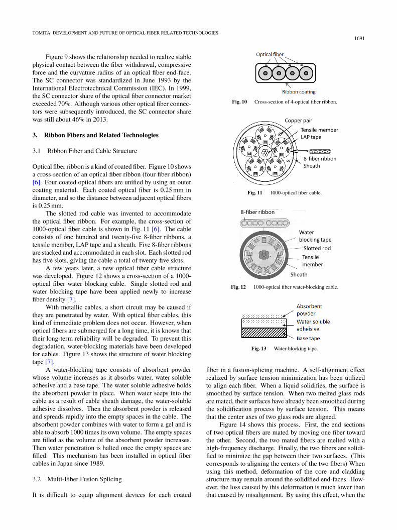
Optical fiber ribbon is a kind of coated fiber. Figure 10 showsa cross-section of an optical fiber ribbon (four fiber ribbon)[6]. Four coated optical fibers are unified by using an outercoating material. Each coated optical fiber is 0.25 mm indiameter, and so the distance between adjacent optical fibersis 0.25 mm.
The slotted rod cable was invented to accommodatethe optical fiber ribbon. For example, the cross-section of1000-optical fiber cable is shown in Fig. 11 [6]. The cableconsists of one hundred and twenty-five 8-fiber ribbons, atensile member, LAP tape and a sheath. Five 8-fiber ribbonsare stacked and accommodated in each slot. Each slotted rodhas five slots, giving the cable a total of twenty-five slots.
A few years later, a new optical fiber cable structurewas developed. Figure 12 shows a cross-section of a 1000-optical fiber water blocking cable. Single slotted rod andwater blocking tape have been applied newly to increasefiber density [7].
With metallic cables, a short circuit may be caused ifthey are penetrated by water. With optical fiber cables, thiskind of immediate problem does not occur. However, whenoptical fibers are submerged for a long time, it is known thattheir long-term reliability will be degraded. To prevent thisdegradation, water-blocking materials have been developedfor cables. Figure 13 shows the structure of water blockingtape [7].
A water-blocking tape consists of absorbent powderwhose volume increases as it absorbs water, water-solubleadhesive and a base tape. The water soluble adhesive holdsthe absorbent powder in place. When water seeps into thecable as a result of cable sheath damage, the water-solubleadhesive dissolves. Then the absorbent powder is releasedand spreads rapidly into the empty spaces in the cable. Theabsorbent powder combines with water to form a gel and isable to absorb 1000 times its own volume. The empty spacesare filled as the volume of the absorbent powder increases.Then water penetration is halted once the empty spaces arefilled. This mechanism has been installed in optical fibercables in Japan since 1989.
3.2 Multi-Fiber Fusion Splicing
It is difficult to equip alignment devices for each coated
Fig. 10 Cross-section of 4-optical fiber ribbon.
Fig. 11 1000-optical fiber cable.
Fig. 12 1000-optical fiber water-blocking cable.
Fig. 13 Water-blocking tape.
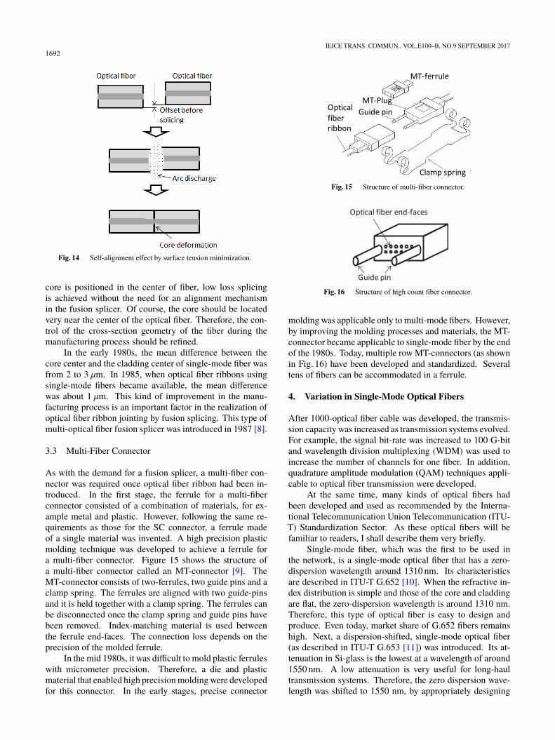
fiber in a fusion-splicing machine. A self-alignment effectrealized by surface tension minimization has been utilizedto align each fiber. When a liquid solidifies, the surface issmoothed by surface tension. When two melted glass rodsare mated, their surfaces have already been smoothed duringthe solidification process by surface tension. This meansthat the center axes of two glass rods are aligned.
Figure 14 shows this process. First, the end sectionsof two optical fibers are mated by moving one fiber towardthe other. Second, the two mated fibers are melted with ahigh-frequency discharge. Finally, the two fibers are solidi-fied to minimize the gap between their two surfaces. (Thiscorresponds to aligning the centers of the two fibers) Whenusing this method, deformation of the core and claddingstructure may remain around the solidified end-faces. How-ever, the loss caused by this deformation is much lower thanthat caused by misalignment. By using this effect, when the
1692IEICE TRANS. COMMUN., VOL.E100–B, NO.9 SEPTEMBER 2017
Fig. 14 Self-alignment effect by surface tension minimization.
core is positioned in the center of fiber, low loss splicingis achieved without the need for an alignment mechanismin the fusion splicer. Of course, the core should be locatedvery near the center of the optical fiber. Therefore, the con-trol of the cross-section geometry of the fiber during themanufacturing process should be refined.
In the early 1980s, the mean difference between thecore center and the cladding center of single-mode fiber wasfrom 2 to 3 µm. In 1985, when optical fiber ribbons usingsingle-mode fibers became available, the mean differencewas about 1 µm. This kind of improvement in the manu-facturing process is an important factor in the realization ofoptical fiber ribbon jointing by fusion splicing. This type ofmulti-optical fiber fusion splicer was introduced in 1987 [8].
3.3 Multi-Fiber Connector
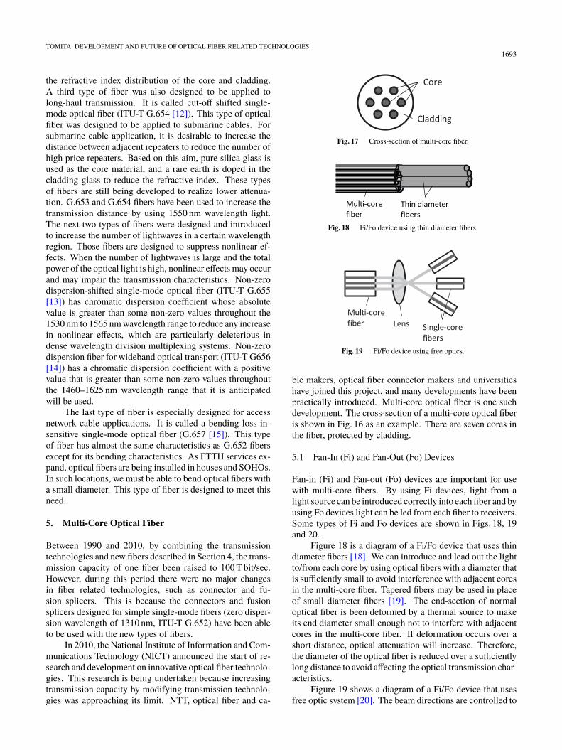
As with the demand for a fusion splicer, a multi-fiber con-nector was required once optical fiber ribbon had been in-troduced. In the first stage, the ferrule for a multi-fiberconnector consisted of a combination of materials, for ex-ample metal and plastic. However, following the same re-quirements as those for the SC connector, a ferrule madeof a single material was invented. A high precision plasticmolding technique was developed to achieve a ferrule fora multi-fiber connector. Figure 15 shows the structure ofa multi-fiber connector called an MT-connector [9]. TheMT-connector consists of two-ferrules, two guide pins and aclamp spring. The ferrules are aligned with two guide-pinsand it is held together with a clamp spring. The ferrules canbe disconnected once the clamp spring and guide pins havebeen removed. Index-matching material is used betweenthe ferrule end-faces. The connection loss depends on theprecision of the molded ferrule.
In the mid 1980s, it was difficult to mold plastic ferruleswith micrometer precision. Therefore, a die and plasticmaterial that enabled high precision molding were developedfor this connector. In the early stages, precise connector
Fig. 15 Structure of multi-fiber connector.
Fig. 16 Structure of high count fiber connector.
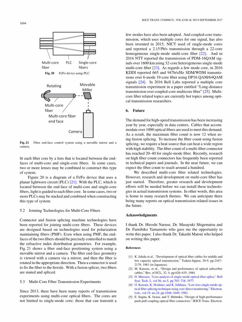
molding was applicable only to multi-mode fibers. However,by improving the molding processes and materials, the MT-connector became applicable to single-mode fiber by the endof the 1980s. Today, multiple row MT-connectors (as shownin Fig. 16) have been developed and standardized. Severaltens of fibers can be accommodated in a ferrule.
4. Variation in Single-Mode Optical Fibers
After 1000-optical fiber cable was developed, the transmis-sion capacity was increased as transmission systems evolved.For example, the signal bit-rate was increased to 100 G-bitand wavelength division multiplexing (WDM) was used toincrease the number of channels for one fiber. In addition,quadrature amplitude modulation (QAM) techniques appli-cable to optical fiber transmission were developed.
At the same time, many kinds of optical fibers hadbeen developed and used as recommended by the Interna-tional Telecommunication Union Telecommunication (ITU-T) Standardization Sector. As these optical fibers will befamiliar to readers, I shall describe them very briefly.
Single-mode fiber, which was the first to be used inthe network, is a single-mode optical fiber that has a zero-dispersion wavelength around 1310 nm. Its characteristicsare described in ITU-T G.652 [10]. When the refractive in-dex distribution is simple and those of the core and claddingare flat, the zero-dispersion wavelength is around 1310 nm.Therefore, this type of optical fiber is easy to design andproduce. Even today, market share of G.652 fibers remainshigh. Next, a dispersion-shifted, single-mode optical fiber(as described in ITU-T G.653 [11]) was introduced. Its at-tenuation in Si-glass is the lowest at a wavelength of around1550 nm. A low attenuation is very useful for long-haultransmission systems. Therefore, the zero dispersion wave-length was shifted to 1550 nm, by appropriately designing
TOMITA: DEVELOPMENT AND FUTURE OF OPTICAL FIBER RELATED TECHNOLOGIES1693
the refractive index distribution of the core and cladding.A third type of fiber was also designed to be applied tolong-haul transmission. It is called cut-off shifted single-mode optical fiber (ITU-T G.654 [12]). This type of opticalfiber was designed to be applied to submarine cables. Forsubmarine cable application, it is desirable to increase thedistance between adjacent repeaters to reduce the number ofhigh price repeaters. Based on this aim, pure silica glass isused as the core material, and a rare earth is doped in thecladding glass to reduce the refractive index. These typesof fibers are still being developed to realize lower attenua-tion. G.653 and G.654 fibers have been used to increase thetransmission distance by using 1550 nm wavelength light.The next two types of fibers were designed and introducedto increase the number of lightwaves in a certain wavelengthregion. Those fibers are designed to suppress nonlinear ef-fects. When the number of lightwaves is large and the totalpower of the optical light is high, nonlinear effects may occurand may impair the transmission characteristics. Non-zerodispersion-shifted single-mode optical fiber (ITU-T G.655[13]) has chromatic dispersion coefficient whose absolutevalue is greater than some non-zero values throughout the1530 nm to 1565 nm wavelength range to reduce any increasein nonlinear effects, which are particularly deleterious indense wavelength division multiplexing systems. Non-zerodispersion fiber for wideband optical transport (ITU-T G656[14]) has a chromatic dispersion coefficient with a positivevalue that is greater than some non-zero values throughoutthe 1460–1625 nm wavelength range that it is anticipatedwill be used.
The last type of fiber is especially designed for accessnetwork cable applications. It is called a bending-loss in-sensitive single-mode optical fiber (G.657 [15]). This typeof fiber has almost the same characteristics as G.652 fibersexcept for its bending characteristics. As FTTH services ex-pand, optical fibers are being installed in houses and SOHOs.In such locations, we must be able to bend optical fibers witha small diameter. This type of fiber is designed to meet thisneed.
5. Multi-Core Optical Fiber
Between 1990 and 2010, by combining the transmissiontechnologies and new fibers described in Section 4, the trans-mission capacity of one fiber been raised to 100 T bit/sec.However, during this period there were no major changesin fiber related technologies, such as connector and fu-sion splicers. This is because the connectors and fusionsplicers designed for simple single-mode fibers (zero disper-sion wavelength of 1310 nm, ITU-T G.652) have been ableto be used with the new types of fibers.
In 2010, the National Institute of Information and Com-munications Technology (NICT) announced the start of re-search and development on innovative optical fiber technolo-gies. This research is being undertaken because increasingtransmission capacity by modifying transmission technolo-gies was approaching its limit. NTT, optical fiber and ca-
Fig. 17 Cross-section of multi-core fiber.
Fig. 18 Fi/Fo device using thin diameter fibers.
Fig. 19 Fi/Fo device using free optics.
ble makers, optical fiber connector makers and universitieshave joined this project, and many developments have beenpractically introduced. Multi-core optical fiber is one suchdevelopment. The cross-section of a multi-core optical fiberis shown in Fig. 16 as an example. There are seven cores inthe fiber, protected by cladding.
5.1 Fan-In (Fi) and Fan-Out (Fo) Devices
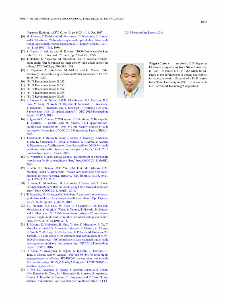
Fan-in (Fi) and Fan-out (Fo) devices are important for usewith multi-core fibers. By using Fi devices, light from alight source can be introduced correctly into each fiber and byusing Fo devices light can be led from each fiber to receivers.Some types of Fi and Fo devices are shown in Figs. 18, 19and 20.
Figure 18 is a diagram of a Fi/Fo device that uses thindiameter fibers [18]. We can introduce and lead out the lightto/from each core by using optical fibers with a diameter thatis sufficiently small to avoid interference with adjacent coresin the multi-core fiber. Tapered fibers may be used in placeof small diameter fibers [19]. The end-section of normaloptical fiber is been deformed by a thermal source to makeits end diameter small enough not to interfere with adjacentcores in the multi-core fiber. If deformation occurs over ashort distance, optical attenuation will increase. Therefore,the diameter of the optical fiber is reduced over a sufficientlylong distance to avoid affecting the optical transmission char-acteristics.
Figure 19 shows a diagram of a Fi/Fo device that usesfree optic system [20]. The beam directions are controlled to
1694IEICE TRANS. COMMUN., VOL.E100–B, NO.9 SEPTEMBER 2017
Fig. 20 Fi/Fo device using PLC.
Fig. 21 Fiber end-face control system using a movable mirror and acamera.
fit each fiber core by a lens that is located between the end-faces of multi-core and single-core fibers. In some cases,two or more lenses may be combined to construct this typeof system.
Figure 20 is a diagram of a Fi/Fo device that uses aplanar lightwave circuit (PLC) [21]. With the PLC, which islocated between the end-face of multi-core and single-corefibers, light is guided to each fiber core. In some cases, two ormore PLCs may be stacked and combined when constructingthis type of system.
5.2 Jointing Technologies for Multi-Core Fibers
Connector and fusion splicing machine technologies havebeen reported for joining multi-core fibers. These devicesare designed based on technologies used for polarizationmaintaining fibers (PMF). Even when using PMF, the end-faces of the two fibers should be precisely controlled to matchthe refractive index distribution geometries. For example,Fig. 21 shows a fiber end-face positioning system using amovable mirror and a camera. The fiber end-face geometryis viewed with a camera via a mirror, and then the fiber isrotated in the appropriate direction. Then a connector is usedto fix the fiber to the ferrule. With a fusion splicer, two fibersare mated and spliced.
5.3 Multi-Core Fiber Transmission Experiments
Since 2013, there have been many reports of transmissionexperiments using multi-core optical fibers. The cores arenot limited to single-mode core; those that can transmit a
few modes have also been adopted. And coupled-core trans-mission, which uses multiple cores for one signal, has alsobeen invented in 2015, NICT used of single-mode coresand reported a 2.15 Pb/s transmission through a 22-corehomogeneous single-mode multi-core fiber [22]. And in2016 NTT reported the transmission of PDM-16QAM sig-nals over 1600 km using 32-core heterogeneous single-modemulti-core fiber [23]. As regards a few mode core, in 2016KDDI reported 665 and 947b/s/Hz SDM/WDM transmis-sions over 6-mode 19-core fiber using DP16 QAM/64QAMsignals [24]. In 2016 Bell Labs reported a multiple coretransmission experiment in a paper entitled “Long-distancetransmission over coupled-core multicore fiber” [25]. Multi-core fiber related topics are currently hot topics among opti-cal transmission researchers.
6. Future
The demand for high-speed transmission has been increasingyear by year, especially in data centers. Cables that accom-modate over 1000 optical fibers are used to meet this demand.As a result, the maximum fiber count is now 12 when us-ing fusion splicing. To increase the fiber count using fusionsplicing, we require a heat source that can heat a wide regionwith high stability. The fiber count of a multi-fiber connectorhas reached 20–40 for single-mode fiber. Recently, researchon high fiber count connectors has frequently been reportedin technical papers and journals. In the near future, we canexpect the fiber count to reach around a hundred.
We described multi-core fiber related technologies.However, research and development on multi-core fiber hasjust started. Therefore, greater research and developmentefforts will be needed before we can install these technolo-gies in actual transmission systems. In other words, this areais home to many research themes. We can anticipate therebeing many reports on optical transmission related issues inthe future.
Acknowledgments
I thank Dr. Hiroshi Naruse, Dr. Masayuki Shigematsu andDr. Fumihiko Yamamoto who gave me the opportunity towrite this paper. I also thank Dr. Takashi Matsui who helpedon writing this paper.
References
[1] K. Ishida et al., “Development of optical fiber cables for middle andlow capacity optical transmission,” Tsuken-Jippou, 30-9, pp.2167–2179, 1981 (in Japanese).
[2] M. Kawase, et al., “Design and performance of optical subscribercables,” Rev. of ECL, 32, 4, pp.626–635, 1984.
[3] D. Marcuse, “Loss analysis of single-mode optical fiber splice,” BellSyst. Tech. J., vol.56, no.5, pp.703–718, 1977.
[4] O. Kawata, K. Hoshino, and K. Ishihara, “Low-loss single-mode op-tical fiber splicing technique using core direct monitoring,” Electron.Lett., vol.19, no.24, pp.1048–1049, 1983.
[5] E. Sugita, K. Iwasa, and T. Shintaku, “Design of high-performancepush-pull coupling optical fibre connectors,” IEICE Trans. Electron.
TOMITA: DEVELOPMENT AND FUTURE OF OPTICAL FIBER RELATED TECHNOLOGIES1695
(Japanese Edition), vol.J70-C, no.10, pp.1405–1414, Oct. 1987.[6] M. Kawase, T. Fuchigami, M. Matsumoto, S. Nagasawa, S. Tomita,
and S. Takashima, “Subscriber single-mode optical fiber ribbon cabletechnologies suitable for midspan access,” J. Lightw. Technol., vol.7,no.11, pp.1965–1681, 1989.
[7] S. Tomita, F. Ashiya, and M. Kawase, “1000-fiber water-blockingcable,” IEICE Trans., vol.E73, no.9, pp.1511–1516, 1990.
[8] T. Haibara, S. Nagasawa, M. Matsumoto, and K. Kawase, “Single-mode multi-fiber technique for high density high-count subscribercables,” 37th IWCS, pp.576–585, 1988.
[9] S. Nagasawa, H. Furukawa, M. Makita, and H. Murata, “Me-chanically transferable single-mode multifiber connector,” OEC’89,pp.48–49, 1989.
[10] ITU-T Recommendation G.652.[11] ITU-T Recommendation G.653.[12] ITU-T Recommendation G.654.[13] ITU-T Recommendation G.655.[14] ITU-T Recommendation G.656.[15] J. Sakaguchi, W. Klaus, J.M.D. Mendinueta, B.J. Puttnam, R.S.
Luis, Y. Awaji, N. Wada, T. Hayashi, T. Nakanishi, T. Watanabe,Y. Kokubun, T. Takahata, and T. Kobayashi, “Realizing a 36-core,3-mode fiber with 108 spatial channels,” OFC 2015 PostdeadlinePapers, Th5C.2, 2015.
[16] K. Igarashi, D. Souma, Y. Wakayama, K. Takeshima, Y. Kawaguchi,T. Tsuritani, I. Morita, and M. Suzuki, “114 space-division-multiplexed transmission over 9.8-km weakly-coupled-6-modeuncoupled-19-core fibers,” OFC 2015 Postdeadline Papers, Th5C.4,2015.
[17] T. Sakamoto, T. Matsui, K. Saitoh, S. Saitoh, K. Takenaga, T. Mizuno,Y. abe, K. Shibahara, Y. Tobita, S. Matsuo, K. Aikawa, S. Aozasa,K. Nakajima, and Y. Miyamoto, “Low-loss and low-DMD few-modemulti-core fiber with highest core multiplicity factor,” OFC 2015Postdeadline Papers, Th5A.4, 2015.
[18] K. Watanabe, T. Saito, and M. Shiino, “Development of fiber bundletype fan-out for 19-core multicore fiber,” Proc. OECC 2014, Mo1E2,2014.
[19] B. Zhu, T.F. Taunay, M.F. Yan, J.M. Fini, M. Fishteyn, E.M.Monberg, and F.V. Dimarcello, “Seven-core multicore fiber trans-missions for passive optical network,” Opt. Express, vol.18, no.11,pp.11117–11122, 2010.
[20] H. Arao, O. Shimakawa, M. Harumoto, T. Sano, and A. Inoue,“Compact multi-core fiber fan-in/out using GRIN lens and microlensarray,” Proc. OECC 2014, Mo1E1, 2014.
[21] T. Watanabe, M. Hikita, and Y. Kokubun, “Laminated polymer wave-guide fan-out device for uncoupled multi-core fibers,” Opt. Express,vol.20, no.24, pp.26317–26325, 2012.
[22] B.J. Puttnam, R.S. Luís, W. Klaus, J. Sakaguchi, J.-M. DelgadoMendinueta, Y. Awaji, N. Wada, Y. Tamura, T. Hayashi, M. Hirano,and J. Marciante, “2.15 Pb/s transmission using a 22 core homo-geneous single-mode multi-core fiber and wideband optical comb,”Proc. ECOC 2015, no.1056, 2015.
[23] T. Mizuno, K. Shibahara, H. Ono, Y. abe, Y. Miyamoto, F. Ye, T.Morioka, Y. Sasaki, Y. Amma, K. Takenaga, S. Matsuo, K. Aikawa,K. Saitoh, Y.-M. Jung, D.J. Richardson, K. Pulverer, M. Bohn, and M.Yamada, “32-core dense SDM unidirectional transmission of PDM-16QAM signals over 1600 km using crosstalk-managed single-modeheterogeneous multicore transmission line,” OFC 2016 PostdeadlinePapers, Th5C.3, 2016.
[24] D. Soma, Y. Wakayama, S. Beppu, K. Igarashi, T. Tsuritani, H.Taga, I. Morita, and M. Suzuki, “665 and 947 b/s/Hz ultra-highlyaggregate-spectral-efficient SDM/WDM transmission over 6-mode19-core fibre using DP-16QAM/64QAM signals,” ECOC 2016 Post-deadline Papers, 2016.
[25] R. Ryf, J.C. Alvarado, B. Huang, J. Antonio-Lopez, S.H. Chang,N.K. Fontaine, H. Chen, R.-J. Essiambre, E. Burrows, R. Amezcua-Correa, T. Hayashi, Y. Tamura, T. Hasegawa, and T. Taru, “Long-distance transmission over coupled-core multicore fiber,” ECOC
2016 Postdeadline Papers, 2016.
Shigeru Tomita received a B.S. degree inElectronics Engineering from Nihon Universityin 1983. He jointed NTT in 1983 where he en-gaged in the development of optical fiber cablesfor access networks. He received a Ph.D degreefrom Nihon University in 1997. He is now withNTT Advanced Technology Corporation.