Embed Size (px)
Citation preview
Shyamshankar.M.B Int. Journal of Engineering Research and Applications www.ijera.com
ISSN : 2248-9622, Vol. 5, Issue 5, ( Part -6) May 2015, pp.164-172
www.ijera.com 164 | P a g e
Investigation on Divergent Exit Curvature Effect on Nozzle
Pressure Ratio of Supersonic Convergent Divergent Nozzle
Shyamshankar.M.B*, Sankar.V** *(Department of Aeronautical Engineering, Anna University, Chennai)
** (Department of Aeronautical Engineering, Anna University, Chennai)
ABSTRACT The objective of this project work is to computationally analyze shock waves in the Convergent Divergent (CD)
Nozzle. The commercial CFD code Fluent is employed to analyze the compressible flow through the nozzle.
The analysis is about NPR (Nozzle Pressure Ratio) i.e., the ratio between exit pressure of the nozzle to ambient
pressure. The various models of CD Nozzle are designed and the results are compared. The flow characteristic
of shockwave for various design of CD Nozzle is also discussed. The purpose of this project is to investigate
supersonic C-D nozzle flow for increasing NPR (Nozzle pressure ratio) through CFD. The imperfect matching
between the pressures and ambient pressure and exit pressure leads to the formation of a complicated shock
wave structure. Supersonic nozzle flow separation occurs in CD nozzles at NPR values far above their design
value that results in shock formation inside the nozzle.
The one-dimensional analysis approximations are not accurate, in reality the flow detaches from the wall and
forms a separation region, subsequently the flow downstream becomes non-uniform and unstable. Shock wave
affects flow performance of nozzle from NPR value 1.63 for existing geometrical conditions of nozzle. Problem
of using this nozzle above 1.63NPR is shock wave at downstream of throat. After shock wave, static pressure
increases further downstream of flow. It leads to flow separation and back pressure effects. Back pressure makes
nozzle chocked. To investigate this problem, geometry of divergent portion is introduced and analysed through
CFD. This is expected in resulting of reduction of flow separation and back pressure effect as well as increase in
nozzle working NPR.
Keywords - circular cut-out, elliptical cut-outs, failure load, flat composite panel, mesh size.
I. INTRODUCTION Convergent nozzles accelerate subsonic fluids. If
the nozzle pressure ratio is high enough, then the
flow will reach sonic velocity at the narrowest point
(i.e. the nozzle throat). In this situation, the nozzle is
said to be choked. Increasing the nozzle pressure
ratio further will not increase the throat Mach
number above one. Downstream (i.e. external to the
nozzle) the flow is free to expand to supersonic
velocities; however Mach 1 can be a very high speed
for a hot gas because the speed of sound varies as the
square root of absolute temperature. This fact is used
extensively in rocketry where hypersonic flows are
required and where propellant mixtures are
deliberately chosen to further increase the sonic
speed.
A nozzle is often a pipe or tube of varying cross
sectional area and it can be used to direct or modify
the flow of a fluid (liquid or gas). Nozzles are
frequently used to control the rate of flow, speed,
direction, mass, shape, and/or the pressure of the
stream that emerges from them. In nozzle, velocity of
fluid increases on the expense of its pressure energy.
A nozzle is a device designed to control the
direction or characteristics of a fluid flow (especially
to increase velocity) as it exits (or enters) an enclosed
chamber or pipe. A gas jet, fluid jet, or hydro jet is a
nozzle intended to eject gas or fluid in a coherent
stream into a surrounding medium. Gas jets are
commonly found in gas stoves, ovens, or barbecues.
Gas jets were commonly used for light before the
development of electric light. Other types of fluid jets
are found in carburettors, where smooth calibrated
orifices are used to regulate the flow of fuel into an
engine, and in spas. Another specialized jet is
the laminar jet. This is a water jet that contains
devices to smooth out the pressure and flow, and
gives laminar flow, as its name suggests. This gives
better results for fountains.
Nozzles used for feeding hot blast into a blast
furnace or forge are called tubers. Jet nozzles are also
use in large rooms where the distribution of air via
ceiling diffusers is not possible or not practical.
Diffusers that use jet nozzles are called jet diffuser
where it will be arranged in the side wall areas in
order to distribute air. When the temperature
difference between the supply air and the room air
changes, the supply air stream is deflected upwards to
supply warm air or deflected downwards to supply
cold air.
Frequently, the goal is to increase the kinetic
energy of the flowing medium at the expense of
RESEARCH ARTICLE OPEN ACCESS
Shyamshankar.M.B Int. Journal of Engineering Research and Applications www.ijera.com
ISSN : 2248-9622, Vol. 5, Issue 5, ( Part -6) May 2015, pp.164-172
www.ijera.com 165 | P a g e
its pressure and internal energy. Nozzles can be
described as convergent (narrowing down from a
wide diameter to a smaller diameter in the direction
of the flow) or divergent (expanding from a smaller
diameter to a larger one). A de Laval nozzle has a
convergent section followed by a divergent section
and is often called a convergent-divergent nozzle.
II. LITERATURE SURVEY Blom Martina has given numerical investigation
of 3d compressible duct flow a generic supersonic
bump in a duct has been studied. The shock wave
over the bump is accelerated, inducing a shock wave
in the downstream, interacting with the wall
boundary layer and triggering boundary layer
separation.
Gustavo Bono et. al presented an adaptive mesh
strategy based on nodal re-allocation is presented in
this work. This technique is applied to problems
involving compressible flows with strong shocks
waves, improving the accuracy and efficiency of the
numerical solution. The initial mesh is continuously
adapted during the solution process keeping, as much
as possible, mesh smoothness and local orthogonality
using an unconstrained nonlinear optimization
method. The adaptive procedure, which is coupled to
an edge-based error estimate aiming to equi-
distribute the error over the cell edges is the main
contribution of this work. The flow is simulated using
the Finite Element Method (FEM) with an explicit
one-step Taylor- Galerkin scheme, in which an
Arbitrary Lagrangean-Eulerian (ALE) description is
employed to take into account mesh movement.
Finally, to demonstrate the capabilities of the
adaptive process, several examples of compressible
in-viscid flows are presented.
III. DESIGN OF CD-NOZZLE Step 1: Inlet Pressure – 17 bar
Exit Pressure – 1.01325 bar (It is nothing but
pressure of medium where fluid is going to deliver)
Inlet Temperature – 473K
Mass Flow - 32 Kg/s
Fluid - Air
Step 2: P* / P1 = (2/ᵞ + 1) ᵞ/ (ᵞ-1)
ᵞ - 1.4 is polytrophic index for air
P* - Throat Pressure – 9.23 bar
Step 3: T* / T1 = (2 /ᵞ + 1)
T* - Throat temperature - 393.78 K
Step 4: Density (throat) = P* / R T
*
= 8.08 Kg / m3
Step 5: V* Throat Velocity = (ᵞRT
*)
½
= 396.65 m/s
Step 6: A* Throat Area = mass flow rate / throat
density * V*
= 0.00997 m2
D* throat diameter = 113 mm
Step 7: T1 / T2 (Exit Temperature) = (P1 / P2 (exit
pressure)) (ᵞ-1) /
ᵞ
T2 = 210 K
Step 8: Density2 = P2 / R T2
= 1.7 Kg / m3
Step 9: V2 = 44.72 * (Cp [T1- T2])
= 726 m/s
Step 10: A2 = mass flow rate / Density2 * V2
= 0.049 m2
D2 = 183.3 mm
Step 11: Length of divergent nozzle = (D2 – D*) / 2 *
tan αd
= 105.57 mm
αd – Divergent angle = 18°
Step 12: Length of convergent nozzle = (d1- d*)/ 2 *
tan αc
= 57.94 mm
αc – Convergent angle = 13°
Fig. 1 Original Nozzle
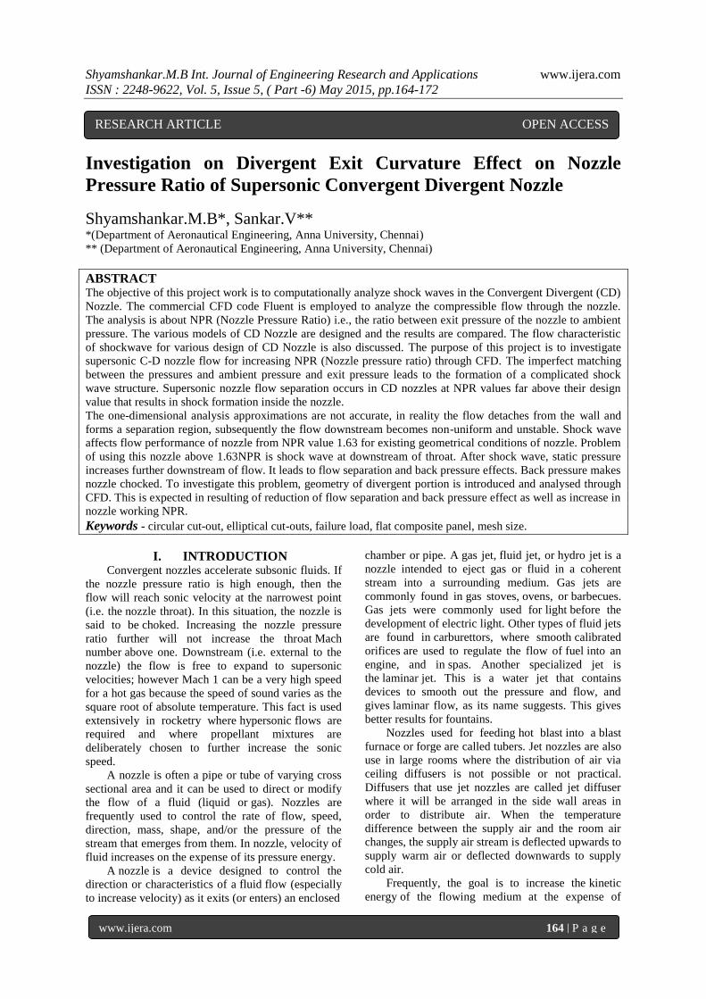
Modified nozzle dimensions are presented
below. Convergence portion diameter at end is varied
by percentage of outlet diameter.
Fig. 2 Modified Nozzle
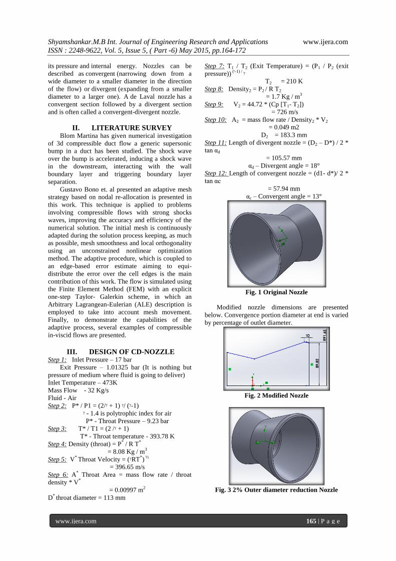
Fig. 3 2% Outer diameter reduction Nozzle
Shyamshankar.M.B Int. Journal of Engineering Research and Applications www.ijera.com
ISSN : 2248-9622, Vol. 5, Issue 5, ( Part -6) May 2015, pp.164-172
www.ijera.com 166 | P a g e
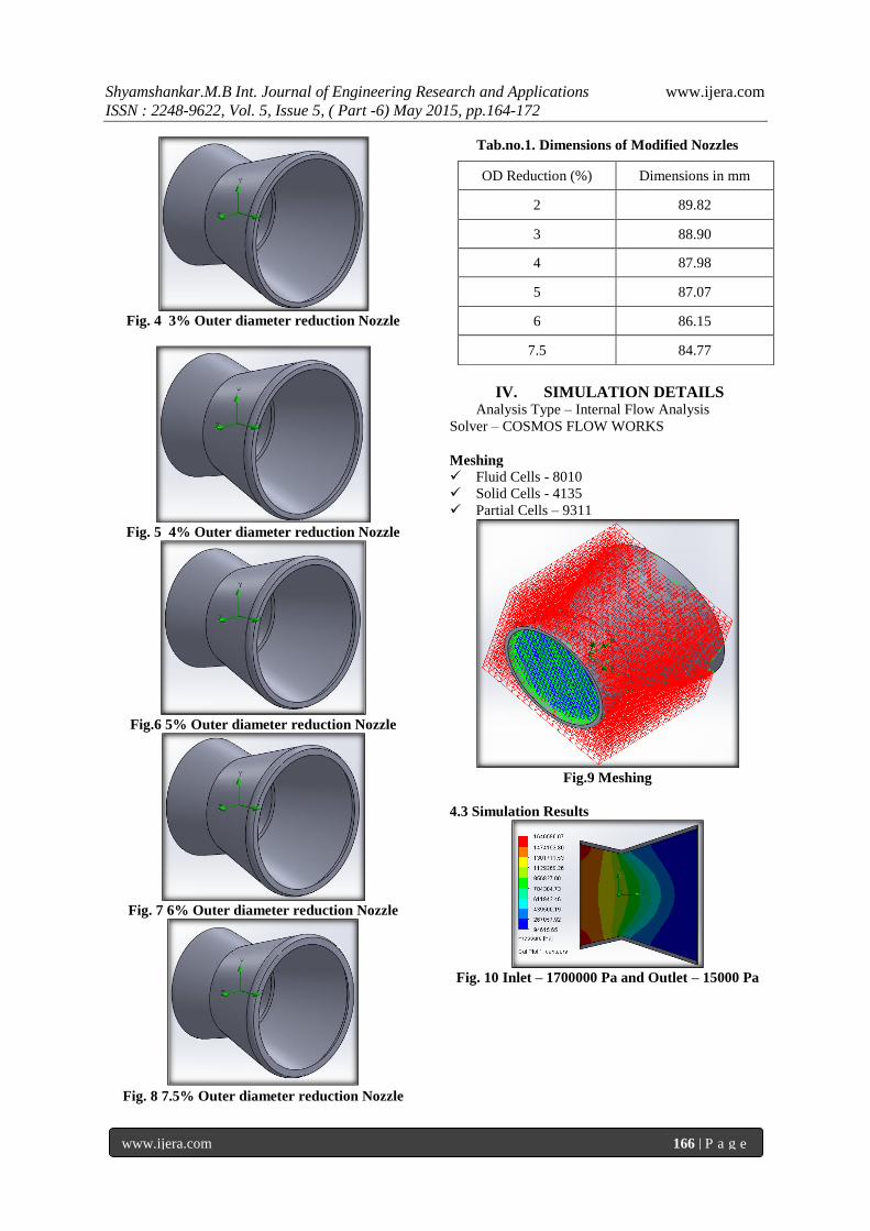
Fig. 4 3% Outer diameter reduction Nozzle
Fig. 5 4% Outer diameter reduction Nozzle
Fig.6 5% Outer diameter reduction Nozzle
Fig. 7 6% Outer diameter reduction Nozzle
Fig. 8 7.5% Outer diameter reduction Nozzle
Tab.no.1. Dimensions of Modified Nozzles
IV. SIMULATION DETAILS Analysis Type – Internal Flow Analysis
Solver – COSMOS FLOW WORKS
Meshing
Fluid Cells - 8010
Solid Cells - 4135
Partial Cells – 9311
Fig.9 Meshing
4.3 Simulation Results
Fig. 10 Inlet – 1700000 Pa and Outlet – 15000 Pa
OD Reduction (%) Dimensions in mm
2 89.82
3 88.90
4 87.98
5 87.07
6 86.15
7.5 84.77
Shyamshankar.M.B Int. Journal of Engineering Research and Applications www.ijera.com
ISSN : 2248-9622, Vol. 5, Issue 5, ( Part -6) May 2015, pp.164-172
www.ijera.com 167 | P a g e
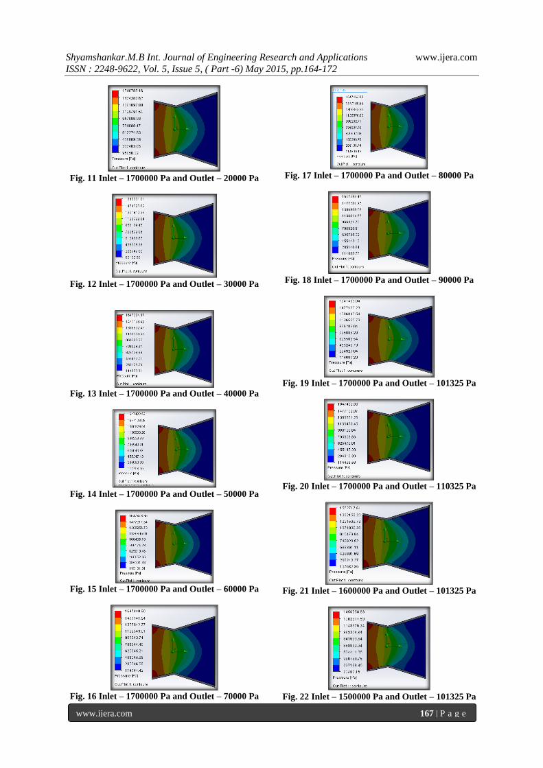
Fig. 11 Inlet – 1700000 Pa and Outlet – 20000 Pa
Fig. 12 Inlet – 1700000 Pa and Outlet – 30000 Pa
Fig. 13 Inlet – 1700000 Pa and Outlet – 40000 Pa
Fig. 14 Inlet – 1700000 Pa and Outlet – 50000 Pa
Fig. 15 Inlet – 1700000 Pa and Outlet – 60000 Pa
Fig. 16 Inlet – 1700000 Pa and Outlet – 70000 Pa
Fig. 17 Inlet – 1700000 Pa and Outlet – 80000 Pa
Fig. 18 Inlet – 1700000 Pa and Outlet – 90000 Pa
Fig. 19 Inlet – 1700000 Pa and Outlet – 101325 Pa
Fig. 20 Inlet – 1700000 Pa and Outlet – 110325 Pa
Fig. 21 Inlet – 1600000 Pa and Outlet – 101325 Pa
Fig. 22 Inlet – 1500000 Pa and Outlet – 101325 Pa
Shyamshankar.M.B Int. Journal of Engineering Research and Applications www.ijera.com
ISSN : 2248-9622, Vol. 5, Issue 5, ( Part -6) May 2015, pp.164-172
www.ijera.com 168 | P a g e
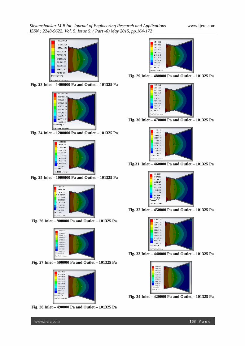
Fig. 23 Inlet – 1400000 Pa and Outlet – 101325 Pa
Fig. 24 Inlet – 1200000 Pa and Outlet – 101325 Pa
Fig. 25 Inlet – 1000000 Pa and Outlet – 101325 Pa
Fig. 26 Inlet – 900000 Pa and Outlet – 101325 Pa
Fig. 27 Inlet – 500000 Pa and Outlet – 101325 Pa
Fig. 28 Inlet – 490000 Pa and Outlet – 101325 Pa
Fig. 29 Inlet – 480000 Pa and Outlet – 101325 Pa
Fig. 30 Inlet – 470000 Pa and Outlet – 101325 Pa
Fig.31 Inlet – 460000 Pa and Outlet – 101325 Pa
Fig. 32 Inlet – 450000 Pa and Outlet – 101325 Pa
Fig. 33 Inlet – 440000 Pa and Outlet – 101325 Pa
Fig. 34 Inlet – 420000 Pa and Outlet – 101325 Pa
Shyamshankar.M.B Int. Journal of Engineering Research and Applications www.ijera.com
ISSN : 2248-9622, Vol. 5, Issue 5, ( Part -6) May 2015, pp.164-172
www.ijera.com 169 | P a g e
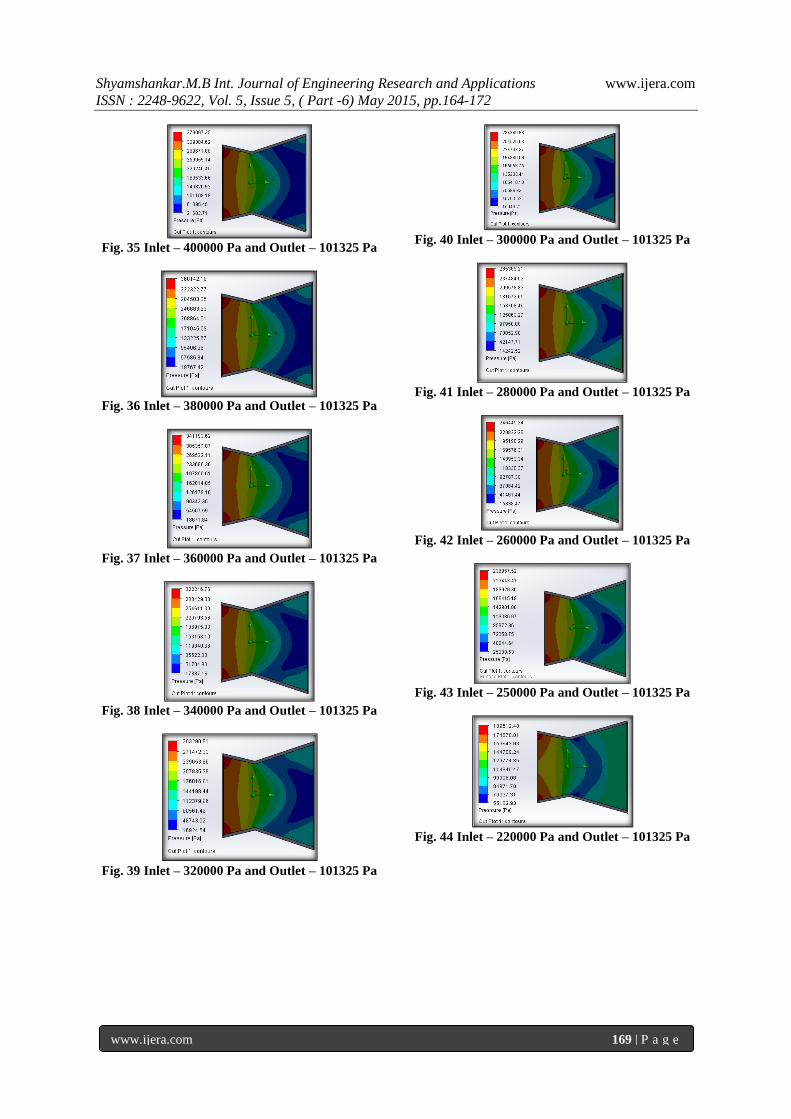
Fig. 35 Inlet – 400000 Pa and Outlet – 101325 Pa
Fig. 36 Inlet – 380000 Pa and Outlet – 101325 Pa
Fig. 37 Inlet – 360000 Pa and Outlet – 101325 Pa
Fig. 38 Inlet – 340000 Pa and Outlet – 101325 Pa
Fig. 39 Inlet – 320000 Pa and Outlet – 101325 Pa
Fig. 40 Inlet – 300000 Pa and Outlet – 101325 Pa
Fig. 41 Inlet – 280000 Pa and Outlet – 101325 Pa
Fig. 42 Inlet – 260000 Pa and Outlet – 101325 Pa
Fig. 43 Inlet – 250000 Pa and Outlet – 101325 Pa
Fig. 44 Inlet – 220000 Pa and Outlet – 101325 Pa
Shyamshankar.M.B Int. Journal of Engineering Research and Applications www.ijera.com
ISSN : 2248-9622, Vol. 5, Issue 5, ( Part -6) May 2015, pp.164-172
www.ijera.com 170 | P a g e
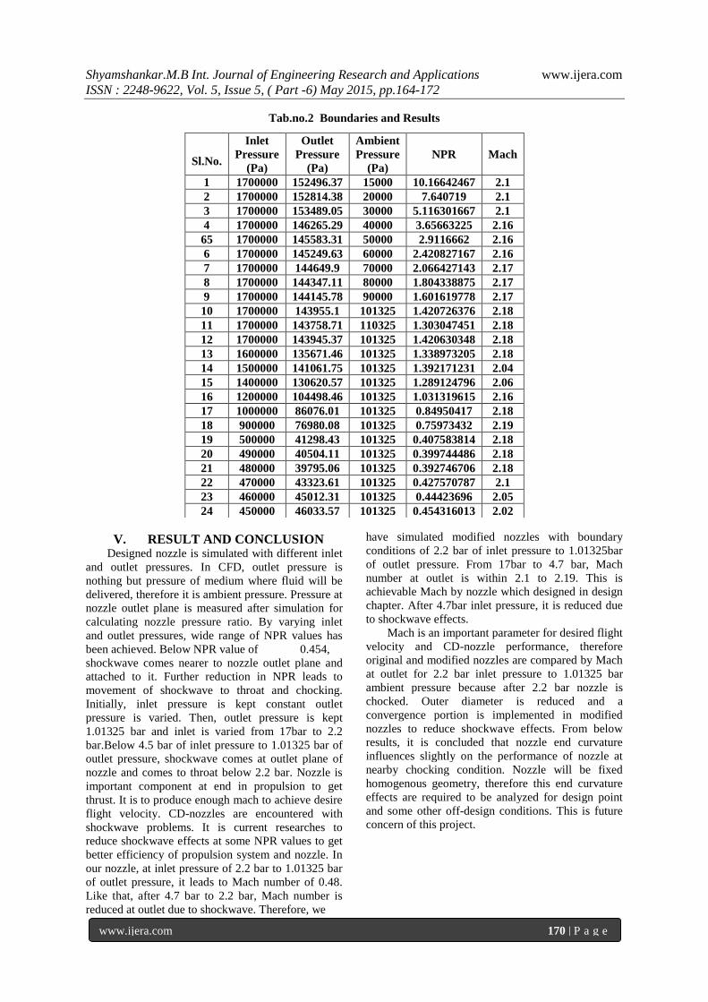
Tab.no.2 Boundaries and Results
V. RESULT AND CONCLUSION Designed nozzle is simulated with different inlet
and outlet pressures. In CFD, outlet pressure is
nothing but pressure of medium where fluid will be
delivered, therefore it is ambient pressure. Pressure at
nozzle outlet plane is measured after simulation for
calculating nozzle pressure ratio. By varying inlet
and outlet pressures, wide range of NPR values has
been achieved. Below NPR value of 0.454,
shockwave comes nearer to nozzle outlet plane and
attached to it. Further reduction in NPR leads to
movement of shockwave to throat and chocking.
Initially, inlet pressure is kept constant outlet
pressure is varied. Then, outlet pressure is kept
1.01325 bar and inlet is varied from 17bar to 2.2
bar.Below 4.5 bar of inlet pressure to 1.01325 bar of
outlet pressure, shockwave comes at outlet plane of
nozzle and comes to throat below 2.2 bar. Nozzle is
important component at end in propulsion to get
thrust. It is to produce enough mach to achieve desire
flight velocity. CD-nozzles are encountered with
shockwave problems. It is current researches to
reduce shockwave effects at some NPR values to get
better efficiency of propulsion system and nozzle. In
our nozzle, at inlet pressure of 2.2 bar to 1.01325 bar
of outlet pressure, it leads to Mach number of 0.48.
Like that, after 4.7 bar to 2.2 bar, Mach number is
reduced at outlet due to shockwave. Therefore, we
have simulated modified nozzles with boundary
conditions of 2.2 bar of inlet pressure to 1.01325bar
of outlet pressure. From 17bar to 4.7 bar, Mach
number at outlet is within 2.1 to 2.19. This is
achievable Mach by nozzle which designed in design
chapter. After 4.7bar inlet pressure, it is reduced due
to shockwave effects.
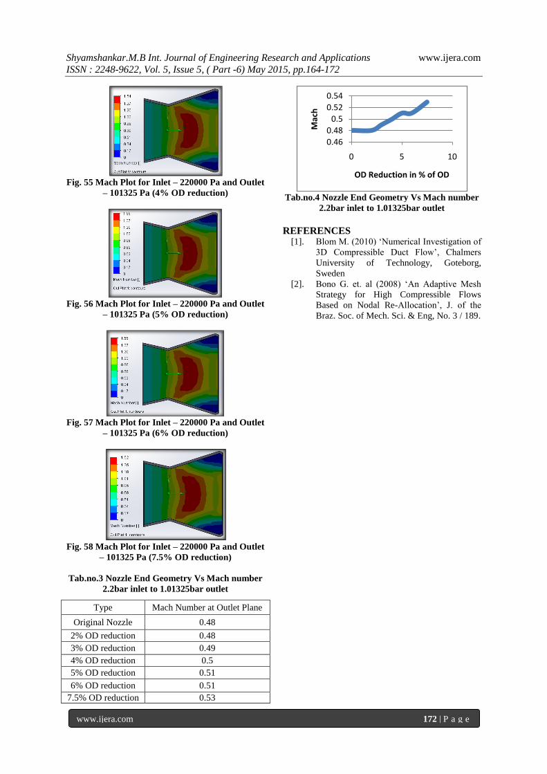
Mach is an important parameter for desired flight
velocity and CD-nozzle performance, therefore
original and modified nozzles are compared by Mach
at outlet for 2.2 bar inlet pressure to 1.01325 bar
ambient pressure because after 2.2 bar nozzle is
chocked. Outer diameter is reduced and a
convergence portion is implemented in modified
nozzles to reduce shockwave effects. From below
results, it is concluded that nozzle end curvature
influences slightly on the performance of nozzle at
nearby chocking condition. Nozzle will be fixed
homogenous geometry, therefore this end curvature
effects are required to be analyzed for design point
and some other off-design conditions. This is future
concern of this project.
Sl.No.
Inlet
Pressure
(Pa)
Outlet
Pressure
(Pa)
Ambient
Pressure
(Pa)
NPR Mach
1 1700000 152496.37 15000 10.16642467 2.1
2 1700000 152814.38 20000 7.640719 2.1
3 1700000 153489.05 30000 5.116301667 2.1
4 1700000 146265.29 40000 3.65663225 2.16
65 1700000 145583.31 50000 2.9116662 2.16
6 1700000 145249.63 60000 2.420827167 2.16
7 1700000 144649.9 70000 2.066427143 2.17
8 1700000 144347.11 80000 1.804338875 2.17
9 1700000 144145.78 90000 1.601619778 2.17
10 1700000 143955.1 101325 1.420726376 2.18
11 1700000 143758.71 110325 1.303047451 2.18
12 1700000 143945.37 101325 1.420630348 2.18
13 1600000 135671.46 101325 1.338973205 2.18
14 1500000 141061.75 101325 1.392171231 2.04
15 1400000 130620.57 101325 1.289124796 2.06
16 1200000 104498.46 101325 1.031319615 2.16
17 1000000 86076.01 101325 0.84950417 2.18
18 900000 76980.08 101325 0.75973432 2.19
19 500000 41298.43 101325 0.407583814 2.18
20 490000 40504.11 101325 0.399744486 2.18
21 480000 39795.06 101325 0.392746706 2.18
22 470000 43323.61 101325 0.427570787 2.1
23 460000 45012.31 101325 0.44423696 2.05
24 450000 46033.57 101325 0.454316013 2.02
Shyamshankar.M.B Int. Journal of Engineering Research and Applications www.ijera.com
ISSN : 2248-9622, Vol. 5, Issue 5, ( Part -6) May 2015, pp.164-172
www.ijera.com 171 | P a g e
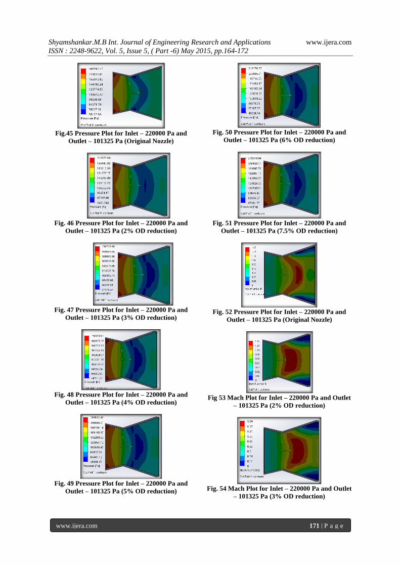
Fig.45 Pressure Plot for Inlet – 220000 Pa and
Outlet – 101325 Pa (Original Nozzle)
Fig. 46 Pressure Plot for Inlet – 220000 Pa and
Outlet – 101325 Pa (2% OD reduction)
Fig. 47 Pressure Plot for Inlet – 220000 Pa and
Outlet – 101325 Pa (3% OD reduction)
Fig. 48 Pressure Plot for Inlet – 220000 Pa and
Outlet – 101325 Pa (4% OD reduction)
Fig. 49 Pressure Plot for Inlet – 220000 Pa and
Outlet – 101325 Pa (5% OD reduction)
Fig. 50 Pressure Plot for Inlet – 220000 Pa and
Outlet – 101325 Pa (6% OD reduction)
Fig. 51 Pressure Plot for Inlet – 220000 Pa and
Outlet – 101325 Pa (7.5% OD reduction)
Fig. 52 Pressure Plot for Inlet – 220000 Pa and
Outlet – 101325 Pa (Original Nozzle)
Fig 53 Mach Plot for Inlet – 220000 Pa and Outlet
– 101325 Pa (2% OD reduction)
Fig. 54 Mach Plot for Inlet – 220000 Pa and Outlet
– 101325 Pa (3% OD reduction)
Shyamshankar.M.B Int. Journal of Engineering Research and Applications www.ijera.com
ISSN : 2248-9622, Vol. 5, Issue 5, ( Part -6) May 2015, pp.164-172
www.ijera.com 172 | P a g e
Fig. 55 Mach Plot for Inlet – 220000 Pa and Outlet
– 101325 Pa (4% OD reduction)
Fig. 56 Mach Plot for Inlet – 220000 Pa and Outlet
– 101325 Pa (5% OD reduction)
Fig. 57 Mach Plot for Inlet – 220000 Pa and Outlet
– 101325 Pa (6% OD reduction)
Fig. 58 Mach Plot for Inlet – 220000 Pa and Outlet
– 101325 Pa (7.5% OD reduction)
Tab.no.3 Nozzle End Geometry Vs Mach number
2.2bar inlet to 1.01325bar outlet
Tab.no.4 Nozzle End Geometry Vs Mach number
2.2bar inlet to 1.01325bar outlet
REFERENCES [1]. Blom M. (2010) ‘Numerical Investigation of
3D Compressible Duct Flow’, Chalmers
University of Technology, Goteborg,
Sweden
[2]. Bono G. et. al (2008) ‘An Adaptive Mesh
Strategy for High Compressible Flows
Based on Nodal Re-Allocation’, J. of the
Braz. Soc. of Mech. Sci. & Eng, No. 3 / 189.
0.46
0.48
0.5
0.52
0.54
0 5 10
Mac
h
OD Reduction in % of OD
Type Mach Number at Outlet Plane
Original Nozzle 0.48
2% OD reduction 0.48
3% OD reduction 0.49
4% OD reduction 0.5
5% OD reduction 0.51
6% OD reduction 0.51
7.5% OD reduction 0.53