Embed Size (px)
Citation preview

Open Journal of Fluid Dynamics 2013 3 69-74 httpdxdoiorg104236ojfd201332A011 Published Online July 2013 (httpwwwscirporgjournalojfd)
Effects of Nozzle-Lip Length on Reduction of Transonic Resonance in 2D Supersonic Nozzle
Seoungyoung Shin Akira Matsunaga Hiroyuki Marubayashi Toshiyuki Aoki Department of Energy and Environmental Engineering Kyhu University Fukuoka Japan
Email shszerogmailcom
Received May 28 2013 revised June 5 2013 accepted June 12 2013
Copyright copy 2013 Seoungyoung Shin et al This is an open access article distributed under the Creative Commons Attribution Li- cense which permits unrestricted use distribution and reproduction in any medium provided the original work is properly cited
ABSTRACT
It is known that the transonic resonance takes place in divergent section of supersonic nozzle similarly to the longitu- dinal acoustic resonance of a conical section with one end closed and the other end open And the ldquoconical sectionrdquo is similar to the separation zone between shock wave and nozzle exit in divergent part of supersonic nozzle The present paper describes an experimental work to investigate a reduction of transonic resonance by change the lip length of 2- Dimensional converging-diverging nozzle In this study the nozzle pressure ratio varied in the range between 14 and 22 as shock-containing flow conditions And a Schlieren optical system was used to visualize the flow fields Espe- cially by using a high-speed video camera we obtained the shock position at that moment And acoustic measurements were employed to compare the sound spectra level of each experimental case And it was found that the transonic reso- nance was decreased when a large separation zone located at the side where a nozzle-lip attached to nozzle exit addi- tionally In this case the amplitude of shock oscillation and wall static pressure oscillation were also decreased Keywords Transonic Resonance Nozzle-Lip Length Noise Reduction
1 Introduction
Supersonic jet noise is frequently encountered in many diverse engineering applications such as supersonic air- craft engine jet propulsion thrust vectoring fuel injec- tion for supersonic combustion soot blower devices thermal spray devices etc In general it is known that the supersonic jet noise consists of three major components the turbulent mixing noise the broadband shock-associ- ated noise and the screech tones [1] However the tran- sonic tone can occur independently of the general noise components at low nozzle pressure ratios when a shock wave occurs within the divergent section of convergent- divergent nozzle without any abrupt area change Con- cerning the transonic tone a great deal of experimental and numerical research of the diffusion of the transonic tone has been carried out Zaman et al investigated the characteristics of the transonic tone in various nozzle conditions [2] and provided correlation equations to pre- dict the transonic tone frequency from a collection of data for single round nozzles Moreover they showed that transonic tone takes place similarly to the (no-flow) longitudinal acoustic resonance of a conical section with one end closed and the other end open Accordingly it is called ldquotransonic tonerdquo or ldquotransonic resonancerdquo How-
ever it is poorly known under what process the transonic tone can occur and how to reduce the transonic resonance in actual flow complicated by shock oscillation and shock waveboundary layer interaction phenomenon The objective of this study is to investigate the effects of noz- zle-lip length on reduction of transonic resonance in 2- Dimensional supersonic nozzle Especially it takes ac- count of not only nozzle-lip length but also the location of large separation zone in parallel
2 Experimental Procedure
21 Experimental Apparatus
This study had conducted in an anechoic test room which is schematically shown in Figure 1 Preliminary acoustic tests show that the test room is anechoic for frequencies above approximately 120 Hz and the background noise is at about 10 dB And compressed air is stored in a high- pressure tank which has a capacity of 5 m3 and is sup- plied to the plenum chamber in which a honeycomb sys- tem reduces flow turbulence A convergent-divergent nozzle with a design Mach number of 20 was placed into the wall of the plenum chamber And the supersonic nozzle designed by characteristic method has throat
Copyright copy 2013 SciRes OJFD
S SHIN ET AL 70
height of 96 mm exit height of 172 mm (H) width of 30 mm (W) and the length of divergent section was 46 mm (L) as shown in Figure 2 The sidewalls of the su- personic nozzle have optical grasses to allow flow visu- alization by a schlieren optical system To measure the position of the shock wave in the nozzle-divergent sec- tion while the transonic resonance occurs visualization was performed by schlieren method with high-speed video camera [Photron FASTCAM SA5] The movie was recorded as the frame rate was 10000 fps with 5 μs- shutter speed And measurement time and pixel count are 16 s and 256 times 512 respectively Acoustic measure- ments were made by using a condenser microphone [Ono-Sokki MI-6420] that has a diameter of 14 inch And the microphone which shown in Figure 3 was lo- cated at angles (θ) of 60 degrees from the jet flow direc- tion and a radial distance of 516 mm from the exit of the nozzle (rH = 30) The acoustic signals were analyzed using the FFT analyzer [Ono-Sokki DS0221] The FFT analysis provided the noise spectra in the range from 0 to 40 kHz with a frequency bandwidth of 25 Hz And the pressure measurements were done by setting up the pressure ports at xL = 087 from the nozzle throat using
the semiconductor pressure sensor [TEAC XCS-190] The sampling frequencies of condenser microphone and semiconductor pressure sensor are the same with 50 kHz
22 Experimental Procedure
In this paper the nozzle pressure ratio (NPR) is defined as the ratio of the pressure inside the plenum chamber p0 to ambient back pressure pb According to the one-di- mensional analysis for the present nozzle the correct expansion state at the nozzle exit is obtained at NPR = 78 And experiment was carried out for different nozzle pressure ratios from 14 to 22 And nozzle-lip length was varied to study its effect on the transonic resonance by attaching cuboid tips on the nozzle exit The tip has 6mm height 30 mm width and 6 mm (I) or 12 mm (I) length Also the location of large separation zone (or flow direc- tion) was varied at each experimental case Table 1 shows detail of experimental conditions about all cases In Table 1 subscript ldquonrdquo ldquourdquo ldquodrdquo and ldquoudrdquo mean ldquono-liprdquo ldquoupper siderdquo ldquobottom siderdquo and ldquoboth siderdquo at- tached condition respectively And ldquoUrdquo and ldquoDrdquo mean flow direction or the opposite side of large separation zone location
Mirror
Light source
Pin hole
Knife edge
CameraSupersonic nozzle
Pressure transducer
Plenum chamber
Amplifier
AD converter
Personal computer
Signal controller
Pressure control valve
Reservior30MPa 5m
3
Compressor
325
160
5250
1000
4900
Absorption material
Supersonic jet
Air outlet
Figure 1 Experimental apparatus and measuring system
Figure 2 Supersonic nozzle geometry
Copyright copy 2013 SciRes OJFD
S SHIN ET AL 71
Microphone
Pressure Transducer jet
r = 516 (rH = 30)
flow
Laval Nozzle
72deg
L = 46
H = D = 96 172
Figure 3 Measurement point of sound pressure level
Table 1 Experimental sets
6 mm 12 mm 6 mm 12 mm
6n-D 12n-D 6u-U 12u-U
6u-D 12u-D 6u-U 12u-U
6d-D 12d-D 6d-U 12d-U
6ud-D 12ud-D 6ud-U 12ud-U
3 Results and Discussion
31 Sound Spectra and Tone Frequency
Figure 4 shows the sound pressure spectra in case of normal nozzle And the red and blue solid line mean downside and upside flow direction In Figure 4 there are some peak value of sound pressure level at about 800 Hz and 25 kHz which is known as transonic resonance of stage 1 (solid arrow) and stage 2 (open arrow) respec- tively According to Zaman et al standing one-quarter three-quarter waves exist between the shock wave and nozzle exit And the frequency of transonic resonance is proportional to NPR because the shock wave in the di- vergent section moves to the downstream as the NPR increases and the distance between the shock wave and nozzle exit shorten And each difference of sound pres- sure level between ldquon-Drdquo and ldquon-Urdquo is less than 2 dB In Figure 5 the frequency of the transonic resonance and calculated value by Zamanrsquos empirical formula are plot- ted with nozzle pressure ratio As shown in Figure 5 there are some gaps between broken line of Zamanrsquos for- mula and each transonic tone frequency However a similar tendency is seen that the transonic tone increases with increasing of NPR
32 Reduction of Transonic Resonance
It is shown comparisons of sound pressure level ac-
Figure 4 Variation of sound pressure level for n-D and n-U
Figure 5 Comparison of transonic tone frequency between experiment and Zamanrsquos empirical formula cording to nozzle-lip length and flow direction at 18 NPR in Figure 6 And it is clearly shown that the stage1 transonic resonance is reduced at the case of (a) (d) (e) and (f) In case of ldquod-Drdquo at Figures 6(b) and (c) how- ever there are little effects of nozzle-lip length Mean- while in Figures 6(e) and (f) the transonic resonance is reduced both cases and each sound pressure spectra are almost same with (a) and (d) respectively Therefore it can be considered that the effect of reduction is valid for stage 1 when the large separation zone locates at the side of nozzle-lip attached And effects of reduction are larger at 12 mm nozzle-lip length than 6 mm Each amount of transonic resonance reduction is plotted in bar chart in Figure 7 The same tendency like 18 NPR reviewed in Figure 6 is shown at every case That is the amount of
Copyright copy 2013 SciRes OJFD
S SHIN ET AL 72
Figure 6 Comparison of sound pressure level for 18 NPR
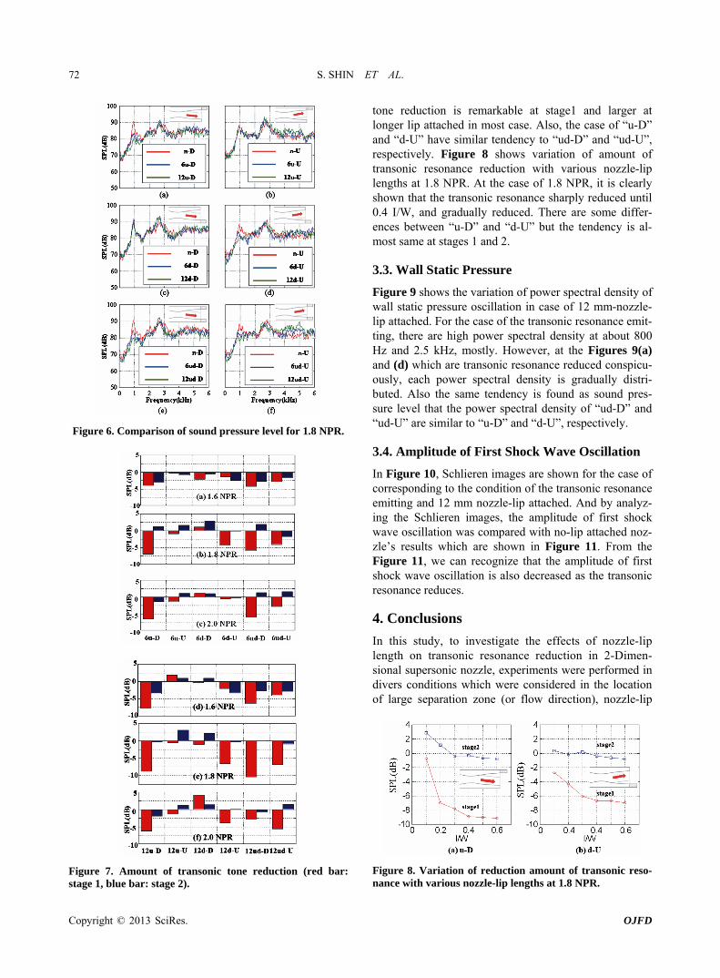
Figure 7 Amount of transonic tone reduction (red bar stage 1 blue bar stage 2)
tone reduction is remarkable at stage1 and larger at longer lip attached in most case Also the case of ldquou-Drdquo and ldquod-Urdquo have similar tendency to ldquoud-Drdquo and ldquoud-Urdquo respectively Figure 8 shows variation of amount of transonic resonance reduction with various nozzle-lip lengths at 18 NPR At the case of 18 NPR it is clearly shown that the transonic resonance sharply reduced until 04 IW and gradually reduced There are some differ- ences between ldquou-Drdquo and ldquod-Urdquo but the tendency is al- most same at stages 1 and 2
33 Wall Static Pressure
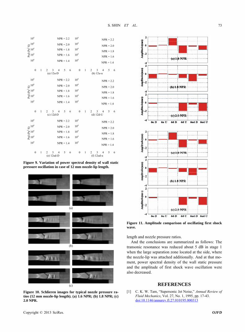
Figure 9 shows the variation of power spectral density of wall static pressure oscillation in case of 12 mm-nozzle- lip attached For the case of the transonic resonance emit- ting there are high power spectral density at about 800 Hz and 25 kHz mostly However at the Figures 9(a) and (d) which are transonic resonance reduced conspicu- ously each power spectral density is gradually distri- buted Also the same tendency is found as sound pres- sure level that the power spectral density of ldquoud-Drdquo and ldquoud-Urdquo are similar to ldquou-Drdquo and ldquod-Urdquo respectively
34 Amplitude of First Shock Wave Oscillation
In Figure 10 Schlieren images are shown for the case of corresponding to the condition of the transonic resonance emitting and 12 mm nozzle-lip attached And by analyz- ing the Schlieren images the amplitude of first shock wave oscillation was compared with no-lip attached noz- zlersquos results which are shown in Figure 11 From the Figure 11 we can recognize that the amplitude of first shock wave oscillation is also decreased as the transonic resonance reduces
4 Conclusions
In this study to investigate the effects of nozzle-lip length on transonic resonance reduction in 2-Dimen- sional supersonic nozzle experiments were performed in divers conditions which were considered in the location of large separation zone (or flow direction) nozzle-lip
Figure 8 Variation of reduction amount of transonic reso- nance with various nozzle-lip lengths at 18 NPR
Copyright copy 2013 SciRes OJFD
S SHIN ET AL 73
0 1 2 3 4 5 6
104
104
104
104
104 NPR = 22
NPR = 20
NPR = 18
NPR = 16
NPR = 14
Psd
(Pa2
S)
(a) 12u-D 0 1 2 3 4 5 6
104
104
104
104
104 NPR = 22
NPR = 20
NPR = 18
NPR = 16
NPR = 14
(b) 12u-u
0 1 2 3 4 5 6
104
104
104
104
104 NPR = 22
NPR = 20
NPR = 18
NPR = 16
NPR = 14
Psd
(Pa2
S)
(c) 12d-D 0 1 2 3 4 5 6
104
104
104
104
104 NPR = 22
NPR = 20
NPR = 18
NPR = 16
NPR = 14
(d) 12d-U
0 1 2 3 4 5 6
104
104
104
104
104 NPR = 22
NPR = 20
NPR = 18
NPR = 16
NPR = 14
Psd
(Pa2
S)
(e) 12ud-D 0 1 2 3 4 5 6
104
104
104
104
104 NPR = 22
NPR = 20
NPR = 18
NPR = 16
NPR = 14
(f) 12ud-u
Figure 9 Variation of power spectral density of wall static pressure oscillation in case of 12 mm nozzle-lip length
(a)
(b)
(c)
Figure 10 Schlieren images for typical nozzle pressure ra- tios (12 mm nozzle-lip length) (a) 16 NPR (b) 18 NPR (c) 20 NPR
Figure 11 Amplitude comparison of oscillating first shock wave length and nozzle pressure ratios
And the conclusions are summarized as follows The transonic resonance was reduced about 5 dB in stage 1 when the large separation zone located at the side where the nozzle-lip was attached additionally And at that mo- ment power spectral density of the wall static pressure and the amplitude of first shock wave oscillation were also decreased
REFERENCES [1] C K W Tam ldquoSupersonic Jet Noiserdquo Annual Review of
Fluid Mechanics Vol 27 No 1 1995 pp 17-43 doi101146annurevfl27010195000313
Copyright copy 2013 SciRes OJFD
S SHIN ET AL
Copyright copy 2013 SciRes OJFD
74
[2] K B M Q Zaman M D Dahl T J Bencic and CY Loh ldquoInvestigation of a Transonic Resonance with Con- vergent-Divergent Nozzlesrdquo Journal of Fluid Mechanics
Vol 463 No 1 2002 pp 313-343 doi101017S0022112002008819

S SHIN ET AL 70
height of 96 mm exit height of 172 mm (H) width of 30 mm (W) and the length of divergent section was 46 mm (L) as shown in Figure 2 The sidewalls of the su- personic nozzle have optical grasses to allow flow visu- alization by a schlieren optical system To measure the position of the shock wave in the nozzle-divergent sec- tion while the transonic resonance occurs visualization was performed by schlieren method with high-speed video camera [Photron FASTCAM SA5] The movie was recorded as the frame rate was 10000 fps with 5 μs- shutter speed And measurement time and pixel count are 16 s and 256 times 512 respectively Acoustic measure- ments were made by using a condenser microphone [Ono-Sokki MI-6420] that has a diameter of 14 inch And the microphone which shown in Figure 3 was lo- cated at angles (θ) of 60 degrees from the jet flow direc- tion and a radial distance of 516 mm from the exit of the nozzle (rH = 30) The acoustic signals were analyzed using the FFT analyzer [Ono-Sokki DS0221] The FFT analysis provided the noise spectra in the range from 0 to 40 kHz with a frequency bandwidth of 25 Hz And the pressure measurements were done by setting up the pressure ports at xL = 087 from the nozzle throat using
the semiconductor pressure sensor [TEAC XCS-190] The sampling frequencies of condenser microphone and semiconductor pressure sensor are the same with 50 kHz
22 Experimental Procedure
In this paper the nozzle pressure ratio (NPR) is defined as the ratio of the pressure inside the plenum chamber p0 to ambient back pressure pb According to the one-di- mensional analysis for the present nozzle the correct expansion state at the nozzle exit is obtained at NPR = 78 And experiment was carried out for different nozzle pressure ratios from 14 to 22 And nozzle-lip length was varied to study its effect on the transonic resonance by attaching cuboid tips on the nozzle exit The tip has 6mm height 30 mm width and 6 mm (I) or 12 mm (I) length Also the location of large separation zone (or flow direc- tion) was varied at each experimental case Table 1 shows detail of experimental conditions about all cases In Table 1 subscript ldquonrdquo ldquourdquo ldquodrdquo and ldquoudrdquo mean ldquono-liprdquo ldquoupper siderdquo ldquobottom siderdquo and ldquoboth siderdquo at- tached condition respectively And ldquoUrdquo and ldquoDrdquo mean flow direction or the opposite side of large separation zone location
Mirror
Light source
Pin hole
Knife edge
CameraSupersonic nozzle
Pressure transducer
Plenum chamber
Amplifier
AD converter
Personal computer
Signal controller
Pressure control valve
Reservior30MPa 5m
3
Compressor
325
160
5250
1000
4900
Absorption material
Supersonic jet
Air outlet
Figure 1 Experimental apparatus and measuring system
Figure 2 Supersonic nozzle geometry
Copyright copy 2013 SciRes OJFD
S SHIN ET AL 71
Microphone
Pressure Transducer jet
r = 516 (rH = 30)
flow
Laval Nozzle
72deg
L = 46
H = D = 96 172
Figure 3 Measurement point of sound pressure level
Table 1 Experimental sets
6 mm 12 mm 6 mm 12 mm
6n-D 12n-D 6u-U 12u-U
6u-D 12u-D 6u-U 12u-U
6d-D 12d-D 6d-U 12d-U
6ud-D 12ud-D 6ud-U 12ud-U
3 Results and Discussion
31 Sound Spectra and Tone Frequency
Figure 4 shows the sound pressure spectra in case of normal nozzle And the red and blue solid line mean downside and upside flow direction In Figure 4 there are some peak value of sound pressure level at about 800 Hz and 25 kHz which is known as transonic resonance of stage 1 (solid arrow) and stage 2 (open arrow) respec- tively According to Zaman et al standing one-quarter three-quarter waves exist between the shock wave and nozzle exit And the frequency of transonic resonance is proportional to NPR because the shock wave in the di- vergent section moves to the downstream as the NPR increases and the distance between the shock wave and nozzle exit shorten And each difference of sound pres- sure level between ldquon-Drdquo and ldquon-Urdquo is less than 2 dB In Figure 5 the frequency of the transonic resonance and calculated value by Zamanrsquos empirical formula are plot- ted with nozzle pressure ratio As shown in Figure 5 there are some gaps between broken line of Zamanrsquos for- mula and each transonic tone frequency However a similar tendency is seen that the transonic tone increases with increasing of NPR
32 Reduction of Transonic Resonance
It is shown comparisons of sound pressure level ac-
Figure 4 Variation of sound pressure level for n-D and n-U
Figure 5 Comparison of transonic tone frequency between experiment and Zamanrsquos empirical formula cording to nozzle-lip length and flow direction at 18 NPR in Figure 6 And it is clearly shown that the stage1 transonic resonance is reduced at the case of (a) (d) (e) and (f) In case of ldquod-Drdquo at Figures 6(b) and (c) how- ever there are little effects of nozzle-lip length Mean- while in Figures 6(e) and (f) the transonic resonance is reduced both cases and each sound pressure spectra are almost same with (a) and (d) respectively Therefore it can be considered that the effect of reduction is valid for stage 1 when the large separation zone locates at the side of nozzle-lip attached And effects of reduction are larger at 12 mm nozzle-lip length than 6 mm Each amount of transonic resonance reduction is plotted in bar chart in Figure 7 The same tendency like 18 NPR reviewed in Figure 6 is shown at every case That is the amount of
Copyright copy 2013 SciRes OJFD
S SHIN ET AL 72
Figure 6 Comparison of sound pressure level for 18 NPR
Figure 7 Amount of transonic tone reduction (red bar stage 1 blue bar stage 2)
tone reduction is remarkable at stage1 and larger at longer lip attached in most case Also the case of ldquou-Drdquo and ldquod-Urdquo have similar tendency to ldquoud-Drdquo and ldquoud-Urdquo respectively Figure 8 shows variation of amount of transonic resonance reduction with various nozzle-lip lengths at 18 NPR At the case of 18 NPR it is clearly shown that the transonic resonance sharply reduced until 04 IW and gradually reduced There are some differ- ences between ldquou-Drdquo and ldquod-Urdquo but the tendency is al- most same at stages 1 and 2
33 Wall Static Pressure
Figure 9 shows the variation of power spectral density of wall static pressure oscillation in case of 12 mm-nozzle- lip attached For the case of the transonic resonance emit- ting there are high power spectral density at about 800 Hz and 25 kHz mostly However at the Figures 9(a) and (d) which are transonic resonance reduced conspicu- ously each power spectral density is gradually distri- buted Also the same tendency is found as sound pres- sure level that the power spectral density of ldquoud-Drdquo and ldquoud-Urdquo are similar to ldquou-Drdquo and ldquod-Urdquo respectively
34 Amplitude of First Shock Wave Oscillation
In Figure 10 Schlieren images are shown for the case of corresponding to the condition of the transonic resonance emitting and 12 mm nozzle-lip attached And by analyz- ing the Schlieren images the amplitude of first shock wave oscillation was compared with no-lip attached noz- zlersquos results which are shown in Figure 11 From the Figure 11 we can recognize that the amplitude of first shock wave oscillation is also decreased as the transonic resonance reduces
4 Conclusions
In this study to investigate the effects of nozzle-lip length on transonic resonance reduction in 2-Dimen- sional supersonic nozzle experiments were performed in divers conditions which were considered in the location of large separation zone (or flow direction) nozzle-lip
Figure 8 Variation of reduction amount of transonic reso- nance with various nozzle-lip lengths at 18 NPR
Copyright copy 2013 SciRes OJFD
S SHIN ET AL 73
0 1 2 3 4 5 6
104
104
104
104
104 NPR = 22
NPR = 20
NPR = 18
NPR = 16
NPR = 14
Psd
(Pa2
S)
(a) 12u-D 0 1 2 3 4 5 6
104
104
104
104
104 NPR = 22
NPR = 20
NPR = 18
NPR = 16
NPR = 14
(b) 12u-u
0 1 2 3 4 5 6
104
104
104
104
104 NPR = 22
NPR = 20
NPR = 18
NPR = 16
NPR = 14
Psd
(Pa2
S)
(c) 12d-D 0 1 2 3 4 5 6
104
104
104
104
104 NPR = 22
NPR = 20
NPR = 18
NPR = 16
NPR = 14
(d) 12d-U
0 1 2 3 4 5 6
104
104
104
104
104 NPR = 22
NPR = 20
NPR = 18
NPR = 16
NPR = 14
Psd
(Pa2
S)
(e) 12ud-D 0 1 2 3 4 5 6
104
104
104
104
104 NPR = 22
NPR = 20
NPR = 18
NPR = 16
NPR = 14
(f) 12ud-u
Figure 9 Variation of power spectral density of wall static pressure oscillation in case of 12 mm nozzle-lip length
(a)
(b)
(c)
Figure 10 Schlieren images for typical nozzle pressure ra- tios (12 mm nozzle-lip length) (a) 16 NPR (b) 18 NPR (c) 20 NPR
Figure 11 Amplitude comparison of oscillating first shock wave length and nozzle pressure ratios
And the conclusions are summarized as follows The transonic resonance was reduced about 5 dB in stage 1 when the large separation zone located at the side where the nozzle-lip was attached additionally And at that mo- ment power spectral density of the wall static pressure and the amplitude of first shock wave oscillation were also decreased
REFERENCES [1] C K W Tam ldquoSupersonic Jet Noiserdquo Annual Review of
Fluid Mechanics Vol 27 No 1 1995 pp 17-43 doi101146annurevfl27010195000313
Copyright copy 2013 SciRes OJFD
S SHIN ET AL
Copyright copy 2013 SciRes OJFD
74
[2] K B M Q Zaman M D Dahl T J Bencic and CY Loh ldquoInvestigation of a Transonic Resonance with Con- vergent-Divergent Nozzlesrdquo Journal of Fluid Mechanics
Vol 463 No 1 2002 pp 313-343 doi101017S0022112002008819
S SHIN ET AL
Copyright copy 2013 SciRes OJFD
74
[2] K B M Q Zaman M D Dahl T J Bencic and CY Loh ldquoInvestigation of a Transonic Resonance with Con- vergent-Divergent Nozzlesrdquo Journal of Fluid Mechanics
Vol 463 No 1 2002 pp 313-343 doi101017S0022112002008819

![Transonic Potential Flows in A …arXiv:0802.2324v1 [math.AP] 16 Feb 2008 Transonic Potential Flows in A Convergent–Divergent Approximate Nozzle Hairong Yuana,1 Yue Heb,2 a Department](https://img.pdfslide.us/doc/110x75/5e431dbd8a20586bc3362718/transonic-potential-flows-in-a-arxiv08022324v1-mathap-16-feb-2008-transonic.jpg)