Embed Size (px)
Citation preview

SSC-174
Investigation of Residual Stresses
h Steel Weldments
by
KOICHI MASUBUCHI and D. C. MARTIN
SHIP STRUCTURE COMMITTEE
SHIP STRUCTURE COMMITTEE
MEMB8R AGENCIES:
B“n EA” OF SHIPS, D<PT, 0< N.””
MI I.,TARV SEA TRANSPORTA7,0N S,.”,.,, D,,,, OF N.”,
UNITED S7.7,S co,,, GUARD, 7.,.s”. ” DEPT.
MA”, T,M6 ADM, N, STRA7,0N, DEPT. OF Cc.. ”...,
AM ER, C&N BUREAU OF S“,,,,..
September 1966
ADDRESS CORR.ZWONDENCE TO:
—...s- . s-mm., COuu,rr,.. S CO- Guam. HSAOO”A.TEIM
6.s. .370. Q c 20226
Dear Sir:
Novel methods of measuring residual stresses in mi Id
steel are constantly being proposed to obviate their effects
in the brittle fracture problem. The Ship Structure Com-
mittee undertakes , whenever poss i ble, the most favorable
approaches. One such proposal suggested the use of a hy-
drogen- induced-cracking technique. The attached report rep-
resents the results and description of such a study under-
taken at Battelle Memorial Institute.
In sponsoring thei r research projec~ the Ship Struc-
ture Commi ttee received guidance and review from the Nat ion-
al Academy of Sciences through its Ship Hul 1 Research Com-mittee, and a project advisory conmittee (S R-167, “Residual
Stresses in Steel Weldments”) . The Academy undertakes this
research advisory service to the Ship Structure Comnitteethrough a contract arrangement.
Consnents on this report would be welccme and should
be adressed to the Secretary, Ship Structure Committee.
Sincerely yours,
@
& (2&_.>John B. OrenRear Admiral , U. S. Coast Guard
Chairman, Ship Structure Committee
I
1
— .
SSC-174
Final Report
on
Project SR-167
“Investigate on of Residual Stressesin Steel Weldments”
to the
Ship Structure Committee
INVESTIGATION OF RESIDUAL STRESSES
IN STEEL WELDMENTS
by
Koichi Masubuchi and D. C. Martin
Battelle Memorial InstituteColumbus, Ohio
under
Department of the NavyBureau of Ships Contract NObs 92521
Washington, D. C.National Academy of Sciences - National Research Counci 1
September 1966
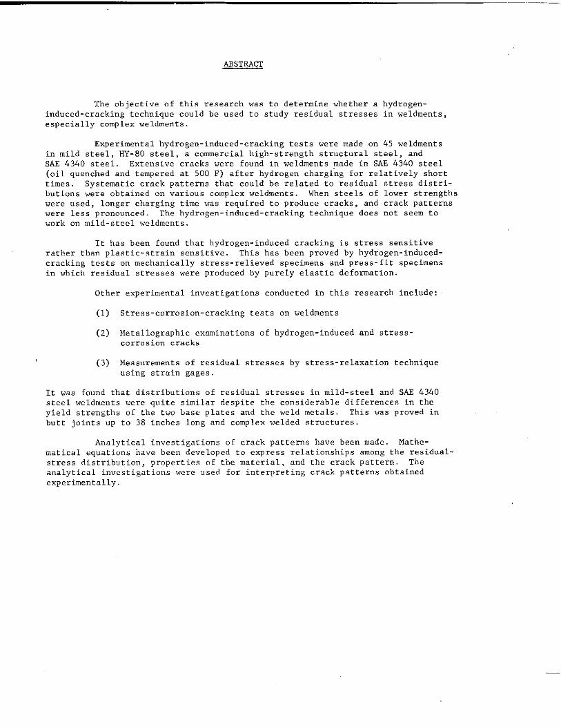
The objective ofinduced-cracking technique
ABSTSACT
this research was to determine whether acould be used to study residual stresses
especially complex weldments.
Experimental hydrogen-induced-cracking tests were made on
hydrogen-in weldments,
45 weldmentsin mild steel, HY-80 steel, a commercial high-strength structural steel, andSAE 4340 steel. Extensive cracks were found in weldments made in SAE 4340 steel(oil quenched and tempered at 500 F) after hydrogen chargi’ng for relatively shorttimes. Systematic crack patterns that could be related to residual stress distri-butions were obtained on various complex weldments. When steels of lower strengthswere used, longer charging time was required to produce cracks, and crack patternswere less pronounced. The hydrogen-induced-cracking technique does not seem towork on mild-steel weldments.
It has been found that hydrogen-induced cracking is stress sensitiverather than plastic-strain sensitive. This has been proved by hydrogen-induced-cracking tests on mechanically stress-relieved specimens and press-fit specimensin which residual stresses were produced by purely elastic deformation.
Other experimental investigations conducted in this research include:
(1) Stress-corrosion-cracking tests on weldments
(2) Metallographic examinations of hydrogen-induced and stress-corrosion cracks
(3) Measurements of residual stresses by stress-relaxation techniqueusing strain gages.
It was found that distributions of residual stresses in mild-steel and SAE 4340steel weldments were quite similar despite the considerable differences in theyield strengths of the two base plates and the weld metals. This was proved in
butt joints up to 38 inches long and complex welded structures.
Analytical investigations of crack patterns have been made. Mathe-
matical equations have been developed to express relationships among the residual-stress distribution, properties of tbe material, and the crack pattern. The
analytical investigations were used for interpreting crack patterns obtainedexperimentally.
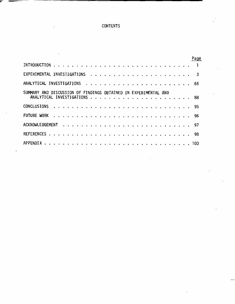
CONTENTS
INTRODUCTION . . . . . . . . . . . . . . . . .
EXPERIMENTAL INVESTIGATIONS . . . . . . . . .
ANALYTICAL INVESTIGATIONS . . . . . . . . .
SUMMARY ANO DISCUSSION OF FINOINGS OBTAINEOANALYTICAL INVESTIGATIONS . . . . . . . .
CONCLUSIONS . . . . . . . . . . . . . . . .
FUTURE WORK . . . . . . . . . . . . . . . .
ACKNOWLEOGEMENT . . . . . . . . . . . . . .
N
REFERENCES . . . . . . . . . . . . . . . . . .
APPENDIX . . . . . . . . . . . . . . . . . . .
. . . . . . . . . . . . .
. . . . . . . . . . . . .
. . . . . . . . . . . . .
EXPERIMENTAL AND
. . . . . . . . . . . . .
. . . . . . . . . . . . .
. . . . . . . . . . . . .
. . . . . . . . . . . . .
. . . . . . . . . . . . .
. . . . . . . . . . . . .
1
3
66
88
95
96
97
98
100
SHIP STRUCTURECOM4TTTEE
The SHIP STROC17JRECOMMTTTEE is constitutedto prosecutea w~eareh program to improve
the hull structuresof shipsby an extensionof knoiledgepertaining to design,materialsand
methods of fabrication.
Rear Admiral John B. Oren, USCG -Chief, Office of EngineeringU. S. Coast Guard Headquarters
CaptainW. M. Nicholson,USN Mr. E.AssistantChief of Bureau of Desisn Chief.
Chairman
M. NacCutcheonOffice of Researchand
Shipbuildingand Tleet tiinten;nce DevelopmetItBureau of Ships MaritimeAdministration
CaptainP. E. Shetenhelrn,USN Hr. U. B. Bannerman,Jr.Maintenanceand Repair Officer Vice President- TechnicalMilitary Sea TransportationService AmericanBureau of Shipping
SHIP STROCTURESUBCOMMITTEE
The Ship StructureS& committeeacts for the Ship StructureConmritteeon technicalmatters
by providing technicalcoordinationfor the determinationof goals and ab.jectiue?sof the pro -
WOJTI,and by evaluatingand interpretingthe result~ in terms of ship structuraldesign, con-
strwationawd operation.
BURSAU OF SHIPS OFFICE OF NAVAL RESEARCH
Capt.linS. R. Heller, USN - Chairman fir.J. FL crowley – HemberMI. John Vast. - ContractAdministrator Dr. G. R. Irwin - AlternateMr. George Scmkin - Member Dr. Wm. G. Rauch - AlternateMr. ‘1.J. Griffin - AlternateMr. Ives Fioriti- Alternate MILITARY SEA TSANSPORTATIONSERVICE
MARITIMEADMINISTRATIONLCDR C. E. Arnold, USN – Member
MI. R. R. Askren - MemberMr. R. W. Black - MemberMr. An.toleMaillar - Alter”ate DAVID TAYLOR MODEL BASIN
AXBRICAXBUREAU OF SHIPPINGMr. A. B. Stavovy - Alternate
Mr. G. F. Casey - Member U. S. cOAST GUABJJMr. F. J. Crum – Member
LCDR R. Nielsen, Jr., USCG - MemberMr. J. B. Robertson,Jr. - MemberLCDR J. F. Lobkovich,USCG - AlternateCDR James L. Howard,USCG - Altenw.tc
LIA1sON ~pRRsENTAT1tIEs
NATIONALACADEMY OF SCIENCES- BRITIsHNAVY STAFFNATIoNALRESEASGRCOUNCIL
Mr. A. C. LawMr. A. R. Lytle - Director, Ship Hull Cmstructim Commander T. R. Rumms, RCNC
ResearchCommitteeMr. R. W. Rurnke- ExecutiveSecretary WELDING RRSEARCH COUNCIL
AMERICAN IRON AND STEEL INSTITUTE Mr. K.K, Koopman, DirectorMr. CharlesLarson – ExecutiveSecretary
fir.J. R. LeCron
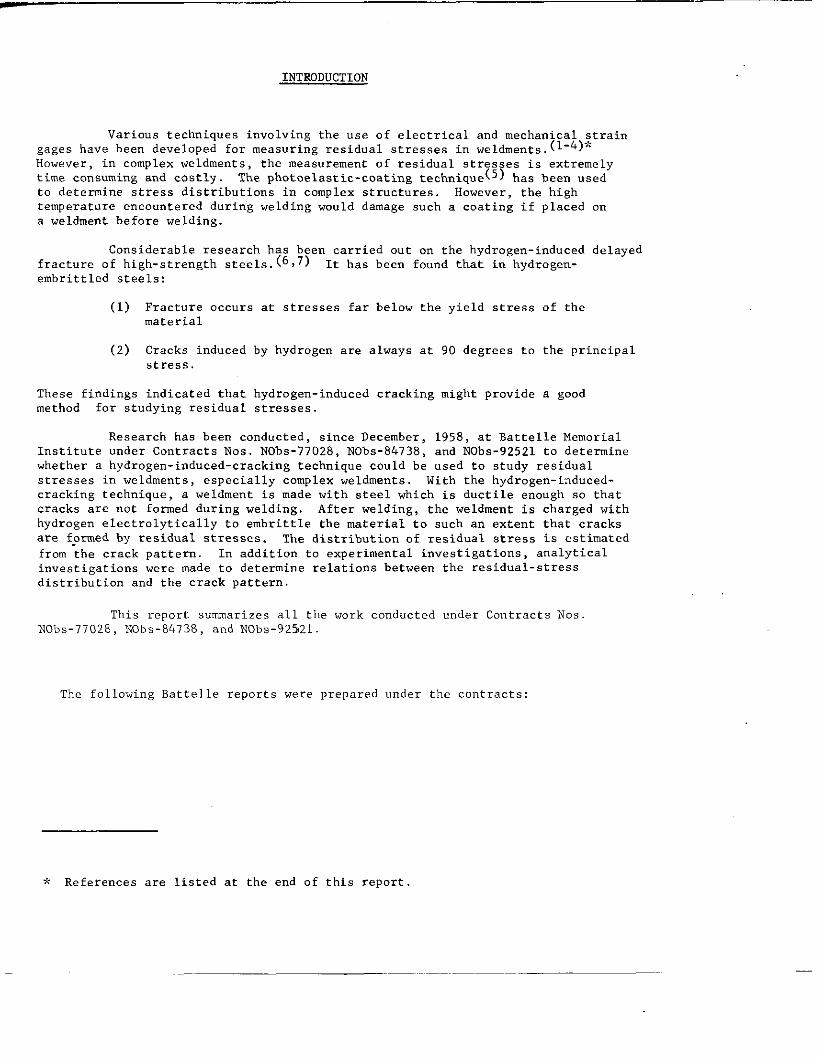
INTRODUCTION
Various techniques involving the use of electrical and mechanical straingages have been developed for measuring residual stresses in weldments. (1.4),(
However, in complex weldments, the measurement of residual stresses is extremelytime consuming and costly The photoelast ic-coating technique(s) has been usedto determine stress distributions in complex structures. However, tbe hightemperature encountered during wslding would damage such a coating if placed ona veldment before welding.
Considerable research has been carried out on the hydrogen-induced delayedfracture of high-strength steels. (6,7) It has been found that in hydrogen-
embrittled steels:
(1) Fracture occurs at stresses far below the yield stress of thematerial
(2) Cracks induced by hydrogen are always at 90 degrees to tbe principalstress.
These findings indicated that hydrogen-induced cracking might provide a goodmethod for studying residual stresses
Research has been conducted, since December, 1958, at Battelle MemorialInstitute under Contracts Nos. NObs-77028, NObs-84738, and NObs-92521 to determinewhether a hydrogen-induced-cracking tecb”ique could be used to study residualstresses in weldments, especially complex weldments, With the hydrogen-induced-cracking technique, a weldment is made with steel which is ductile enough so thatcracks are not formed during welding. After welding, the weldment is charged withhydrogen electrolytically to embrittle tbe material to such an extent that cracksare formed by residual stresses. The distribution of residual stress is estimatedfrom tbe crack pattern. In addition to experimental investigations, analyticalinvestigations were made to determine relations between the residual-stressdistribution and the crack pattern.
This report summarizes all the work conducted under Contracts NosNObs-77028, NObs-84738, and NObs-92521.
The following Battelle reports were prepared under the contracts:
* References are listed at the end of this report.
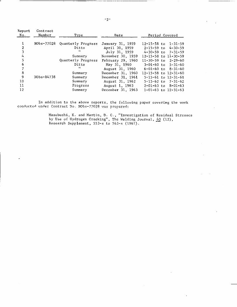
Report~
123456789101112
ContractNumber Type
NObs-77028 Quarterly ProgressDitto
!,
SummaryQuarterly Progress
Ditto,!
SummaryNObs-84738 Summary
SummaryProgressSummary
-2-
Date
January 31, 1959April 30, 1959July 31, 1959
November 30, 1959February 29, 1960May 31, 1960August 31, 1960
December 31, 1960December 31, 1961August 31, 1962August 1, 1963
December 31, 1963
Period Co”ered
12-15-58 to 1-31-592-15-59 to 4-30-594-30-59 to 7-31-5912-15-58 to 11-30-5911-30-59 to 2-29-603-01-60 to 5-31-606-01-60 to 8-31-6012-15-58 to 12-31-605-15-61 to 12-31-615-15-62 to 7-31-622-01-63 to 8-01-631-01-63 to 12-31-63
In addition to tbe above reports, tbe following paper covering tbe workconducted under Contract No. NObs-77028 was prepared:
Masubucbi, K. and Martin, D. c. , “Investigation of Residual Stressesby Use of Hydrogen Cracking”, Tbe Welding Journal, LO (12),
Research Supplement, 553-s to 563-s (1961).
—- .——
-3-
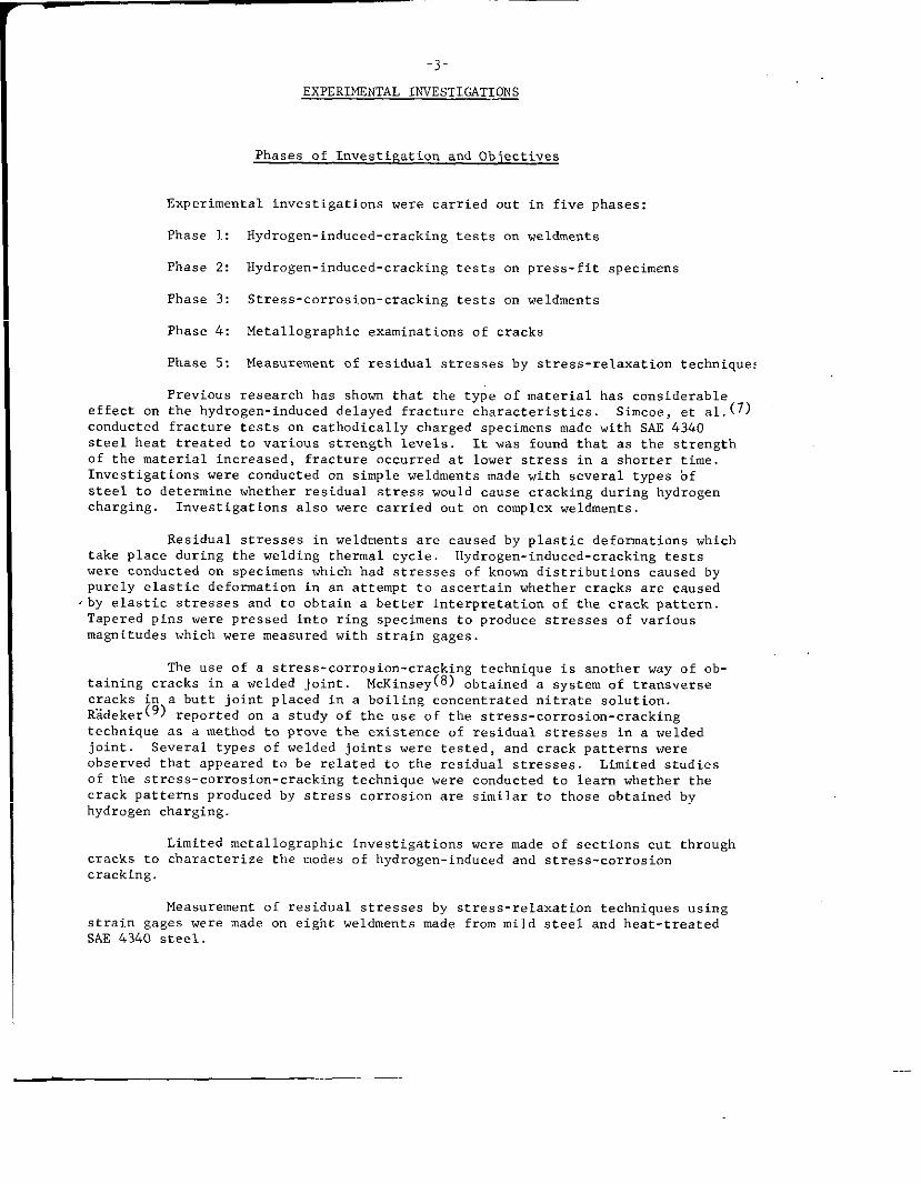
EXPERIMENTAL INVESTIGATIONS
Phases of Investigation and Objectives
Experimental investigations were carried out in five phases:
Phase 1: Hydrogen-induced-cracking tests on weldrnents
Phase 2: Hydrogen-induced-cracking tests on press-fit specimens
Phase 3: Stress-corrosion-cracking tests on weldments
Phase 4: Metal lographic examinations of cracks
Phase 5t Measurement of residual stresses by stress-relaxation techniques
Previous research has shown that the type of material has considerableeffect on the hydrogen-induced delayed fracture characteristics Simcoe, et al.(7)conducted fracture tests on catholically charged specimens made with SAE 4340steel heat treated to various strength levels. It was found that as the strengthof the material increased, fracture occurred at lower stress in a shoi-tertime.Investigations were conducted on simple weldments made with several types ofsteel to determine whether residual stress vm”ld cause cracking during hydrogencharging. Investigations also were carried out on complex weldnwnts
Residual stresses in weldments are caused by plastic deformations whichtake place during the welding thermal cycle, Hydrogen-induced-cracking testswere conducted on specimens which had stresses of kmmm distributions caused bypurely elastic deformation in an attempt to ascerta.i”whether cracks are caused
.by elastic stresses a“d to obtain a better interpretation of the crack pattern.Tapered pins were pressed into ring specimens to produce stresses of “ariousmagnitudes which were measured with strain gages
The use of a stress-corrosion-cracking technique is another way of ob-taining cracks in a welded joint McKinley obtained a system of transversecracks in a butt joint placed in a boiling ccmcentrated nitrate solution.R3.deker(9) reported o“ a study of the use of the stress-corrosion-crackingtechnique as a method to prove the existence of residual stresses in a weldedjoint. Several types of welded joints were tested, and crack patterns wereobserved that appeared to be related to the residual stresses. Limited studiesof the stress-corrosion-cracking technique “ere conducted to learn whether thecrack patterns produced by stress corrosion aI-esimilar to those obtained byhydrogen charging.
Limited metal lographic investigations were made of sections cut throughcracks to characterize the modes of hydrogen-induced and stress-corrosioncracking.
Measurement of residual stresses by stress-relaxation techniques usingstrain gages were made on eight weldments made from mild steel and heat-treatedSAE 434o steel.
—
-4-
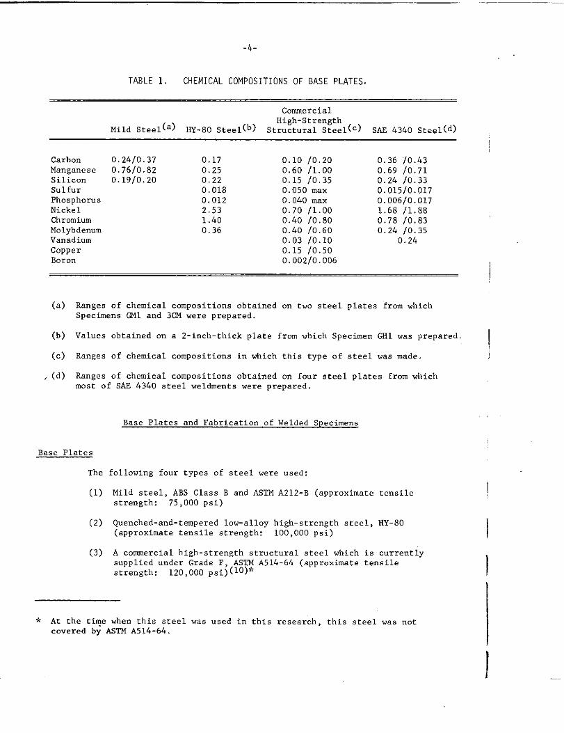
TABLE 1. CHEMICAL COMPOSITIONS OF BASE PLATES
CommercialHigh-Strength
Mild Steel(a) HY-80 steel(b) st=~Ct”ral Steel(c) SM 4340 steel(d)
CarbonManganeseSiliconSulfurPhosphorusNickelChromiumMolybdenumVanadiumCopperBoron
0.24/0.37 0.170.76/0.82 0.250.19/0.20 0.22
0.0180.0122.531.400.36
0.10 /0.200.60 /1.000.15 /0.350.050 maxO.040 max0.70 /1.000.40 /0.800.40 /0.600.03 /0.100.15 /0.500.002/0.006
0.36 10.430.69 /0.710.24 /0.330.015/0.0170.006/0.0171.68 /1.880.78 /0.830.24 /0.35
0.24
(a)
(b)
(c)
, (d)
Ranges of chemical compositions obtained on two steel plates from whichSpecimens Q41 and 301 were prepared.
Values obtained on a 2-inch-thick plate from which Specimen ml was prepared.
Ranges of chemical compositions in which this type of steel was made
Ranges of chemical compositions obtained cm four steel plates from “hichmost of SAE 4340 steel weldme”ts were prepared.
Base Plates
The
(1)
(2)
(3)
Base Plates and Fabrication of Welded Specimens
following four types of steel were used:
Mild steel, ABS Class B and ASTM A212-B (approximate tensilestrength: 75,000 psi)
Quenched-and-tempered low-alloy high-strength steel, HY-80(approximate tensile strength: 100,000 psi)
A cormnercialhigh-strength structural steel which is currentlysupplied under Grade F, AS211A514-64 (approximate tensilestrength: 120,000 psi) (lO)+’
—
* At the ti?e when this steelcovered by tiglllA514-64.
was used in this research, this steel was not
I
I
I
I
!
I
-5-
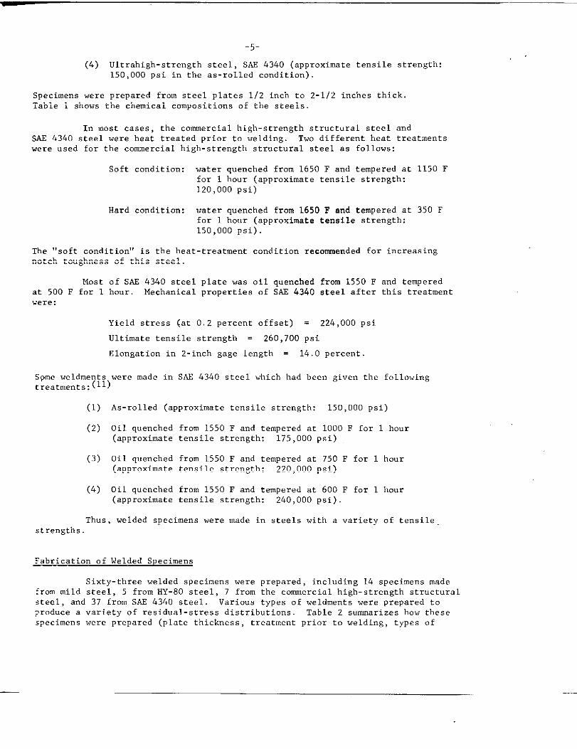
(4) Ultrahigh-strength steel, SAl!4340 (approximate tensile strength:150,000 psi in the as-rolled condition)
Specimens were prepared from steel plates 1/2 inch to 2-1/2 inches thick.Table I shows the chemical compositions of the steels.
In most cases, the commercial high-strength structural steel andSAE 4340 steel were heat treated prior to welding. Two different heat treatmentswere used for the commercial high-strength structural steel as follows:
Soft condition: water quenched from 1650 F and tempered at 1150 Ffor 1 hour (approximate tensile strength:120,000 psi)
Hard condition: water quenched from 1650 F and tempered at 350 Efor 1 hour (approximate tensile strength:150,000 psi).
The “soft condition” is the heat-treatment condition recommended for increasingnotch toughness of this steel.
Mostat 500 F for 1were:
of SAE 4340 steel plate was oil quenched from 1550 F and temperedhour Mechanical properties of SAE 4340 steel after this treatment
Yield stress (at 0.2 percent offset) = 224,000 psi
Ultimate tensile strength = 260,700 psi
Elongat ion in 2-inch gage length = 14.0 percent.
Spreeweldments were made in SAE 4340 steel which had bee” given the followingtreatments:
(1) As-rolled (approximate tensile strength: 150,000 psi)
(2) Oil quenched from 1550 F and tempered at 1000 F for 1 hour(approximate tensile strength: 175,000 psi)
(3) Oil quenched from 1550 F and tempered at 750 F for 1 hour(approximate tensile strength: 220,000 psi)
(4) Oil quenched from 1550 F and tempered at 600 F for 1 hour(approximate tensile strength: 240,000 psi)
‘lh”s,welded specimens were made in steels with a variety of tensile
strengths.
Fabrication of Welded Specimens
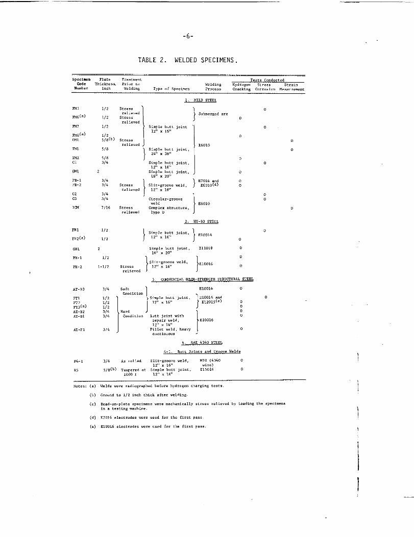
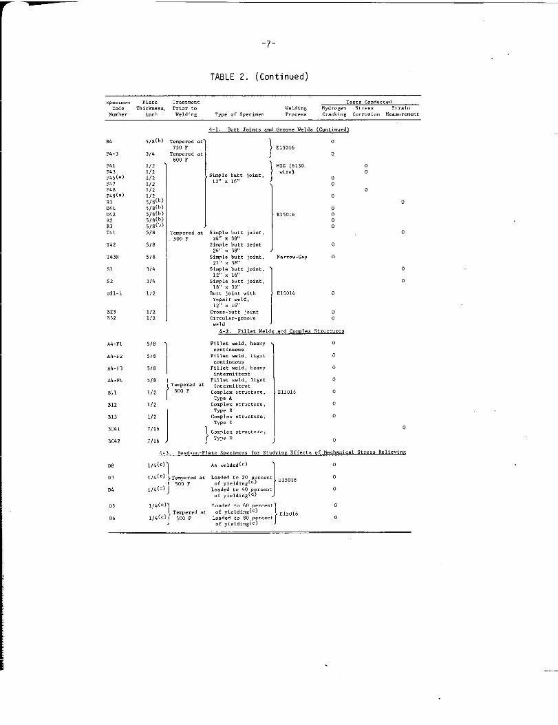
Sixty-three welded specimens were prepared, including 14 specimens madefrom mild steel, 5 from HY-80 steel, 7 from the commercial high-strength structuralsteel, and 37 from SAE 4340 steel. Various types of weldments were prepared to?roduce a variety of residual-stress distributions. Table 2 summarizes how thesespecimens were prepared (plate thickness, treatment prior to welding, types of
—
-6-
TABLE 2. WELDED SPECIMENS .
SP&” Plate Tr.atmw.t ,.,,8 . . . . . . . . .Thick.,,. P,,., t.
. ...,, ,.d,,.,.’., “,,..,.” S,,,,. ,,,.,.
we,di”, ,,,, ., s,,.,”’,. ,,.=,,s ,,..! 4., . . . . . . . . . .,.8..,.,”,
m,
~6(=)
EM,
~,(.)
0.,
‘ml
ml,c1
‘x,
,,-,,,.2
,2,3
,m
m,
m,(a)
,“1
ml- 1
,“- 2
AT-n]
n L,,2,,3(.)AT-n,.,-,,
,,-,1
,4.,
R,
1/,
1/>
1/,
;;:(b)
5/8
5/83/6
2
3/43/,
3/43/,
,,,”,1. butt j.,., ,,&,, , ~8,,
S’.,,. butt j.,.,,12 x ,6,,
S,,”,,. butt j.,”,,,6,, , m
,,,.-,,..,, “aid,,2,, , ,6,,
,,,..l .,-,,.....,,,
cm”,,,, structure
?,,. D
}
,Ub,”er,d .,.0
0
0
00
,60100
00
0
,70,6 .“,B60,0 (d)
,60,0
2. m-w STEEL
1/2
1/2} sti,~:t Joint } .10,,6 , 0
2 s,.,1. butt 3.{”,, E11018 o,6,, , ,., !
1/2
1 1
0
slit-*rows Wld, ,,00,6,-1/2 ,tre,s 12,, x 16,, 0
re, i?..d
,. ,0U5BCL4L .7.G- WW.N.T” BTR”CT”F.AL STEEL
3/4 soft ) ,,0016 0
1/21/21/1,/&3/4
CO.dit i.”
1)H::dit”!]simple butt joi.t, B~of5~f12<, x ,6,,
Butt joint .ich,.,s’, WZld, E1OO16,,,, , ,6,,
,,11., weld, h..”,......”..s
o
“
(b)
(c)
(d)
(.)
I
-7-
TABLE 2. (Continued)
M
w.,
,4,,,3W,(=),47,48,49(. )
:4 L0,2.2
::,
,42
,43,
s,
s,
B,, -,
.4-,,
.,-F,
,,-,3
AL. ,4
m,
,,,
,,3
3,,,
3,6,
m
.3
.4
,5
D,
,(O
3/,
,/21/21/21/21/21/,5/8(,5/8(,5/a(b5/8(,,/8(,5/8
5/8
>/8
,/,
3/4
,/2
,/2,/,
5/8
5/8
5(8
5/8
1/2
1/2
,/,
7/16
7/16
,,”,,,., .,)50 ,
}
,,>0,6,C”,erd atm, ,
, s,.,,.butt joint,,2,, ~ ,6,,
m“,.,., a.5’30 ,
,,.,1, ,.,. j.,., ,,,,, , ~8,,
,,,”,,. !,.,, j.,..,6,, ~ ~8,,
S,,”,,. ,.,, j.,”,,,,!, , ,,, !
S,,”,,, ,.,1 j.,”,,,2,, , ,,,,
s,.,], b.,, jot”,,,8,, , ,,, ,
,.,, ,.’”, .,,),repair W.,,12,, x ,6,,
cr.s, -b.tt j.,.,,,,,.,., -,....,..,,
,,5016
00
00
00
00
,,, ”,6
,’,1., weld, h,.,,. ...,..0”,
,,,,., we,.,Itsht
0
0
0
0
0
‘1
———
-8-
SPe CiIIIen, and welding process) and how theY were used ,9< Fo=tY-five ~pecimen~were used for the hydrogen-induced-cracking tests, 10 for the stress-corrosion-cracking tests, and 8 for the measurement of residual stresses by stress-relaxationtechniques.
Types of Welded Specimens. Eight types of welded specimens wereprepared:
(1) Simple butt joints, as shown in Figure 1
(2) Butt joints with repair welds
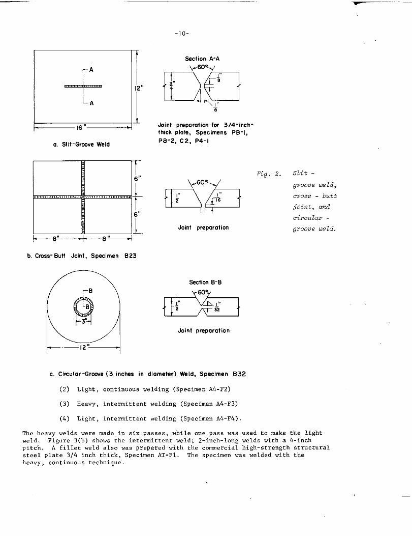
(3) Slit-groove welds, as shown in Figure 2(a)
(4) Cross butt joint, as shown in Figure 2(b)
(5) CircUlai_-groove welds, as shown in Fisure 2(C)
(6) Fillet welds, as shown in Figure 3
(7) Complex welded structures, as shown in Figure 4
(8) Bead-on-plate specimens.
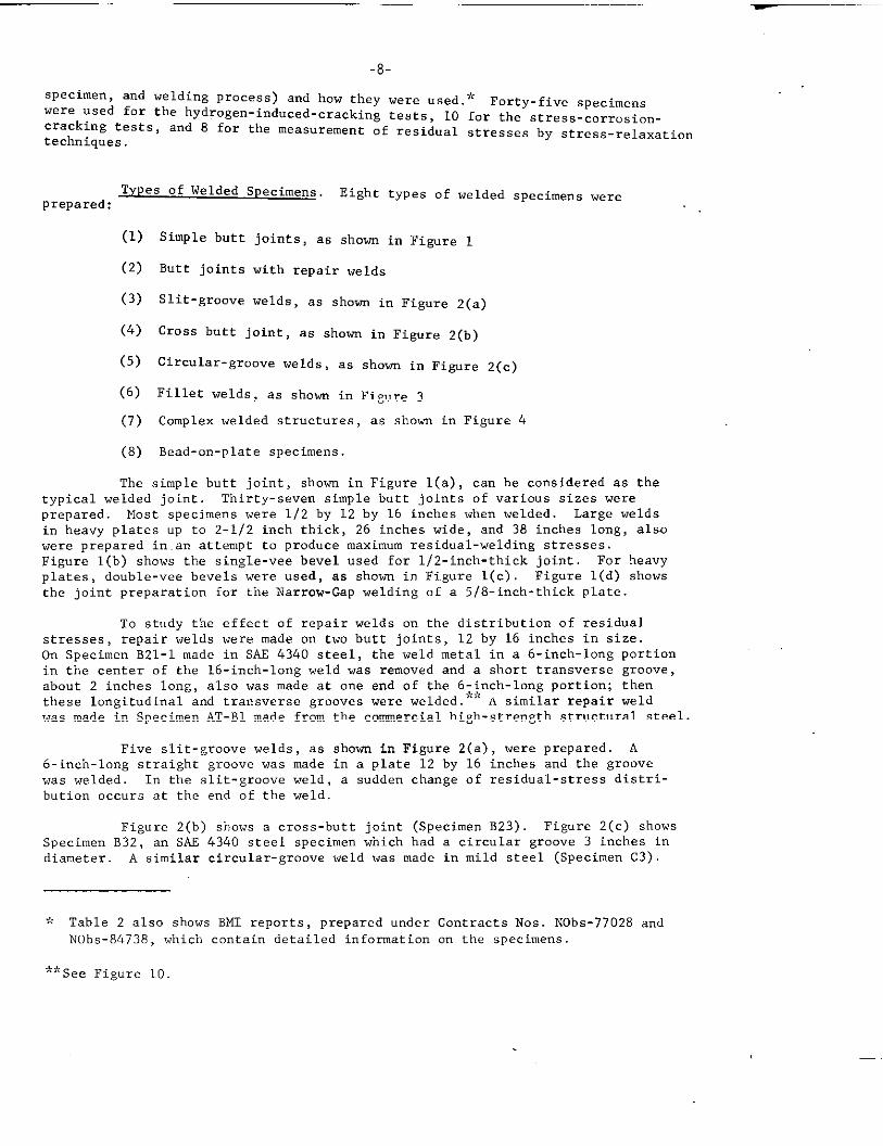
The simple butt joint, shown in Figure l(a), can be considered as the
typical welded joint. Thirty-seven simple butt joints of various sizes were
prepared. Most specimens were 1/2 by 12 by 16 inches when welded. Large weldsin heavy plates up to 2-1/2 inch thick, 26 inches wide, and 38 inches long, alsowere prepared in.an attempt to produce maximum residual-welding stresses.Figure l(b) shows the single-vee bevel used for l/2-inch-thick joint. For heavyplates, double-vee bevels were used, as shown in Figure l(c) Figure l(d) shows
the joint preparation for the Narrow-Gap welding of a 5/8-inch-thick plate.
To study the effect of repair welds on the distribution of residualstresses , repair welds were made on two butt joints, 12 by 16 inches in size.On Specimen B21-1 made in SAF 4340 steel, the weld metal in a 6-inch-long portionin the center of the 16-inch-long weld was removed and a short transverse groove,about 2 inches long, also was made at one end of the 6-inch-long portion; thenthese longitudinal and transverse grooves were welded.*<:A similar repair weldwas made in Specimen AT-B1 made from the commercial high-strength structural steel.
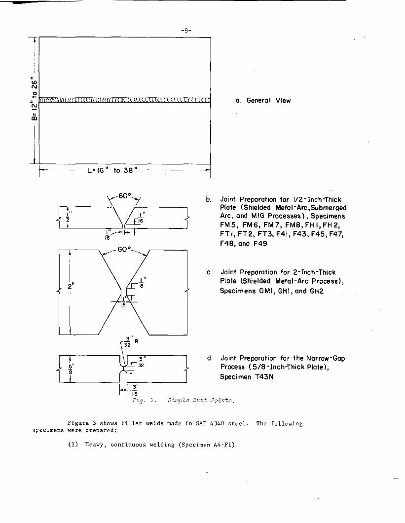
Five slit-groove welds, as shown in Figure 2(a) , were prepared. A6-inch-long straight groove was made in a plate 12 by 16 inches and the groovewas welded. In the slit-groove weld, a sudden change of residual-stress distri-bution occurs at the end of the weld.
Figure 2(b) shows a cross-butt joint (Specimen B23) Figure 2(c) showsSpecimen B32, an SAE 4340 steel specimen which had a circular groove 3 inches indiameter. A similar circular-groove weld was made in mild steel (Specimen C3)
$: Table 2 also shows BMI reports, prepared under Contracts Nos. NObs-77028 and
NObs-84738, which contain detailed information on the specimens.
**See Figure 10.
a. Genera I View
b. Jaint Preparation far 1/2- Inch-Thick
Plate (ShieldedMetal-Arc,SubmergedArc,and M IG Processes), SpecimensFM5, FM6, FM7, FM8, FHI, FH2,FT 1,FT2, FT3, F41, F43, F45, F47,F48, ond F49
c, Joint Preparation far 2-Inch-Thick
Plate (Shielded Metal-Arc Process),
Specimens GMI, GHI, and GH2
d. JaintPrepuratianfar the Narraw-GapPracess (5/8-Inch-Thick Plate),
Specimen T43N
H%Fig. 1. Simpte Butt Joints.
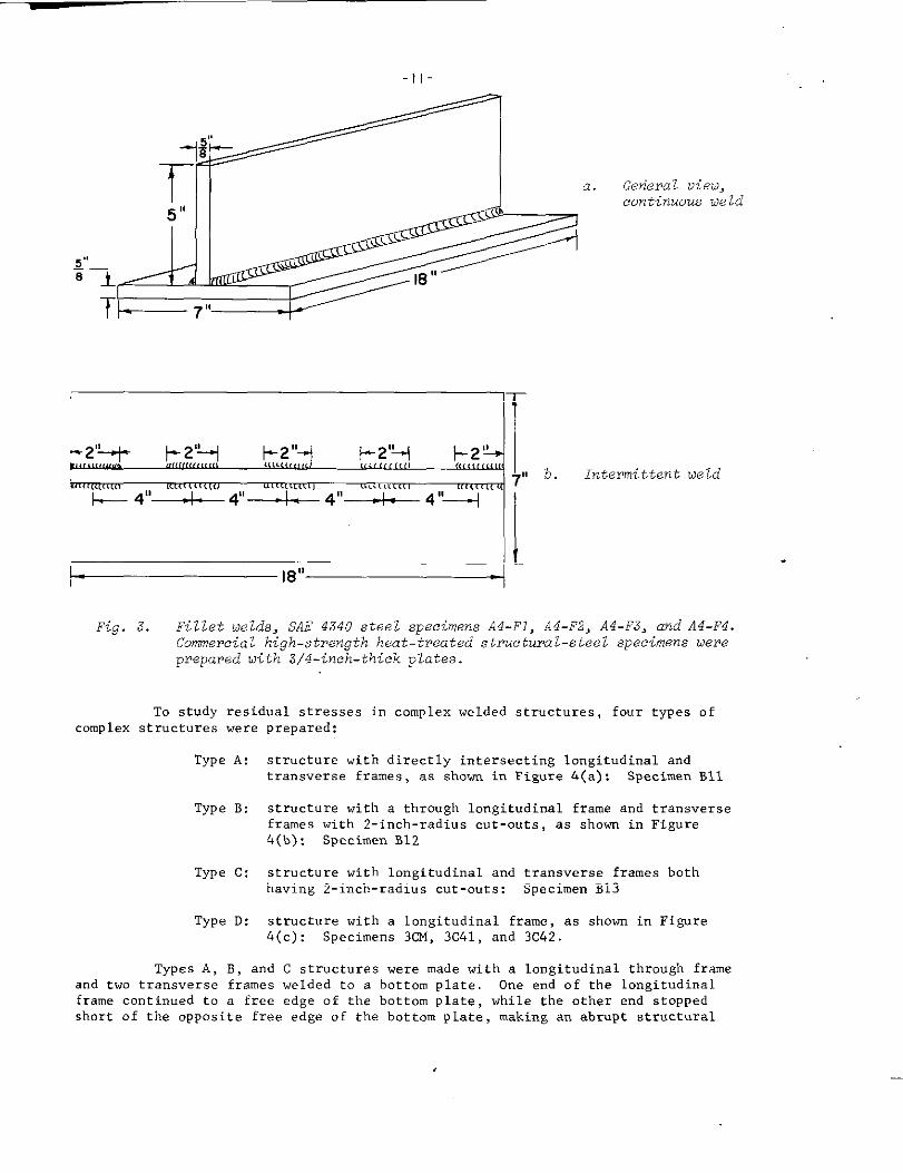
Figure 3 shows fillet welds made in SAE 4340 steel. The followings>ecimens were
(1)
prepared:
Heavy, continuous welding (Specimen A4-F1)
—
L---L=’LA
16“
a. Slit-Grmve Weld
~
,+8” I 8 -
-1o-
Section A-A
p 60”-+
D,~g
Joint preparation fw 3/4-inch-thick plate, Specimens PB-l,
PB-2, C2, P4-I
Joint preparation
Fig. 2. Slit -
groove ueld,
cross - butt
joint, and
circular -
groove LIeld.
b. Cross- Butt Joint, Specimen B 23
Ssction B-B
@&l
Joint preparation
c. Cimulor ‘Grwe (3 inches in diameter) Weld, Specimen 032
(2) Light, continuous welding (Specimen A4-F2)
(3) Heavy, intermittent welding (Specimen A4-F3)
(4) Light, intermittent welding (Specimen A4-F4)
The heavy welds were made in six passes, while one pass was used to make the lightweld. Figure 3(b) shows the intermittent weld; 2-inch-long welds with a 4-inchpitch. A fillet weld also was prepared with the conunercialhigh-strength structuralsteel plate 3/4 inch thick, Specimen AT-F1. The specimen was welded with theheavy, continuous technique”.
-11-
+ -v~ General v’ieu,
5 “
Z,,a“ con’%nuousue’d
83
5’. Intermittent Meld
44-F2. A4-F3. and A4-F4.Fig. 3. Fillet Uelds, SAE 4340 steel specimens A4-F1.Commeroia L high-strength heat-treated structura l-st;e1 spe;imens Mereprepared with 3/4-inch-thick plates.
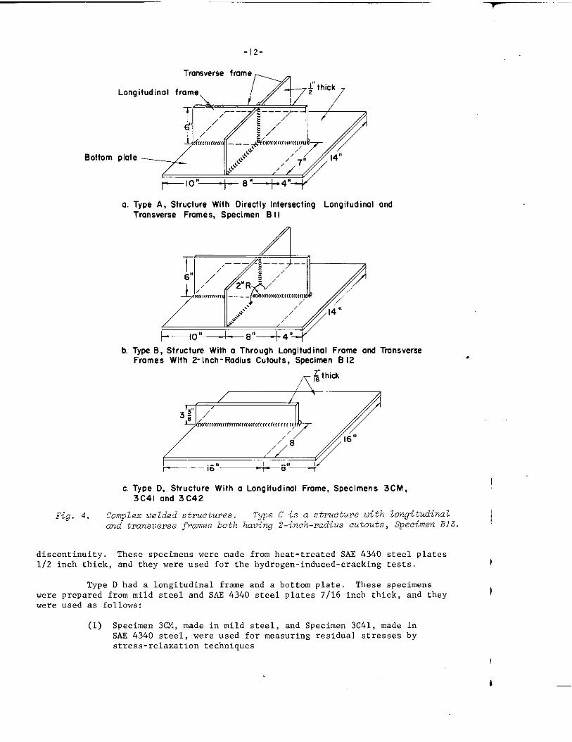
To study residual stresses in complex welded structures, four types ofcomplex structures were prepared:
Type A:
Type B:
Type C:
Type D:
structure with directly intersecting longitudinal andtransverse frames, as shown in Figure 4(a): Specimen Bll
structure with a through longitudinal frame and transverseframes with 2-inch-radius cut-outs, as shown in Figure4(b): Specimen B12
structure with longitudinal and transverse frames bothhaving 2-inch-radius cut-outs: Specimen B13
structure with a longitudinal frame, as shown in Figure4(c): Specimens 3cM, 3c41, and 3c42.
Types A, B, and C structures were made with a longitudinal through frameand two transverse frames welded to a bottom plate, One end of the longitudinalframe continued to a free edge of the bottom plate, while the other end stoppedshort of the opposite free edge of the bottom plate, making an abrupt structural
Bottom
-12-
Trmwerse frame
Longitudinal frame
plate
*IO”+ 8“+4”
a. Type A, Structure With Directly Intersecting Longitudinal ondTransverse Frames, Specimen B II
/’
+10’’+ B’1+4°
b. Type B, Structure With a Through Longitudinal Frame and TransverseFrames With 2-inch-Radius Cutouts, Specimen B 12 .
c. Type D, Structure With a Longitudinal Frame, Specimens 3CM,I
3C41 and 3C42
Fig. 4. Complex ue lded struetures. Type C is a structure oith longitudinal1and transverse frames both having 2–inch-radius cutouts, Specimen B13.
I
discontinuity, These specimens were made from heat-treated SA.E434o steel plates1f2 inch thick, and they were used for the hydrogen-induced-cracking tests. I
Type D had a longitudinal frame and a bottom plate. These specimenswere prepared from mild steel and SAE 4340 steel plates 7/16 inch thick, and they !
were used as follows:
(1) Specimen 3CM, made in mild steel, and Specimen 3c41, made inSAE 4340 steel, were used for measuring residual stresses bystress-relaxation techniques
-13-
(2) Specimen 3c42, made in SAE 4340 steel, was used for the hydrogen-induced-cracking test.
Bead-on-plate specimens were prepared from l/2-inch-thick SAE 4340steel plates oil quenched and tempered at 500 F, The specimens were 3-1/2 by16 inches, and a 9-inch-long section i“ the center of the specimen was reduced tol/4-inch thickness by grinding before welding. After weld beads were laid on
both surfaces of the reduced section, the specimens were loaded in a testingmachine to different stress levels. The objective of this phase of research was
to determine whether hydrogen-induced cracking is caused by residual stresses orby plastic strains. Since high-tensile longitudinal residual stresses exist inregions near the weld, additional plastic deformation occurs in the regiom whena tensile load in the longitudinal direction is applied to the welded specimen.However, the magnitude of residual stress decreases because of this additionalplastic strain. This phenomenon is known as “mechanical stress relieving”. Ifhydrogen-induced cracking is stmsitiws to plastic strain, more cracking shouldoccur in mechanically stress-relieved specimens than in as-welded specimens. Ifhydrogen cracking is se”siti”e to stress, there should be less cracking inmecha”ice.lly stress-relieved specimens.
Welding Procedures, Most specimens were welded with covered electrodes.The electrodes used for each type of steel were as follows:
Mild steel: E601o (E7016 electrodes also were used on somespecimens)
HY-80 steel: E1OO16 and E11018 .
Commercial high-strength structural steel: E1OO16 and E12015
SAE 4340 steel: E15016
Several different diameters of electrodes, ranging from 1/8 inch to 3/16 inch wereused. Each specimen was welded with suitable-size electrodes under the optimumconditions for the joint design and thickness. For example, typical weldingconditions for E15016 electrodes were about 120 amperes for l/8-inch-diameterelectrodes, about 150 amperes for 5/32-inch-diameter electrodes, and about 170amperes for 3/16-inch-diameter electrodes,
Several specimens were welded with s“bmei-ged-arc, inert-gas metal-arc(MIG), and the Narrow-Gap welding process. The Narrow-Gap process is a new auto-matic gas-shielded metal-arc welding process developed at Battelle for theBureau of Ships (Contract No. NObs-86424) (12) Very narrow welds--say a l/4-i”ch-vide square-butt weld for a Z-inch-thick plate--cm be made by this new process,
Two mild-steel specimens (FM5 a“d FM6) were welded with the submerged-arc process as follows:
Electrode: mild steel, 5/32 inch in diameter
Welding cmditions: welding current, 55o amperes; arc vo:.tage, 30volts; travel speed, 17 ipm for backingpasses and 25 ipm for the finishing pass;contact-to-work distance, 314 inch.
.
-14-
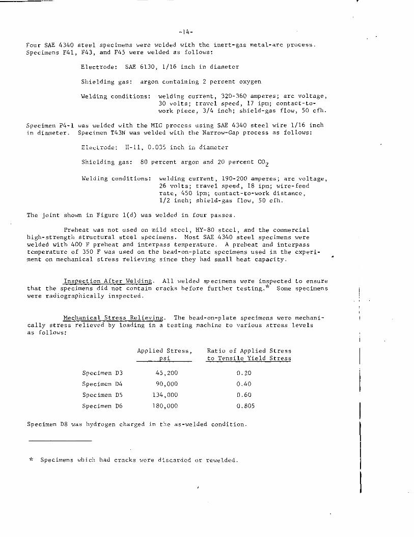
Four SAE 4340 steel specimens were welded with the inert-gas metal-arc process.Specimens F41, F43, and F45 were welded as follows:
Electrode: SAS 6130, 1/16 inch in diameter
Shielding gas: argon ccmtaining 2 percent oxygen
Welding conditions: welding current, 32O-36O amperes; arc voltage,30 “oIts; tra”el speed, 17 ipm; contact-to-vmrk piece, 3/4 inch; shield-gas flow, 50 cfh.
Specimen P4-1 was welded with the MIG process using SAS 4340 steel wire 1/16 inchin diameter. Specimen T43N was welded with the Narrow-Gap process as follows:
Electrode: H-n, 0.035 inch in diameter
Shielding gas: 80 percent argon and 20 Percent C02
Welding ccmditiom: welding current, 190-200 amperes; arc “oltage,26 volts; travel speed, 18 ipm; wire-feedrate, 450 ipm; contact-to-work distance,1/2 inch; shield-gas flow, 50 cfh.
The joint shown in Figure l(d) was welded in four passes
Preheat was not used on mild steel, HY-80 steel, and the commercialhigh-strength structural steel specimens. Most SAR 4340 steel specimens werewelded with 400 F preheat and interpass temperature. A preheat .md interpasstemperature of 350 F was used on the bead-on-plate specimens used in the experi-ment on mechanical stress relieving since they had small heat capacity.
.
Inspection After Welding. All welded specimens were inspected to ensurethat the specimens did not contain cracks before further testing.+ Some specimenswere radiographically inspected.
Mechanical Stress Relieving. The bead-on-plate specimens were mechani-cally stress relie”ed by loading in a testing machine to “arious stress levelsas follows:
Applied Stress, Ratio of Applied Stresspsi to Tensile Yield Stress
Specimen D3 45,200 0.20
Specimen D4 90,000 0.40
Specimen D5 134,000 0.60
Specimen D6 180,000 0.805
Specimen D8 was hydrogen charged in the as-welded condition
* Specimens which had cracks were discarded or rewelded
-15-
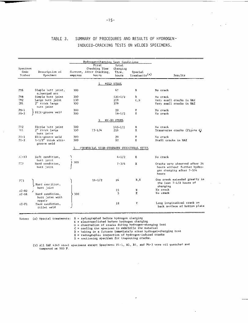
TABLE 3. SUMMARY OF PROCEDURES ANO RESULTS OF HYOROGEN -
INOUCEO-CRACKING TESTS ON WELOEO SPECIMENS.
HydroRe.-Charging Test ConditionsFir,, Total
5pecimen Checking TimeCode
chargingDescription of Current, After Cracking T%.. ,
X.nlber ‘pee’al (a)specime. a.”peres ho.~s hours ‘meatr”e.ts Results
FX8IX231
?B-1?B-2
—..
.-:—.
~:.:.l?.+*
.:.:-B3
72
X3
.7-B2
.:.7-B1
.;T-FI
Simple butt joint,submerged arc
Simple butt joint
Large butt j.i”t
2,, thick Iaree
butt joint
} slit-groove weld
Simple butt joint2,’thick largebutt jointSlit-groove weld1-1/2,,thick 81it-groo.,e weld
Soft condition,butt joint
Hard condition,butt joint
1“Hard condition,
butt jo<”t
./Hard mndit ion,butt joint withrepair
Hard c..diti.”,fillet weld
1. MILD STEEL
300 47 R
300130350
126-1/2 R219 C,s379
300 20 E300 18-1/2 E
2. HY-80 STEEL
300 140-1/2350 73-1/4 216 !
300300
20 E22 E
~rQFUiERCIAL HIGI-STRENGTH STRUCTURAL STEEL
1
4-1/2 E
300 7-3/4 x
) 16-1/2 2L R,X
i
300
15 E5 E
18 E
NO crack
No crackVery small cracks in K4ZVery small cracks in HAZ
No crackNo crack
N. crackTransverse cracks (Fi&re Q
N. crackSmall cracks in HAZ
No crack
Crack, were obser.ed after 24hours without further hydr.-ge” .hargi”g after 1-314hours
0.. crack extended greatly in
the last 7-1/2 hours of
charging
N. crack
No crack
Lmg longitudinal crack ..back surface of bottom P1ate
sates: (a) Special treatments: R = radiographer before hydrogen chargingE = electr.apolished before hydrogen charging0 = observation of cracks during hydrogen-charging testC = m.li.g the specimen to embrittle the materialB = baking i“ a furnace immediately after hydrogen-charging testX = radiographic inspection of hydrogen-induced cracksS = sectioning specimen for inspecting cracks.
(b) All WE 4340 steel specimens except specimens P4-1, R5, R4, and P4-3 were oil quenched andtempered at 500 F.
-16-
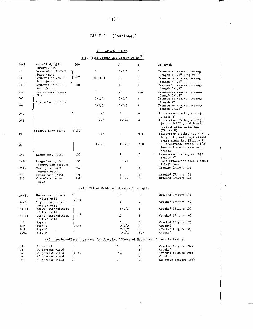
TABLE 3. (Continued)
4. SAE4340 STEEL
b-l. Butt Joints and Groove Welds (b)
E
0
0
E
R,X
x
x
o
0
O,B
P4-1
R5
K4
P+ 3
rti5
F47
F49
As rolled, ,litwin..., MIG
Tempered at 1000 F,butt joint
TemPered at 750 F,butt jointTernPeredat 600 Fbutt jointSimple butt joint,MIG
1
300 14
2 6-3/4
180 About ~ ~
300 1
No crack
Transverse cracks averagelength 1-1/4’,(Figure 7)
Transverse cracks, averawlength 1-1/4’
‘Transversecracks> averageIermth 3-1/2-,
4
2-314
4-1[2
7
2-314
Tran:v, rsecracks, averagelength 2-1/2’!
Transverse cracks, averagelength 2,,
Transverse cracks, averagelength 2-112,$
‘transversecrack,, avera~elength 2,,
Transverse cracks averagelength 2-1/2,,,and 10.gi-t.dinal crack along H.4Z(Figure 8)
Transverse cracks , average .length 3,,, and longitudinalcrack .1..8 tlAZ (Figure 9)
0., transverse cm.ck, 1-1/2,,long and short transfereecrack,
Transverse cracks average
JSimple butt joints4-112
041
042
3/4
4/5
3
Z-l/&
simple butt joint 1505/6R2 2
1-1/6 1-1/3R3
‘U.2
T43N
E21-:
Large butt joint 130
130
250
270150
1
1/4
5
:-1/2
length 4t~Short transverse cracks about1-1/29’long
Cracked (Fi8um 10)
Large butt joint,N.rmw-GaP ProcessButt joint withrepair weldsCross-butt j.intCircular-gr.o”eweld
cracked (Figure 11)Cracked (Figure 12)
B23B32
4-2. Fillet Welds and Complex Str.cture$
116 E
3006 E
1
6-1/2 E
300 15 E
Cracked @iwre 13)
Cracked (Figure 14)
Cracked (Figure 15)
Cracked (Figure 16)
A4-F1 Hea”y, wmti..msfillet weld
AL-F2
A4-F3
Light, mntinuo.sfillet weld
Heavy, intermittentfillet weld
Light, intermittentfillet weld
Cracked (Fi~”re 17)B1lB12B133C42
Type ATYP. BType cTyPe D
)350
3 E2-1/2 E Cracked2-1/2 E Cracked (Fig,,..18)1-112 B2X Cracked
4-3, Bead-o.-Plate Soecime.s for Studying Effect. of Mechanical Stress Relieving
A. welded
1 1
E20 percent yield
Cracked (Figure 19.)E Cracked
LO percent yield 75 6 E60 percent yield
Cracked (Figure 19b)Cracked
80 percent yield : No crack (Figure 1’3.)
D8D3Di)D5D6
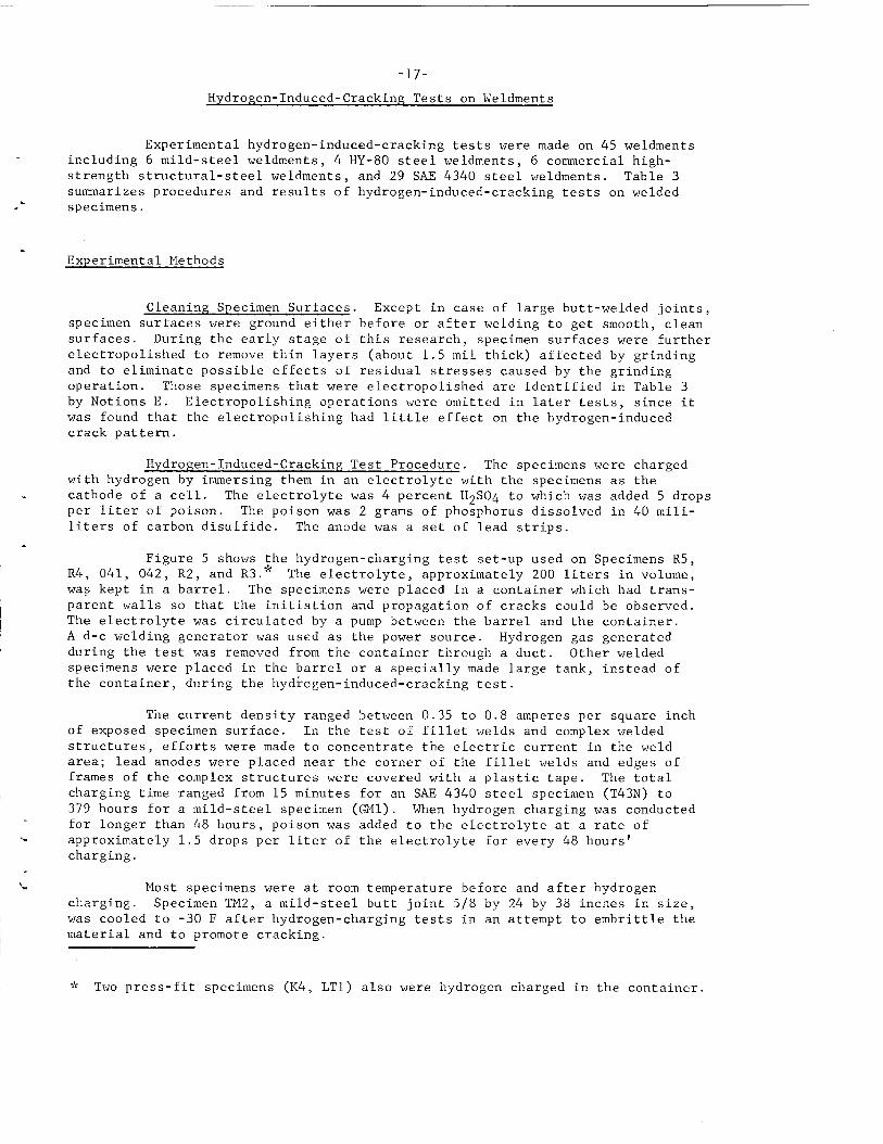
-17-Hydro~en-Induced-Crackin~ Tests on Weldments
.
.
.
I.
.
Experimental hydrogen-induced-cracking tests were made on 45 weldmentsincluding 6 mild-steel weldments, 4 HY-80 steel weldments, 6 commercial high-strength structural-steel weldments, and 29 SAE 4340steelweldments. Table 3summarizes procedures and results of hydrogen-induced-cracking tests on weldedspecimens.
Experimental Methods
Cleaning Specimen Surfaces. Except in case of large butt-welded joints,
specimen surfaces were ground either before or after welding to get smooth, cleansurfaces. During the earlystageof this research, specimen surfaces were furtherelectropolished toremovethinlayers(about1.5milthick)affectedbygrindingandtoeliminatepossibleeffectsofresidualstressescausedbythegrindingoperation.ThosespecimensthatwereelectropolishedareidentifiedinTable3byNotionsE. Electropolishingoperationswereomittedinlatertests,sinceitwasfoundthattheelectropolishinghadlittleeffectonthehydrogen-inducedcrackpattern.
Hydrogen-Induced-CrackinyTestProcedure.Thespecimenswerechargedwithhydrogenbyimmersingtheminanelectrolytewiththespecimensasthecathodeofa cell.Theelectrolytewas4 percentH2S04towhichwasadded5 dropsperliterofpoison.Thepoisonwas2 gramsofphosphorusdissolvedin40mill-ilitersofcarbondisulfide.Theanodewasa setofleadstrips.
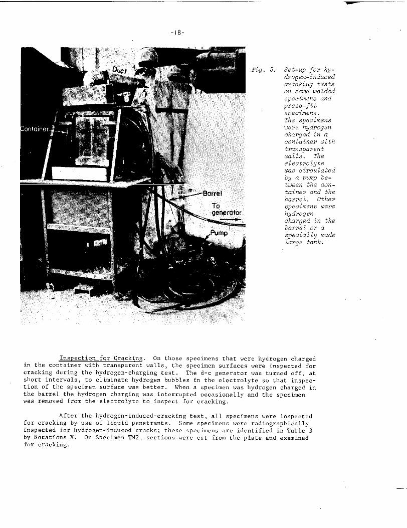
Figure5 showsthehydrogen-chargingtestset-upusedonSpecimensR5,R4,041,042,R2,andR3.’”Theelectrolyte,approximately200litersinvolume,waskeptina barrel.Thespecimenswereplacedina containerwhichhadtrans-parentwallssothattheinitiationandpropagationofcrackscouldbeobserved.Theelectrolytewascirculatedbya pumpbetweenthebarrelandthecontainer.A d-cweldinggeneratorwasusedasthepowersource.Hydrogengasgeneratedduringthetestwasremovedfromthecontainerthrougha duct.Otherweldedspecimenswereplacedinthebarrelora speciallymadelargetank,insteadofthecontainer,duringthehydrogen-induced-crackingtest.
Thecurrentdensityrangedbetween0.35to0.8amperespersquareinchofexposedspecimensurface.Inthetestoffilletweldsandcomplexweldedstructures,effortsweremadetoconcentratetheelectriccurrentintheweldarea;leadanodeswereplacednearthecornerofthefilletweldsandedgesofframesofthecomplexstructureswerecoveredwitha plastictape.Thetotalchargingtimerangedfrom15minutesforanSAE4340steelspecimen(T43N)to379hoursfora mild-steelspecimen(GM1).Whenhydrogenchargingwasconductedforlongerthan48hours,poisonwasaddedtotheelectrolyteata rateofapproximately1.5dropsperliteroftheelectrolyteforevery48hours’charging.
Mostspecimenswereatroomtemperaturebeforeandafterhydrogencharging.SpecimenTM2,a mild-steelbuttjoint5/8bywascooledto-30F afterhydrogen-chargingtestsinanmaterialandtopromotecracking.
$:Twopress-fitspecimens(K4,LT1)alsowerehydrogen
24by38inchesinsize,attempttoembrittlethe
chargedinthecontainer.
—
-i8-
F 5. Set-up for hy-drogen-inducedcracking testson some ue lded
specimens andpress-fit
specimens.The specimensuere hydrogencharged in acontainer oithtransparenttialls. Theelectrolyteuas circulatedby a pump be-twen the cOn-tainer and thebarrel. Other
swimens Oerehydrogencharged in thebarrel or a
speciallY madelarge tank.
Inspection for Cracking, On those specimens that were hydrogen chargedin the container with transparent walls, the specimen surfaces were inspected forcracking during the hydrogen-charging test The d-c generator was turned off, atshort intervals, to eliminate hydrogen bubbles in the electrolyte so that inspec-tion of the specimen surface was better. When a specirrm was hydrogen charged inthe barrel the hydrogen charging was i“terr”pted occasionally and the specimenwas removed from the electrolyte to inspect for cracking.
After the hydrogen-induced-cracking test, all specimens were inspectedfor cracking by “se of liquid penetrants. Some specimens were radiographicallyinspected for hydrogen-induced cracks; these specimem are identified in Table 3
by Notations X. On Specimen ‘IT42,sections were cut from the plate and examinedfor cracking.
-19
..”’ “.’..”,,..,
t’
)>
,,
Baking Specimens After Hydrogen Char~ing
During this Rc?s.arch, it was found tt,at hydrogen-induccd cracks often extended without furthert~ydrogcncharging a“d the extr.ndedcracks causedmisinterpretation of the residual-stress pattern.An i“vcstigation was made of the effectivenessof taking the specimens after the hydrogen charging‘to remove.hydrogen and to prevent the delayedfracture Immediately after bydrog.n-charging
operations were completed, two specimens (R2 and R3)
were pl,aced in a furnace at 400 F for 2 hours on
Specimen R2 and for 1 I,our o“ Specimen R3. Specimens
‘T42and 3C62 also were bakc!dat 400 F for 2 hours,
Exp.rime,ltalR,,,,]t,, Part 1 Effects of rYp~, ofIleatTrcatrnent, and IPlate Thickness on Hydrogen–
induced-Cracking Test Results
steel,
Results of tlvdroze”–induc.ed–crackinc,., .tests on welded spc,.imens arc,.summarized in Table 3.‘The,pccim,n, w,,, prepa,cd from four types ofst,e], ~itb “:iriousstrengtlb 16.V~lS ~. fOll OWS :
-20-
Mild steel (as rolled)HY-80 steel (quenched and tempered)Cormnercial high-strength structural steel (treated
to the “soft condition”)Commercial high-strength structural steel (treated
to the “hard condition”)SAE 4340 steel (as rolled).SAF 4340 steel (oil quenched and tempered at 1000 F)SAE 4340 steel (oil quenched and tempered at 75o F)SAS 4340 steel (oil quenched and tempered at 600 F)SAE 4340 steel (oil quenched and tempered at 500 F)
ApproximateTensileStrength,
psi
75,000
100,000120,000
150,000
150,000175,000220,000240,000260,000
Number ofSpecimensTested
641
5
1111
25
Mild Steel. Six mild-steel specimens 1/2 to 2 inches thick were chargedwith hydrogen up to 379 hours In order to promote cracking, the followingvariations were investigated: .
(1) Large welds were made in hea”y plate to obtain maximum residualstresses
(2) Long time hydrogen charging
(3) Cooling specimens after hydrogen charging to embrittle them2terial.
For example, Specimen TM2 (a simple butt joint 5/8 by 24 by 38 inches in size)was hydrogen charged for 1 hour, removed from the electrolyte and cooled to -300 Ffor 1 hour. The test was repeated with the charging time increased to z hours.Charging was resumed and continued for an additional 216 hours and then the
specimen was cooled to -30 F for 4 hours. No cracks were visible on the surfaceafter these operations Sections were cut from the plate and examined for ci-ack-ing; very small cracks were found in the heat-affected zone. Very small cracksalso were found in the heat-affected zone of Specimen @fl (a simple butt joint2 by 16 by 20 inches in size) hydrogen charged for 379 hours No cracks werefound i“ 4 other specimens hydrogen charged up to 126-1/2 hours,
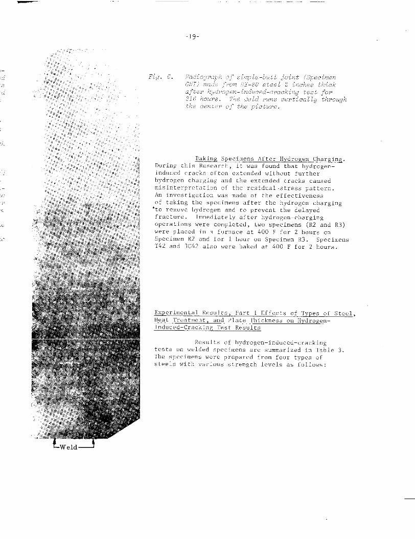
HY-80 Steel. Four HY-80 steel specimens 1/2 to 2 inches thick werecharged with hydrogen up to 216 hours. Figure 6 shows a print of a radiograph ofa 2-inch-thick butt joint (Specimen GH1) after hydrogen charging for 216 hours.Transverse cracks were obtained in the weld metal. Some cracks appeared to bequite deep , b“t the cracks did not appear to penetrate into the base plate.Small cracks were observed in the heat-affected zme of a l-1/2-inch-thick weld(Specimen PH-2) , but no cracks were found in Specimens FH2 a“d PH-1.
ConnnercialHigh-Strength Structural Steel. A hydrogen-induced-crackingtest was conducted on one weldment made in the cmmnercial high-strength strwturalsteel heat treated to the “soft co”ditionvv. No cracks were observed afterhydrogen charging for 4-1/2 hours
-21-
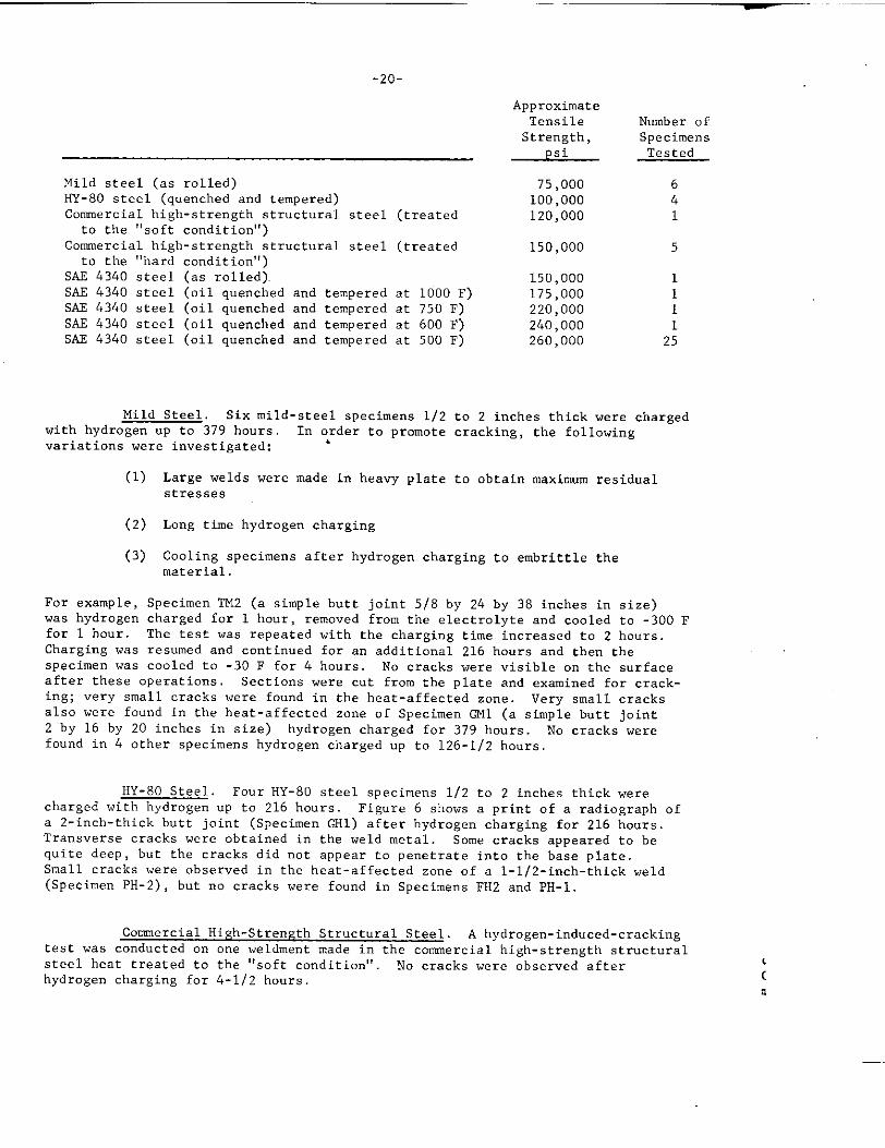
Hydrogen-induced-cracking tests werecommercial high-strength structural steel heatCracks were found in three weldtnent. Severalmetal after charging for 7-314 hours in a butt
,madeon five weldrnents of tk[etreated to the hard condition.cracks were found i“ the weldjoint (Specimen FT’2), and.some,of
-22
them extended into the base P late without further charging. A few short crackswere found after 16-1/2 hours of charging another butt joint (Specimen FT3) , andone of them extended to tbe edge of tbe specimen after charging for 24 hours Alongitudinal crack was found in the back surface of the bottom plate in tbe filletweld (Specimen AT-F1).
SA2 4340 Steel. A hydrogen-induced-cracking test was conducted on one..mldmentmade in SAE 4340 steel in the as-rolled condition, No cracks wereobserved after charging for 14 hours.
Se”eral very short cracks in the heat-affectecl zone were observed afterhydrogen charging for 2 hours cm Specimen R5 made in SAS 4340 steel oil quencheda“d tempered at 1000 F. The initial cracks grew and the number 01 cracks increasedwhen hydrogen charging was continued. A system of transverse cracks, as shown i“Figure 7, was obtained after hydrogen charging for 6-3/4 hours One pair of cracksi“ the central part of the specimen, shown in Figure 7, grew quite long afterhydrogen charging was stopped.
On Specimen R4 made in SAE 4340 stc!eloil quenched aml tempered at750 F, a set of cracks, about 1-1/2 inches long o“ both sides of the crack (thecrack in one side was curved) , was observed after hydrogen charging [or 30 minutesA nwnher of “cry short cracks vcre formed i“ the beat-affected zone while thehydrogen-induced-cracking test was cmtinucd. The crack pattern obtained afterhydrogen charging for 6 hours was similar to tt,atshown in Figure 7. A Pair Oflong transverse cracks in the central part of the specimen grew after hydrogencharging was stopped.
A system of transverse cracks was found after 1 hour of hydrogen chargingof Specimen P4-3 made in SAE 4340 steel oil quenched and tempered at 600 F. Thecra:k pattern was similar to that obtained o“ butt joints made in SAE 4340 steeloil quenched and tempered at 500 F.
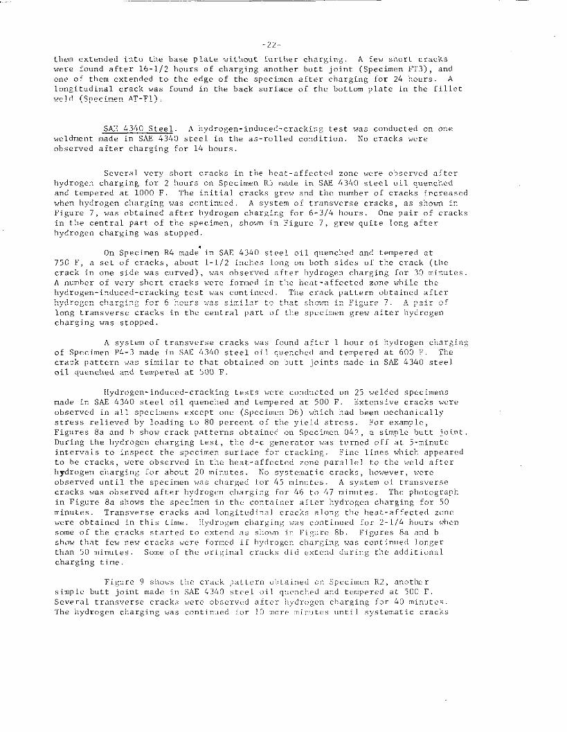
Hydrogen-induced-cracking tests were conducted on 25 welded speci”ensmade in SAE 4340 steel oil quenched and tempered at 500 F. Extensive cracks wereobserved in all specimens except me (Specimen D6) which had been mechanicallystress relie”ed by loading to 80 percent of the yield stress. For example,Figures 8a a“d b S11OWcrack patterns obtained on Specim.n 042, a simple butt joint.During the I,ydroge” charging test, the d-c generator was turned off at 5-minuteintcrv.is to inspect the specimen surface for cracking. Fine lines which appearedto be cracks , were observed in the beat-affected zone parallel to the weld afterhydrogen charging for about 20 mi””tes. No systematic cracks, Ilowever,wereobserved until the specimen ~.,ascharged for 45 mi”utcs. A system “f trmswersecracks was observed after I,ydr”gc” charging for 46 to 47 minutes ‘rh,photographi“ Fig”r. 8a shows the specimen in the container after hydrogen charging for 50minutes Transverse cracks and longitudinal cracks along the heat-affected zonewere obtained in this time. llydroge” charging was continued for 2-1/4 hours wt,ensome of the cracks started to cxte”d as sho,m in Figure 8b, Figures 8a a“d bshow that few new cracks were formed it hydrogen charging was continued longerthan 50 minutes. Some of the original cracks did extend during the additionalcharging time.
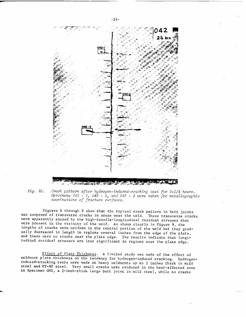
Figure 9 shows the crack pattern obtained on Specin,cnR2, anotbersimple butt joint maclc i“ SAE 4340 steel oiI qucncl,ed and tempered at 500 F.Several trans”ersc cracks wcrr obser”c,d after I,ydrogc,ncharging for 40 min.tcs.The hydrogen charging was co”ti””ed ior 10 n,oreminute,s until systematic cracks
_—.
Fig. 8a. Crack pattern after hgdrogen–induce d-cracking test for 50 minUte.5.Crack patterns observed m a zimple-butt [jointmade from SAE 4340steel oil quenched and temperea at S00 ? (L@cimen 042).
were obtained, then the specimen was placed in a furnace at 400 F for 2 hoursto allow hydrogen to diffuse from the specimen. Transverse and longitudinal
cracks were obtained in the heat-affected zone. No appreciable change of crackpattern was observed after baking. Apparently, sufficient hydrogen was removedfrom the specimen to stop delayed cracking.
The above mentioned experimental results clearly show tl.atthe tendencyof a weldment for hydrogen-induced cracking is affected by the properties of thebase plate. As the tensile strength of the base plate increases , more extensivecracks are formed in a shorter period of hydrogen charging.
.
-24-
042-1
—
--l?
.-.
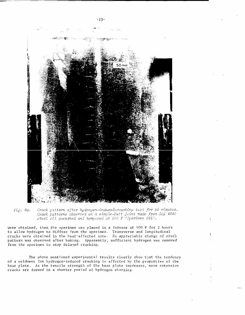
Fig. 8b. Crack pattern after hydrogen-induced-cracking test for 2-1/4 hours.Specimens 042 - 1, 042 - 2, and 042 - 3 tieretaken for metal lographicexaminations of fracture surfacea.
Figures 6 through 9 show that the typical crack pattern in butt jointswas composed of transverse cracks in areas near the weld. These transverse crackswere apparently caused by the high-tensile-longitudinal residual stresses thatwere present in the vicinity of the weld, As shown clearly i“ Figure 9, thelengths of cracks were uniform in the central portion of tbe weld but they grad-ually decreased in length in regions several inches from the edge of the plate,and there were no cracks near tbe plate edge. The results indicate that longi-tudinal residual stresses are less significant in regions near the plate edge.
Effect of Plate Thickness. A limited study was made of the effect ofweldment plate thickness on the tendency for hydrogen-induced cracking. Hydroge”-induced-cracking tests were made on heavy veldments up to 2 inches thick in mildsteel and HY-80 steel. Very small cracks were produced in the heat-affected zonein Specimen GM1, a 2-inch-thick large butt joint in mild steel, while no cracks
-25-
..-!jOmh
I(hat)
,,wreobserved in other mild-steel specimens except Specimen TM2 which was cooledto -30 F after hydrogen charging. on HY-80 steel specimens , cracks were foundin Spe.irnc”sGHl (2 inches thick) and PH-2 (1-1/2 inches thick) , while “o crackswere observed in other specimens 1/2 inch thick. These results showed thatcracks were more pronounced in heavy weldments than in ,.weldn,entsmade from tbi””crpl.atcs, The effect of plate thickness , however, was not great
Zxperirnental Results , Part 2 Hydrogen-Induced Crack Patterns Obtained on Various‘!:eldmentsPrepared in Heat-Treated SAE 4340 Steel
IIydrogen-induced-cracking tests were conducted o“ 25 vmldmcmts made in
SAE 4340 steel oil quenched and tempered at 500 F. Dffferent weldm.nt designs
a“d different welding procedures were used to produce a variety of residual-stressdistributions.
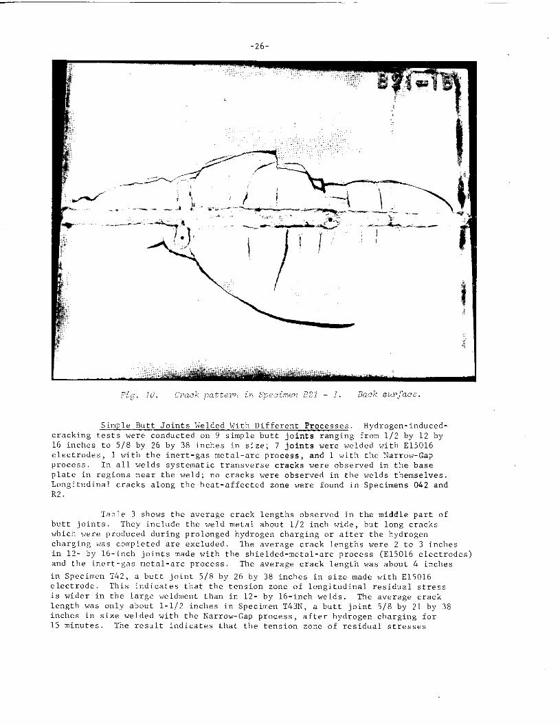
-26-
Simple Butt Joints Welded With Different Processes. Hydrogen-induced-
cracking tests were conducted on 9 simple butt joints ranging from 1/2 by 12 by
16 inches to 5/8 by 26 by 38 inches in size; 7 joints were welded with E15016
electrodes, 1 with the inert-gas metal-arc process, and 1 with the Narrow-Gapprocess. In all welds systematic transverse cracks were observed in the baseplate in regions near the weld; no cracks were observed in the welds themselves.Longitudinal cracks alcmg the heat-affected zone were found in Specimens O&2 andR2
Table 3 shows the average crack lengths observed in the middle part ofbutt joints. They include the weld metal about 1/2 inch wide, but long crackswhich were produced during prolonged hydrogen charging or after the hydrogencharRinE was completed are excluded. The averaze crack leneths were 2 to 3 inchesin 12- by 16-inch joints made with the shielded-metal-arc process (E15016 electrodes)and the inert-gas metal-arc process The average crack length was about 4 inches
in Specimcm T42, a butt joint 5/8 by 26 by 38 inches in size made with E15016electrode. This indicates that the tension zone of lo”gitudi”al residual stressis wider i“ the large weldrmmt than in 12- by 16-inch welds. The average cracklength was cmly about 1-1/2 inches in Specimen T43N, a butt joint 5/8 by 21 by 38inches in size welded with the Narrow-Gap process , after hydrogen charging for15 minutes, The result indicates that the tension zone of residual stresses
.
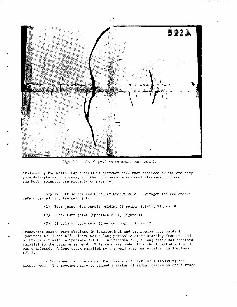
Fig. 11. Crack pattern in cross-butt joint.
produced by the Narrow-Gap process is narrower than that produced by the ordinaryshielded-metal-arc process , and that the maximum residual stresses produced bythe both processes are probably comparable.
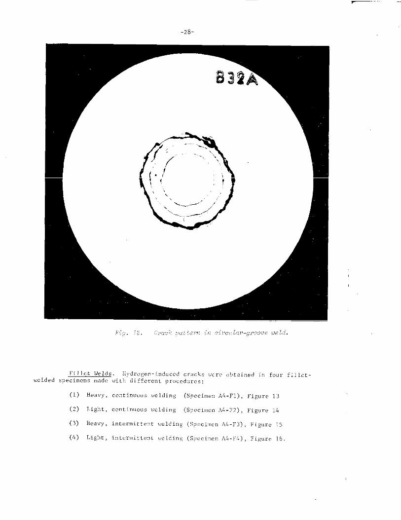
Complex Butt Joints and Circular-Groove Weld. Hydrogen-induced crackswere obtained in three weldments:
(1) Butt joint with repair welding (Specimen B21-1) , Figure 10
(2) Cross-butt joint (Specimen B23), Figure 11
. (3) Circular-groove weld (Specimen B32) , Figure 12.
Transverse cracks were obtained in longitudinal and transverse butt welds in\ Specimens B21-1 and B23. There was a long parabolic crack starting from one end
of the repair weld in Specimen B21-1. In Specimen B23, a long crack was obtainedparallel to the transverse weld. This weld was made after the Io”gitudi”al weldwas completed. A Io”g crack parallel to the weld also was obtained in SpecimenB21-1,
In Specimen B32, the major crack was a circular one surrounding thegroove weld, The specimen also contained a system of radial cracks on one surface
-28
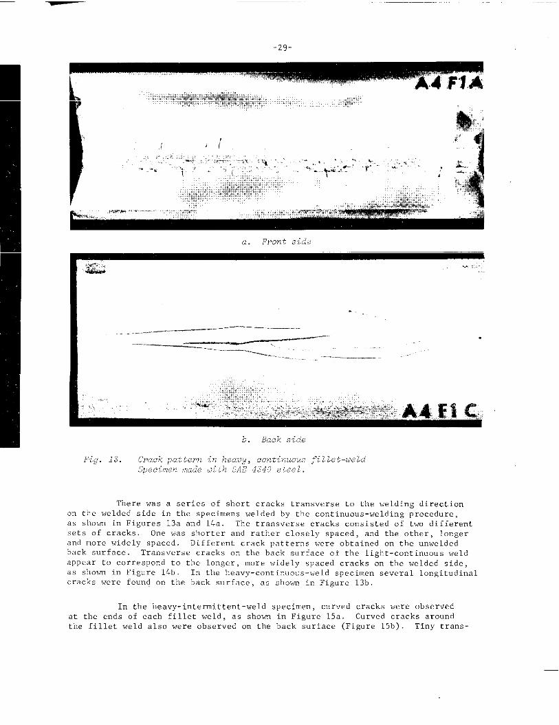
Fillet Welds. Ilj’drogen-ind. ced crack. !V.crc,obtained in four fi~~e~.
welded specimens made with different procedures:
(1) Heavy, continuous welding (Specimen A4-F1), Figure 13
(2) Light, continuous welding (Specimen A4-F2), Fig”r. 14
(3) Heavy, intermittent welding (Spcci,ncnA4-F3) , Figure 15
(4) Light, intermittent welding (Specimen A4-FI+), Figure 16.
-29-
[::- ;:2--;;GG&a:;m&$&:ix:.:.:::i. i“”..................*:.*
.,::,*!!JK:......
,L:
1
,,. ,.i F
,. :.,,.,.....-.-. “’.’”,i ~ ..’‘? ..’‘:,“.
.&_ ,,,,,[, ..“. ‘-” %-. &&:.<-’ r ~~ ~ : ,4 .;
.......... ...,, 4~&.. .......................
,,,,..,..,~’...,-,.-”:::W:::X:::::!::;:.,=,:;::::K:,,,,,,:g::x:!L,::.,,:. .........‘....”. :“’:;{:::..;{::’[ !. !yl.,,
,,,<,...,,ti::”:*F:: ‘ ,;..:,,..ax,:; ,!:
,..,. .,- ~~.”..-..-..W::.;;x;wr
.....’ ,..,!,, . :2<:!!!@’z?E-~’’f$~’ ~
a. Front side
. ..-
____________ .._._ —.————
-.. .---— —-””-——=.-l.:_,.:,”
...... .,,,,2,,::,,,;:,=,’.’,...............,.,,:,:..,.,..,.. ..... ............................
.,+.xE.xp,.Y,:, ,,y . . .. . . . . . . . . . . . . . . . . . ,; ;.,. ,, ‘.;::,:..,:,... .,
..::.:;....::,Vire.,b:.:,+~>.:$y$?:.~....>..,,:..,...:i.-.:~....-,.:
.....*.*.*%s~#f.dkii,g g Qj;
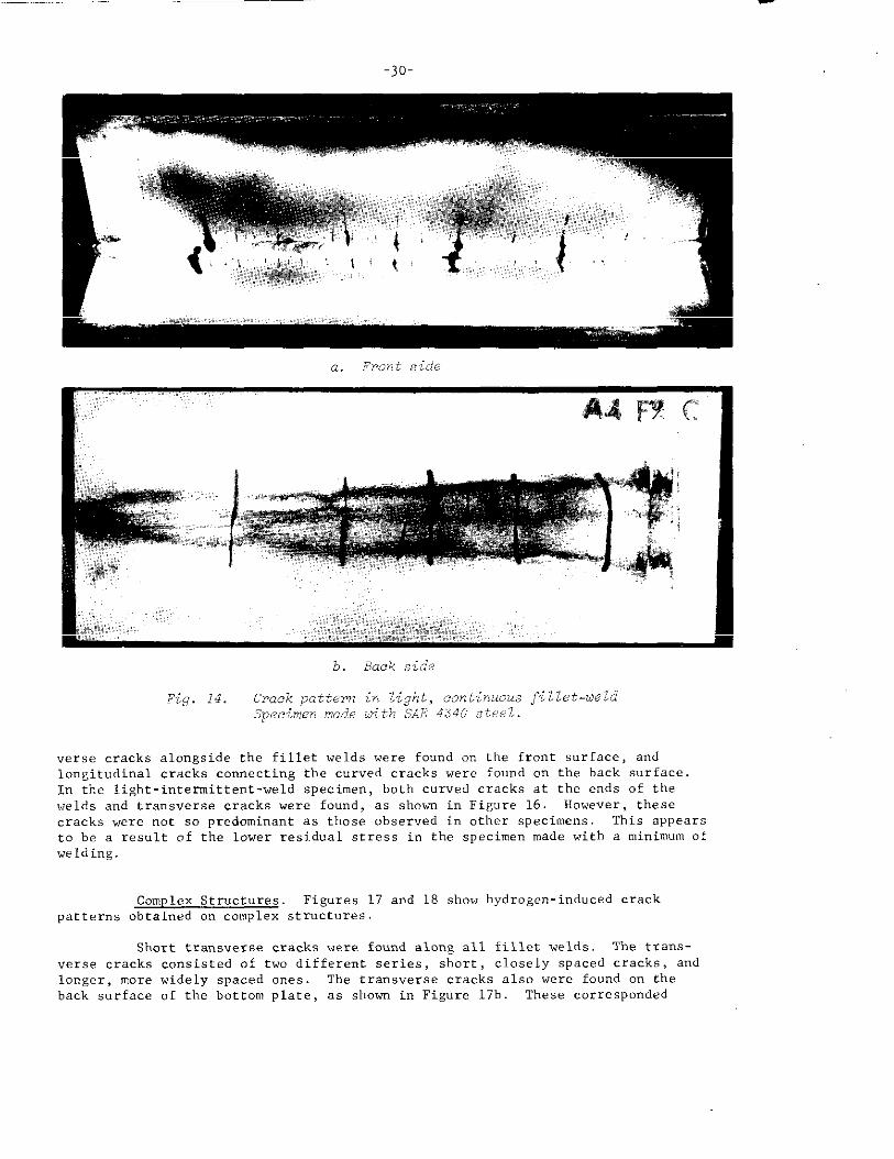
‘Therewas a series of shozt cracks transverse to the welding directionon the welded side in the specimens welded by the continuous-welding procedure,as slmvn in Figures 13a and 14.. The transverse cracks consisted of two differentsets of cracks, One was shorter and rather closely spaced, and the other, longerand more widely spaced. Different crack patteins were obtained cm the unwelded~ack surface Transverse cracks on the back surface of the light-continuous weld
appear to correspond to the longer, more widely spaced cracks on tbe welded side,as showm in Figure 14b In the heavy -continuous-xgeldspecimen se”eral longitudinalcracks were found o“ the back surface, as shown in Figure 13b.
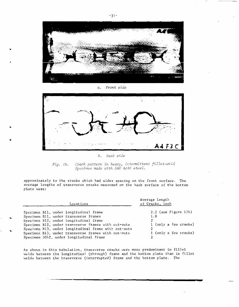
In tbe heavy-intermittent-weld specimen, curved cracks were observedat the ends of each fillet weld, as shown in Figure 15a. Cur”ed cracks aroundthe fillet weld also were observed on the back surface (Figure 15b) Tiny trans-
-30-
a. ,Fmnt side
b. Back side
Fig. 14. Crack pattern in light, continuous fi llet-ueldSjxcimen made tiithWE 4340 :;tee~Z.
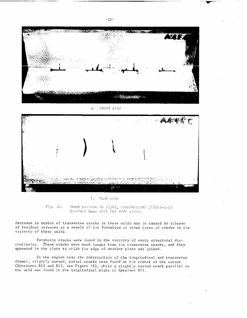
verse cracks alongside the fillet welds were found on the front surface, andlongitudinal cracks connecting the curved cracks were found on the back surface.In the light-intermittent-weld specimen, both curved cracks at the ends of the
welds and transverse cracks were found, as shown i“ Figure 16. However, these
cracks were not so predominant as those observed in other specimens. This appears
to be a result of the lower residual stress in the specimen made with a minimum ofwelding.
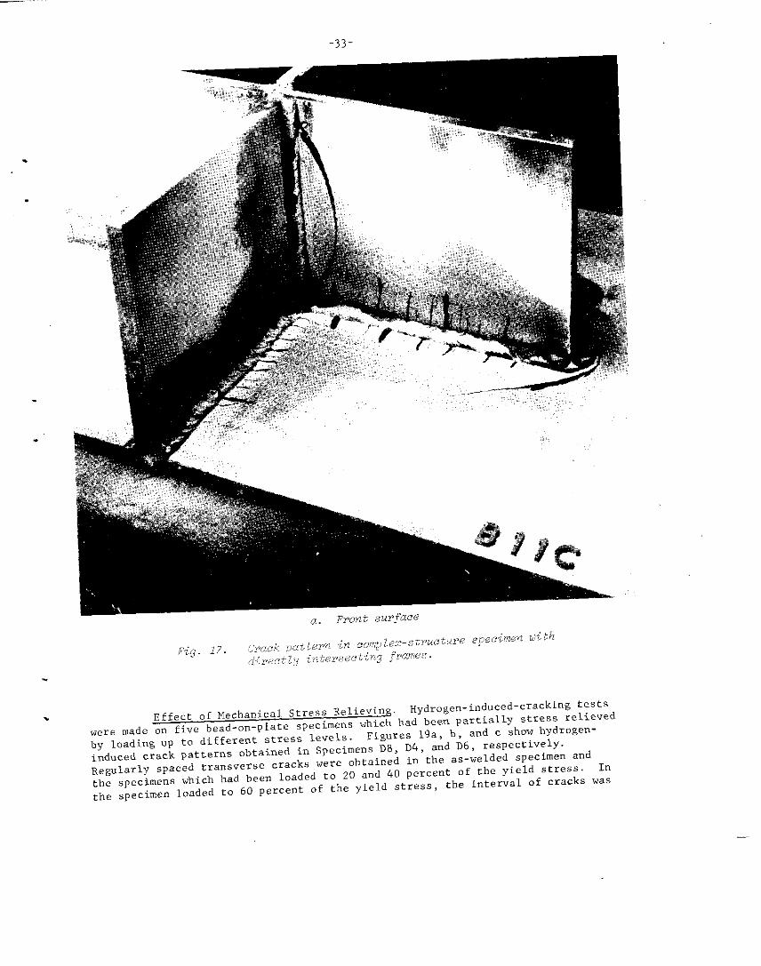
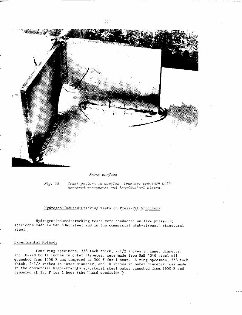
Complex Structures. Figures 17 and 18 show hydrogen-induced crackpatterns obtained on complex structures.
Short transverse c~acks were found along all fillet welds. The trans-
verse cracks consisted of two different series, short , closely spaced cracks, andlonger, more widely spaced ones. The transverse cracks also were found on the
back surface of the bottom plate, as shown in Figure 17b. These corresponded
.
-31-
.
a. Front side
.
,&
~. ,_..&:Sk,.......... .:..,.....
A4F3C
b. Back side
Fig. 15. Crack pattern in heavy, intermittent fillet-uei.dSpecimen made tiithSAfi:4.340steel.
approximately tO the cracks which had wider spacing on the front surface. The
average lengths of transverse cracks measured on the back surface of the bottomplate were:
Average Length
Locations of Cracks, inch
Specimen B1l, under longitudinal frame 2.2 (see Figure 17b)
. Specimen B1l, under transverse frames 1.8
Specimen B12, under longitudinal frame 2
Specimen B12, under transverse frames with cut-outs 1 (only a few cracks)
. Specimen B13, under longitudinal frame with cut-outs 2
Specimen B13, under transverse frames with cut-outs 1 (only a few cracks)
Specimen 3c42, under longitudinal frame 2
As shown in this tabulation, transverse cracks were more predominant in fillet
welds between the longitudinal (through) frame and the bottom plate than in filletwelds between the transverse (internpted) frame and the bottom plate. The
...-. ~-
-32-
.,.:s”.?.,’......,,...’.:..................,.,.~~.:iys,~.:.
.x’.. ...
-.ir,.n:,r’..,.,.:,,...., ,.
decrease in number of transverse cracks in these welds may be caused by releaseof residual stresses as a result of the formation of other types of cracks in thevicinity of these welds.
Parabolic cracks were found in the vicinity of every structural dis-continuity. These cracks were much longer than the transverse cracks, and they
appeared in the plate to whi.b the edge of another plate was joined.
In the regicm near the intersection of the Iongitudi”al a“d transverse
frames, slightly curved, radial cracks were found at the center of the cutout(Specimens B12 a“d B13, see Figure 18), while a slightly curved crack parallel tothe weld was found in the longitudinal plate in Specimen B1l.
-33-
.
.
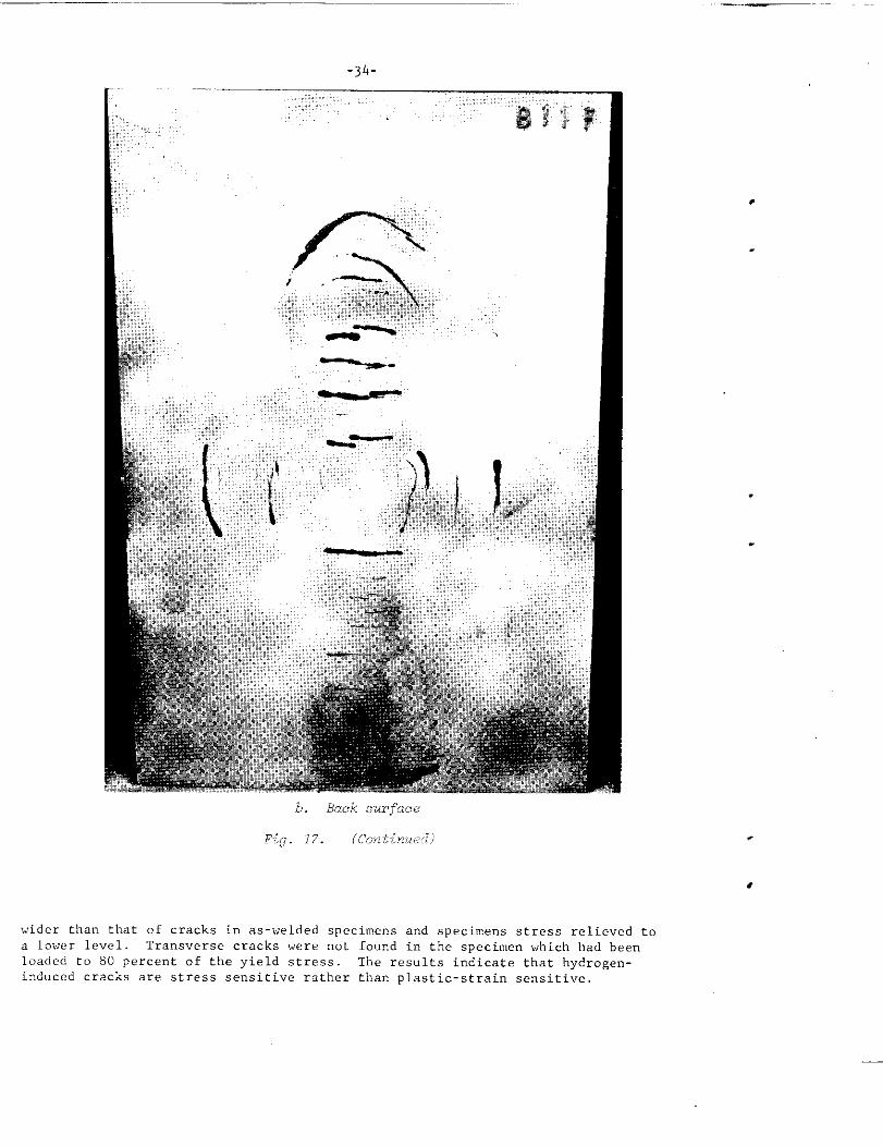
. Effect of Mechanical StreSS Relieving.Hydrogen- induced-cracking tests
were made on five bead-on-plate specimens which had been partially stress xelievedby loading up to different StSeSS levels.
Figures 19a, b, and c show hydrogen-
induced crack patterns obtained in Specimens D8, DL, and D6, respectively.
Regularly spaced transverse cracks were obtained in the as-welded specimen andthe specimens which had been loaded to 20 and 40 percent of the yield stress. In
the specimen loaded to 60 percent of the yield stress , the interval of cracks was
.. .... . . —–
m
b. Back surface
Pi<g. 17. (continue(l)
wider than that of cracks in as-welded specimens and specimens stress relieved to
a lower level. Transverse cracks were not found in the specimen which had beenloaded to 80 percmt of the yield stress. The results indicate that hydroge”-imluced cracks are stress sensitive rather than plastic-strain sensitive,
-35
Front surface
Fig. 18. Crack pattern in complex-structure specimen withserrated transverse and longitudinal plates.
Hydrogen-Induced-Cracking Tests on Press-Fit Specimens
Hydrogen-induced-cracking tests were conducted on five press-fitspecimens made in SAE 4340 steel and in the commercial high-strength structural
steel.
. Experimental Methods
Four ring specimens, 3/8 inch thick, 2-1/2 inches in inner diameter,and 10-7/8 to 11 inches in outer diameter, were made fro” SAE 4340 steel oilquenched from 1550 F and tempered at 500 F for 1 hour. A ring specimen, 3/8 inchthick, 2-1/2 inches in inner diameter, and 10 inches in outer diameter, was madein the conrnercialhigh-strength structural steel water quenched from 1650 F andtempered at 350 F for 1 hour (the “hard condition”)
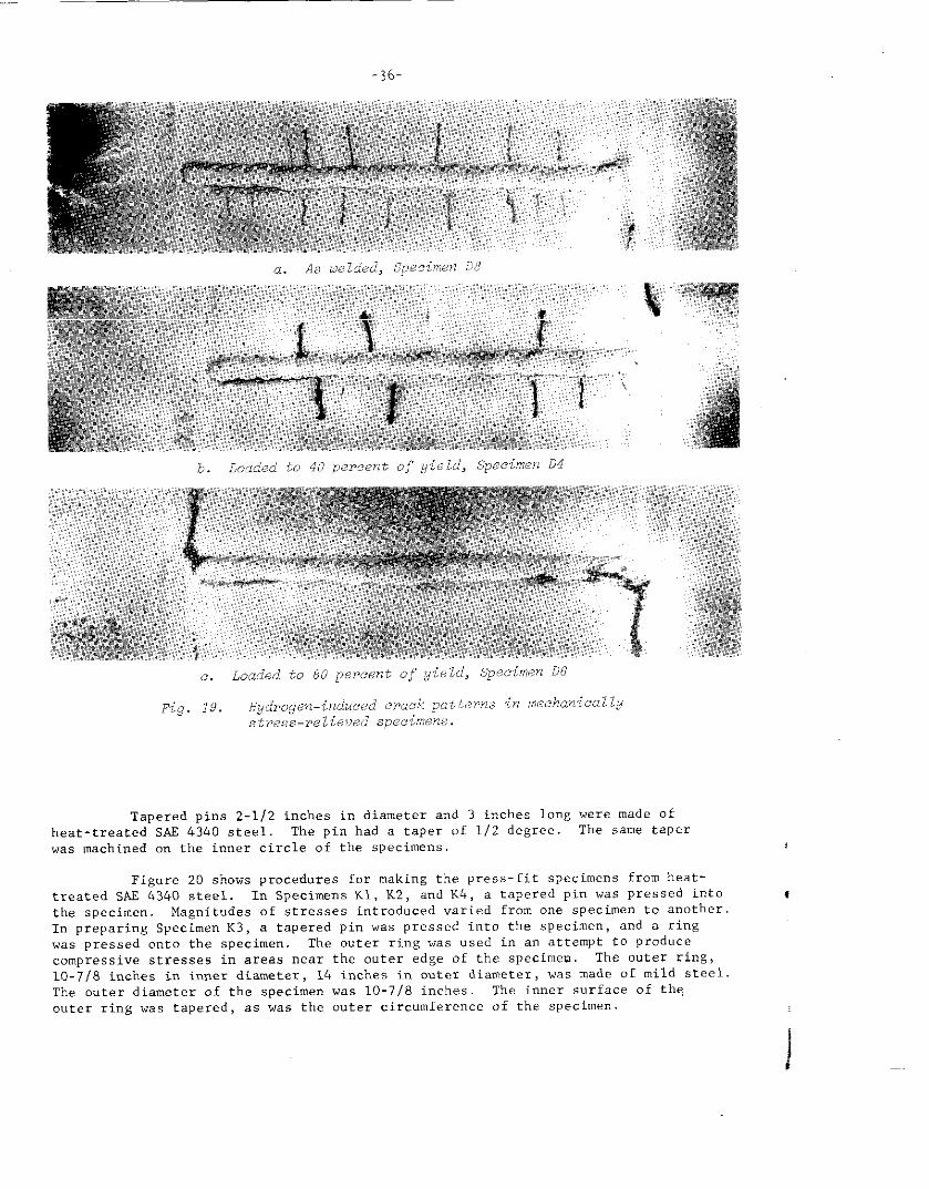
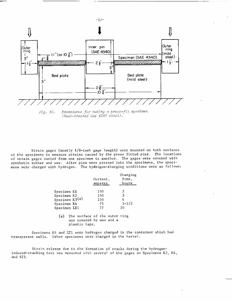
Tapered pins 2-1/2 inches in diameter and 3 inches long were made ofheat-treated SAX 4340 steel. ‘Thepin had a taper of 1/2 degree. The same taperwas machined on the inner circle of the specimens. I
Figure 20 shows procedures for making the press-fit specimens from heat-treated SAE 4340 steel. In Specimens K1, K2, and K4, a tapered pin was pressed intothe specimen. Magnitudes of stresses introduced varied from one specimen to another.I“ preparing Specimen K3, a tapered pin was pressed into the specimen, and a ringwas pressed onto the specimen. The outer ring was used in an attempt to producecompressive stresses in areas near the outer edge of the specimen. The outer ring,10-7/8 inches in inner diamete~, 14 inches in outer diameter, was made of mild steel.The outer diameter of the specimen was 10-7/8 inches. The inner surface of theouter ring was tapered, as was the outer circumference of the specimen.
-37-
1 n
IT “ ‘- -— -
Outer Inner pin @ter
ring
‘“a “:’ E ‘fiLIi I I I
/////////////////////////
Fig. 20. PPOcedurws ;“OYmaking a press-~it specimen(Heat-treated SAE 4340 steel).
Strain gages (mostly l/8-inch gage length) were mounted on both surfacesof the specimens to measure strains caused by the press fitted pins. The locations
of strain gages varied from one specimen to another. ‘i”hegages were covered with
synthetic rubber and wax. After pins were pressed into the specimens , the speci-mens were charged with hydrogen. The hydrogen-charging conditions were as follows:
ChargingCurrent, Time,amperes hours
Specimen K1 150 3Specimen K2 150 3Specimen K3(a) 150 4Specimen K4 75 5-1/2Specimen LT1 77 20
(a) The surface of the outer ringwas covered by wax and aplastic tape.
Specimens K4 and LT1 were hydrogen charged in the container which hadtransparent walls. Other specimens were charged in the barrel.
Strain release due to tbe formation of cracks d“ri,]gthe hydrogen-induced-cracking test was measured with several of the gages on Specimens K3, K4,and LT1.
-38-
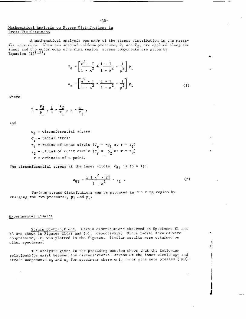
Mathwnatical Analysis on Stress Distributions inPress-Fit Specimens
A mathematical analysis was made of the stress distribution in the press-fit specimens, When two sets of uniform pressure, PI and P2, are applied along the
inner and the outer edge of a ring region, stress components are given byEquation (1)(13):
[ 1L.-!I+L.IL. L ~1
“a=1-ML l-x2p2
[
2or = 1q-q”+P1
l-x l-n. p
where
and
‘e = circumferential stress
a = radial stressr
‘1= radius of inner circle (0= = ‘PI at r = rl)
‘2= radius of outer circle (or = -pz at r = r2)
r = ordinate of a point.
(1)
The circumferential stress at the inner circle, Uol is (P = 1):
.1+ M2 -21)’91 - “PI”
(2)
1-X2
Various stress distributions can he produced in the ring region by
changing the twO pressures, PI and PZ.
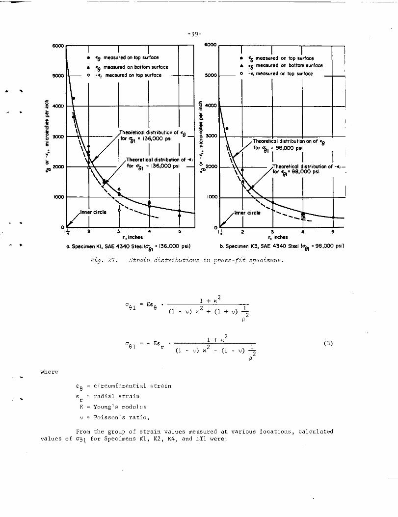
Experimental Results
Strain Distributions. Strain distributions observed on Specimens Kl and
K3 are shown in Figures 21(a) and (b), respectively. Since radial strains were
compressive, -er was plotted in the figures. Similar results were obtained on
other specimens.
The analysis given in the preceding section shows that the followingrelationships exist between the circumferential stress at the inner circle cr81andstrain components ee and Cr for specimens where only inner pins were pressed (1=0):
\.,I
I
ScOO
. . 5.!!=.-E
lm
. .
.,
where-
. .
0
Rb’”’’rmpsil’”-w’’”’”ps”ps’ ‘ ~
Tfmorehcoldistr,b~mof-c,–
N&/’nn’l’cim” T’W lhlcir;’ ‘--- -
1 \ w 1 1 I Iwo I I \ I I
1 1 1 I I I I I 12 3 4 5
or,& * 3 a s. . -
r,inches r,-irwtws
aSpecimen Kl, SAE4340Steel (me, =136JXIJ psi) b. Specimen K3, SAE4340Stee10z81 =98 S00rm0
Fig. 21. Strain distributions in press-fit specimens.
= EE8 .1+M2
‘81(1- V) M2 +(1+”)+
P
1 +X.2’01 = - Ecr “ (l-. )K* -(l-V)+
P
‘e = circumferential‘traine = radial strainrE = Young’s modulus
v = poisso*vs ratio.
(3)
From the group of strain values measured at various locations, calculatedvalues of ag~ for Specimens K1, K2, K4, and LT1 were:
-40-
c. S,pecimen.K3,Ool = 38,000 Psi,
Tet7ted for 4 hours
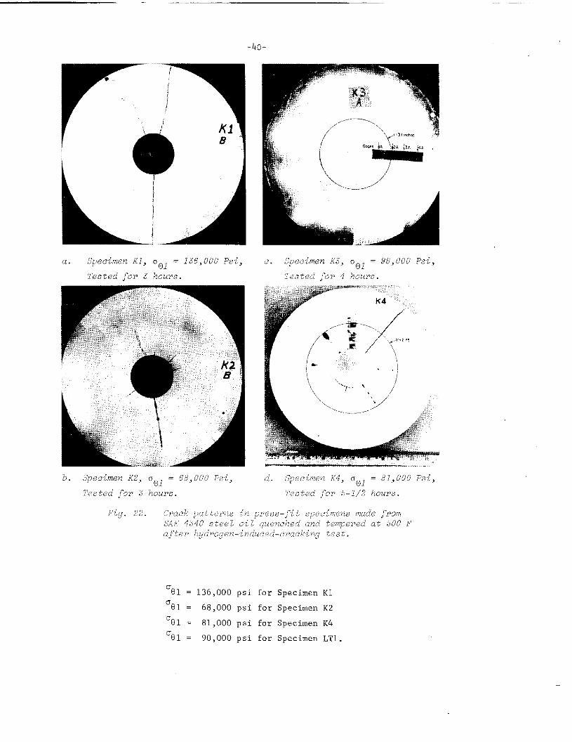
‘B1 = 136,000 psi for Specimen KI
’81 = 68,000 psi for Specimen K2
’91 = 81,000 psi for Specimen K4
‘el = 90,000 psi for Specimen LT1.
-41-
Theoretical distributions of eg and Er were then calculated using the abovevalues of UgI and were compared with measured strain values, The theoreticalstrain distributions and measured strain values coincided very well, as shown i“Figure 21a.
Strain distributions obtained cm Specimen K4 are shown in Figure 21b.At a low-stress level compressive stresses were p~aduced hy the outer ring;
. .however, the outer ring had little effect on stress distributions at highermaximum stresses. The outer ring was made with mild steel, and this maY ha”ekept it from working effe.ti”ely i“ pressing the specimen made with heat-treated
. .SAS 4340 steel, Tbe theoretical stress distributions shown in Figure 10b wereobtained assuming that T = O, The vaLue of Gel was estimated as:
‘e 1= 98,OOO psi for Specimen K3.
Results of Hydro,qen-Induced-Cracking Test Figures 22a through d showthe crack patterns obtained in SAS 4340 specimens (KI th~ongb K4) Completefracture cccurred i“ Specimen Kl, where residual stresses were high (OBl = 136,000psi). Systems of radial cracks were obtained in Specimen K2 (u~l = 68,000 psi)
and in Specimen K3 (0~~ = 98,000 psi), In Specimen K4 (081 = 81,000 psi), asimilar system of radial cracks was formed after hydrogen charging for 5-1/2hours ; howe”er , a crack extended after the hydrogen-induced-cracking test was
over and the specimen fractured completely.
., -In Specimen LT1 made from a commercial high-strength heat-treated
structural steel, several short cracks were obtained after bydi-ogen cbargi”g for
A* 13-1/2 hours. Hydrogen charging was co”ti”ued for 20 hours. After the chargingwas stopped, a crack extended and the specimen fractured completely.
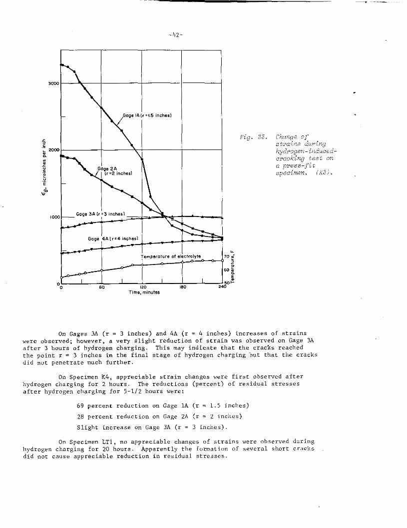
Change of Strains During Hydro.en-Induced- Cracking Test. Figure 23shows tbe change of strains d“rin$ hydrogen-induced-cracking test observed onfour gages mounted o“ Specimen K3’<. The locations of the gages are shown inFigure 22c,
On Gage 1A located close to the pin (r = 1.5 inches), the strain begs”
to decrease after several minutes of hydrogen charging. The strain decreasedsteadily for about 3 hours, after which m appreciable further decrease wasobserved. The strain decreased from 3270 microi”ches per inch at tbe initialstage to 668 micro inches per inch after 4 hcmrs of charging (zed”ctio” of strain:80 percent)
On Gage 2A (r = 2 inches) , a pronounced reduction of strain was observedafter hydrogenthe whole test
,.
.-
charging for about 25 minutes, The strain decreased steadily forperiod. The rcd”ction of strain for 4 hours was 64 percent.
~:The temperat”rc of the electrolyte increa~ed 12 F during hydrogen charging. Thecorrection for tiletemperature change of the measured values has bee” made
_ ..–._
30<
10,
-42-
Goge IA{r:l.5inches)
Gage 4Alr=4 inches)
Tempw.wce .f electrolyte
I I I I60 120 180
Time, 1111.uP.s
Fig. 23. Change ofstrains duringhgdrogen-induced-cracking teet on
a Ppfss ‘Joitspec%m~n. (X3).
On Gages 3A (r = 3 inches) and 4A (r = 4 inches) increases of strainswere observed; however, a very slight reduction of strain was observed on Gage 3Aafter 3 hours of hydrogen charging. This may indicate that the cracks reached
the point r = 3 inches in the final stage of hydrogen charging but that the cracksdid not penetrate much further.
On Specimen K4, appreciable strain changes were first observed afterhydrogen charging for 2 hours. The reductions (percent) of residual stressesafter hydrogen charging for 5-1/2 hours were:
69 percent reduction on Gage 1A (r = 1.5 inches)
28 percent reduction on Gage 2A (r = 2 inches)
Slight increase on Gage 3A (r = 3 inches)
On Specimen LT1, no appreciable changes of strains were ohserved duringhydrogen charging for 20 hours. Apparently the formation of several short cracksdid “ot cause appreciable reduction in residual stresses.
-43-
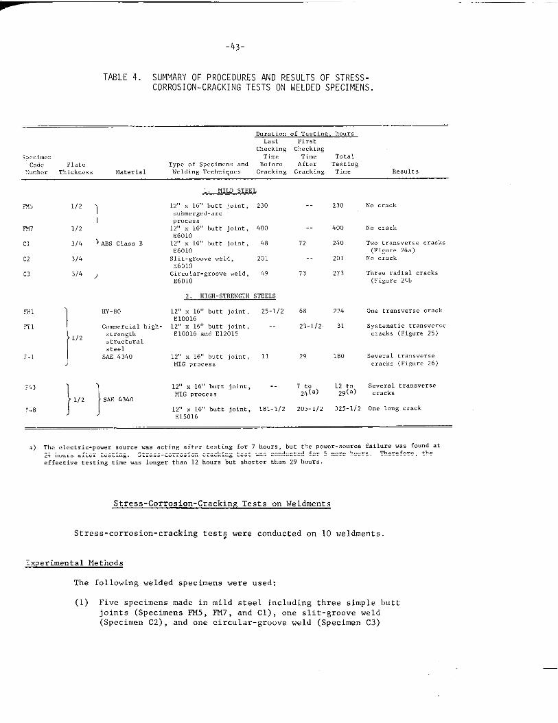
TABLE 4. SUMMARY OF PROCEDURES AND RESULTS OF STRESS-CORROSION-CRACKING TESTS ON WELDED SPECIMENS.
Duration of Te.ti”E, hoursLast First
Checking Checkings,eci.en Time Tie TotalCode Plate TYP. of specie.. ..d Bef..e After Testi”~
xumber Thick”... Material Welding l’echnique. Cracking Cracking Time Results
IX7 1/2
c1 31L
C2 314
:3 3/4
liw80
C.mnerci.1 high-Screngtt!structuralsteel
SAE 4340
1, MILD STEEL
12C’x 16,,butt joint , 230s.bmerged-arc
process12,’x 16,,butt joint, 600E601O
12,, x 16S, butt jol”t , 48E601OSlit-groove weld, 201E601OCircular-groove weld, 49E601O
2. HIGK-STRINGTH STEELS
12,,x 16,>butt joint, 25-1/2E1OO1612,,x 16’,butt joint, --E1OO16 and E12015
12>,x 16” butt joint , 11MIG Process
12<,x 16,,butt joint , -MIG Process
12,, x 161, butt joint, 181-1/2
E15016
230
-. 400
72 240
.. 201
73 273
68 224
23-112 31
29 180
No crack
No crack
‘ho tra.”sversecrack.(Figure 24.)
NO crack
Three radial cr.cks(Fignre Z&b
0“. tra”sve,se crack
systematic transversecracks (Figure 25)
severaltransversecracks (FiL!ure26)
7 to 12 to several transverse24(.) 29(a) crack,
205-1/2 325-1/2 One I.”’acrack
a) The electric-power sour.. was acting after cesti”g for 7 hours , but the p.wer-s.urce failure V.S f..”d at24 hours after testing. Stress-.orrosi.”-cracking test was conducted for 5 more hours. Therefore, theeffective testing time ..s 10”ger than 12 hours but shorter than 29 hours
Stress-Corrosion-Cracking Tests on Weldments
Stress-corrosion-cracking test$ were conducted on 10 weldments.
experimental Methods
The following welded specimens were used:
(1) Five specimens made in mild steel including three simple buttjoints (Specimens FM5, FM7, and Cl) , one slit-groove weld(Specimen C2) , and one circular-groove weld (Specimen c3)
—
-44-
216
{I68144
0273
A
’93 973
7 73
193 9797
273193273
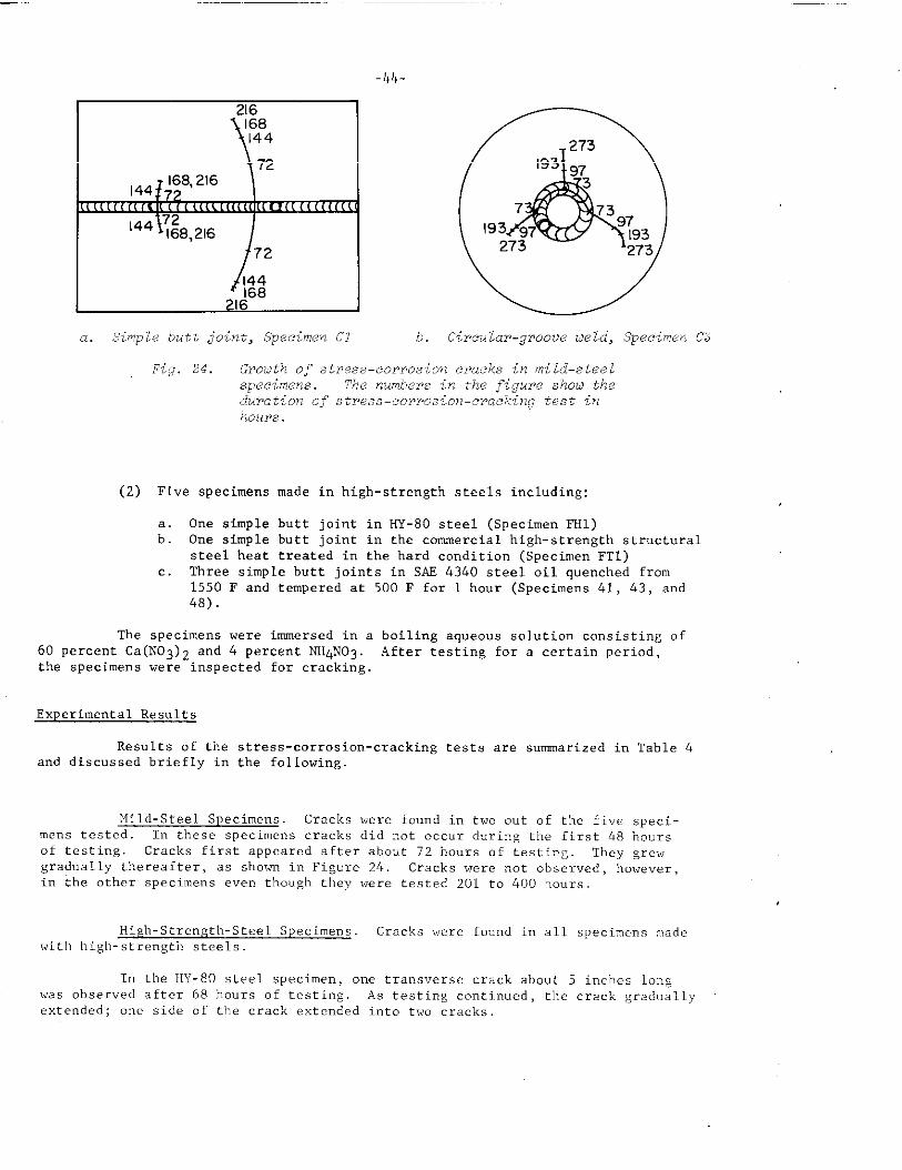
a. b’implebutt joint, Specimen Cl b. Cireular-groove w ld, Specimen C3
Fig. 24. Grouth of stress-corrosion cracks in mild–steelspecimens. l%e numbers in the figure shotitheduration of stre.ss-corr,ot:ion-cracking test inhours
(2) Five specimens made in high-strength steels including:
;:
c.
One simple butt joint in HY-80 steel (Specimen FHl)One simple butt joint in the commercial high-strength structuralsteel heat treated in the hard condition (Specimen FT1)Three simple butt joints in SAF 4340 steel oil auenched from1550 F and tempere~ at 500 F for 1 hour (Specim~ns 41, 43, and48).
The specimens were immersed i“ a60 percent Ca(N03)2 a“d 4 percent NH4N03.the specimens were inspected for cracking,
Experimental Results
Results of theand discussed briefly in
boiling aqueous solution consisting ofAfter testing for a certain period,
stress-corrosion-cracking tests are sumarized in Table 4the following
Mild-Steel Specimens, Cracks were found in two out of the five speci-mens tested, In these specimens cracks did not occur during the first 48 hours
of testing, Cracks first appeared after about 72 hours of testing. They grewgradually thereafter, as shown in Figure 24, Cracks were not observed, howewr,i“ the other specimems even though they were tested 201 to 400 hours.
Higl, -Stre”gtl,-Steel Specimens. Cracks ~were found in all specimens made
with high-strength steels
I“ tbe HY-80 steel specimen, one trans”ersc crack about 5 inches longwas obser”ed after 68 hours of testing. As te.stingcontinued , the crack graduallyextended; on. side of the crack extended into two cracks.
45-
,.
. .
.
“.
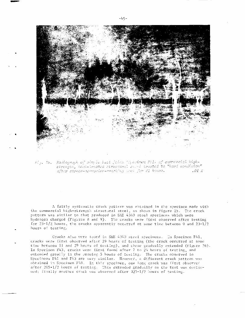
A fairly systematic crack pattern was obtained in tl,cspecin,enmade withthe .OmmeICial lhigh-str.ngth structural steel , as sl,o,.m in Fi&ure 25 The crack
pattern was similar to that prOCILICCd in S,lE4340 steel speciTnenswhich werehydrogen charged (Figures 8 and Y) lle cracks were Cirst observed after testingCor 23-1/2 11OU.S, tl,ecrack. al>l]arentlyoccurred at some time between O and 23-112hours 01 testing,
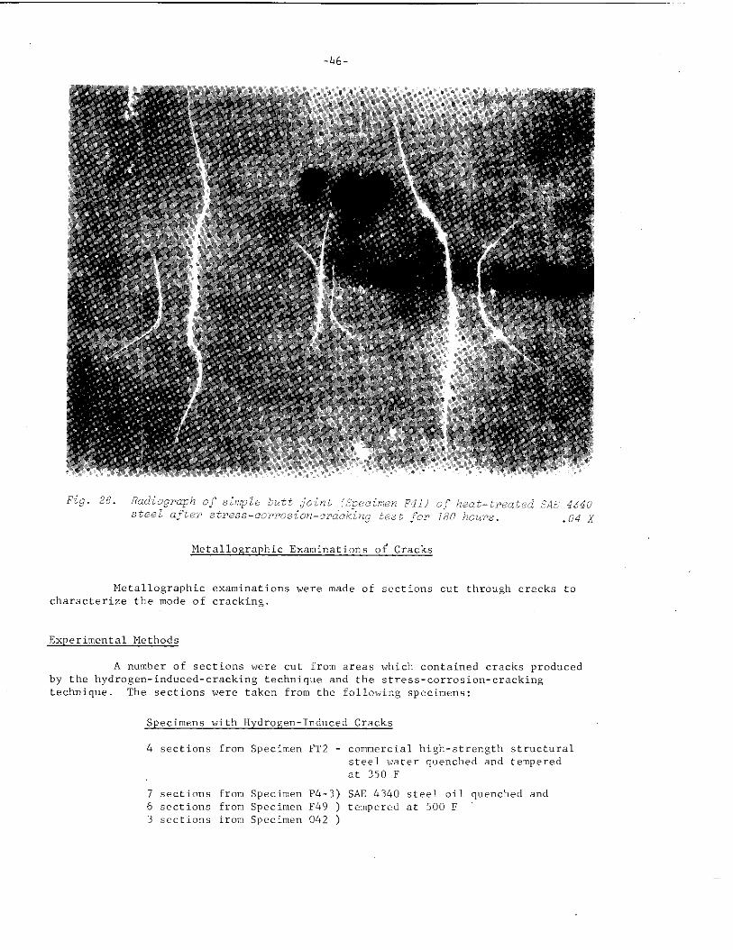
-46-
Metal lographic Examinations of Cracks
Metallographic examinations were made of scct?ons cut tbrougkl cracks to
characterize the mode of cracking.
Experimental Methods
A number of sections were cut from areas which contained cracks produced
by the hydrogen-induced-cracking technique and the stress-corrosion-crackingtechnique. The sections were taken from the following specimens:
Specimens with Hydrogen-Induced Cracks
4 sections from Specimen FT2 - commercial high-strength structuralsteel water quenched and temperedat 350 F
7 sections from Specimen P4-3) SAE 4340 steel oil quenched and6 s?ctio”s from Specimen F49 ) tempcrcclat 500 F3 sections from Spccime” 042 )
-47-
Specimens with Stress-Corrosion Cracks
6 sections from Specimen FT1 - commercial high-strength structuralsteel water quenched and temperedat 350 F,
6 sections from Specimen F43 - SAE 4340 steel oil quenched a“d. tempered at 500 F.
Figure 8b shows locations of Sections 042-1, 042-2, and 042-3 take” from. Specimen 042. All sections were cut in such a way that the tips of the cracks
could be examined. Metal lographic exami”atio”s were made o“ the center plane(middle of the plate thickness) of the sections.
Experimental Results
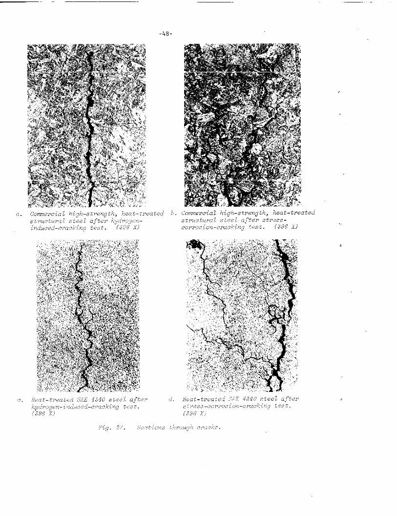
Figures 27a, b, c, and d are photomicrographs of cracks. On the speci-mens made i“ the commercial high-strength structural steel, different modes offracture were found between hydrogen-induced cracks and stress-corrosion cracksHydrogen-induced cracks were transgrs.nular, while stress-corrosion cracks wereintergranular, as shown in Figures 27a and b, respectively, On the SAS 4340steel specimens , both hydrogtm-induced cracks and stress-corrosion cracks wereintergranular, as shown i“ Figures 27c a“d d,
. Measurements of Residual Stresses byStress-Relaxation Techniques
,,
Measurements of residual stresses by stress-relaxation tech”iq”es usingstrain gages were made on 8 weldments in mild steel .md SAS 434o steel.
Experimental Methods
Specimens The following welded specimens.were prepared:
(1) Three mild-steel specimens -
Specimen OM1, butt joint, 1/2 by 12 by 16 inches
Specimen Till,butt joint , 5/8 by 24-1/4 by 38 inches
Specimen 3CM, complex welded structure
.
. .
(2) Five specimens made from SAE 4340 steel oil q“e”ched from 1550 Fand tempered at 500 F
Specimen Rl, butt joint, 1/2 by 12 by 16 inches
Specimen S1, butt joint , 3/4 by 12 by 16 inches
Specimen S2, butt joint, 3/4 by 18 by 32 inches
Specimen T41, butt joint, 5/8 by 24-L12 by 38 inches
Specimen 3C41, complex welded structure.
-48-
cormerciaz high-strength, heat-treated~~ru’.f,uraz.5tee~.~“,”terstress-
C0FP0Si071-CWUCkiYZg teSt. (396 X)
.49.
. II
~
II cut2c“’ ‘W 1’
~Weld Center—— —.
Line—
i+iII1+1
~1+1 #cut 3
v
Y—-—— ——— -——
[ i- –-.;+; - – –-–*IIIIIIIIi+l
X11i+i
19“ —
w 38” I
a. Large-size butt joint
i– l“-f
Single Direction Goge
&8’’ -~”~” ‘~! ~“
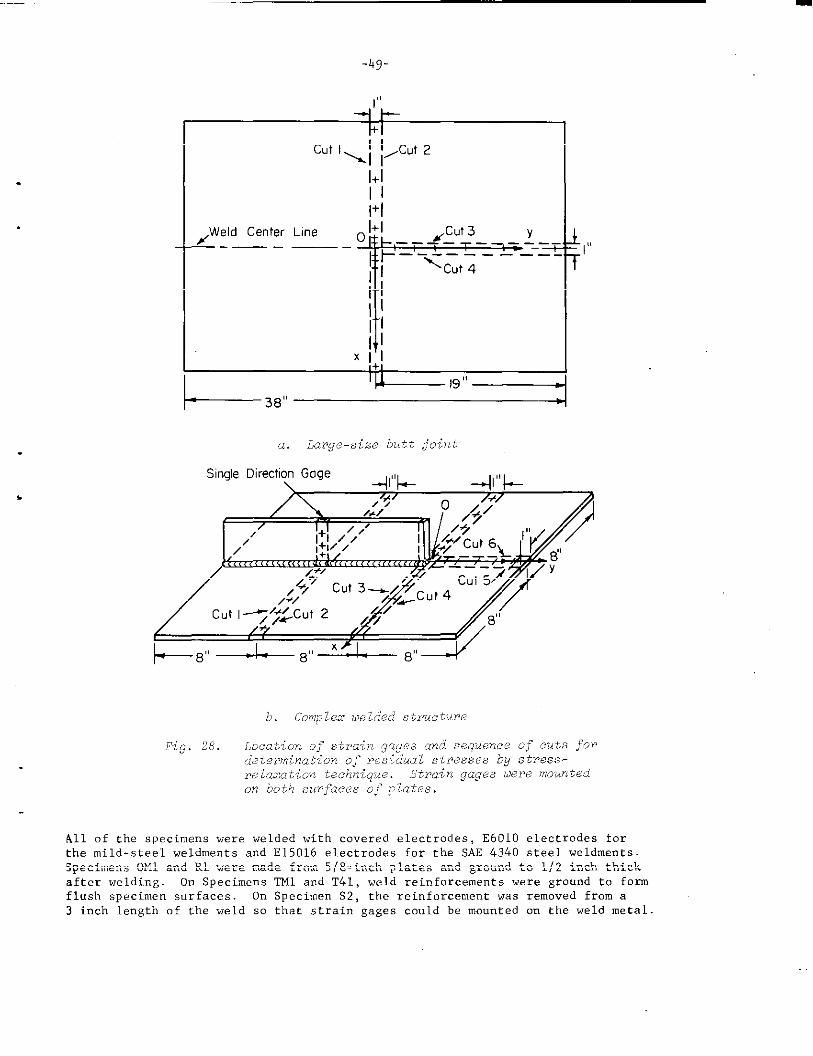
All of the specimens were welded with covered electrodes, E601O electrodes forthe mild-steel weldments and E15016 electrodes for the sAE 4340 steel weldments.Specimens OM1 and RL were made from 5/8-inch plates and ground to 1/2 inch thickafter welding. On Specimens TM1 and T41, weld reinforcements were ground to formflush specimen surfaces. On Specimen S2, the reinforcement was removed from a3 inch length of the weld so that strain gages could be mounted on the weld metal
_ . - -—-—
-50-
,Surface plate
// : ,~
Specimen4X/
=.=== ===== -=>y–––+Y
HeightL< -–-.’__ .-––2/. J
gage
Stand(height~ adjustable)
/
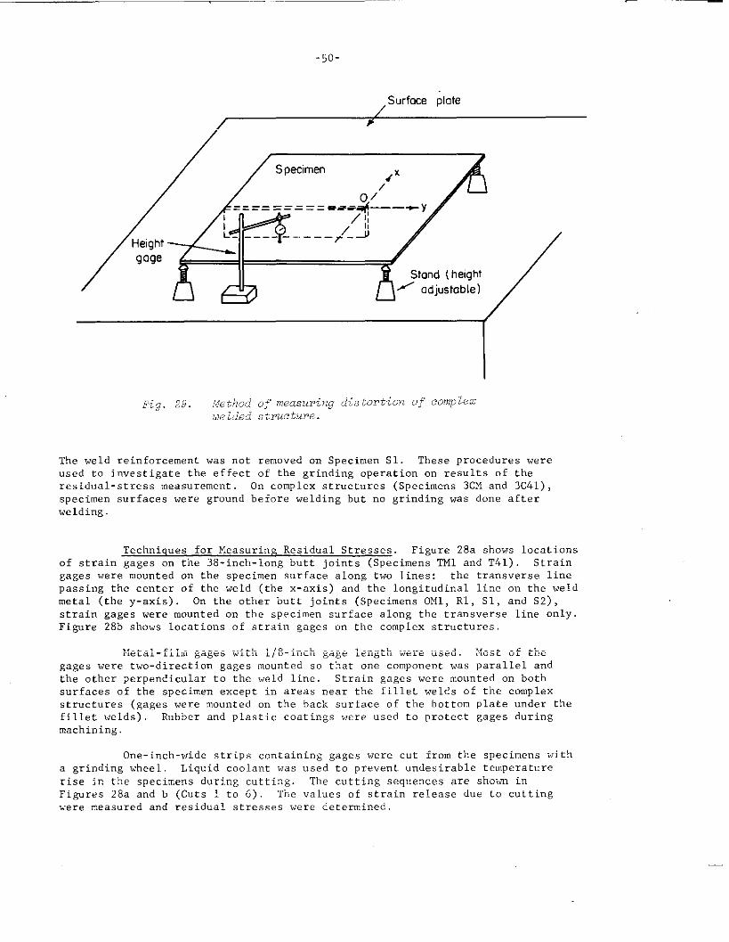
Fig. 29. ?,jethod~j’measuring di,stcu+hl Of COW kZ
uelded structure.
The weld reinforcement was not removed on Specimen S1. These procedures wereused to investigate the effect of the grinding operation on results of theresidual-stress measurement On complex structures (Specimens 3CM and 3c41) ,specimen surfaces were ground before welding but no grinding was done afterwelding.
Techniques for Measuring Residual Stresses. Figure 28a shows locationsof strain gages on the 38-inch-long butt joints (Specimens ml and T41) Straingages were mounted on the specimen surface along two lines: the transverse linepassing the center of the weld (the x-axis) and the longitudinal line cm the weldmetal (the y-axis) On the other butt joints (Specimens OM1, Rl, S1, and S2) ,strain gages were mounted on the specimen surface along the tra”svsrse line only.Figure 28b shows locations of strain gages on the complex structures.
Metal-film gages with l/8-inch gage length were used. Most of thegages were two-direction gages mounted so that one compom-”t was parallel andthe other perpendicular to the weld line. Strain gages were mounted on bothsurfaces of the specimen except in areas near the fillet welds of the complexstructures (gages were mounted on the back surface of the bottom plate under thefillet welds), Rubber and plastic coatings were used to protect gages duringmachining,
One-inch-wide strips cmtaining gages were c“t from the specimens witha grinding wheel Liquid coolant was used to prevent undesirable temperaturerise in the specimens during cutting. The cutting sequences are shown inFigures 28a and b (Cuts 1 to 6). The “alues of strain release d“e to cuttingvere measured and residual stresses were determined,
-51-
.
. .
4.
L
80 — T
‘m—
()\B
‘1
L 1$: c s *–++* –+—60 — r’
,— ~z ‘m“o—.%
40 — Ii; ~lz+ 12; +
=. Front surface, right
z.- A Fmnl surface, left:‘x A O Back surfoce, right= 20 — A Back surface, leftc.—.~.-?~
0 . A g I $ I Iu
R
A :*
-20 I I I I I Ia 2 4 6 8 10 12
OistanceFrom Weld Center Line, inch
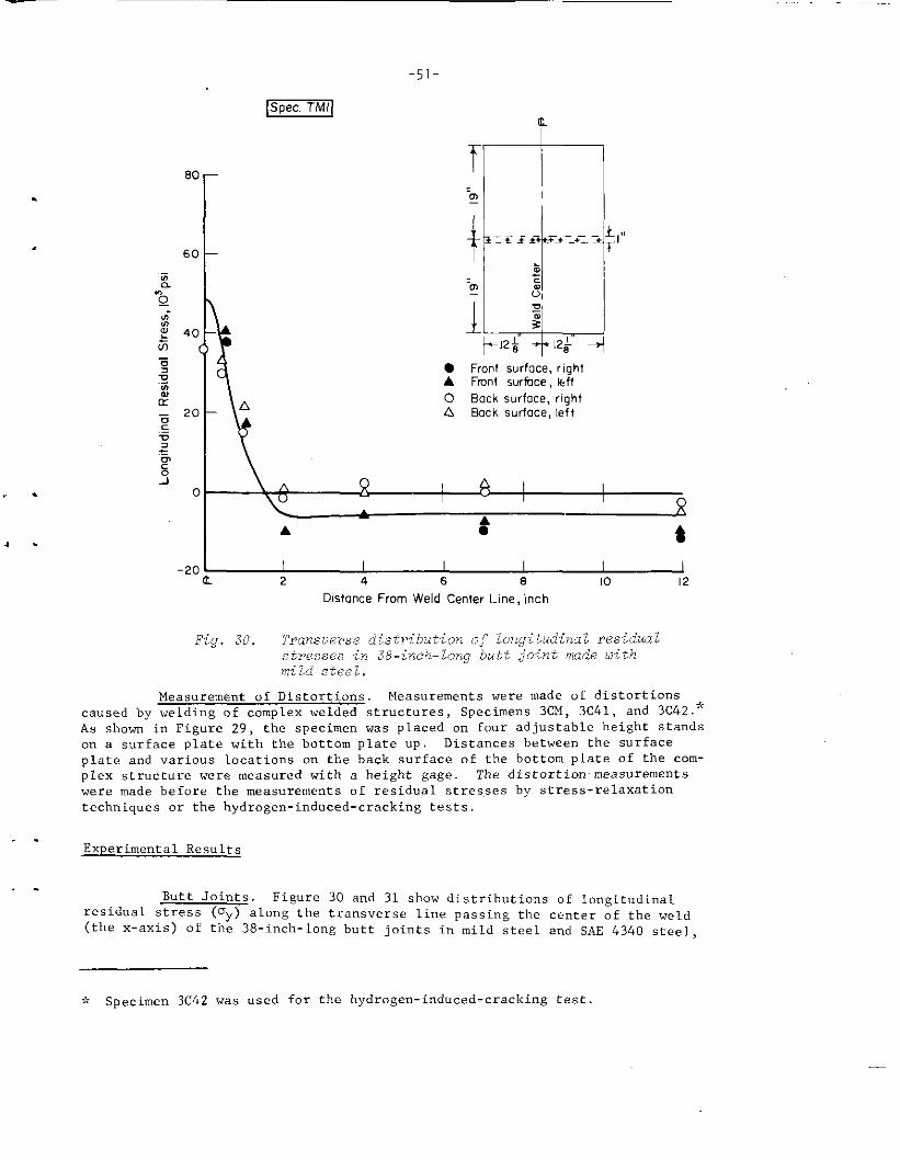
Fig. 30. Transverse distribution of lorwitudinal residualstresses in 38-incklong butt ~oint made oithmild steel.
Measurement of Distortions. Measurements were made of distortionscaused by welding of complex welded structures, Specimens 3CM, 3C41, and 3C42.
*
As shown in Figure 29, the specimen was placed on four adjustable height standson a surface plate with the bottom plate up Distances between the surfaceplate and various locations on the back surface of the bottom plate of the com-plex structure were measured with a height gage. The distortion measurementswere made before the measurements of residual stres,sesby stress-relaxationtechniques or the hydrogen-induced-cracking tests.
. .Experimental Results
. .BtittJoints Figure 30 and 31 show distributions of Iongitudi”al
residual st=es.s (aY) along the transverse line passing the center of the weld(the x-axis) of the 38-inch-long butt joints in mild steel and SAE 4340 steel,
,V Specimen 3c42 was used for the hydrogen-induced-cracking test
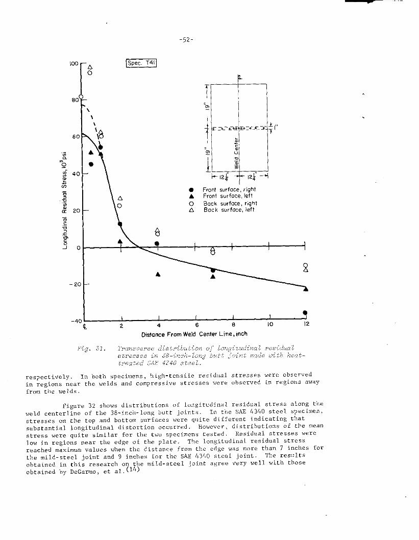
.
● Front surfoce, lightA Front surface, left
o Bock surfoce, rightA Bock surface, left
6
+ ● I ! 1
A A
I I 1 I I ?2 4 6 8 10 12
Distance From Weld Center Line, inch
big. 31. Transverse distr?;but’ionof Long,itu&naZ re.sidwlGtresses -;r’38—inG~}[-Z(7}ICJh tt ,;Oirit ,msdeLlith.heat–treatea’SAE 4.340 steel.
respectively In both specimens, high-tensile residual stresses were observed
in regions near the welds and compressive stresses were observed in regions awayfrom the weld,
Figure 32 shows distributions of longitudinal residual stress along theweld centerline of the B8-inch-10ng butt joints. In the SAE 4340 steel specimen,
stresses on the top and bottom surfaces were quite different indicating thatsubstantial longitudinal distortion occurred. however, distributions of the mean
stress ve~e quite similar for the two specimens tested. Residual stresses were
10V in regions near the edge of the plate. ‘The longitudinal residual stress
reached maximum values when the distance from the edge was more than 7 inches forthe mild-steel joint and 9 inches for the S.4E4340 steel joint. The results
obtained in this research on the mild-steel joint agree very well with thoseobtained by DeGanno, et al.(14)
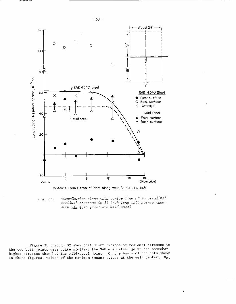
-53-
~About 24”+
[
~_________
Io
0
00 ‘E ~
1c1....... .
I 1+,
o1+11+,1,1
‘~ ,+,Ill
1
,+11,1II
-{+
r SAE 4340 steelr
.;-&q\Mild steel \
\\
SAE 4340 Steel
● Front su rfoceO Bock surfaceX Average
Mi Id Steel
A Front surfaceA Back surface
I I I I I4 8 12 16 19
Centev (Plme edge)
Oistonce From Center of Plate Along weld Center Line, inch
F%g, 32. Distribution along wld center line of long~tu~~nalresidual stres~o.sin 3&inch -10ng butt joints made
with SAE 434o steel and mila steel.
Figure 30 through 32 show that distributions of residual stresses inthe two butt joints were quite similar; the S.42434o steel joint had somewhathigher stresses than had the mild-steel joint. On the basis of the data showin these figures, values of the maximum (mean) stress at the weld center, Do 3
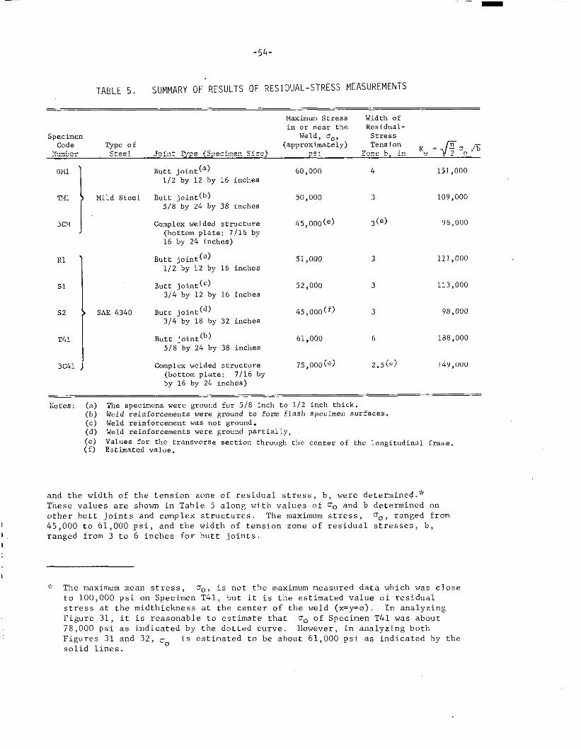
-54-
TABLE 5. SUMMARY OF RESULTS OF RESIDUAL-STRESS MEASUREMENTS
Maximum Stress Width ofin or near the I/esidual -
specimen Weld, Oo>
Codestress
~e; fNumber
(aeerox~ately) TensionJoint ‘rYPe (SpecimenSize) psi K =fi OoJ%
Zone b, in w
OM1
ml IMild Steel
3CM
RI
51
S2
1
SAE 4340
T&l
3C41
Butt joint(a) 60,000 4 151,000
1/2 by 12 by 16 inches
Butt joint(b) 50,000 3 109,000
5/8 by 24 by 38 inches
complexwelded structure 45,000(e) 3(,) 98,000(bottomplate:7116 by16 by 24 inches)
Suet joint(a) 51,000 3 111,000112 by 12 by 16 inches
Butt joint(c) 52>000 3 113,000314 by 12 by 16 inches
Bucc joint(d) 45,000~f) 3 98,0003/4 by 18 by 32 inches
Butt joint(b) 61,000 6 188,000518 by 24 by 38 inches
Compl.X welded structure 75,000(e) 2.5(e) 149,000
(bottom plate: 7116 by
by 16 by 24 inches)
Notes: (a) The specimenswere groundfor 518 inch to 1/2 inch thick.(b) Weld reinforcements were ground to font flash specimensurfaces.(c) Weld reinforcementwas not ground.(d) Weld reinforcementswere sroundpartially.
(e) Vale. for the transversesectionthroushthe centerof tbe longitudinalframe,(f) Estimatedvalue.
and the width of the tension zone of residual stress , b, were determined .9<These values are shown in Table 5 along with values of DO and b determined onother butt joints and complex structures. The maximum stress, ‘JO,ranged from
1 45,OOO to 61,000 psi, and the width of tension zone of residual stresses, b,I ranged from 3 to 6 inches for butt joints.
1
>,: The maximum mean stress , Oo, is not the maximum measured data which was closeto 100,000 psi on Specimen T41, but it is the estimated value of residualstress at the midthickness at the center of the weld (x=Y=o) In analyzingFigure 31, it is reasonable to estimate that 00 of Specimen T41 was about78,000 psi as indicated by the dotted curve. However, in analyzing bothFigures 31 and 32, ~. is estimated to be about 61,000 psi as indicated by tbesolid lines.
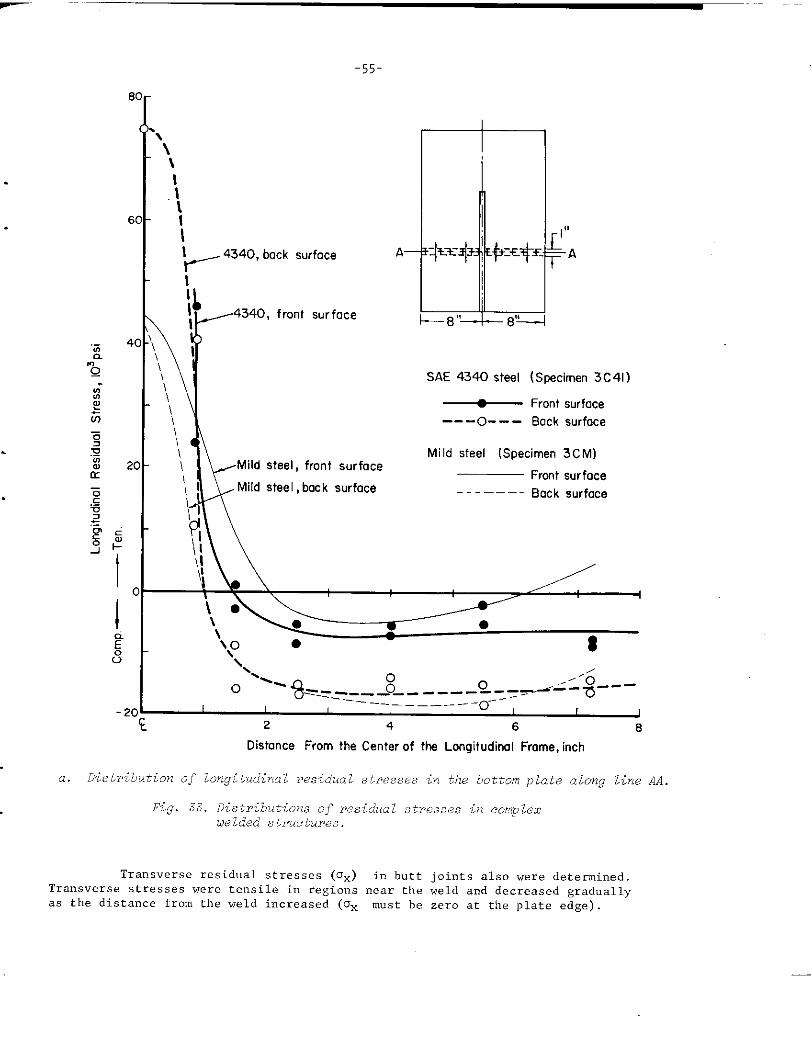
_.
-55-
8
6
4
2
‘\\\
.\(II
‘~ 4340, bock surface
iI 4340, front surfoceI
\r
‘\ I\\\
[
A ++ ++.
k13° 8‘L
SAE 4340 steel (Stxximen 3C41)
i\.!
~ Front surface
\ --- --- Bock surfaceo\
\\‘IIF Mi Id steel [Specimen 3CM)
Mild steel, front surfoceFrcmt surface
,1 Mild stee 1, bac k surface---–––– Back surface
,1
‘\
o ““ %-z?s-_-_-$-----=_..+-%----20 1
?- 2 4 6 8
Distance From the Center of the Longitudinal Frame, inch
a. Distribution of longitudinal residual stres,sesin the bottom plate along line AA
Fig. 3,3.Di6tributi.on6 of residual stresse,sin complez
uelded structures.
Transverse residual stresses (ox) in butt joints also were determined.Transverse stresses were tensile in regions near the weld and decreased graduallyas the distance from the weld increased (Ox must be zero at the plate edge)
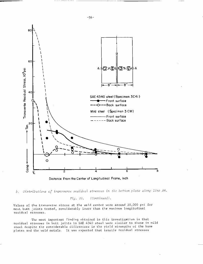
-56-
\\\\ m\\\
II
IIIIIIi SAE 4340 steel ( Specimen 3C41 )
~ Front surface
\
-- -c--- Back surface
II Mild steel (Specimen 3 CM)
\ — Front surface
●\------ Back surface
\
\II
IIII
I\‘ . . .
\ o\ -.~~\ ~, /’0
o
Distance From the Center of Longitudinal Frame, inch
h, Distributions o~-trarwuersf? -late alwng line AA.residuczlstresses ir. the bottcm ~
w~~., ;f:f (Continued)
Values of the transverse stress at the weld center were around 20,000 psi formost butt joints tested, considerably lower than the maximum longitudinalresidual stresses.
The most in,portant finding obtained in this investigation is thatresidual stresses in butt joints in SE 434o steel were similar to those in mildsteel despite the considerable differences in the yield strengths of the baseplates and the weld metals. It was expected that tensile residual stresses
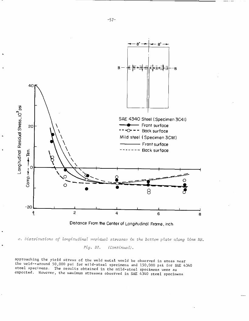
-57-
4C
.—!4“o—.
-20
B—
SAE 4340 Steel (Specimen 3C41)
~ Front surface
---c--- Back surface
Mild steel (Specimen 3CM)
— Front surface
\‘ ------ Back surface
Y, J
\i
\o _-— —
0● ●
8 8
1 1 ! 1 I 1 1
‘1 2J
4 6 8
OistanceFrom theCenterafLongitudinalFrame, inch
c. Distributions of longitudinal residual stres.se,sin the bottom plate along line BB.
Fig. .33. (Continued).
approaching the yield stress of the weld metal would be observed in areas nearthe weld--around 50,000 psi for mild-steel specimens a“d 150,000 psi for SAE &3f+0steel specimens, The results obtaimsd in the mild. steel specimens ~e=e ~~expected. Hovevei-, the maximum stresses obser”ed in SU 4340 Steel specimens
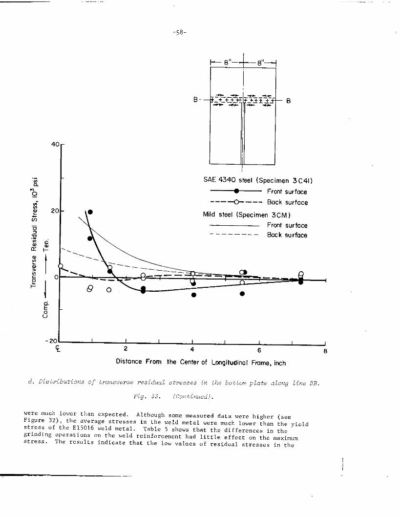
t
4(
2(
mk 8“ 8“1
SAE 4340 steel(Specimen 3C41)
~ Frontsurface
----C---- Back surface
Mildsteel (Specimen 3CM )
Fro-tsurface–-––—––– 8ock surface
I I I I I I 12
I4 6 8
DistanceFrom the Centerof LongitudinalFmme, inch
d. Distributions of transverse residual stresses in the bottom plate along line BB.
Fig. 33. (Continued).
were much lower than expected. Although some measured data were higher (seeFigure 32), the average stresses in the weld metal were much lower than the yieldstress of the E15016 weld metal. Table 5 shows that the differences i“ thegrinding operations on the weld reinforcement had little effect o“ the maximumstress. The results indicate that the low “alues of residual stresses in the
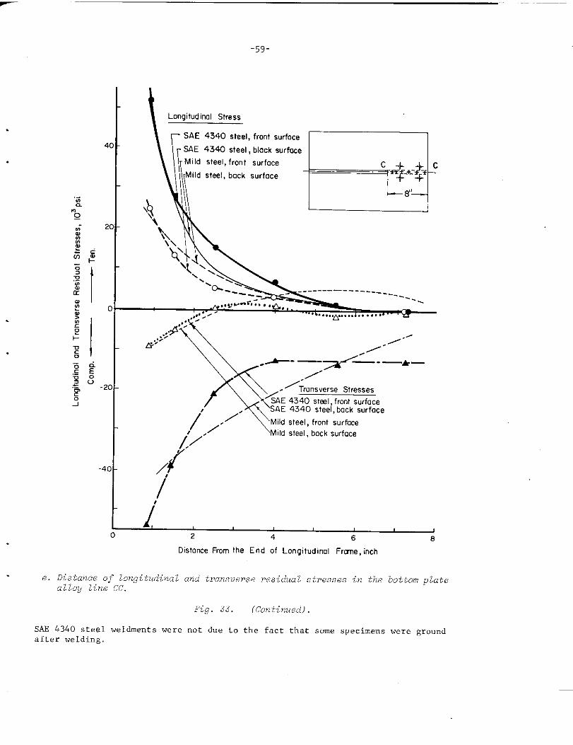
.
-59-
— SAE 4340 steel, front surface
- SAE 4340 steel, black surface
Mild steel, front surface
Mild steel, back surface
‘k,
\\\\ Q
‘ .G
&-” ./”O//
—- —A——
Transverse Stresses
SAE 4340 steel, front surfaceSAE 4340 steel, back surface
/’,,”Mild steel, frontSUrfaCe
J,’/
Mildsteel, back surface
,
L2
I4 6 8
Oistance From the End of Longitudima Frame, i“~h
e. Di6tance of longitudinal and transverse residual stresses in the bottom platealloy line CC.
Fig. 33. (Continued).
SAE 4340 steel weldments were not due to the fact that some specimens were groundafter welding,
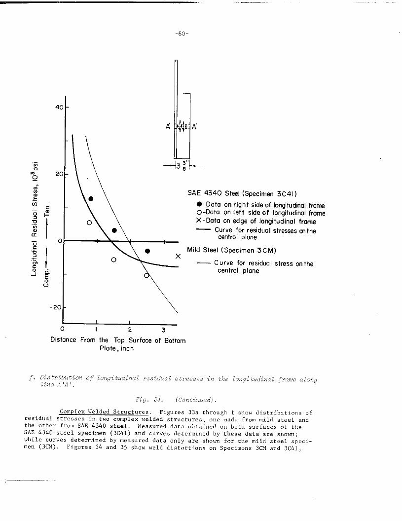
-6o
-2C
o
0
\
SAE 4340 Steel(Specimen3C41 )
● -Data on rightsideaf Iongitudinolframeo -Data on Ieft sideof IongitudinolframeX- Data on edge of Iangitudinalframe— Curve far residual stresses cnthe
central plane
Mild Steel (Specimen 3CM)
— Curve for residual stress on thecentral plone
Distance From the Tap Surface of Bottom
Plate,inch
Fig. 33. (Continwxi.1
Complex Welded Structures. Figures 33a through f show distributions ofresidual stresses in two complex welded structures, one made from mild steel andthe other from SAE 434o steel, Measured data obtained cm both surfaces of theSAE 4340 steel specimen (3C41) and curves determined by these data are shown;while cu=ves determined by measured data only are shown for the mild steel speci-men (3CM) Figures 34 and 35 show weld distortions on Specimens 3CM and 3C41,
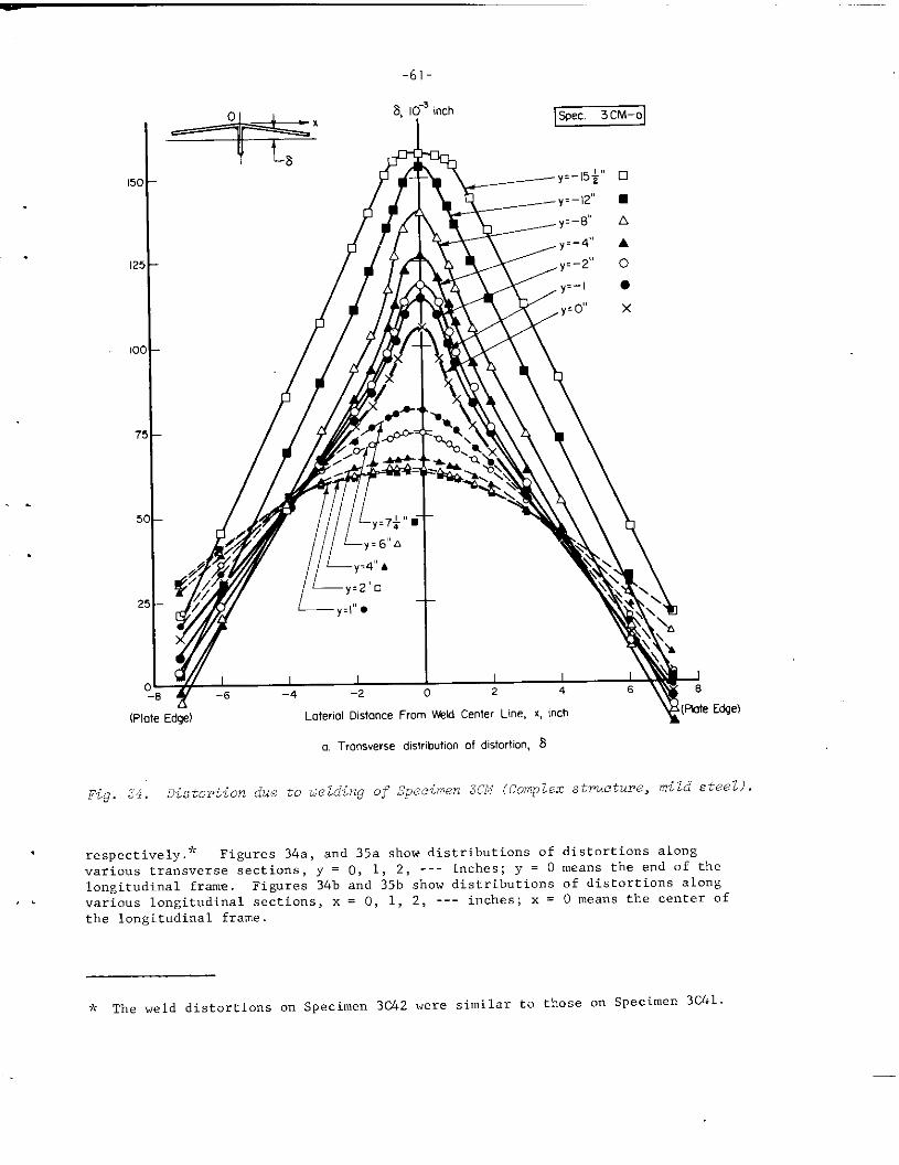
-61-
(Plate Edz} Loteriol Oistonce From Web Center Line, x, inch ~(.klle Edge)
a. Transverse tis!r[ bution of distortion, 8
Fig. 34. i)istortion due to tielding or”Specimen 3CM (complex structure, mild steel) .
respectively.y< Figures 34a, and 35a show distributions of distortions along
various transverse sections, y = O, 1, 2, --- inches; y = O means the end of the
longitudinal frame. Figures 34b and 35b show distributions of distortions alongvarious longitudinal sections, x = O, 1, 2, --- inches; x = O means the center of
tbe longitudinal frame.
* Tbe weld distortions on Specimen 3c42 were similar to those on Specimen 3C41.
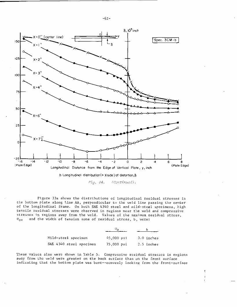
-62-
.“
I\x=6,, 4
’25-16 -14 -12 -10 ‘8 ‘6 -4 -2 0 2 4 6 8
(PIOreEdge)Longitudinal Distance from the Edge of Vertical Plote, y, inch
(Plate Edge]
b. Longitudi!ml distribution (+ Xside ) of distmtion, E
Fig. 34. (Continued).
Figure 33a shows the distributions of longitudinal residual stresses inthe bottom plate along Line AA, perpendicular to the weld line passing the centerof the longitudinal frame. On both S.4F434o steel a“d mild-steel specimens, hightensile residual stresses were observed in regions mar the weld a“d compressivestresses in regions away from the weld, Values of the maximum residual stress,
To9 and the width of tension zcme of residual stress, b, were:
00 b
Mild-steel specimen 45,000 psi 3.0 inches
SAE 4340 steel specimen 75,000 psi 2.5 inches
These values also were shown in Table 5. Compressive residual stresses i“ regionsaway from the weld were greater on the back surface than on the front s“rfa.cei“dicati”g that the bottom plate was bent--convexly looking from the front-surface
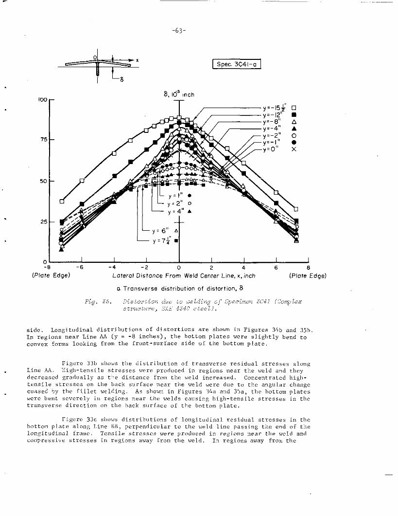
-63-
100
75
50
25
Spec. 3C41-a
8,103 inch
T— ~=.154 ❑
k’ I-8 -6 -4 -2 0 2 4 6 8
(Plate Edge) Lateral Distance From Weld Center Line, x, inch (Plate Edge)
o. Transverse distribution of distortion, 8
Fig. 35. ,?istortion due to oelding of Specimen 3C41 (Complex~.zrtic~fzre,SW 4340 steel).
side. Longitudinal distributions of distortions are shown in Figures 34b and 35b.In regions near Line AA (Y = -8 inches), the bOttom plates were slightly bend toconvex forms looking from the front-surface side of the bottom plate.
Figure 33b show?,the distribution of transverse residual stresses a.longLine AA. High-tensile stresses were produced in regions near the weld a“d theydecreased gradually as the distance from the weld increased, Concentrated high-tensile stresses on the back surface near tbe weld were due to the angular cb.angecussed by the fillet welding. As shown i“ Figures 34. and 35a, the bottom plateswere bent severely i“ regions near the welds causing high-tensile stresses in thetransverse direction a“ the back surface of the bottom plate,
Figure 33c shows distributions of lo”git”dinal residual stresses in thebottom plate along Line BB, perpendicular to the weld line passing the end of thelongitudinal frame. Tensile stresses were produced in regions near the weld andcompressive stresses in regions away from the weld. In regions away from the
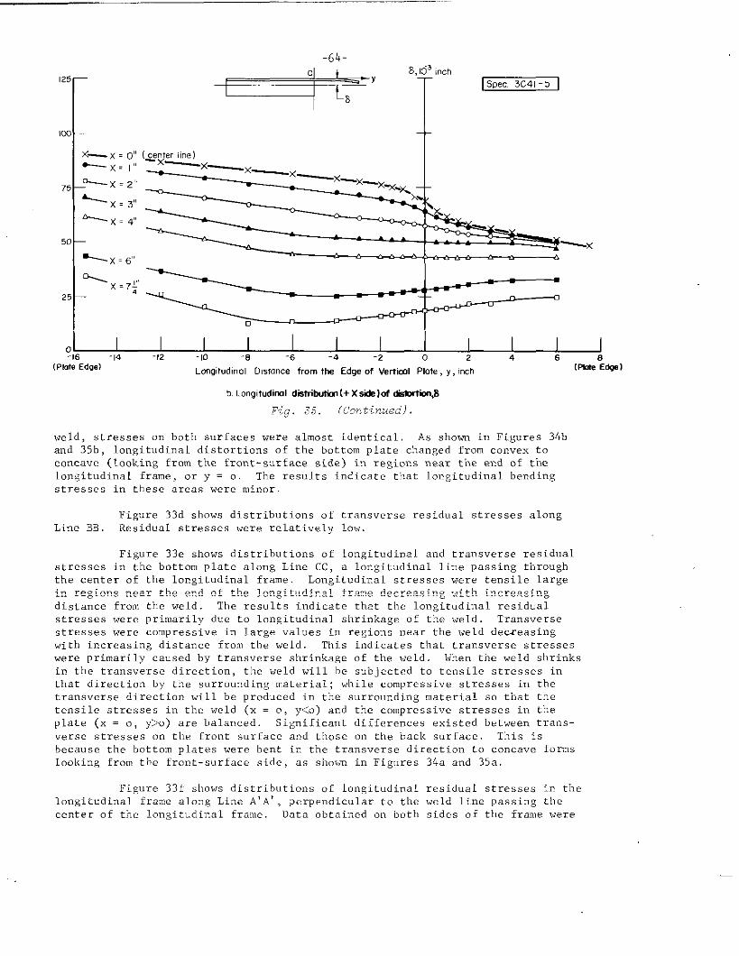
12:
IW
7?
5[
2:
c
(PI.
x— x ,~“ (center1,”, )D--x= ,4! - x—~_
.+.-x=~’,
-----X=3(8
:-:
-
inch
spe..3c41-b I
‘*.X
-
dwl LongitudinalDism.cefromtheEdgeofVertiullPlate,Y,inch (FIG&l
b.Longit.dinoldistrilwtim (+ X skle)of ~8
Fig. 35. (Continued).
weld> stresses on both surfaces were almost identical. As shown in Figures 34b
and 35b, longitudinal distortions of the bottom plate changed from convex toconcave (Looking from the front-surface side) in regions near the end of thelongitudinal frame, or y = o. The results indicate that longitudinal bendingstresses in these areas were minor.
Figure 33d shows distributions of transverse residual stresses alongLine BB. Residual stresses were relatively low,
Figure 33e shows distributions of longitudinal and transverse residualstresses in the bottom plate along Line CC, a longitudinal line passing throughthe center of tbe longitudinal frame. Lcmgit”dinal stresses were tensile large
in regions near tbe end of the longitudinal frame decreasing with increasingdistance from the weld. The results indicate that the lo”git”dinal residual
stresses were primarily due to longitudinal shrinkage of the weld. Transverse
stresses were compressive in large values in regions near the weld deceasingwith increasing distance from tbe weld. This indicates that transverse stresses
were primarily caused by transverse shrinkage of the weld. When the weld shrinksin the transverse direction, the weld will he subjected to tensile stresses inthat direction by the surrounding material; while compressive stresses in thetransverse direction will be produced in the surrounding material so that thetensile stresses in the weld (x = o, y<o) and the compressive stresses in theplate (x = o, Y>O) are balanced. Significant differences existed between trans-
verse stresses on the front surface and those on the back surface. This is
because the bottom plates were bent i“ the tranwerse direction to conca”e formslooking fro” the front-surface side, as shown in Figures 34a and 35a,
Figure 331 shows distributions of longitudinal residual stresses in thelongitudinal frame along Line A’A’ , pcrpendic”lar to the weld line passing the
center of the longitudinal frame. Data obtained on both sides of the frame were
sormwbat different indicating that the longitudinal frame was slightly bent inthe lateral direction. High-tensile stresses were produced in regions near theweld and compressive stresses in regions near the top edge of the frame.Figures 34b and 35b show that the bottom plate under the frame x = o was bentlongitudinally in a concave form looking from the Front surface indicating that
considerably high compressive stresses could be produced in regions near the top. edge of the frame.
Figures 33 through 35 show that distributions of residual stresses and. .
distortions were quite similar in distribution in complex structures made in mildsteel and SAE 4340 steel. Little difference was found between the magnitude ofresidual stresses in the two weldments. The magnitude of the distortions in the
mild-steel specimen were considerably higher than those in the SAE 4340 specimensThis is probably because the mild-steel specimen was welded without preheating,while the S.4E4340 steel specimens were welded with 400 F preheat a“d interpa,sstemperature.
-66-
ANALYTICAL INVESTIGATIONS
Objectives
In the experimental hydrogen-induced-cracking tests on weldedand press-fit specimens it was found that:
(1) Crack patterns were affected by properties of thematerial,
(2) Crack patterns were affected by the magnitude anddistribution of residual stresses.
Investigations were made to establish analytical relationships among theresidual-stress distribution, properties of the material, and the crackpattern. Attempts also were made to apply findings obtained in theanalytical investigations to the interpretation of experimental results.
General Theory of the Crack PatternProduced by Residual Stresses
Background
The Griffith theory has been widely used as a fundamental state-ment of the mechanism of fracture in a brittle material and has bee”
applied by many investigators to various types of brittle fracture. (15-17)The modified Griffith theory developed by Irwin a“d others is often calledfra.ture mechanics theory, and it is widely applied to the fractures ofhigh-strength steels and nonferrous materials. (18-20)
In the Griffith-Irwin fracture mechanics theory, the stabilityof a crack i“ a solid is discussed. If a straight crack of length 1 = 2aoccurs in an infinite plate (of uniform thickness) subjected to uniformtensile stress, 0, the elastic strain energy stored in the plate decreasesbut additional energy is required to produce the new surfaces. Therefore,
the decrease in the total energy in the plate (per unit thickness) , U, is
expressed as follows:
U= W,- W,=J+ - Zpl (4)
where
we = decrease in elastic strain energyMS = energy required to produce the new surfaceP = ~Ount Of energy required to produce a surface
of unit a~ea.k
E = Young’s modulus.
.:.In case of a metal, the “alue of p is mostly plastic work, as has been
pointed out by Felbeck and Orc!wan.(21)
}
I
-67
The crack is unstable
when (1) the stress oof J!and p or (2) theas follows :
. .
ifiy>oai “
In other
exceeds the criticalcrack length exceeds
words , the crack will propagate
stress, acr (for given values
the critical crack length, Acr,
“’”CA%
,4>1 ❑~
Cr(5)
TTU2
In fracture mechanics theory, the critical stress-i”te”sity
factOr, Kc, and the critical crack-extension force. G.. are widelv usedfor chara~terizing the material property sometimes ”ca~ied fracture tough-ness , as
,.
,. Unstablecritical
follows :
K’GC= 2P=+ (6)
fracture occurs when the stt-ess-intensity factor, K, exceeds thestress-intensity factor Kc of the material, as follows:
KZfia.O>Kc (7)
General ‘rheoryof Crack Pattern
An attempt has been made to develop a general crack patterntheory produced in a solid containing residual stresses by modifying theGriffith-Irwin fracture mechanics theory. However, there is a basic
difference between subjects discussed in this crack pattern theory andordinary fracture-mechanics theory. In the crack pattern theory, themajor concern is to determine the crack pattern that is stable. Infracture mechanics theory, on the other hand, the major concern is todetermine the condition for the occurrence of unstable fracture.
. . Another important problem in the crack pattern theory is that it isessential to assume that residual stresses are not uniformly distributedin the solid. TIIecrack may be curved, a“d there may be more than onecrack.
When a crack occurs in a solid containing residual stresses,new surfaces appear and the residual stresses that existed in regionsnear the crack are partially released. If the decrease in residualstress strain energy due to the strain release is greater than the energyrequired to produce the new surfaces, a crack will form since the totalenergy of the solid decreases due to the occurrence of the crack.
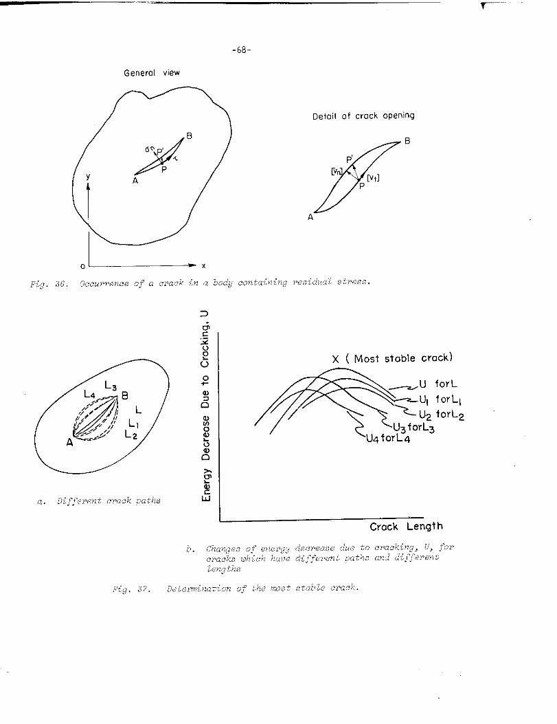
-68-
Generol view
Deioilof crock Opening
.L__-xFig. .36. Occurrence of a crack in a body containing residlualstress.
%
a. Different crack paths 5
x ( Most stobie crock)
ICrock Length
-69-
The increase of surface energy depends on the properties of thematerial and is considered to be proportional to the surface area of thecrack. when a crack of length A (between A and B in Figure 36) occurs ina plate of uniform thickness, the increase of surface energy per unitplate thickness, W~, is given by:
w~ = 2p!.
r= 2P d,A
(8)
P = amount Of energy required to produce a surface ofunit area
ds = -. line elemen~.
‘Themajor characteristics of the changes of residual stressesthat take place during the formation of the crack are:
(1)
(2)
Since residual stresses are released due to cracking,the stress changes are considered to be elastic evenwhen the pre-existed residual stresses are caused byplastic deforrnation>~
As the crack surface will remain free from stress aftercracking, the normal and shearing stresses that were
acting along the crack will be fully released.
Consequently, the decrease in elastic-strain energy of residual stresses
per unit thickness due to tbe occurrence of tbe crack, We, can be deter-
mined from knowing (1) tbe residual stresses that were acting along the
crack before cracking and (2) the relative displacement of botb sides of
the crack or tbe crack opening, as follows ~:?::
We. ~ ,,2 {On[Vn, + W+]}d.A
(9)
>,< E“en when a material is in the plastic state, the strain change during“nloa,dingis elastic.
M In many applications , the relative displacement along the crack, [ut],is considerably smaller than that in the normal direction, [vnl. Ins“c1lcases tbe second term in Equation (9) can he neglected.
-70-
where
On, T = normal and shearing residual stresses, respectively,that were acting along the crack
[vn], [vt] = relative displacements of both sides of the crack
in the normal and tangential directions,respectively.
The decrease in the total energy of the system, U, is:
u=we-w~ (lo)
Since the stress changes due to cracking are considered to be elastic,the relationships between the residual stress along the crack, (On, T) ,and the crack opening, ([vn], [vt]), can be determined anal tically as aproblem of the theory of elasticity. Xasubuchi and Martin(52) ha”e co”.
ducted an analysis of stress changes due to the formation of a crack.Consequently, the decrease in total energy, U, can be calculated when thepath of the crack and the residual stresses that were acting along thecrack are known.
The stability of a crack is now considered. First of all, thevalue of U must be positive if a crack is to form. However, there may bemany different crack paths between two points , A and B, as shown by
Ll, L2, ‘... in Figure 37(a) , which may satisfy the above condition.Different values of energy decrease UI, UZ, ...... will be produced bythese different crack paths. One crack path may result in a larger “alueof U than another crack path does. The crack path that produces thelargest decrease in total energy is likely to be the preferred path be-tween A and B. The crack also will extend as long as U is increased by
(~1 ). me crack will stop when ~ = o.the increase in crack length —u B O
The above mentioned conditions are shown schematically in Figure 37(b)Relationships between the length of crack and energy decrease, U, areshown for different crack paths. The crack path (including crack length)which correspond to Point X is more stable than other paths.
The discussion so far has been about a crack between A and B.The analysis can be extended to a group of cracks. The crack pattern
that produces the maximum value of U is the one that is most likely tooccur .
The above analysis shows that the unique solution for crackpattern can be obtained by calculating the maximun value of an integralof a function determined by residual stresses and properties of thematerial. The analysis, unfortunately, shows that the reverse processis mathematically indeterminate. The unique solution of residual-stressdistribution cannot be determined from the knowledge of crack patternbecause of indeterminate coefficients associated with the integration ofunknown functions. Nevertheless it is apparent that the knowledge ofcrack pattern provides valuable information on the residual-stress dis-tribution. A comparison of c~ack patterns obtained in specimens made
with different designs and different welding procedures will providequalitative information on how the design and procedure variables affect
~-””-””””-
-71-
the residual-stress distribution. Analytical investigations are sometimesquite useful for properly interpreting the crack pattern. Further analyseshave been made of the following simple crack patterns:
(1) Transverse cracks which appeared in most of the weldsin the experimental work
(2) Circular and radial cracks in radially synnnetricstressfields.
Analyses for Transverse Cracks in Welds
Introduction
It was found in the experimental investigations that typicalhydrogen-induced cracks are short transverse cracks adjacent to the weld.This type of crack, which occurs in almost every hydrogen charged weld,
is a result of the longitudinal tensile residual stresses that are alwayspresent in the vicinity of a weld. Tra”s”erse cracks are most predominant
in simple-butt joints, as shown in Figures 8 and 9.
Results of experimental hydrogen-induced-cracking tests of welds.
made in various steels have shown that properties of the material havedefinite effects on the crack pattern, as shown in Figures 6 through 9.
When the material was embrittled badly by hydrogen charging, extensivecracks were formed . If the material was embrittled less, the cracks be-came less predominant or cracks became shorter and more widely spaced.when the material was tougher than some limit, no cracks were producedduring or after hydrogen charging.
The typical transverse cracks observed in most weldments con-sisted of short parallel cracks of about equal length spaced at aboutequal intervals. The results indicate that the distribution of longi-tudinal residual stresses has the following characteristics:
(1) High tensile stresses exist in narrow regions onboth sides of the weld
(2) The distribution of residual stresses along the weldis uniform except in regions near the end of the weld.
These characteristics have been proved in the measurements of residualstresses as shown in Figures 31 and 32.
On tbe basis of the experimental finding, analyses have beenmade for cracks in an infinite plate caused by the residual stresses asshown by “Curve AA in Figure 38(a) . It is assumed that residual stressesin the y-direction cfyo= f(x) vary along the x-direction but are unifO~in the y-direction. TWO types of transverse cards were analyzed:
(1) A straight single crack, as shown in Figure 38(b)
(2) Parallel cracks with equal length and equal spacing,as shown in Figure 38(c) .
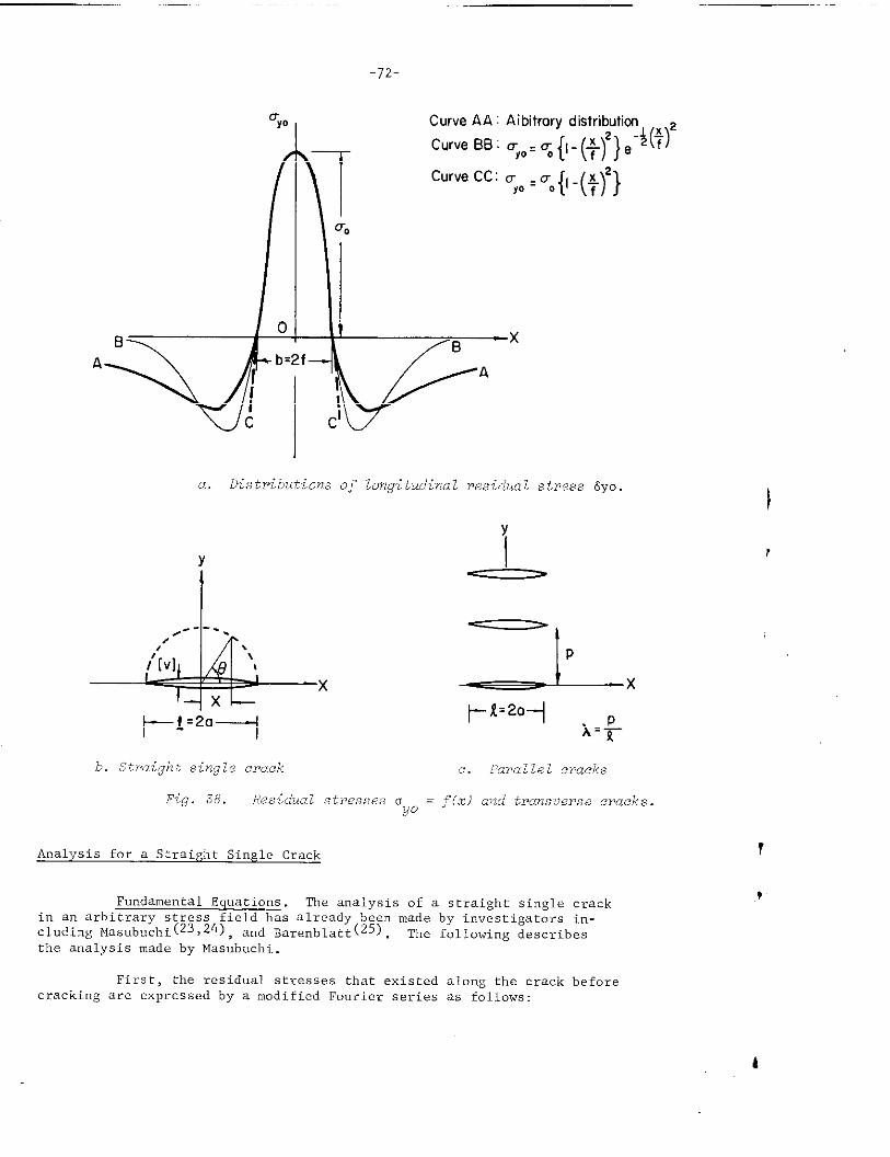
-72-
—.—
qo
I
07Co
0B
1 x
A b=2fA
J
a. Distributions of lcnqitua’inalresidual stress 6yo
Y
I
*X
CurveAA: Aibitrarydistributicnl~ ~
,{ (f)}e ‘(~)CurveBE: UYO,U 1. AZ
curvecc: % ‘u.{’-(:)’}
Y
b. .Straightsingle crock c. Parallel cracks
Fig. 38. Residual stresses o = f(x) and transWrse cracks.yo
Analysis fo~ a Straight Single Crack
Fundamental Equations . The analysis of a straight single crackin an arbitrary stress field has already been made by investigators in-cluding Masubuchi(23 ,24), and Barenblatt(25) . The following describesthe analysis made by Masubuchi.
I
r
First, the residual stresses that existed along the crack beforecracking are expressed by a modified Fourier series as follows:
.—
0 = f(x) =yo
where
E = Young’ s modulusd = 2a = crack length
-----
m
sir.:.;E ~ .Bn -Z“=1
9 = parameter which expresses the position x, COS 0 = ~.
n Jn‘yo‘in “ - ‘in e“B“ = coefficient = # . L (11-1)o
For a given stress distribution, Oyo, and crack length, A, a series Ofcoefficients BI, B2, B3, ----- can be determined by conducting the inte-grations gi”en in Equation (11-1) from 9 = O (x = a) to 0 = n (x = -a).
The oDenint?of the crack in the v-direction, [vl. also can be.=expressed in a Fourier series as follows:
,.m
[v] = X An sin ne*=1
Equation (12) satisfies the condition that the crack mustboth ends of the crack; i.e., [v]= Oatx=*aOr 9=0to Masubuchi’s analysis, the two sets of coefficients areof a straight single crack: (24),:
(12)
be closed atand n. Accordingidentical in case
An = %.
Then the strain energy released by the occurrence of the singleCrack, We, is:
.>~ The following relation exists between UYO and [vI:
.
ayo and [v] gi”en in Equations (11) and (12) satisfy the above re-lation when An = Bn.
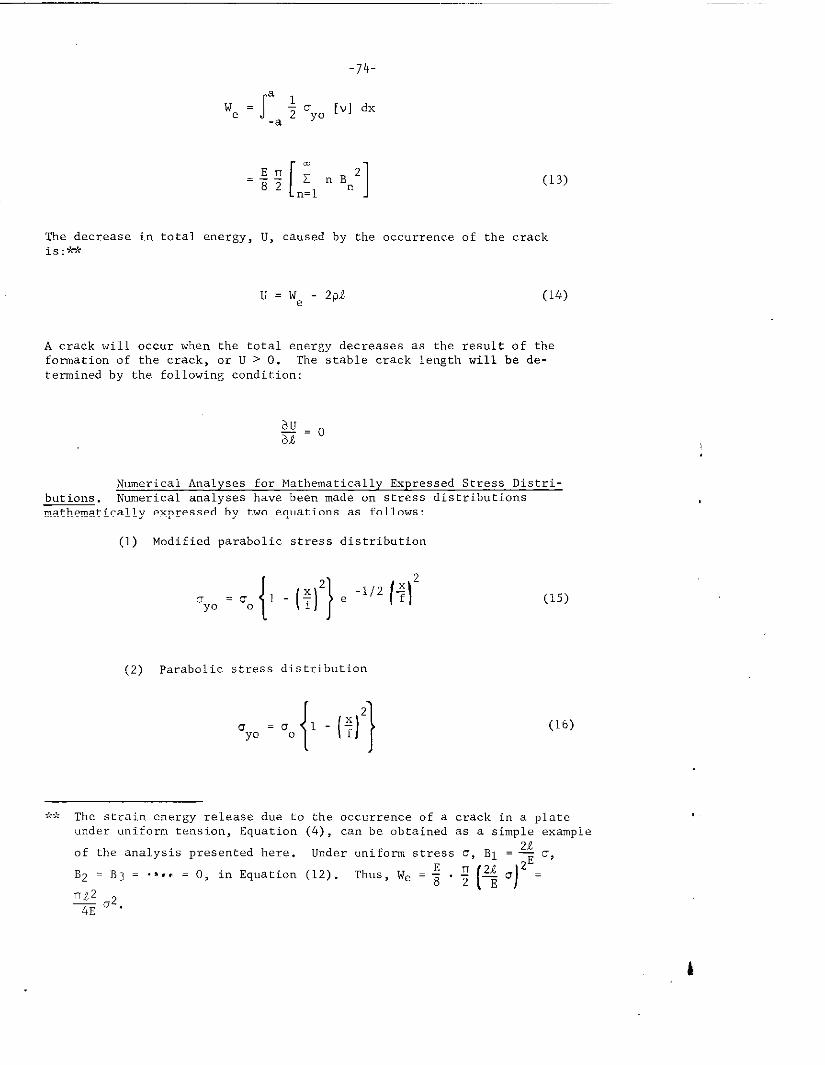
-74-
IJe = J:a + Oyo ,“, dx
(13)
The decrease in total energy, U, caused by the occurrence of the cracki~:*>t
U=we-zpk (14)
A crack will occur when the total energy decreases as the result of theformation of the crack, or U > 0. The stable crack length will be de-termined by the following condition:
Numerical Analyses for Mathematically Expressed Stress Distri-butions. Numerical analyses have been made on stress distributionsmathematically expressed by two equations as follows:
(1) Modified parabolic stress distribution
(2) Parabolic stress distribution
u = 00Yo
{1‘ - (32
(15)
(16)
,~’:The strain energy release due to the occurrence of a crack in a plateunder uniform tension, Equation
of the analysis presented here.
B2 .B~= .s.. = O, in Equation
(4) , can be obtained as a simple example
b
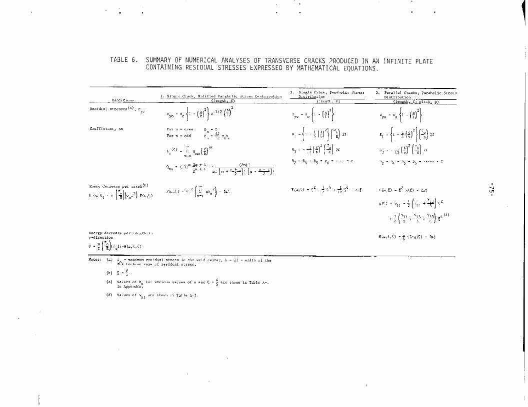
. . . . . .
TPBLE 6. SUMMARY OF NUMERICAL ANALYSES OF TRANSVERSE CRACKS PRODUCEO IN AN INFINITE PLATECONTAINING RESIDUAL STRESSES EXPRESSED BY MATHEMATICAL EQUATIONS.
C.effict.”t,B. ,0. “ = c.e” ,“ . 0
,., n - .,, ‘““% “o’. ‘ -{’-+[f)’}1:)2’ ++ff][w,“(.). ; ~m (;)’” ‘3--+[:)2(%]2’ ,3. + [{)’ (!?),,
..0,2 =,4=,5=,,= . ...=.
~ . ~.l)m~ ( 2.) !,2 = ,4 = 15 .,, =...... c
m ““+’ “’(”+*)’{”-*)’
(b) 5=;.
(.) V.,.?.., h,’ ,0, ..,,... ..,..s., . a“, $ . ; .,, #hom in ,=!,,, . . .
in AP,..d,x.
(d) V=l”es of , art showr in T,,,, .-3..,
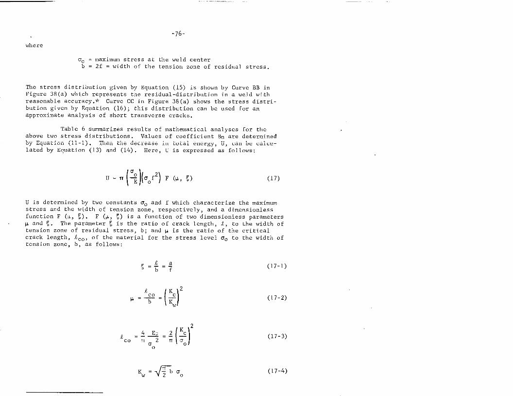
-76-
where
Do = maximum stress at the weld centerh = 2f = width of the tension zone of residual stress.
The stress distribution given by Equation (15) is shown by Curve BB inFigure 38(a) which represents the residual-distribution in a weld withreasonable accuracy.+: Curve CC in Figure 38(a) shows the stress distri-bution given by Equation (16); this distribution can be used for an
approximate analysis of short transverse cracks.
Table 6 summarizes results of mathematical analyses for theabcwe two stress distributions . Values of coefficient Bn are determinedby Equation (11-1). Then the decrease in total energy, U, can be calcu-lated by Equation (13) a“d (14). Here, U is expressed as follows:
(17)
U is determined by two constants O. and f which characterize the maximumstress and the width of tension zone, respectively, and a dimensionless
functian F (P, 5). F (Y, 5) is a function of two dimensionless parametersw and ~. The parameter E is the ratio of crack length, 1, to the width oftension zone of residual stress, b; and p is the ratio of the criticalcrack length, .tCo,of the material far the stress le”el 00 to the width oftension zone, b, as follows:
(17-2)
(17-3)
Kw = @J DO (17-4)
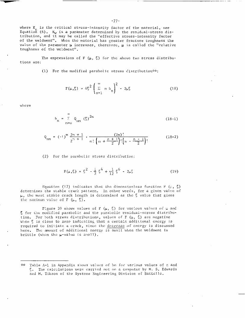
-77-
where K is the critical stress-intensity factor of the material, see
Eauatiok (6) . K.. is a Darameter determined bv the residual-stress clis-. .tribution, and it may be called the “effective stress-intensity factorof the weldment”. then the material has greater fracture toughness thevalue of the parameter p increases, therefore, # is called the “relativetoughness of the weldrnent?!.
The expressions of F (w, ~) for the above two stress distribu-tions are:
(1) For the modified parabolic stress distribution??::
(“=1). 2
F(w,E) = 4E2 Znb - Zv<n
where
m
b =XQn ~ (S)zm
~=o
Qm = (-1)”- . (Zm)!
2“’(” +*) ’(”-+)’
(18)
(18-1)
(18-2)
(2) For the parabolic stress distril,ution:
Equation (17) indicates that the dimensionless function F (c, <)determines the stable crack pattern. In other words, for a given value of
p, the most stable crack length is determined as the 5 value that givesthe maximum value of F (p, 5) .
Figure 39 shows values of F (w, 5) for various values of # and5 for the modified parabolic and the parabolic residual-stress distribu-tion. For both stress distributions, values of F (p, E) are negative
when E is close to zero indicating that a certain additional energy isrequired to initiate a crack, since the decrease of energy is discwsed
here. The amount of additional energy is small when the weldment isbrittle (when the p-value is small).
~:~:Table A-1 in Appendix shows values of bn for “arious values of n andF,. The calculations were carried out on a cornp”terby M. S. Edwardsand M. Tikson of the Systems Engineering Division 01 Battelle.
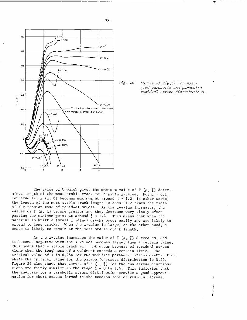
-
“P05
04
03
cl,
o I
o
-0.,
-020 , z
-78-
+
~,o
/’=0.01
-r#’=0.02
+ p ~0.0$
,.mb.l, c SW,, d>,,,,,.,
s,,,,,d,,,ri,.,’on
T$.=;1
4
.Fig.39. Curves of F(u ,<) ,Formodi-fied parabolic and parabolicresidua l–6tress distribution.
The value of X which gi”es the maximum value of F (~, ~) deter-mines length of the most stable crack for a gi”en ~-value. For F = 0.1,for example, F (w, ~) becomes maximum at around ~ = 1.2; in other words,the length of the most stable crack length is about 1.2 times the widthof the tension zone of residual stress .- As the k-value increases, thevalues of F (u, ~) becom’egreater and they decrease very slowly afterpassing the maximum point at around ~ = 1.4. Tlis means that when thematerial is brittle (small F value) cracks occur easily and are likely toextend to long cracks. When the p-”alue is large, on the other hand, acrack is likely to remain at the most stable crack length.
As the p-”alue increases the “al”e of F (&, ~) decreases, andit becomes negati”e when the q-”alues heccxnes larger than a certain “alue.This means that a stable crack will not occur because of residual stressalone when tbe toughness of a weldment exceeds a certain limit. Thecritical value of u is 0.254 for the modified parabolic stress clistributio”,while the critical value for the parabolic stress distribution is 0.29.Figure 39 also shows that curves of F (L, E) for the two stress distribu-tions are fairly similar in the range ~ = O to 1.4. This indicates thatthe analysis for a parabolic stress distribution pro”ide a good approxi-mation for short cracks formed in the tension zone of residual stress.
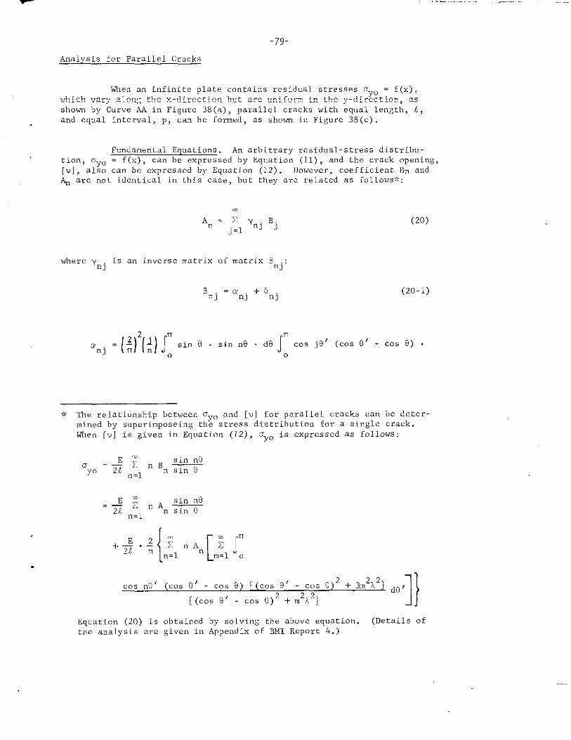
7
-79-
Analysis for Parallel Cracks
When an infinite plate contains residual stresses Oyo ~ f(x),which vary along the x-direction hut are uniform in the y-directmn, asshown by Curve AA in Figure 38(a), parallel cracks with equal length, A,and equal interval, p, can he formed, as shown in Figure 38(c) .
Fundamental Equations . An arbitrary residual-stress distribu-tion, oyo . f(x), can be expressed by Equation (11), and the crack opening,
[v], also can be expressed by Equation (12). However, coefficient Bn and~ are not identical in this case, but they are related as follows>’::
m
An= X ynj B.j.1 J
where ynj is an inverse matrix of matrix 3nj:
!3nj= LYnj+ &*j
‘nj = ($)’(~) ~ ‘in ‘ “ ‘in ‘e ‘e f: ‘Os ‘e’ (Cos “
(20)
(20-1)
COS 8) .
,? The relationship between oyo and [v] for parallel cracks can be deter-mined by superimposing the stress distribution for a single crack.When [v] is given in Equation (12), Gyo is expressed as follows:
ccsin nO
rJ=” XnB—ycl 21 *=1 n sin 9
{(2
cc’sne’ (=OS e’ - COS e) COS e’+ 3m2A2
- Cos e)-.
} 1}
de ‘
[(=OS a’ - COS e)2 + ~2A2)
Equation (2o) is obtained by solving the above equation. (Details of
the analysis are given in Appendix of BMI Report 4.)
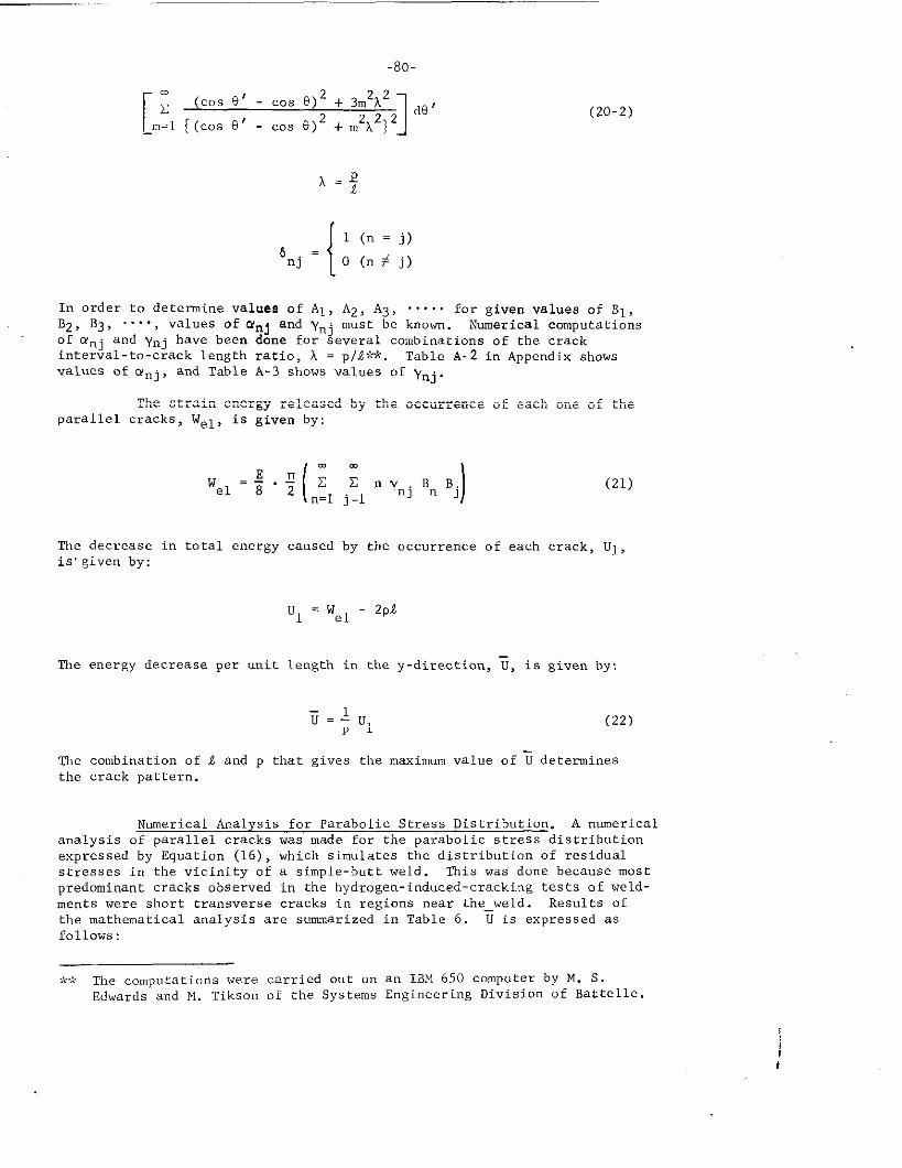
,.,.
-80-
[
.(COS 8’ - ,OS e)
2 + ~m2k2z
1
de ‘
_m=I {tcOS e’ - COS 9)2 + ~z~z]z
(20-2)
{
l(n=j)
6nj =O(n #j)
In order to determine valuee of Al , Az, A3, ..... for given values of BI,
Bz> B3, ““”-, values of Onj and ‘ynjmust be known. Numerical computationsof Wnj and Ynj have been done for several combinations of the crackinterval-to-crack length ratio, A = p\i+:*. Table A-2 in Appendix showsvalues of anj, and Table A-3 shows “alues of ynj.
The strain energy released by the occurrence of each one of theparallel cracks, Wel, is given by:
(21)
The decrease in total energy caused by the occurrence of each crack, U1,is,given by:
Ul=w - 2plel
The energy decrease per unit length in the y-direction, ~, is given by:
T=JUpl
(22)
‘he combination of 1 and p that gives the maximum value of fideterminesthe crack pattern.
Numerical Analysis for Parabolic Stress Distribution. A numericalanalysis of parallel cracks was made for the parabolic stress distributionexpressed by Equation (16), which simulates the distribution of residualstresses in the vicinity of a simple-butt weld. This was done because mostpredominant cracks observed in the hydrogen-induced-cracking tests of weld-ments were short transverse cracks in regions mar the_welcl. Results ofthe mathematical analysis are summarized in Table 6. U is expressed asfollows :
9<,?The computations were carried out u“ an IBM 650 computer by M. S.Edwards and M. Tikson of the Systems Engineering Division of Battelle.
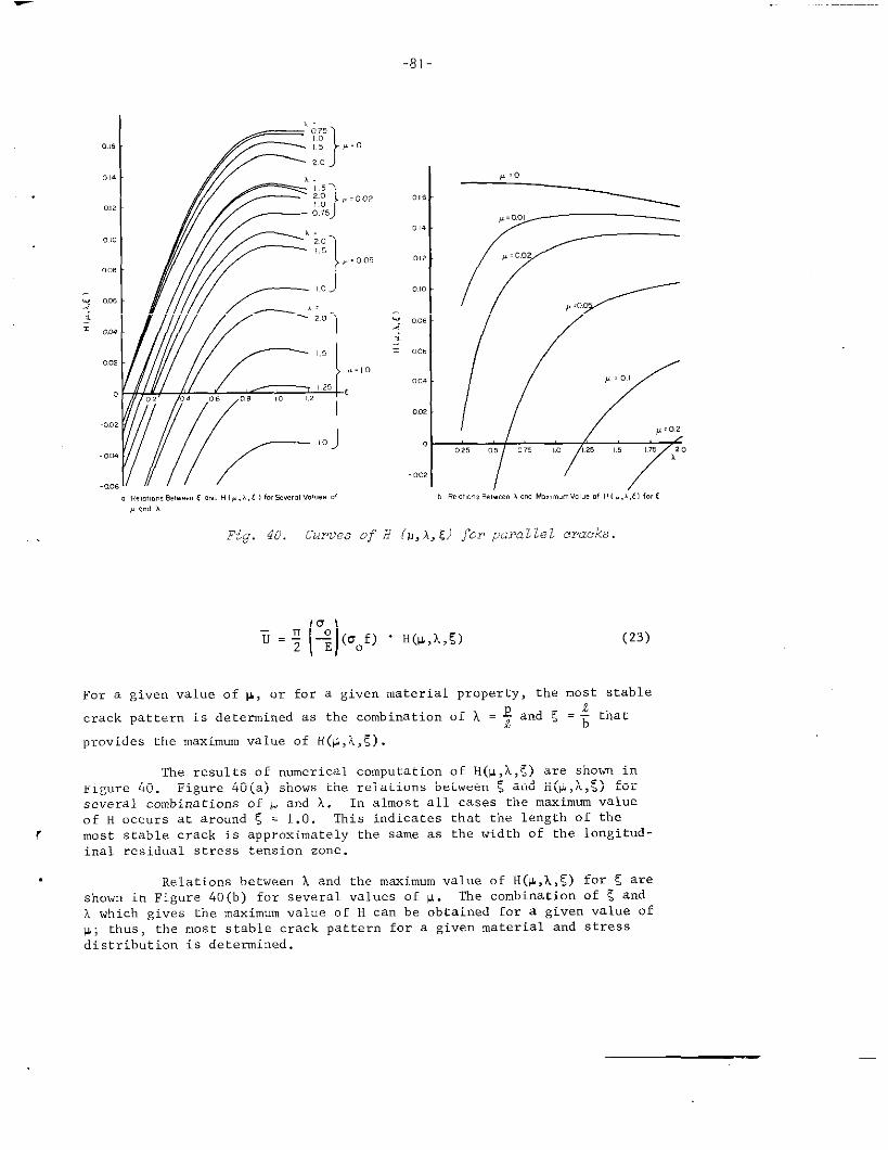
-81-
,.
.0,
0b0:
.0,02
XZ’———20 J
y 0.75)
L
~
20
J
6,5
,. 00,
.0
,:2.0
,,
, = ,.0
c, 04 ., 08 ,. ,2
rll ,0
0...
.“.. r’”o .e,o!,m.,W.-e. cnodH ,,,,,(1forS,..,.,“01.,s.1
,=.
,=0,0,
, ,., A
Fig. 40. curves of B (v,A,C) fcr pczmllel cracks.
(23)
For a given value of W, or for a given material property, the most stable
crack pattern is determined as the combination of A = $ and ! = ~ that
provides the maximum value of H(w,k,E) .
The results of numerical computation of H(v,A,~) are shown inFigure 40. Figure 40(a) shows the relations between E and H(Y,A,~) fOrseveral combinations of p and h. In almost all cases the maximum value
of H occurs at around !,= 1.0. This indicates that the length of the
r most stable crack is approximately the same as the width of the longitud-inal residual stress tension zone.
. Relations between A and the maximum value of H(#,k,5) for C areshown in Figure 40(b) for several values of +. ‘he combination of 5 and
A which gives the maximum value of H can be obtained for a given value of
P; thus, the most stable crack pattern for a given material and stressdistribution is determined.
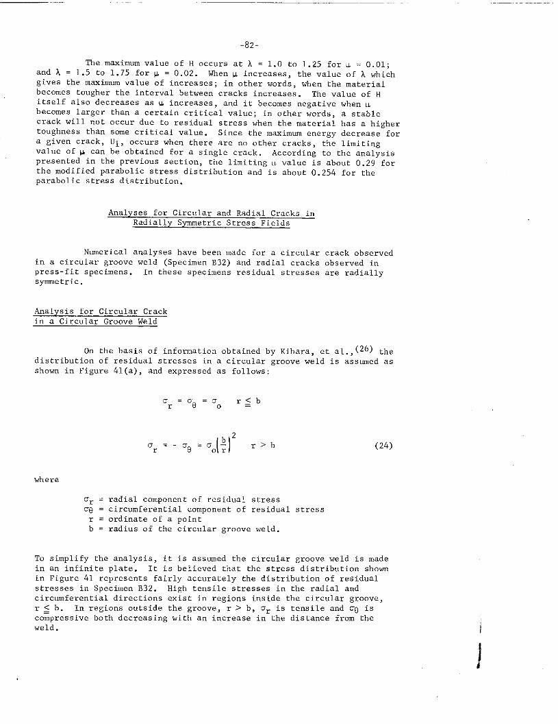
-82-
The maximum value of H occurs at A = 1.0 to 1.25 for u = 0.01;and L = 1.5 to 1.75 for ~ = 0.02. When w increases, the value of A whichgives the maximum value of increases ; in other words, when the materialbecomes tougher the interval between cracks increases . The value of Hitself also decreases as ~ increases, and it becomes negative when wbecomes larger than a certain critical value; in other words, a stablecrack will not occur due to residual stress when the material has a highertoughness than some critical “alue. Since the maximum energy decrease for
a given crack, UI, occurs when there are no other cracks, the limitingvalue of w can be obtained for a single crack. According to the analysis
presented in the previous section, the limiting u value is about 0.29 forthe modified parabolic stress distribution and is about 0.254 for theparabolic stress distribution.
Analyses for Circular and Radial Cracks inRadially Symmetric Stress Fields
Numerical analyses have been made for a circular crack obserw?d
in a circular groove weld (Specimen B32) and radial cracks observed inpress-fit specimens. In these specimens ~esidual stresses are radiallysymetric.
Analysis for Circular Crackin a Circular Grcxwe Weld
On the basis of information obtained by Kihara, et al.,(26) thedistribution of residual stresses in a circular groove weld is assumed asshown in Figure 41(a), and expressed as follows:
o =’s=0r 80
r<b—
u=-crBr = 0.($)2 r> b
where
or = radial component of residual stress
% = circumferential component of residual stressr = ordinate of a pointb = radius of the circular groove weld.
(24)
To simplify the analysis, it is assumed the circular growe weld is made
in an infinite plate. It is believed that the stress distribution shownin Figwe 41 represents fairly accurately the distribution of residualstresses in Specimen B32. High tensile stresses i“ the radial andcircumferential directions exist in regions inside the circular groove,r<b. In regions outside the groove, r > b, or is tensile and o~ iscompressive both decreasing with a“ increase in the distance from theweld. i
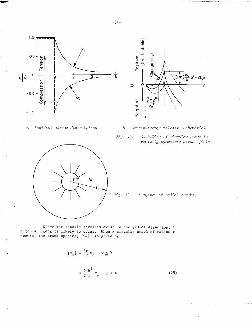
,.-.. ..._ —...._..,.
-83-
1.0
. 0.5
1°b b“
-0.5
-1.0
a. Residual-stress distribution b. Strain-energy release (Schematic)
Fig. 41. Stability of circular crack inraiially sywnwt~ic stress field.
Fig. 42. A system of radial cracks.
.
Since the tensile stresses exist in the radial direction, acircular crack is likely to occur. men a circular crack of radius roccurs, the crack opening, [vr], is given by:
(25)
-84-
The decrease in total energy caused by the occurrence of a circular crack,U, is:
~=&nr202Eo
- 4nrp r~b—
2nb402Er20
- 4nrp r>b (26)
The relation between the radius of a circular crack, r, and Uis shown in Figure 41(b) . The value of U becomes a maxirnwnof r = b; inother words, a crack is most likely to occur at the outer edge of the
highly stressed area. In Specimen B32, a circular crack occurred justoutside the circular groove weld, as shown in Figure 12> In order thata circular crack occurs, the maximum stress Do rmst be greater than tbe
critical stress crcrgiven below:
Analysis for Radial Cracksin Press-Fit Specimens
(27)
Systems of radial cracks, as shown in Figure 22, were formedduring the hydrogen-induced-cracking tests of press-fit specimens. Thecracks were caused by the tensile circumferential stress. When stresses
increased, cracks became longer and the number of cracks increased. When
stresses exceeded a certain value, complete fracture of the specimen took
place. An approximate analysis was made of a system of radial cracks.
When a material contains residual stresses of a radially sym-metric distribution as gi”en by Equation (1), a system of radial cracks ofequal length and located in equal intervals will be produced, as shown inFigure 42. In calculating the decrease of elastic strain emrgy due to
cracking, we (per unit plate thickness) , it is assmned, as a first approxim-ation, that some percentage of tbe strain energy stored in the area wherecracks occur is released due to the formation of cracks:
2n rc
We=wH-{
2+ (Ur
1
+ 08) - ; Uroo dr rdSl
0‘1
$: Several short transverse cracks observed on Specimen B32 are believedto be caused by tensile residual stresses in the direction of weldingcaused by the longitudinal shrinkage of the weld.
. where, cracks are formed from r = r~ to r = Kc. The value of e increases
and approaches 1 when the number of cracks increases.
The rate of strain-energy release due to the extension ofdw
cracks, ~ is:dr ‘
(29)
where
()r 4
2
[)
3
fK,~=-1X=c+
II
>
‘1 (1 + X2)2 ‘1 (1 + %2)2 r.(29-1)
The equilibrium condition for cracking is given by:
dwe K2
x=n.2p= n.+
Equation (30) can be expressed as follows:
(30)
(31)
Thus the Kc value of the hydrogen-embrittled material can be determinedfrom knowing the crack pattern.
Application of Analytical Investigations to theInterpretation of Experimental Results
Determination of KC Value ofthe Hydrogen- Mnbrittled Materials
Equation (31) indicates that the Kc value of the hydrOgen-embrittled material can be determined from the knowledge of the crack
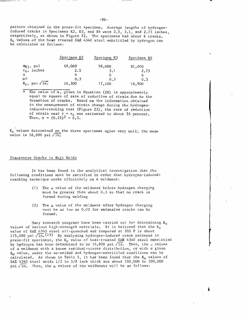
-86-
pattem obtained in the press-fit specimen. Average lengths of hydrogen-induced cracks in Specimens K2, K3, and K4 were 2.5, 3.1, and 2.75 in~he~,respectively, as shown in Figure 22. The specimens had about 6 cracks.~ values of the heat treated SAE 434o steel ernbrittledby hydrogen canbe calculated as follows:
Specimen K2 Specimen K3 Specimen K4
gel, psi 68,000 98,OOO 81,000rc, inches 2.5 3.1 2.75n 6 6 6a $< 0.3 0.3K., psi fi
0.316,300 17,100 16,900
~~ The value of o., given in Equation (28) is approximatelyequal to square of rate of reduction of strain due to theformation of cracks. Based on the information obtainedin the measurement of strain change during the hydrogen-induced-cracking test (Figure 23), the rate of reductionof strain near r = rc was estimated to about 55 percent.Then, a = (0.55)2 = 0.3.
Kc values determined on the three specimens agree very well; the meanvalue is 16,800 psi m
Transverse Cracks in Butt Weids
It has been found in the analytical investigation that thefollowing conditions must be satisfied in order that hydrogen-induced-cracking technique works effectively on a weldment:
(1) The p value of the weldment before hydrogen chargingmust be greater than about 0.3 s,othat no crack isformed during welding
(2) The y value of the weldment after hydrogen chargingmust be as low as 0.02 for extensive cracks can beformed .
Many research programs have been carried out for determining Kcvalues of various high-strength materials. It is believed that the Kc
value of SAE 4340 steel oil-quenched and tempered at 500 F is about175,000 psi =.(19) By analyzing hydrogen-induced crack patterns in
press-fit specimens, the Kc value of heat-treated SAE 4340 steel embrittledby hydrogen has been determined to be 16,800 psi fi. Then, the u valuesof a weldment with a known residual-stress distribution, or with a givenKw value, under the as-welded and hydrogen-embrittled conditions can becalculated. As shown in Table 5, it has been found that the ~ values ofSAE 434o steel welds 1/2 to 5/8 inch thick are about 100,000 to 200,000psi 6. Then, the ILvalues of the weldments will be as follows:
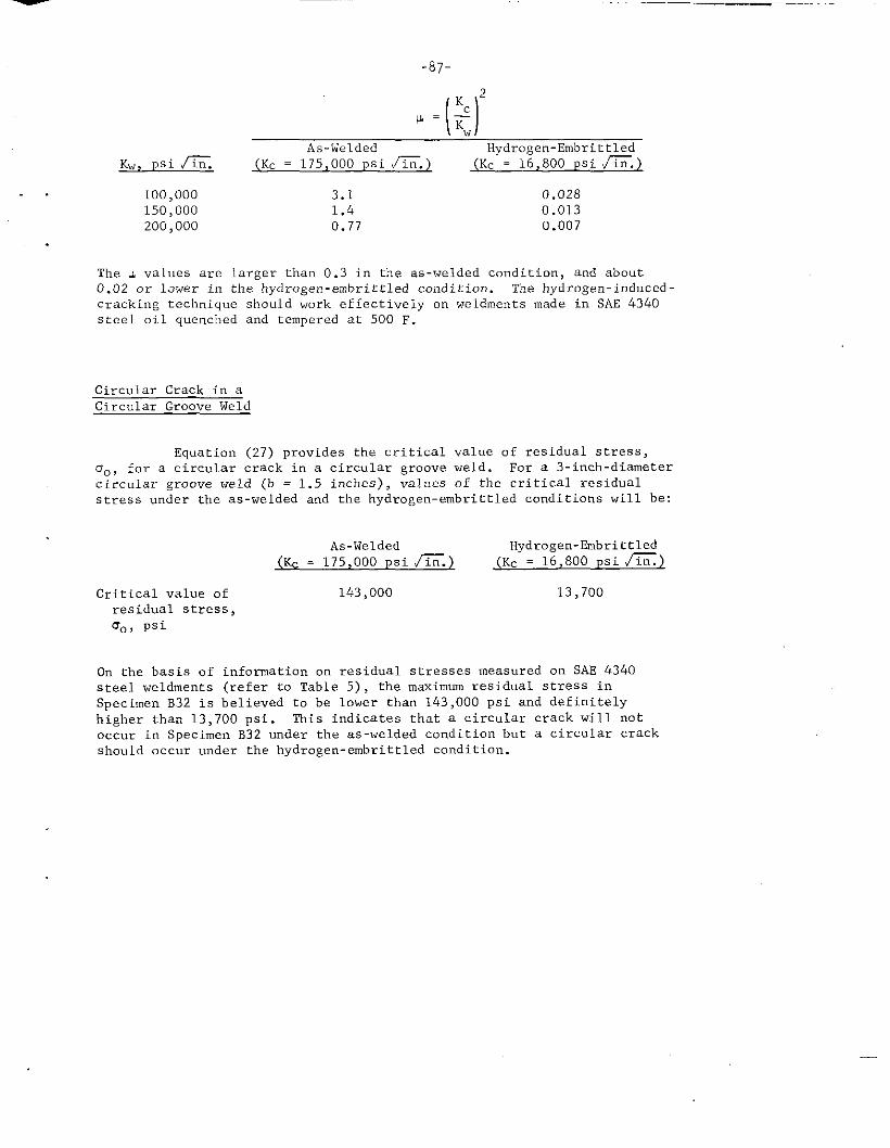
-87-
. .
Kc
[1
2
~=Tw
As-Welded Hydrogen-Embrittled
Kw , *si K. (Kc = 175,000 psi fi. } (Kc = 16,800 psi =.)
100,000 3.1 0.028150,000 1.4 0.013200,000 0.77 0.007
The p values are larger than 0.3 in the as-welded condition, and about0.02 or lower in the hydrogen -embrittled condition. The hydrogen-induced-cracking technique should work effectively on weldments made in SAE 4340steel oil quenched and tempered at 500 F.
Circular Crack in aCircular Groove Weld
Equation (27) provides the critical value of residual stress,O., for a circular crack in a circular groove weld. For a 3-inch-diametercircular groove weld (b = 1.5 inches), values of tbe critical residualst~ess under the as-welded and the hydrogen-embrittled conditions will be:
As-Welded Hydrogen-&nbrittled
(S% = 175,000 psi =.) (Kc = 16,800 psi ~)
Critical value of 143>000 13,700
residual stress,O., psi
On the basis of information on residual stresses measured on SAE 4340steel weldments (refer to Table 5) , the maximum residual stress inSpecimen B32 is believed to be lower than 143,000 psi and definitelyhigher than 13,700 psi. This indicates that a circular crack will notoccur in Specimen B32 under the as-welded condition but a circular crackshwld occur under the hydrogen- embrittled condition.
-88-
SIJMMARYANC DISCUSSIONS OF FINOINGS OBTAINED IN THEEXI?ERIM?NTAL AWE ANALYTICAL INVTSTICATIONS
Experimental Investigations
Hydro Een-Induced-Cracking Tests on Weldments
Experimental hydrogen-induced-cracking tests were conducted on 45 weld-nmnts including 29 -weldnwnts in SK? 43L0 steel, 6 i“ a commercial high-strtmgthstructural steel (presently supplied under ASTM A516, Grade F) , 4 in HY-80 steel,and 6 in mild steel. In order to produce a variety of residual-stress distribu-tions, the weldments were made i“ “a.rious designs and with various welding pro-cedures. The weldments were electrolytically charged with hydrogen to producehyd~ogen-induced cracks The experimental results are summarized in Table 3,
Effects of Type of Steel, Heat Treatment, and Plate Thickness. The typeof steel and heat treatment had significant effects on the tendency for hydrogen-induced cracking.
Extensive and systematic crack patterns were found in weldments madein SAF 4340 steel oil quenched and tempered at 500 and 600 F, (Only one speci-men was prepared with steel temperate at 600 F.) Cracks were found afterhydrogen charging for less than a few hours. In butt joints made from SAE 4340steel oil quenched and tempered at 750 or 1000 F, fairly systematic cracks wereobtained after hydrogen charging for several hours. No cracks were observed ina weldment made from SAE 4340 steel in the as-rolled condition after hydrogencharging for 14 hours.
Hydrogen-induced-cracking tests were made on five weldtmmts preparedfrom a conunercialhigh-strength structural steel heat treated to the “hardcondition”. Cracks were found in three specimens after hydrogen charging for 5to 24 hours. However, crack patterns were less pronounced than those obtainedon heat-treated SAE 434o steel specimens. Cracks were not produced in a weldmentmade from a conunercialhigh-strength structural steel heat treated to the “softcredition” after hydrogen charging for 4-1/2 hours.
With regard to HY-80 steel specimens, no cracks were obser”ed in twol/2-inch-thick weldments after hydrogen charging for 20 and 140-1/2 hours.Small cracks were found in the heat-affected zone in a weldment 1-1/2 inchesthick (after 22 hours) , and a series of tran.werse cracks was obtained in aweldment 2 inches thick (after 216 hours)
With regard to mild-steel specimens, no cracks were obser”ed on fourweldments 1/2 and 3/4 inch thick after hydrogen cbargi”g for “p to 126-1/2 hours.Very small cracks were found in the heat-affected zone of a butt joint 2 inchesthick after hydrogen charging for 379 hours. Very small cracks also were foundin the heat-affected zone in a butt joint 5/8 by 24 by 38 inches after repeatedhydrogen charging (total time: 219 hours) followed by cooling to -30 F toernbrittlethe material.
Sirncoe, et al. (7) made an i“v. stigation of l,ydrogen-induced delayed
brittle failure of SAF 4340 steel heat treated to different strengths. Relation-ships were obtained between the applied stress and the time to rupture while the
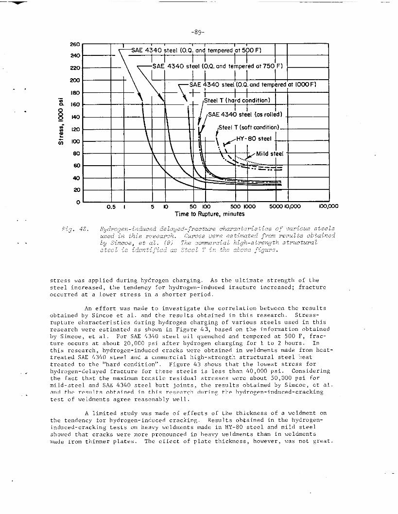
-89-
240
220
200
I80
60
40
20
00.5 I 50 50 Im 500 000 5CO0 Io,ooo KK@30
Ttme to Rupture, minutes
stress was applied during hydrogen charging. As the ultimate strength of thesteel increased, the tendency for hydrogen-induced fracture increased; fractureoccurred at a lower stress in a shorter period.
An effort was made to investigate the correlation between the resultsobtained by Simcoe et al. and the results obtained in this research. Stress-r“pture characteristics during hydrogen charging of various steels used in thisresearch were estimated as shown in Figure 43, based on the information obtainedby Simcoe, et al. For SAF 4340 steel oil quenched and tempered at 500 F, frac-ture occurs at about 20,000 psi after hydrogen chazging for 1 to 2 hours. Inthis research, hydrogen-induced cracks were obtained in weldments made from heat-treated SAE 4340 steel and a commercial high-strength structural steel heattreated to the “hard condition” Figure 43 shows that the lowest stress for
. . hydrogen-delayed fracture for these steels is less than 40,000 psi. Consideringthe fact that the maximum tensile residual stresses were about 50,000 psi formild-steel a“d SAS 4340 steel butt joints, the results obtained by Simcoe, et al.and the results obtained in this research during the hydrogen-induced-crackingtest of weldments agree reasonably well.
A limited study was made of effects of the thickness of a weldment onthe tendency for hydrogen- induced cracking. Results obtained in tbe bydrogen-
induced-cracking tests o“ heavy weldrnents made in HY-80 steel and mild steel
showed that cracks were more pronounced in heavy weldments than in weldments
made from thinner plates. The effect of plate thickness, houever, was not sreat
-90-
Characteristics of Crack Patterns in SAE 4340 Weldments. Hydrogen-induced-cracking tests were conducted on several complex weldments made from
SAE 4340 steel oil quenched and then tempered at 500 F, Complex butt joints, acircular-groove weld, continuous and intermittent fillet joints, and complexstructures were tested. Various crack patterns that could be related to theresidual-stress distribution were obtained. Three types of crack pattern canbe identified.
The first type is characterized by a series of short transverse cracksadjacent to a weld. This type of crack, which occurs in almost every weld, is aresult of the lo”git”dinal tensile residual stresses that are always present inthe vicinity of a weld, In a simple butt joint, this type of crack is mostpredominant. In most cases, the crack pattern on om surface of a specimen isrepeated on the other side, This shows that residual stresses of nearly the samemagnitude are produced cm both surfaces
The second type of crack pattern is one caused by stress concentration.The concentration of residual stress can be produced by an abrupt interruption ofwelding as well as by an abrupt chmge i“ section. This type of crack gtmerallyhas a parabolic form a“d penetrates into the base metal to form a long crack.
The third type of crack pattern ccmtains cracks caused by residualstresses tram”erse to a weld, and bending stresses associated with angulardistortion d“e to fillet welding.
Results of the hydrogen-induced-cracking test on a weldment made by theBattelle Narrow-Gap welding process indicated that the tension zone of ~e~idua~stresses produced by the Narrow-Gap process is narrower than that produced by theordinary shielded-metal-arc process,
Initiation and Propagation of Hydrogen-Induced Cracks. Initia,tio” andpropagation of hydrogen-induced cracks were observed on se”eral specimens whichwere placed in a container which had a transparent wall during hydrogen charging,
On weldrnentsmade from SAF 4340 steel oil quenched a“d tempered at
500 F, cracks were first observed after hydrogen charging for about 45 mi””tes.
Apparently, there is an incubation period before cracks occur. This has bee”pointed o“t by Troiano. (6) Most cracks were formed in a short period (usuallyin a few minutes) after the first crack was observed.
When the hydrogen charging was continued for an extended period some ofthe cracks--uswilly one or two--in a specimen grew extensively, Cracks alsosometimes grew greatly after hydrogen charging was stopped. The delayed growthof cracks was caused by the hydrogen that remained i“ specimens after thebydroge”-induced-cracking test
Whtm a crack grows extensively , residual stresses i“ a large areasurrounding the crack are released, and the tendency to form other cracks i“adjacent areas decreases. As a result, a few lmg cracks, instead of a seriesof short cracks , are formed even in an area where the distribution of residualstress is ““iform. Since the extended cracks are likely to be misinterpreted asan evidence of stress co”centratio”, it is ad”isable to try to prevent theocc”rre”ce of the irregularly extended cracks
First , it is advisable not to continue hydrogen charging longer thannecessary to produce hydrogen- induced cracks Co”ti”uously obser”i”g a specimenduring testing will permit the determination of the proper time to stop the
—
-91-
hydrogen-induced-cracking test. Second, it is recommended that a specimen bebaked after testing to remove tbe residual hydrogen. Baking in a furnace at400 F for a few hours appears to be adequate.
Effect of Mechanical Stress Relieving. Hydrogen-induced-cracking tests
. . were made on weldme”ts (bead-on-plate type) that had been mechanically stressrelieved. Cracks were found in as-welded specirmms a“d specimens that had bee”mechanically stress relieved by Ioadi”g, i“ a testing machine, up to 60 percc?”tof the yield stress, However,. . cracks were not found in tbe specimen that had beenloaded to 80 percent of the yield stress. The results indicate that hydrogen-induced cracking is stress sensiti”e, and “ot plastic-strain sensitive; in otherwords , cracks obtained in a welded specimen are caused by residual stresses, not
by Plastic deformation produced by welding.
Hydrogen-Induced-Cracking Test on Press-Fit Specimens
Radial cracks were found in the press-fit specimens made from SAF 4340steel oil quenched a“d then tempered at 500 F a“d the commercial high-strength
heat-treated steel. The test results indicate that hydrogen-induced cracks ca”be caused by stresses produced by purely elastic deformation.
An attempt also was made to investigate the correlation between thetest results obtained on the press-fit specimens and those obtained by Sirncoe,
. . et al.(7) Since values of the circmnferential stress at the inmr circle, OBI,were determined, the regions where circumferential stresses, O. , exceeded20,000 psi (refer to Figure 21) are determined as follows:
. .
Specimen Kl: r <3.9 inches
Specimen K2: r <2.5 inches
Specimen K3: r <3.1 inches
Specimen K4: r <2,75 inches
Complete fracture occurred in Specimen K1 in which circwnferentialstress exceeded 20,000 psi in most areas. In studying the crack pattern obtainedin Specimens K2, K3, and K4, circles of 2.5, 3,1, and 2,75 inches are drawn inFigures 22b, c, and d, respectively, The average crack lengths coincided i-eason-ably well with the circles; although i“ Specimen K4, one crack extended greatlyafter tb,ehydrogen-induced-cracking test was completed and the specimen fracturedcompletely. The results indicate that the critical stress required for thepropagation of hydrogen- i”d”ced cracks is about 20,000 psi for SAE 4340 steeloil quenched and tempered at 500 F,
,Stress-Corrosion-Cracking Tests cm Weldme”ts
A limited study was made of stress-corrosion cracking of welded speci-mens Weldments were made from “ario”s steels i“cludi”g mild steel, HY-80 steel ,the commercial high-strength structural steel, and SAE 4340 steel. Specimenswere irmnersedi“ a boiling aq”eo”s solutim consisting of 60 percent of Ca(N03)2and 4 percent NH4N03.
In mild-steel specimens, cracks were observed in two of the five speci-mens tested, In specimens made from steels of higher strength, cracks were
————. —
-92-
observed in all (fine) specimens tested. A system of transverse cracks wasobtained in the stress-corrosion-cracking test on a specimen made from the com-mercial high-strength treated steel. Tbe crack pattern was similar to thoseobtained in the hydrogen-induced-cracking tests of SAE 4340 steel specimens. Asmall number of relatively long tra”s”erse cracks were obtained in the stress-corrosion-era,cki”g tests on specimens made from mild steel , HY-80 steel, a“dSAE 4340 steel.
Metal lographic Examinations of Cracks
Metal lographic examinations were made of sections cut through the endsof cracks. In the commercial high-strength structural steel , hydrogen-inducedcracks were tra”sgranular, while stress-corrosion-induced cracks were i“tergra”-“lar. In heat-treated SAE 4340 steel specimens, cracks produced by both types oftests were i“tergra.nular.
Measurement of Residual Stresses by Stress-Relaxation Techniques
lleasurements of residual stresses by stress-relaxation techniques usingstrain gages were made on 8 weldments in mild steel and SAE 4340 steel, including6 butt joints up to 24 by 38 inches in size a“d 2 complex welded structures,Distortions due to welding of the complex structures also were measured. Theexperimental results are summarized in Table 5.
The most important finding obtained in this phase of research is thatdistributions of residual stresses in mild-steel a“d SAE 4340 steel weld”ents
were quite similar. It was proved in butt joints as well as in complex weldedstructures. In all welded specimens, high-tensile longitudinal residual stresseswere found in regions near the weld and compressive lo”gitudi.nal stresses i“regions away from the weld. Values of the maximum longitudinal residual stressat the weld center, Do , were 45,000 to 75,000 psi. SAE 4340 steel specimens
appeared tO have higher residual stresses than mild-steel specimens, but thedifferemce was minor. The widths of the tension zone of longitudinal residualstress were 2.5 to 6 inches,
The following experimental e“idences also were obtained on the magnitudeand distribution of residual stresses i“ SAE 4340 steel weldments:
(1) Whether or not the weld reinforcement was remo”ed by grinding hadlittle effect on the magnitude and distribution of residualstresses, as shown in Table 5.
(2) The results of measurement of residual stresses along the weld
show that residual stresses reached the maximum “alws in thecentral portion of the 38-inch-long butt joint (see Figure 32)
These experimental evidences indicate that the residual stresses i“ heat-treatedSAE 4340 steel weldments are considerably lower than the yield strengths of thebase metal and the weld metal that were 224,000 psi and about 150,000 psi,respectively.
Investigations of the mechanisms which caused residual stresses inSAE 4340 steel weldments to be 10V were not carried cwt in this research. Thepreheating and interpass te”perat”ce at 400 F applied to SAE 4340 steel weldmentsprobably contributed to reduce residual stress to some extent. However, theremight be limitations in the magnitude of residual stresses which are primarily
-—
-93-
caused by plastic deformation as a result of tberrnalexpansion and contractionduring welding. Tbe value of coefficient of linear tbennal exuansion of steel is6,5 rn~croi”ch~s/inch/F, while modulus of elasticity is shout 30 x 106 psi at roomtemperature. Tbe thermal strain produced by a temperature change of 250 F isequal to the elastic strain which cot-responds to the stress of 45,OOO psi. Thisindicates that in a mild-steel weldrnent contraction of the material during coolingcan easily produce residual stresses as high as the yield stress. However, tem-. .perature changes of 750 and 1100 F are required to produce thermal strains equalto elastic strains which corresponds to the stresses of 150,000 psi (yield stressof weld metal made from E15016 electrodes) a“d 224,000 psi (yield stress ofSAE 4340 steel oil quenched and tempered at 500 F) , respectively. Since SAE 4340steel softens drastically at temperatures above about 800 F, it may not he possi-ble to produce high residual stresses dui-i”gthe welding thermal cycle. Marestudy of this problem is “ceded.
Analytical Investigations
General Theory of Crack Pattern Produced by Residual Stresses
An attempt was made to develop a general theory of the crack patternproduced in a solid containing residual stresses by modifying the Griffith-Irwinfracture-mechanics theory. It has been fcmnd that, by using the energy concept,
the crack pattern that is most likely to occur can be determined theoreticallywhen the residual-stress distribution and properties of the material are known..However, a unique solution of residual-stress distribution cannot be determinedfrom knowledge of the crack pattern because of ind.stenninate coefficients associ-ated with the integration of the unknown functions. Further mathematical analyses
. .were made of simple crack patterns including (1) transverse cracks in butt-weldedspecimens, and (2) circular and radial cracks in radially syrmnetricstress fields
Analysis for Transverse Cracks in Butt-Welded Specimens
Mathematical analyses were made of a system of transverse cracks whichwas conunonlyobtained in butt-welded specimens during the hydrogt?n-induced-crackingtest. Nmnerical analyses were made of two mathematically expressed stress distri-butions which simulate the residual-stress distributions in a butt weld. Aparabolic stress distribution was used i“ an .malysis of short transverse cracks,and a modified parabolic-stress distribution was used in an analysis of a crackwhich extended into the region where residual stresses were originally compressive.
A dimensionless parameter, +, which is called “relative toughness of aweldment (against transverse cracking),,has been introduced to characterize the
tendency for hydrogen-induced cracking of a weldment The parameter is determinedby the residual-stress distribution a“d the properties of the material as follows:
#
[)2
Kcp=TV
where Kc = critical stress-intensity factor of the material
K+,,= o. G = effective stress-intensity factor of the re.sidwl stresses
‘JO= maximum longitudinal residual stress at the weld center
b = width of the tensim zone of longitudinal residualstresses.
The
(1)
(2)
(3)
(4)
The
-94-
following results have been obtained:
A series of cracks will be obtaim?d when the p-value of a weld-ment is smaller than approximately 0.02.
NO crack will be obtained when the +-value is larger than about0.3. The critical value of h is 0.29 for the parabolic stressdistribution, and O.25 for the modified parabolic stressdistribution,
The length of stable serial cracks is approximately the same asthe width of the tension mme.
When a weldment is very brittle, say w-value is around 0.01, oneor a few cracks of a series of cracks can easily penetrate intothe region where residual stresses were originally compressive.
results indicate that there are limitations cm the properties ofmaterial to be used in the hydrogen-induced-cracking test. The u-value of a
weldment before hydrogen charging must be larger than about O.3, otherwisecracking may occur without hydrogen charging. The +-value of the weldme”t ,hm.rwer, must decrease to about 0.02 during hydrogen chargi”.gi“ order forsystematic cracks to occur. When c=acks a,e formed due to hydrogen, it isrecommended not to charge for too long a time , since cracks may grow beyond themost stable crack length.
Analysis for Circular and Radial Cracks in Radially S.,munetricStress Fields
A mathematical analysis was made, i“ previous research, of a circularcrack obtained in a circular-groove weld. It was found that tbe most stablecircular crack occurs just outside the highly stressed area. An analysis alsowas made of a system of radial cracks obtained in press-fit specimens. Anequation has been developed to estimate the critical crack length of the materialfrom the crack pattern.
Applications of Analytical Investigations to the Interpretation ofExperimental Results
Attempts have bee” made to apply the information obtained in the ana-lytical investigations to the interpretation of crack patterns obtained in theexperimental hydrogen-induced-cracking tests. Crack patterns obtained in press-fit specimens were analyzed to determine the Kc “alue of heat-treated SAE 4340under the presence of hydrogen. ‘TheKc value was 16,800 psi Rn. Accordingto information obtained by other investigators, the Kc value of heat-treatedSAE 4340 steel in air is about 175,000 psi /%. indicating that the Kc “alueis decreased by about 9077by hydrogen charging. According to the results of
measurement of residual stresses, the Kc values of SAE 4340 steel weldments were100,000 to 200,000 psi ~. Then, the F values of SAE 4340 steel weldments are
apparently higher than 0.3 in the as-welded condit<on, but will be as low as oreven below O.02 after hydrogen charging. The results indicate that the hydrogen-induced-cracking technique works effectively cm weldments made in heat-treatedSAE 4340 steel,
-95-
CONCLUSIONS
On the basis ofanalytical investigationshydrogen-induced-cracking
the information obtained i“ tbe experimental andconducted in this research it can be concluded that thetechniques are usel”l for studying the distribution of
residual stresses in a complex weldment
It has been fo””d chat the hydrogen-induced-cracking technique works.
very effectively on weldments made i“ heat-treated SAF 4340 steel. Systematic
crack patterns that could be related to the residual-stress distribution wereobtained on weldments with various designs and made with various procedures. Italso has been found that distribution of residual stresses in weldments made inmild steel and heat-treated S.4E4340 steel are similar. Therefore, it is recom-mended that experimental hydrogen-induced-cracking tests be made on veldrne”ts inheat-treated SAE 4340 steel.
Oil q“e”cb from 1550 F followed by tenpering at 500 F for 1 hour appearsto be an adequate beat-treatment conditim for the base plate. Cracks are usuallyformed after hydrogen charging for an hour or less. Charging should not be con-tinued for longer than necessary to produce the initial crack patter”. Bakingthe specimen (at about 400 F) after the hydrogen charging to remove remaininghydrogen is recommended. These procedures help to pre”ent the occurrence ofirregular cracks which may cmse a rnisinterpretatim of the crack patter”. Crackpatterns obtained in “ario”s types of treldrnentscan be classified as follows:
(1) A system of short transverse cracks which are caused by thelongitudinal tensile stresses in the vicinity of a weld
(2) Cracks caused by a concentration of residual stress as a resultof an abrupt interruption of welding or an abrupt structuralchange in a weldment
(3) Cracks caused by residual stresses transverse to a weld, bendingstrssses associated with angular distortion, and other secondarystresses.
Hydrogen-induced cracking is stress sensit?”e rather than plastic-strainsensiti”e This has been pro”ed by hydrogen-induced-cracking tests on mechanicallystress-relieved specimens a“d press-fit specimens in which residual stresses wereproduced by purely elastic deformation,
The l,ydrogc”-i”d”ced-cracking technique may be used as a method ofdenvnstrating existence of residual stress in weldments made from steels of lowerstrength. when steel of lower strength is used, longer charging time is requiredto produce cracks , and crack pattei-”sare less pronounced, The hydrogen- induced-
. . cracking technique, houe”er, does “ot seem to work on mild-steel weldments.
Analytical in”estigatio”s of crack patterms have been made. Mathematicalequations have been de”eloped to express relationships among (1) the resid”.al-
stress distribution, (2) properties of the material, and (3) the crack patter”.The analytical in”estigatio”s are useful for e“.alua.ti”gcrack patterns obtained
expcrine”tally.
.96.
FUTURE WORX
Phase 1. Use of the Hydrogen-Induced-Cracking Technique.foi-Studying Practical Fabrication Problems
In the design and fabrication af welded ships, there are a nurnbei-ofpractical problems related to the selection of proper design details a“d weldingprocedures to avoid excessive concentration of residual stresses and possiblecracking during and after welding. It is recamnended that research on the use of
the hydrogen-induced-cracking technique for studying these practical problems becarried out. It has been found that distributions of residual stresses in mild-steel and SAE 4340 steel weldments are similar. Therefore, structural modelsmade in SAE 4340 steel could be used for studying residual-stress problems i“ship structures made in mild steel or high-strength ship steels.
Phase 2. Residual Stresses in Weldme”ts i“
HiRh-Strength Materials
It has been found in this research that magnitudes and distributionsof residual stresses in mild-steel and SAE 4340 steel weldments are similar.However, mechanisms which caused residual stresses in 4340 steel veldments tobe lower than the yield stresses of tbe material have not bee” established, Italso has not been found whether similar phenomena occur in weldments made i“high-strength materials other than heat-treated SAE 434o, It is reconnnended thatresearch be made to study:
(1)
(2)
Magnitudes and distrib”tio”s of residual stresses in veldmentsmade in variws types of high-strength ferrous and nonferrousmaterials
Mechanisms of the formation of residual stresses in weldrnents inhigh-strength materials.
-97-
. .
ACKlfOWLEDClllNT
The authors are grateful for the cooperation and support of
Captain N. Sonenshein, USN, and Captain J. J. Stilwell, USN, formerly chairmen
of Ship Structure Committee; Rear Admiral J. B. Ore”, USCG, present chairman of
Ship Structure Committee; Commander F. C. Mmchmeyer, USCG, and Lt. Commander
J. D. Crowley, formerly secretaries of Ship Structure Connnittee;Lt. Coumander
R. Nielsen, Jr. , USCG, present secretary of Ship Structure Committee;.,
Dr. D. K. Felbeck formerly with National Academy of Sciences; Mr. A. R. Lytle
and Mr. R, W. Rumke of the National Academy of Sciences The authors also are
grateful for the advice given by the members of the Project Advisory Group,
Mr. LaMotte Grover, chairman; Professor A. E, Flanigan, Mr. L. J. Larson, and
Professor W. R. Osgood.
—
(1)
(2)
(3)
(4)
(5)
(6)
(7)
(8)
(9)
(lo)
(11)
(12)
(13)
(14)
-98-
RSFEKENCES
Masubuchi, K. , “Nondestructive Measurement of Residual Stresses i“ Metalsand Metal Structures” , RSIC 410, Redstone Scientific Information Center,
U.S. Army Missile Command, Redstone Arsenal, Alabama (April, 1965)
Gunnert, R, , “Meas”ring of Residual Stresses a“d Strains”, Document No.
x-286 -62-OE, Commission X of the International Institute of Welding (1962)
Treuting, R. G. , Wishart, H. B. , Lynch, J. J. , a“d Richards, D, G, , ResidualStress Measurements, American Society for Metals (1952)
Het~nyi, M. , editor, Hancihook of Experimental Stress Analysis, John Wiley andSons, Inc. , New York (1950).
Za”drnan,F. , ‘lphotoelastic-Coating Technique for Determining Stress Distri -
butim i“ Welded Str”ct”res” , The Welding Journal, ~ (5), ResearchSupplement, 191s-198s (1960)
Troiimo, A. R. , “The Role of Hydrogen and Other ‘l”terstitials i“ theMechanical Beha”ior of Metals” , Transaction of the American Society forMetals, ~, 54-80 (1960).
Simcoe, C. R. , Slaughter, E. R. , a“d Elsea, A. R. , “The Hydrogen-InducedDelayed-Brittle Fracture of High-Strength Steel”, unpublished manuscript,
McKinsey, C, R, , “Effect of Low-Temperature Stress Relieving on Stres.s-Corrosion Cracking” , The Welding Journal , ~ (4), Research Supplement,161s-166s (1954).
R~deker, W, , “A New Method for Pro”lng the Existence of Internal StressCaused by Welding”, Schweissen und Schneiden, ~ (9), 351-358 (1958). Seealso abstract by Dr. Cla”sse”, The Welding JouTnal, ~ (4) , 300 (1959)
Standard Specification for High-Yield Strength Quenched and Tempered AllcJySteel Plate, Suitable for Welding, AS~, A514-64 (1964).
H“cek, H. J., Elsea, A. R., and Hall, A, M., “Evolution of Ultrahigh-Strength,Hardem.ble Steels foz Solid-Propellant Rocket-Motor Cases” , DMIC Report 154,Defense Metals Information Center, Battelle Memorial Institute (May, 1961)
Lewis, W, J,, Faulkner, G. E., and Martin, D. C,, “Dewlopme”t of Methods ofMaking Narrow Welds in Thick Steel Plates by Automatic Arc-Welding Process”,Final Report to Bureau of Ships on Contract No. NObs-86424, Battelle MemorialInstitute (March 23, 1964)
Timoshenko, S , Theory of Elasticity, McGraw-Hill Book Co. , Inc. , New York(1934).
DeGanno, E. P. , Mariam, J. L. , and Jonas sen, F. , “The Effect of Weld Lengthupon the Residual Stresses of Unrestrained Butt Welds r’,The Welding Journal,g (8), Research Supplement, 485s-487s (1946)
——. . .
(15)
(16)
(17)
.
(18)
(19)
(20)
(21)
(22)
(23)
(24)
(25)
(26)
Griffith, A. A., “The Phenomena ofROY. SOC. , ~, 163-198 (1921).
-99-
Rupture and F1OW in Solids” , Phil. Trans
Petch, N. J. and Stables, P. , “Delayed Fracture of Metals under StaticLoad” , Nature , ~, 842-843 (May 17, 1952).
Fracture , Proceedings of an international conference on the atomic mecba”ismsof fracture held in Svampscott , Massachusetts , April 12-16, 1959, publishedjointly by The Technology Press of Massachusetts Institute of Technology andJohn Wiley & Sons, Inc. , New York (1959)
Irwin, G. R. , “Fracture” , Encyclopedia of Physics, Vol. 6, Elasticity andPlasticity, Springer-Verlag, Berlin, 551-590 (1958).
“Fracture Testing of High Strength Sheet Materials: A Report of a SpecialASTM Committee” , ASTM Bulletin, No. 243, 29-40 (June, 1960); No. 244, 18-28(February, 1960) ; and “Materials Research and Standards” , ~ (11), 877-885(November, 1961)
Fracture Toughness Testing and Its Applications , ASTM Special TechnicalPublication No. 381 (1965).
Felbeck, D. K., and Orowan, E,, “Experiments o“ Brittle Fracture of SteelPlates” , Tbe Welding Journal, ~ (11) , Research Supplement, 570s-575s (1955)
Masubuchi, K. and Martin, D. C. , “An Analytical Study of Cracks in Weldments” ,unpublished manuscript
Masubuchi, K. , “Dislocation a“d Strain Emrgy Released during Crack Propaga-tion in Residual Stress Field” , Proc. 8th Japan National Cong, Appl. Mech. ,147-150 (1958).
Masubuchi, K, , “Analytical Investigation of Residual Stresses and Distortionsdue to Weldi@’ , The Welding Journal, ~ (12), Research Supplement, 525s-537s(1960)
Barenblatt, G. I. , “On Some Basic Ideas of the Theory of Equilibrium Cracks,Forming d“ri”g Brittle Fracture” , Problems of Continuum Mechanics publishedby the Society for Industrial and Applied Mathematics , 21-38 (1961)
Kihara, H. , Masubuchi, K, , and Ogura, Y. , “Radial Contract ion and ResidualStresses in Circular Patch-Weld” , Jwrnal Sot. Naval Arch. , Japan, ~,111-122 (1956) and ~, 163-170 (1956).
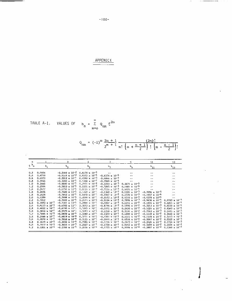
-1oo-
APPENDIX
.TABLE A-1. VALUES OF bn = Z Qm <Zm
m.~
Qm = (-1)”- 2m !~m+l
(m!m+ ~j ,)(. -+),
1.21.41.61.8
0.43730.39460.3465
0.4822 x0.3810 x0.3044 x0.2b66 x
0.12690.16700.20900.2474
.1 3 5 7 9 11 ,3
< b“ b, b3 h5 b7 b9 ’11 b13
0.2 0.4926 -0.2469 x 10⁻² 0.6178 x 10-50.4 0.4710
..
-0.9514 x 10-! 0,95145x 10⁻⁴ -0.637;-. 10-60.6 -0.2012 x 0,4560 L 10-3 -0.6866 x 10-50.8 -0.3283 x
..
0,,330 : U-2 -0.3569 x 10-61.0 -0.4600 x
..
0,2931 x 10⁻² -’).1?33x r3.387&x 10-50.2964 -0.5810 x
..
0,5371 x 10⁻² -0.3265 x O.lM1 x 10-~ --0.2417 -0.6794x
..
0.8616 ; W; -0.7156 x 0.44260.2026 -0.7&80 x
..
-0.1360 x 0.11010.1628 -0.18b2 x x 10-1 -0.2307 x 0.2370
2.0 0.1289 -0.7898 x
..
x 10-1 -0.3572 x 0,k5332.2 0.1012 -0.7693 x x 10-1 -0.5136 x 0.78862./, r),~agj, ,0-1 .0,,301 , 10-1 0,280, 10-1 -0.6907 x 0,12612.6 0.6153 x 10⁻¹ -0.6783 x 10⁻¹ 0.3043 ; 10:; -0.8796 , 0.18842.8 10-1 -0.6190 . m-l
10-1 -0.5573 . K-10.2650
3.03.2
, ,0-1 RR ‘ 0,3534,0-1 -0.4978 . ,0-1 . ,.-l .~.,~~g ~,~~~~
3.6 10-1 -0.4419x 10-13.6 ,.20*0 , ,0-1 .,),3.310x 10-1 0.3125
K 10-1 -0.1561 x 0.551110-1 -0.IW4 x 0.65,6
3.8 0.1679 x 10⁻¹ -0.3456z 10-1 0.2986 x 10⁻¹ -0.1716 x 0.74734.0 0.1412 x 10-~ -0.3055 x 10⁻¹ 0.2827 x 10⁻¹ -0.1758 x 0,83454.2 0.1201 x 10⁻¹ -0.2706 x 10⁻¹ 0.2656 x 10⁻¹ .0.1775 x 0.9106
0.32050.32830.32890.3231
x m-~x 10-3x 10⁻³. 10-3x 10⁻³. 10-2. 10-2x 10⁻². 10-2. 10-2x 10-2x 10-2x 10-2x 10-2. 10-1
-0.7096-0.1937-0.&578-0.9636-o.183&-0.3213-0.5224-0,7963-0.1149-0.1578-0.2067-0,2626-0,3,09-0,3807
x ,0-5x ,o-~x 10-~. 10-~, IO-3. 10-3. 10-3. 10-3x 10-2x 10-2x ,0-2x 10⁻²x ,0-2x 10⁻²
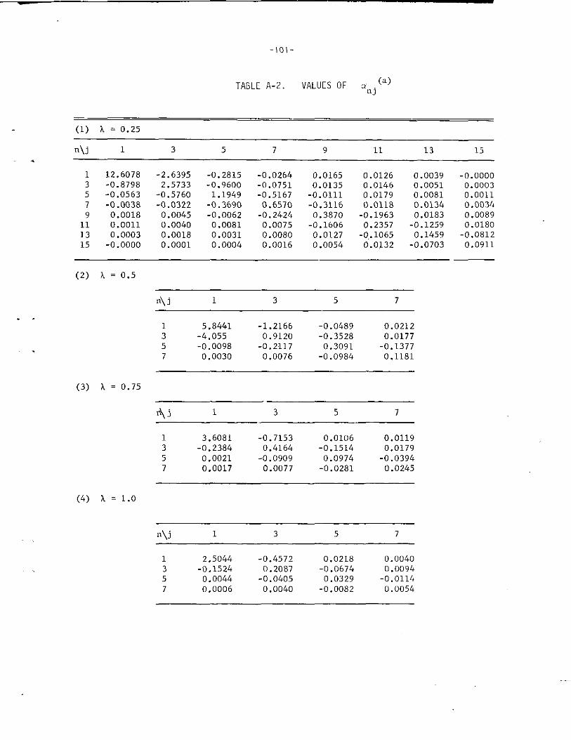
-1o1-
TABLE A-2. VALUES OF Onj (a)
(1) A = 0.25
n\j 1 3 5 7 9 11 13 15.
1 12.6078 -2.6395 -0.2815 -0.02643
0.0165 0.0126 0.0039 -0.0000-0.8798 2.5733 -0.9600 -0.0751 0.0135
50.0146 0.0051 0.0003
-0.0563 -O.576O 1.1949 -0.5167 -0.0111
70.0179
-0.00380.0081 0.0011
-0.0322 -0.3690 0.6570 -0.31169
0.01180.0018
0.01340.0045
0.0034-0.0062 -0.2424 0.3870 -0.1963
11 0.00110.0183
0.00400.0089
0.0081 0.0075 -0.160613
0.2357 -0.1259 0.01800.0003 0.0018 0.0031 0.0080 0.0127
15-0..1065 0.1459 -0.0812
-0.0000 0.0001 0.0004 0.0016 0.0054 0.0,132 -0.0703 0.0911
(2) a = 0.5
II\j 1 3 5 7
. .
(3) A = 0.75
1 5.8441 -1.2166 -0.0489 0.02123 -4.055 0.9120 -0.3528 0.01775 -0.0098 -0.2117 0.3091 -0.13777 0.0030 0.0076 -0.0984 0.1181
*j 1 3 5 7
1 3.6081 -0.7153 0.0106 0.01193 -0.2384 0.4164 -0.1514 0.01795 0.0021 -0.0909 0.0974 -0.03947 0.0017 0.0077 -0.0281 0.0245
(4) A = 1.0
n\j 1 3 5 7
1 2.5044 -0.4572 0.0218 0.00403 -0.1524 0.2087 -0.0674 0.00945 0.0044 -0.0405 0.03297
-0.01140.0006 0.0040 -0.0082 0.0054
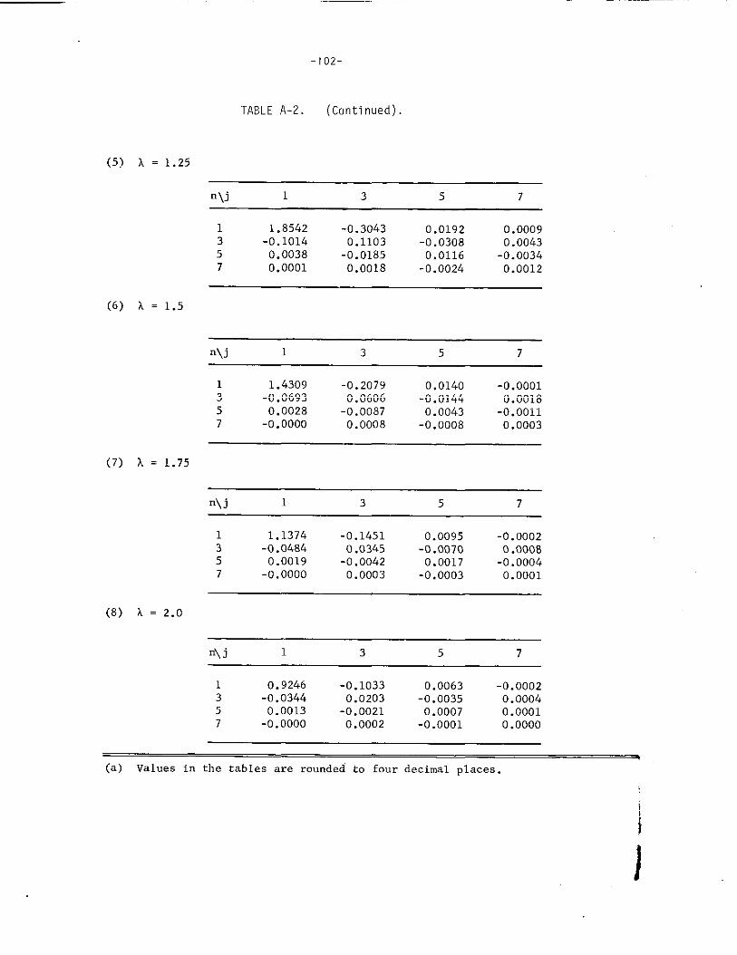
-1o2-
TABLE A-2. (Continued).
(5) k = 1.25
n \j 1 3 5 7
1 1.8542 -0.3043 0.0192 0.00093 -0.1014 0.1103 -0.03085
0.00430.0038 -0.0185 0.0116
7-0.0034
0.0001 0.0018 -0.0024 0.0012
(6) L = 1.5
n\j 1 3 5 7
(7) h = 1.75
(8) k = 2.o
1 1.4309 -0.2079 0.01403
-0.0001-0.0693 0.0606 -0.0144
50.0018
0.0028 -0.0087 0.00437
-0.0011-0.0000 0.0008 -0.0008 0.0003
n\j 1 3 5 7
1 1.1374 -0.1451 0.0095 -0.00023 -0.0484 0.0345 -0.0070 0.00085 0.0019 -0.0042 0.0017 -0.00047 -0.0000 0.0003 -0.0003 0.0001
n\j 1 3 5 7
1 0.9246 -0.1033 0.0063 -0.00023 -0.0344 0.0203 -0.0035 0.00045 0.0013 -0.0021 0.0007 0.00017 -0.0000 0.0002 -0.0001 0.0000
q(a) Values in the tables are rounded to four decimal places.
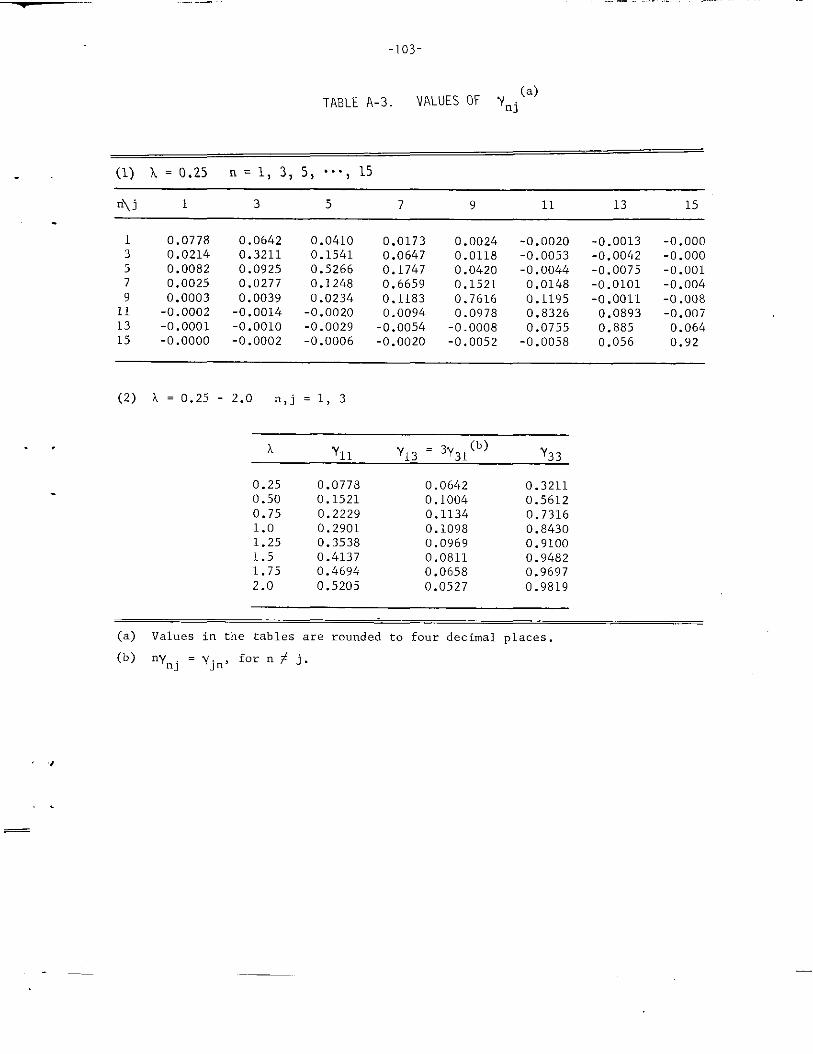
.
-1o3-
TABLE A-3 VALUES OF Ynj(a)
(1) A= O.25 n=l, 3, 5, . . . . 15
A j 1 3 5 7 9 11 13 15
1 0.07783 0.02145 0.00827 0.00259 0.0003
11 -0.000213 -0.000115 -0.0000
0.06420.32110.09250.02770.0039
-0.0014-0.0010-0.0002
0.04100.15410.52660.12480.0234-0.0020-0.0029-0.0006
0.0173 0.0024 -0.0020 -0.0013 -0.0000.0647 0.0118 -0.0053 -0.0042 -0.0000.1747 0.0420 -0.0044 -0.0075 -0.0010.6659 0.1521 0.0148 -0.01010.1183
-0.0040.7616 0.1195 -0.0011
0.0094-0.008
0.0978 0.8326 0.0893 -0.007-0.0054 -0.0008 0.0755 0.885 0.064-0.0020 -0.0052 -0.0058 0.056 0.92
(2) A = 0.25 - 2.0 n,j = 1, 3
A Y11 Y13 = 3Y31(b)
Y33
0.250.500.751.01.251.51.752.0
0.0778 0.06420.1521 0.10040.2229 0.11340.2901 0.10980.3538 0.09690.4137 0.08110.4694 0.06580.5205 0.0527
0.32110.56120.73160.843O0.91000.94820.96970.9819
(a) Values in the tables are rounded to four decimal places.
(b) nynj = yjn, for n # j.
,,
.
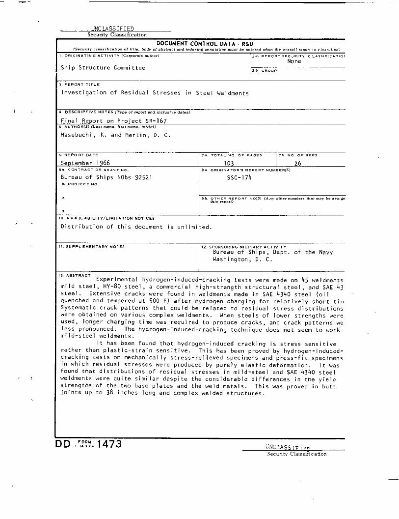
><
.,
U!4CMSSIFIEDSecurityClassification
DOCUMENT CONTROL OATA R&D[s..”,,0 .l... !!, IZI”.” 0! 1!1!.. bed, ofabstractand ,“.s.W e.notat$enm.., be ..,.?..when the.“.,.!(remrc IS.!.ss;l>...
, 0.,.,)4,,,.. .4CT I.ITY (Co,por. k ..,,.,, 2. REPORT SECURITY ,,.5s 1,,...10,
None
Ship Structure Committee 26 . .. ..
I
3. REPORT ,,...
Investigation of Residual Stresses in Steel weld~ents
4 DESCRIPTIVE .0,,, (T,,. .,,.,.,,... ......... ..,s.,
Final Report cm Proiect SR-]67, AU T. OR(S) (Lest !!.”!., ,,,s, ..”,., ,.,,,.,)
Masubuchi , K. and Martin, l). C
s.REPORT OAT. I7.. TOTAL NO OF ...s. 76 NO. OF .,.,
September 1966 103 26,.. CONTRACT0. . . . . . .0. 9. 0., .,..,0.., .,,0., .“... !?(s)
Bureau of Ships NObs 92521 SSC-174b.. . . . . . . .0.
d,
10. A“, lLA., L, T”/ L, MI TAT, oN NOTICES
Oistributio” of this docwnent is unlimited.
1!. 51JP, LEMENTA17Y NOTES ,2.S.PONSOR, NG M,L,TAR, AC T, V,,’Y
Bureau of Ships, Oept. of the NavyWashington, O. C.
I
‘3 ‘e’TRAc’ Experimental hydrogen- induced-cracking tests were made on 45 weldmentsmild steel, HY-80 steel, a commercial high-strength structural steel, a“d SAE 43steel. Extensive cracks were found in weldments made in SAE 4340 steel (oilquenched and tempered at 500 F) after hydrogen charging for relatively short tirnSystematic crack patterns that could be related to residual stress distributionswere obtained on various complex weldments. When steels of lower strengths wereused, longer chai-gi”g time was requi red to produ’e ‘ra’ks , and ‘rack pattei-”s weless pronounced. The hydrogen-induced-cra’king technique does “ot seem to workmild-steel weldments.
It has bee” found that hydrogen-induced cracking is stress sensitiverather than plastic-strain sensitive, This has been proved by hydrogen-induced-cracking tests on mechanically stress -rel Ieved specimens and press-fit specimensin which residual stresses were produced by purely elastic deformation. It wasfound that distributions of residual stresses in mild-steel and SAE 4340 steelweldments were quite similar despite the considerable differences in the yieldstrengths of the two base plates and the weld metals. This was proved in buttjoints up to 38 inches long and complex welded structures.
)D ,;::% 1473 LINC~SSIFTFnSecurity Classification
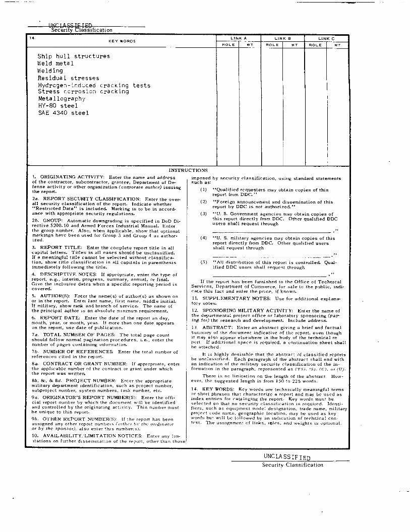
Ship hull structuresWeld metalWeldtngResidual stressesHydrogen -ir,d:ceti cracking testsStress ccrrosion crackingMetallographyHY-80 steelSAE 4340 steel
INSTRUCTIONS
1. 0Rli3NATING ACTIVITY Enter the .ame ..d .ddreSS,f the contr act.,, subcontractor, want,,, Department of Defense activity or other organization (coqorate .Ulho.)issuinslhe ,epo,t,
2., REPORT sECUEfTY CL ASS1F1CATIOIN Enterthe ......11security.I.ssific.tionof the report.Indicate whether!{ Restricted Datar, is included. Marking is t. be i. accord-ante with appropriate security regulations.
2b.GROUP: Au(om aticdowngrading i. specifiedin DoD Di-
.ecti”e 5200. 10 and Armed Forces Industrial Manual. Enter:he group mumber, Also, when applicable, show that optionalmarkings h,,. bee” used for Grou P 3 and Group 4 as author.ized.
3. REPORT TITLE Enter the complete .ewrl title in all
:apital letters. Titles in all cases should be unclassified.[f e meaningful title cannot be selected without .I.ssifica.ion, show title cla,, ificeti. n in .11 caPitals in pa,en, hesis
,mrnediately following the title,
L DESCRIPTIVE NOTES If .Pprapriate, ,“,., the ,Pe ofeport, e. g., interim, progress, summary, . . ...1. or fi.al.>i. e the inclusive dates when a specific reporting period is,o. ered,
i. AUTHOR(S> Enter the name(s) of author(s) as shown c,.,, in the ,q, ar,, Enter last name, firs, .,,, ),,middle initial.f military, show r.di a..i branch of service, The name ofhe ~rinc ipal author is . . absolute minimum requirement.
i REPORT DATE Enter the da,, of the ,,LIc,,, as day,month, yew ., month, Y,.,, If ,“.,, then one date appear,>“ the rq, ort, .,. d.,. of public .,,..,
7a. TOTAL NUMBER OF PAGES The ,.,.1 page count;ho.ld follow nom.] pagination procedures, L.,, enter the,utnber of pages containing ,“forrnatiom
7b.NUMBER OF REFERENCE% En,,, the ,0,.1 number ofefere”ces cited in the ,ePor,.
<a. CONTRACT OR GRANT NUMBER: If aDwoPr,.3te, enterhe .p~licrdble “umber of the <..,,,., 0, want under whichhe rqm. t was written
3b,k, & 8d.pROJECT NuMBER Enter the appropriate.ilitary department identific.tiom, such as project number,;.bc.rejectnumber, sys!em numbers, task number, etc.
la. OR IGINATOR>S REPORT NUMEER(S): En,,, the of fi.,id report “umber by tihich the document will be iden,,f, ed,r, d controlled by the ori,, nat, nc act,. ,,,. This numb,., n,. ,,,. unique,0 (his report,
2b. OTHER REPORT N“!.!BER( S): 1[the ,,..” has b,,.,Ssig”.d ... other rep.,,num.b,r, (,,(,,,,,,.,,, or;g,n.tor,.by <he sponsor),.,s. ,.,., th). “umber(,).
10,AVAIL ABILITY, LIMLTATtOX KOTICF.5 Enter ... Mm.iietions.. fwtbec d,.semi. ation .( the rtport,other than those
-WT
-.0, .
-,0,,
—
—
. .
—
imposed by security classification, using standard s,a,etnentssuch as
(1)
(2)
(3)
(4)
(5)
“Qualified requesters may obtain copies of thisreport from DDC,,
,. Foreign .nnou..,~..t end dissemination of ,his
report by DDC i, not authorized ,>
‘,”, S, Gov,..m.”t agencies may obtain copies of
this report directly from DDC, Other qualified DDC.s,.s shall request through
,,,
“U. S. military .Eenries may obtei” copies of this.rqort directly from DDC Other qu.lified usersshall request throu~h
,,!
.’A,l ~,,~ri~u,lo” .f this rq,o,, is controlled. @d-
ified DDC users shsll request through
,,
11 the report has been furnished to the Office of TechnicalServices, Department of Conm,,erce, for sale to the public, indi.cat, this fact and enter the p,,.., if kn. v,m
11. SUPPLEMENTARY NOTES Use f“r additional expla”..tory motes.
12. SPONSORING MILITARY ACTIVITY Enter the name ofthe dq. rttne”v.l project office o. laboratory sponsoring (par;n~ for) the research and developme”,. l“clude add,,.,
13 ABSTRACT: Enter an abstract giving . brief and factual
sum,”. ry “f the document indicative of the rqort, even th.ugh,, m.y .1s” aPDe. r el, e.,,he,e in the body of the ,echoical ,..
P’Jet. If eddit$on=l space is rewired, a co. tin. ation sheet shallbe attached.
It is highly de, irat,le thet the abstract .[ classified reports
be .nclass. fied. Each Darasr. ph of the abstract shall e“d withen indication of the mili@w security .Iass, ficat, o,, of the ,n.l“,, ”.,,.. in the psr. graph, r,prescntt. d ., (,.s,, c.,, <.>, 0, (v>.
There $s no limitation on the length of the abstract. How...,,, the suggested Iemg,il ,s from 150 ,, 225 words.
14. KEY WORDS: Key words .re technically meaningful termsor short phrases that cha, ac, er,ze e ,...,, a“d ma. be used ,,.mdex entries for ceta)ogi”g the report.’ Key word; must beselected S. that . . security .I. ssif)catiom .s required. Ide. ti.lie,,, ,u.h as .qu,p me,,, model ales, ~at, on, trade name, i“ilit. ?
P,.J.c1 c“de “am., wowaph,c local,””, may be used as keywords b., will b. followed F,y ,. ,n’i, ca, io. of t,, hn, cal .0..,,,,. T%, .,,,. ”,”.., of ,,nks, ,01, s, and weigh,. ,s 0,,, ”,,,1.
UNCLASSIFIED
Securitv Classification
NATIONAL ACAOEMY OF SCIENCES-NATIONAL RESEARCH COUNCIL
oIVISION OF ENGINEERING
The Ship Hul1 Research Committee undertakes research service activities in the generalfields of materials, design, and fabrication, as relating to improved ship hull structure, whensuch activities are accepted by the Academy as part of its functions. The Committee recommendsresearch objectives and projects; provides liaison and technical guidance to such studies; re-views project reports; and stimulates productive avenues of research.
SHIP HULL RESEARCH COMMITTEE
7
Chairman:
Vice-Chairman:
Mr. Maurice L. SellersNewport News Shipbuildingand Dry Dock Company
Or. H. Norman AbramsonOirector, Oept. of MechanicalSciencesSouthwest Research Institute
Mr. Harold G. AckerShipbuilding OivisionBethlehem Steel Corp.
Mr. Alvin E. CoxAssistant Naval ArchitectNewport News Shipbuildingand Ory Oock Company
Mr. Robert Oippy, Jr.Structural Oesign EngineerSun Shipbuilding & OryDock Company
Dr. N. H. JasperTechnical OirectorU. S. Navy Mine OefenseLaboratory
Mr. F. J. JoyceManager Marine DesignNational Bulk Carriers, Inc.
Mr. T. M. BuermannGibbs & Cox, Inc.
Vice-Chairman:
Or. J. M. FranklandRetiredNational Bureau of Standards
BMr. William R. JensenStructural Methods EngineerGrunrnanAircraft EngineeringCorporation
Mr. J. A. KiesHead, Ballistics BranchMechanics OivisionNaval Research Laboratory
Or. William R. OsgoodSchool of Engineering andArchitectureCatholic University of Pmerica
Or. G. M. SinclairResearch Professor of Theoreticaland Applied MechanicsUniversity of Illinois
Mr. Merville WillisNaval ArchitectNew York ShipbuildingCorporation
Professor Raymond A. ‘?qleDept. of Naval Arcrtitect2reMarine EngineeringUniversity of ?5c.-iga-
Arthur R. Lytle
Technical Oirector
SHIP STRUCTURE COMMITTEE PUBLICATIONS
These documents are distributed by the Clearinghouse, Springfield,Va. 22151. These documents have been announced in the TechnicalAbstract Bulletin (TAB) of the Defense Documentation Center (OOC),Cameron Station, Alexandria, Va. 22314, under the indicated ADnumbers. There is no charge for documents for registered usersthe DDC services. Other users must pay the prescribed rate setthe Clearinghouse.
ofby
Index of Ship Structure ConnrritteeFub Zications (1946 -April 1965)
SSC-163, Investigation of Bending Moments within the Midship Half Length ofa Mariner Model in Extreme Waves b.yN. M. Maniar. June 1964.
SSC-164,
SSC-165,
SSC-166,
SSC-167,
SSC-168,
SSC-169,
SSC-170,
SSC-171 ,
SSC-172,
AD 605345
Results from Full-Scale Measurements of Midship Bending Stresseson Tuo C4-S-B5 D~y-Cargo Ships Operating in North Atlantic Serviceby D. J. Fritch, F. C. Bailey and N. S. Wise. September 1964,AD 605535
Local Yielding and Extension of a Crack Under PZane StreG. T. Hahn and A. R. Rosenfield. December 1964. AO 610??$by
Reversed-Bend Tests of ABS-C Steel with As-Rolled and MachinedSurfaces by K. Satoh and C. Mylonas. April 1965. AD 460575
Restoration of Ductility of Hot or Cold Strained ABS-B Steel byTreatment at 700 to 1150 F by C. Mylonas and R. J. Beaulieu.April 1965. AD 461705
Rolling History in Relation to the Toughness of Ship Plate byf,B. M. Kapadia and W. A. Backofen. May 1965. AO 465025 ,’
%
InterpretativeReport on Weld-Metal Toughness by K. Masubuchi,R. E. Monroe and D. C. Martin. July 1965. AD 466805
Studies of Some Brittle Fracture Concepts by R. N. Wright, W. J.Hall, S. W. Terry, W. J. Nordell and G. R. Erhard. September 1965.AD 476684
Micro-and Macroerack Formation by B. L. Averbach. October 1965.AD 473496
Crack Extension and Propagation Under Plane Stress by A. R.Rosenfield, P. K. Dai and G. T. Hahn. March 1966. AD 480619

![Prediction of welding residual stresses using machine ... · characterise the distribution of residual stresses in structural welds [6, 7]. With the development of residual stress](https://img.pdfslide.us/doc/110x75/5fa3f63f3be93a3412525cc3/prediction-of-welding-residual-stresses-using-machine-characterise-the-distribution.jpg)