Embed Size (px)
Citation preview
Residual Stresses in Hollow Section Joint
Czech Technical University in Prague
Faculty of Civil Engineering
Department of steel and timber structures
Erasmus Mundus: SUSCOS 2016-18
Author: Kovil Chaitanya Reddy R A
Supervisor: prof. Ing. František Wald, CSc.
Czech Technical University in Prague
Department of Steel and Timber Structures
European Erasmus Mundus Master
Sustainable Constructions under natural hazards and catastrophic events
520121-1-2011-1-CZ-ERA MUNDUS-EMMC
3
Declaration
I hereby declare that this assignment is my own work and is not copied from any other person's
work (published or unpublished), and has not previously submitted for assessment either at Czech
Technical University in Prague or elsewhere and I have stated all information resources used in
conformity with the Methodical guide for ethical development of university final thesis.
Prague, 7 January 2018 R A Kovil Chaitanya Reddy

European Erasmus Mundus Master
Sustainable Constructions under natural hazards and catastrophic events
520121-1-2011-1-CZ-ERA MUNDUS-EMMC
4
Acknowledgements
I would like to express my sincere gratitude to my supervisor František Wald for his excellent
guidance throughout this period. I couldn’t have finished this thesis without his constant support
and motivation. His valuable inputs, contributions, patience and encouragement have helped me
complete my work and I am highly indebted to him.
I thank the Board of directors of the SUSCOS consortium for giving me this wonderful opportunity
to pursue this degree and all my teachers for the knowledge they have shared during my time in
SUSCOS.
I would like to thank Svitlana Kalmykova for providing the mechanical test results which were
used for validation of the model used in this thesis.
In special, I would like to thank the Michal Jandera for contributing to this thesis with his great
knowledge and time by the several discussions about the subject. I am grateful to him for his
support and time.
I am grateful to my colleagues and friends for having faith in me and encouraging me to pursue
my dreams. This journey would not have been the same without them.
Lastly, I would like to dedicate this thesis to my father, mother and brother, who have showered
me with their unconditional love, support and encouragement. They are the reason for who I am
today, and I look forward to fulfilling their wishes to the best of my ability.
European Erasmus Mundus Master
Sustainable Constructions under natural hazards and catastrophic events
520121-1-2011-1-CZ-ERA MUNDUS-EMMC
5
Abstract
This dissertation presents a study involving the influence of Residual stresses on a hollow section
T-Joint subjected to compressive axial load on the brace.
Nowadays, it is only possible to perform analytical solutions regarding this joint resistance
capacity based on empirical formulas which are included on EC 1993-1-8.
The present study explores the development of numerical and analytical models to further
understand the behavior of T-joint under residual stresses. The numerical model is built on FE
software ABAQUS and is validated and verified with the experimental data. Residual stresses are
applied in the Numerical model using solid and shell elements as presented in this thesis.
A Sensitivity study was carried out and included in this study to evaluate the influence of residual
stresses on the resistance of the compressed joint. The comparison between numerical models of
different elements highlights the effectiveness and degree of accuracy of the studied finite element
models.
Thus, by concluding with all information and results achieved, it is intended to carry out a study
on the Influence of Residual stresses to design of hollow section T-joints which can be used by
civil engineers with more reliability and accuracy.
Keywords:
Steel structures, Hollow section Joint, Validation and verification, Residual Stresses
European Erasmus Mundus Master
Sustainable Constructions under natural hazards and catastrophic events
520121-1-2011-1-CZ-ERA MUNDUS-EMMC
6
Table of Contents
1. Introduction ............................................................................................................................ 8
1.1 Hollow Sections and their Joints ...................................................................................... 8
1.2 Residual stresses ............................................................................................................... 8
2. State of Art ............................................................................................................................. 9
2.1 Research on Hollow Section Joints .................................................................................. 9
2.1.1 Types of Joints ......................................................................................................... 10
2.1.2 Design Rules ............................................................................................................ 11
2.1.3 Failure Modes .......................................................................................................... 13
2.1.4 Welded T Joint between RHS members .................................................................. 15
2.1.5 Design resistances of Welded Joints between RHS brace and RHS chord ............. 16
2.2 Residual Stresses ............................................................................................................ 19
2.2.1 General ..................................................................................................................... 19
2.2.2 Measurement Techniques ........................................................................................ 20
2.2.3 Influence on Hollow Section Joints ......................................................................... 21
2.3. Hollow Cold Formed Sections ...................................................................................... 23
2.3.1 Production ................................................................................................................ 23
2.3.2 Welding ................................................................................................................... 27
2.4 Mechanical Tests ............................................................................................................ 28
2.4.1 Specimen design ...................................................................................................... 28
2.4.2 Test procedure ......................................................................................................... 30
2.4.3 Measurement plan .................................................................................................... 31
3. Objectives ............................................................................................................................ 32
4. FEA Model .......................................................................................................................... 33
4.1 Mechanical model .......................................................................................................... 33
4.2 Model Without Residual Stresses .................................................................................. 35
4.2.1 Limit Deformation ................................................................................................... 36
4.2.2. Maximum strain ...................................................................................................... 36
European Erasmus Mundus Master
Sustainable Constructions under natural hazards and catastrophic events
520121-1-2011-1-CZ-ERA MUNDUS-EMMC
7
4.2.3. Type of structural analysis ...................................................................................... 37
4.2.4. Material properties .................................................................................................. 38
4.2.5. Mesh ....................................................................................................................... 39
4.2.6. Support and load conditions ................................................................................... 40
4.3 Validation ....................................................................................................................... 42
4.4 Verification..................................................................................................................... 43
5. Sensitivity Study .................................................................................................................. 44
5.1 Application of Residual Stresses on the model .............................................................. 44
5.2 Results and Discussions ................................................................................................. 46
6. Summary .............................................................................................................................. 51
6.1 Conclusions .................................................................................................................... 51
6.2 Future Developments ..................................................................................................... 52
References ................................................................................................................................ 53
European Erasmus Mundus Master
Sustainable Constructions under natural hazards and catastrophic events
520121-1-2011-1-CZ-ERA MUNDUS-EMMC
8
1. Introduction
1.1 Hollow Sections and their Joints A hollow section is a section made up of steel profile having tubular cross section. Hollow sections
are available in circular, rectangular, square and elliptical shapes. These hollow sections have same
radius of gyration in all directions making it an efficient section. Hollow sections are mostly used
in plane and space trusses as they are efficient in compression. Many examples in nature
demonstrate the excellent properties of the hollow section as a structural element in resisting
compression, tension, bending and torsion forces [4].
According to Eurocode 1993-1-8, Joint is a Zone where two or more members are interconnected.
For design purposes it is the assembly of all the basic components required to represent the
behaviour during the transfer of the relevant internal forces and moments between the connected
members. Normally, Joints in steel structures are usually made by Bolting or welding. Bolting is
the most commonly used technique as it is simple and economical. However, welding is deemed
in hollow section joints due to its efficiency and aestheticism. Welding has made the connection
between the hollow sections easier and resulted in widespread of hollow sections.
European standard EN 1993-1-8, Chapter 7 gives detailed application rules to determine the static
resistances of uni-planar and multi-planar joints in lattice structures composed of circular, square
or rectangular hollow sections, and of uni-planar joints in lattice structures composed of
combinations of hollow sections with open sections [3].
1.2 Residual stresses Residual stresses are the internal stresses that are remained in an element even after the removal
of external loading applied during manufacturing process. Residual stresses were defined in [5] as
“locked-in stresses that exist in a body or a part of a body in the absence of any externally applied
load”. Steel members are subjected to high temperatures during fabrication by rolling or welding.
Cooling of these members always takes place unevenly. Due to this uneven heating and cooling,
Structural members contain these residual stresses. Residual stresses are the consequence of
several steps in the production of welded structures (manufacturing effects), e.g. the cutting
process, the welding process, the assembly process and the cleaning peening [6]. Although it is
possible to remove or reduce residual stresses by some mechanical process, it is not recommended
in structural engineering applications due to economic reasons.
European Erasmus Mundus Master
Sustainable Constructions under natural hazards and catastrophic events
520121-1-2011-1-CZ-ERA MUNDUS-EMMC
9
2. State of Art
2.1 Research on Hollow Section Joints An extensive research has been performed on the hollow section joints since the evolution of the
hollow sections. Hollow sections are being extensively used in structural applications due to their
efficiency in resisting compression. However, connecting those hollow sections is important to
satisfy the structural needs. Hollow section joint is possible only through welding. The most
common welded connections are axially loaded truss type members forming joints in a T, Y or K
configurations.
Many design guidelines have been published to design of welded hollow section connections based
upon the theoretical and experimental research carried out. First design recommendations for
hollow section connections were published forty years ago by International Institute of Welding.
Later these recommendations were adopted by many countries around the world. These
recommendations have also been included in Eurocode 3.
CIDECT has done an extensive research in the field of hollow section joints. The results of the
investigations have been incorporated and updated into the many national and international design
recommendations. In 1982, Wardenier [4] published a book “Hollow section joints” in order to
establish certain parameters in the design of hollow section joints. The research projects on these
joints are still carried out by CIDECT.
Currently in Europe, Design of hollow section joints should be done in accordance with [3] [EN
1993-1-8], Chapter 7: Hollow section joints and CIDECT Design guide for structural hollow
sections in mechanical applications.
European Erasmus Mundus Master
Sustainable Constructions under natural hazards and catastrophic events
520121-1-2011-1-CZ-ERA MUNDUS-EMMC
10
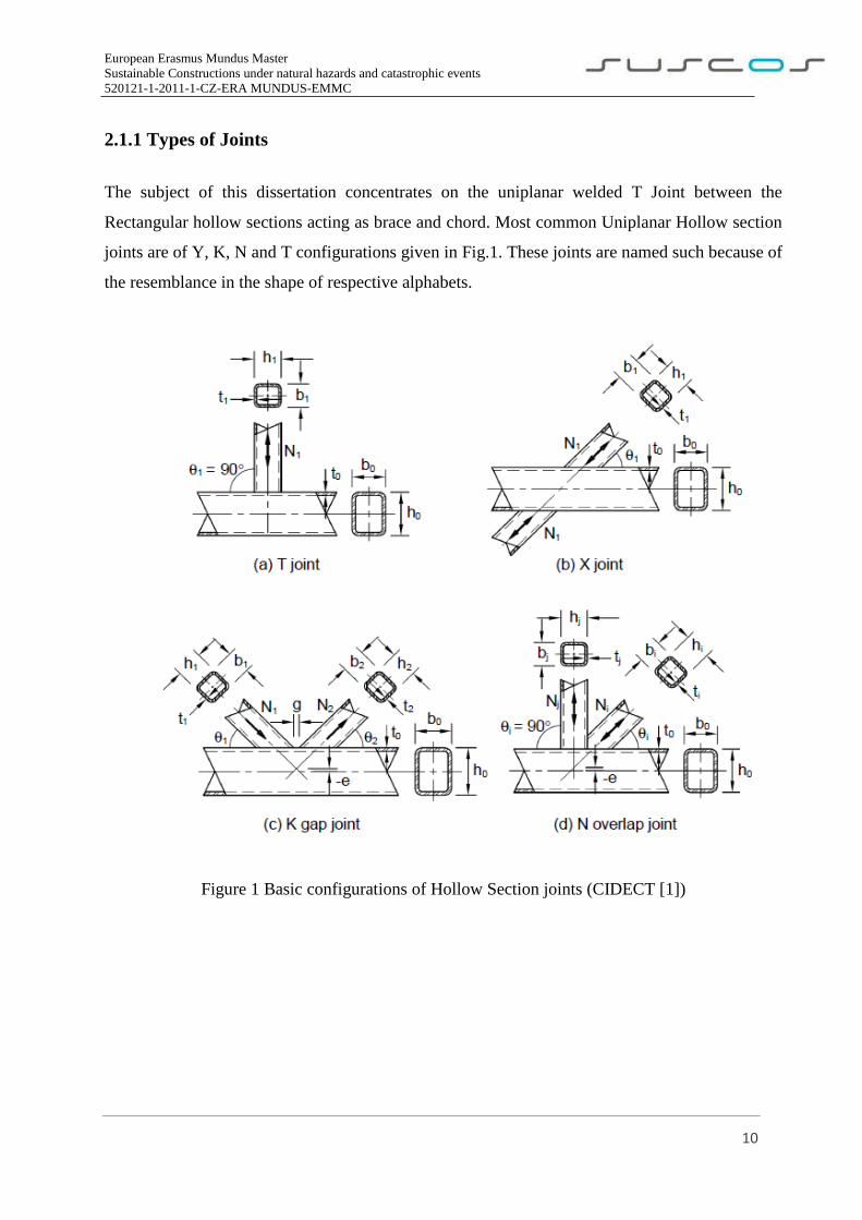
2.1.1 Types of Joints
The subject of this dissertation concentrates on the uniplanar welded T Joint between the
Rectangular hollow sections acting as brace and chord. Most common Uniplanar Hollow section
joints are of Y, K, N and T configurations given in Fig.1. These joints are named such because of
the resemblance in the shape of respective alphabets.
Figure 1 Basic configurations of Hollow Section joints (CIDECT [1])

European Erasmus Mundus Master
Sustainable Constructions under natural hazards and catastrophic events
520121-1-2011-1-CZ-ERA MUNDUS-EMMC
11
2.1.2 Design Rules
Eurocode 1993-1-8:2017 [3] specifies that, “For hot finished hollow sections and cold formed
hollow sections the nominal yield strength of the end product should not exceed 460 N/mm2. For
end products with a nominal yield strength higher than 355 N/mm2, the static design resistances
given in this section should be reduced by a factor 0,9”.
EN 1993-1-8:2017 [3], CIDECT [1] and IIW also states that the nominal wall thickness for any
hollow section should not be less than 2.5 mm. Maximum wall thickness should not exceed 25mm
unless special measures have been taken to ensure the adequacy of the thickness properties of the
material [3].
CIDECT design guide [1] suggests that, for any formula used for computing design resistance, the
yield stress should not be considered more than 0.8 times to the nominal ultimate strength.
CIDECT [1] exclusively points out that wall thickness for RHS sections should not be more than
25mm. CIDECT [1] states that the angle between Rectangular hollow sections at the joint should
at least be > 30°.
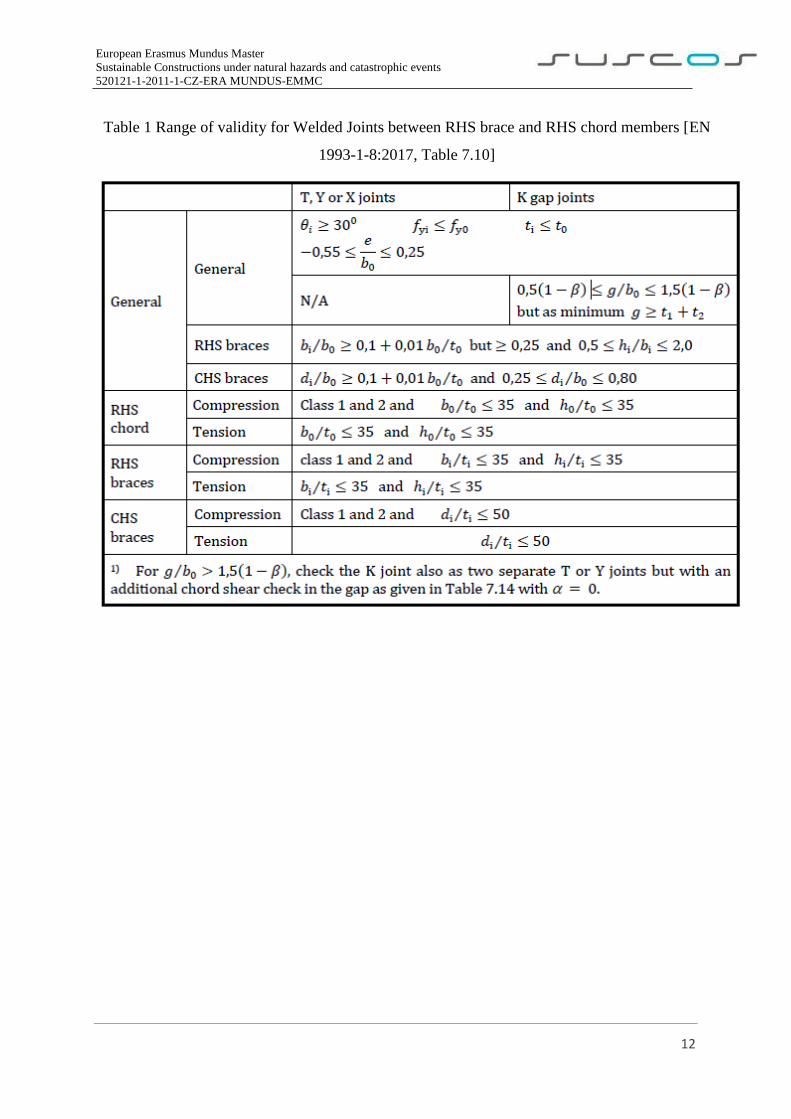
EN 1993-1-8:2017 [3] gives range of validity (Table 1) for welded joints between CHS or RHS
brace members and RHS chord members.
European Erasmus Mundus Master
Sustainable Constructions under natural hazards and catastrophic events
520121-1-2011-1-CZ-ERA MUNDUS-EMMC
12
Table 1 Range of validity for Welded Joints between RHS brace and RHS chord members [EN
1993-1-8:2017, Table 7.10]
European Erasmus Mundus Master
Sustainable Constructions under natural hazards and catastrophic events
520121-1-2011-1-CZ-ERA MUNDUS-EMMC
13
2.1.3 Failure Modes
The most economical and common way to connect rectangular hollow sections is by direct
connection without any intersecting plates or gussets [7]. The general modes of failures given in
Fig.2 and their design rules have been classified based on the numerical and experimental studies
of those joints. Modes of failure for RHS have been classified by Wardinier [4] in 1982. Later they
were indicted into EN 1993-1-8, CIDECT [1] and many international design rules. Depending on
the type of joint, the joint parameters and the loading conditions several types of failure can occur
[4].
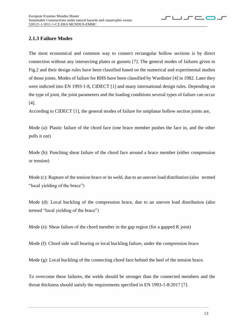
According to CIDECT [1], the general modes of failure for uniplanar hollow section joints are,
Mode (a): Plastic failure of the chord face (one brace member pushes the face in, and the other
pulls it out)
Mode (b): Punching shear failure of the chord face around a brace member (either compression
or tension)
Mode (c): Rupture of the tension brace or its weld, due to an uneven load distribution (also termed
“local yielding of the brace”)
Mode (d): Local buckling of the compression brace, due to an uneven load distribution (also
termed “local yielding of the brace”)
Mode (e): Shear failure of the chord member in the gap region (for a gapped K joint)
Mode (f): Chord side wall bearing or local buckling failure, under the compression brace
Mode (g): Local buckling of the connecting chord face behind the heel of the tension brace.
To overcome these failures, the welds should be stronger than the connected members and the
throat thickness should satisfy the requirements specified in EN 1993-1-8:2017 [7].
European Erasmus Mundus Master
Sustainable Constructions under natural hazards and catastrophic events
520121-1-2011-1-CZ-ERA MUNDUS-EMMC
14
Figure 2 General Modes of failure [1]
European Erasmus Mundus Master
Sustainable Constructions under natural hazards and catastrophic events
520121-1-2011-1-CZ-ERA MUNDUS-EMMC
15
2.1.4 Welded T Joint between RHS members
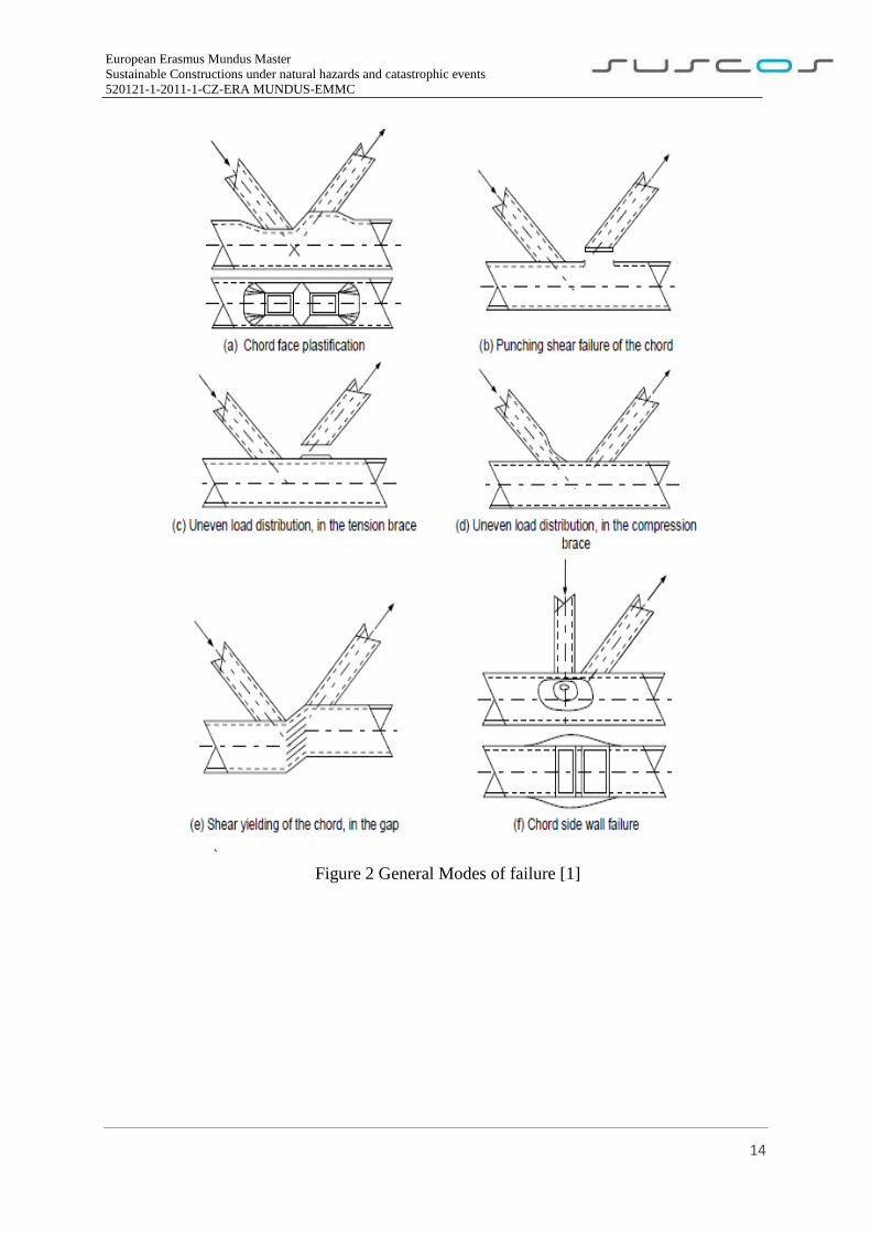
The geometry adopted in this study is a T- Joint “where the horizontal element is the chord, to
which the vertical element, the brace, is fully welded. The geometry of a joint is generally defined
by the dimensions given in Fig.3 and by the joint parameters α,,, and g’ [7]. In T joint, both the
members are connected exactly perpendicular to each other otherwise it is considered as Y Joint.
The most common type of joint in hollow sections is the fully welded joint, that is quite simple
and aesthetically appealing. One of the reasons for the popularity of this solution is the
cumbersome access to the inside of the column, making bolted solutions more complex and costly
[12].
Figure 3 Welded T Joint between RHS brace and RHS Chord
European Erasmus Mundus Master
Sustainable Constructions under natural hazards and catastrophic events
520121-1-2011-1-CZ-ERA MUNDUS-EMMC
16
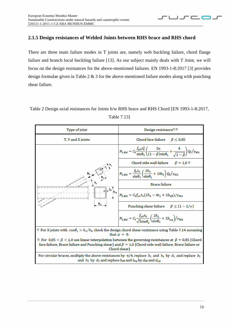
2.1.5 Design resistances of Welded Joints between RHS brace and RHS chord
There are three main failure modes in T joints are, namely web buckling failure, chord flange
failure and branch local buckling failure [13]. As our subject mainly deals with T Joint, we will
focus on the design resistances for the above-mentioned failures. EN 1993-1-8:2017 [3] provides
design formulae given in Table 2 & 3 for the above-mentioned failure modes along with punching
shear failure.
Table 2 Design axial resistances for Joints b/w RHS brace and RHS Chord [EN 1993-1-8:2017,
Table 7.13]
European Erasmus Mundus Master
Sustainable Constructions under natural hazards and catastrophic events
520121-1-2011-1-CZ-ERA MUNDUS-EMMC
17
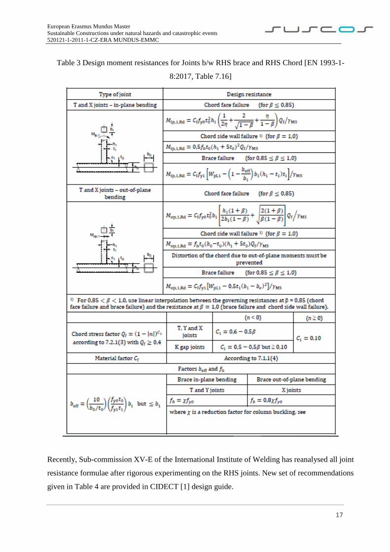
Table 3 Design moment resistances for Joints b/w RHS brace and RHS Chord [EN 1993-1-
8:2017, Table 7.16]
Recently, Sub-commission XV-E of the International Institute of Welding has reanalysed all joint
resistance formulae after rigorous experimenting on the RHS joints. New set of recommendations
given in Table 4 are provided in CIDECT [1] design guide.
European Erasmus Mundus Master
Sustainable Constructions under natural hazards and catastrophic events
520121-1-2011-1-CZ-ERA MUNDUS-EMMC
18
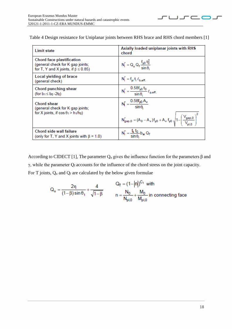
Table 4 Design resistance for Uniplanar joints between RHS brace and RHS chord members [1]
According to CIDECT [1], The parameter Qu gives the influence function for the parameters β and
γ, while the parameter Qf accounts for the influence of the chord stress on the joint capacity.
For T joints, Qu and Qf are calculated by the below given formulae
European Erasmus Mundus Master
Sustainable Constructions under natural hazards and catastrophic events
520121-1-2011-1-CZ-ERA MUNDUS-EMMC
19
2.2 Residual Stresses
2.2.1 General
Residual stress is defined as the stress present inside a component or structure after all applied
forces have been removed [14]. Residual stresses can be tensile or compressive depending up on
the location and type of non-uniform volumetric change taking place due to differential heating
and cooling like in welding and heat treatment or localized stresses like in contour rolling,
machining and shot peening etc.
According to [14], Residual stresses can be categorized into three types, they are
Type 1: Macro-stresses occurring over a large span that involve many grains within a material.
Type 2: Micro-stresses caused by differences in the microstructure of a material.
Type 3: Exist inside a grain because of crystal imperfections within the grain.
Residual stresses can have a significant effect on the fatigue strength of welded joints and
components. Fatigue strength can be increased by compressive residual stresses and can be
decreased by tensile residual stresses [6]. Residual stresses, which arise in the welded joints are a
consequence of strains caused by solidification, phase change and contraction during welding, also
affect the fatigue behavior of welds [9].
Some general effects of Residual Stresses are,
Low cycle and high cycle fatigue performance
Distortion
Peen forming
Fretting
Stress corrosion cracking and hydrogen initiated cracking
Crack initiation and propagation
Presence of residual stresses in the weld joints can encourage or discourage failures due to external
loading as their effect is additive in nature. Residual stress can raise or lower the mean stress
experienced over a fatigue cycle [14]. It means that mean stress must be controlled properly
European Erasmus Mundus Master
Sustainable Constructions under natural hazards and catastrophic events
520121-1-2011-1-CZ-ERA MUNDUS-EMMC
20
according to the type of residual stresses (Compressive or Tensile) to keep the joint unaffected.
For this to happen, one need to have a knowledge on measurement of residual stresses.
2.2.2 Measurement Techniques
Measurement of residual stresses is important to evaluate the real behavior of joint. Real data is
necessary to improve the accuracy and effectiveness of the finite element modelling. Many
measurements of the residual stresses in tubular joints due to the welding process were undertaken
by researchers at Cambridge University in the eighties.
For the prediction of the residual stresses and distortions attributed to welding, previous
investigations have developed several experimental methods, including stress relaxation, X-Ray
diffraction, ultrasonic and cracking [15]. There are many methods of residual stress measurements
with varying levels of sophistication and complexity. One of the most simple but effective
techniques involves using semi-destructive techniques such as the conventional hole drilling
technique and ring-core method [9].
Hole drilling method is based on the stress relaxation induced by the drilling of a small hole:
generally, 1-5 mm in diameter and a depth approximately equal to its diameter. Strain-gauge
rosettes, glued around the hole before drilling, measure the relieved surface strains. Thus, from
these relieved strains, it is possible to calculate the residual stress field present in the material
before the hole was drilled [10].
Need for Residual Stress measurements,
Failures that are suspected as being caused by fatigue, stress corrosion, corrosion fatigue, or
hydrogen embrittlement
Assessment for the continued serviceability of a component
Distortion occurring during processing of a component
Distortion of components during storage or in service
European Erasmus Mundus Master
Sustainable Constructions under natural hazards and catastrophic events
520121-1-2011-1-CZ-ERA MUNDUS-EMMC
21
2.2.3 Influence on Hollow Section Joints
According to [6], For the study of influence of residual stresses, it is important to know about the
factors that influence magnitude and distribution of these stresses. The magnitude and distribution
of residual stresses after the finishing of the complete manufacture of the welded structure depend
on the material, shape and dimension of the welded structure, the welding process, etc.
Residual stresses, which arise in the welded joints because of strains caused by solidification,
phase change and contraction during welding, also affect the fatigue behavior of welds. Tensile
residual stress of yield magnitude may exist in as-welded structures and may cause detrimental
effects to the fatigue behavior of welded structures [9].
In general, compressive residual stress in the surface of a component is beneficial. It tends to
increase fatigue strength and fatigue life, slow crack propagation, and increase resistance to
environmentally assisted cracking such as stress corrosion cracking and hydrogen induced
cracking. Tensile residual stress in the surface of the component is generally undesirable as it
decreases fatigue strength and fatigue life, increases crack propagation and lowers resistance to
environmentally assisted cracking.
The above stresses generated in Welded T joint can act in two directions namely transversal and
longitudinal to the weld. A stress acting normal to the direction of the weld bead are known as
transversal stresses and those acting parallel are known as longitudinal stresses [15].
One of the major conclusions of the research carried out at Cambridge University was that the
mean longitudinal stresses (stresses parallel to the weld direction) obtained by sectioning never
exceeded the material yield stress, fy, by more than 20 N/mm2. Furthermore, mean transverse
residual stresses were never seen to exceed ~0.65·fy. In general, it is the transverse stress
distribution that is of the most interest, as the principal stresses due to the applied loads also tend
to be oriented perpendicularly (or transversely) to the weld direction [10].
European Erasmus Mundus Master
Sustainable Constructions under natural hazards and catastrophic events
520121-1-2011-1-CZ-ERA MUNDUS-EMMC
22
This subject mainly deals with the T joint weld between RHS brace and RHS chord. So, it is
important to realize the behaviour of these stresses in this joint. As concluded in [15], very large
tensile residual stresses are generated in T joint fillet weld in both transversal and longitudinal
direction. These stresses tend to decrease to zero as the distance from weld is increased.
Compressive residual stresses are generated only in longitudinal direction of the weld.
Major research on residual stresses [10,11,15] concludes that,
Compressive residual stresses decrease failure tendency under external tensile stresses
primarily due to reduction in net tensile stresses acting on the component.
Residual stress of the same type as that of external one increases the failure tendency while
opposite type of stresses (residual stress and externally applied stress) decrease the same.
Presence of tensile residual stresses in weld joints causes cracking problems which in turn
adversely affect their load carrying capacity.
Failure of weld joints exposed in corrosion environment is also accelerated in presence of
tensile residual stresses by a phenomenon called stress corrosion cracking.
European Erasmus Mundus Master
Sustainable Constructions under natural hazards and catastrophic events
520121-1-2011-1-CZ-ERA MUNDUS-EMMC
23
2.3. Hollow Cold Formed Sections
According to [17], the unique feature of cold-formed hollow sections is the magnitude and
distribution of residual stress resulting from the cold-forming process. The resulting locked-in
residual stress approaches the yield stress of the material and is distributed in a complex fashion
both around the section and through the wall thickness. The residual stress measurements do not
constitute a comprehensive study into the residual stress in cold-formed hollow sections. However,
based upon the work of other researchers on hollow sections the magnitude and distribution of
residual stresses due to production and welding are calculated and applied on the studied T-Joint.
2.3.1 Production
Key and Hancock [17] have done an extensive research on the residual stresses in cold formed
SHS due to production process. After several experimental and numerical calculations, Magnitude
and distribution of residual stresses have been studied and established by the researchers. We have
assumed the same pattern of magnitude and distribution on our model.
Based on consideration of forming history and the results of other researchers, representative
analytical models have been developed for both the magnitude and distribution of residual stress
present in the test specimens. Two stages were involved in the formulation of the residual stress
analytical models [17]. These are as follows:
(1) modelling of the variation of the residual stress through the section wall thickness; and
(2) specification of the magnitude and distribution of residual stress around the cross-section.
These stresses are detailed below including the final residual stress model due to cold forming
process
The following steps were taken to analytically model the residual stress variation through the wall
thickness:
(1) The panel removal residual stress was modelled as a membrane component and a bending
component, as shown in Figs 14 and 15 for the longitudinal and transverse directions, respectively.
(2) The released residual stress determined from small block removal was negligible compared
with the panel removal stress and was ignored for the analytical modelling.
(3) The released residual stress determined from layering were modelled for the longitudinal and
transverse directions respectively. The analytical models satisfy the equilibrium requirement of
European Erasmus Mundus Master
Sustainable Constructions under natural hazards and catastrophic events
520121-1-2011-1-CZ-ERA MUNDUS-EMMC
24
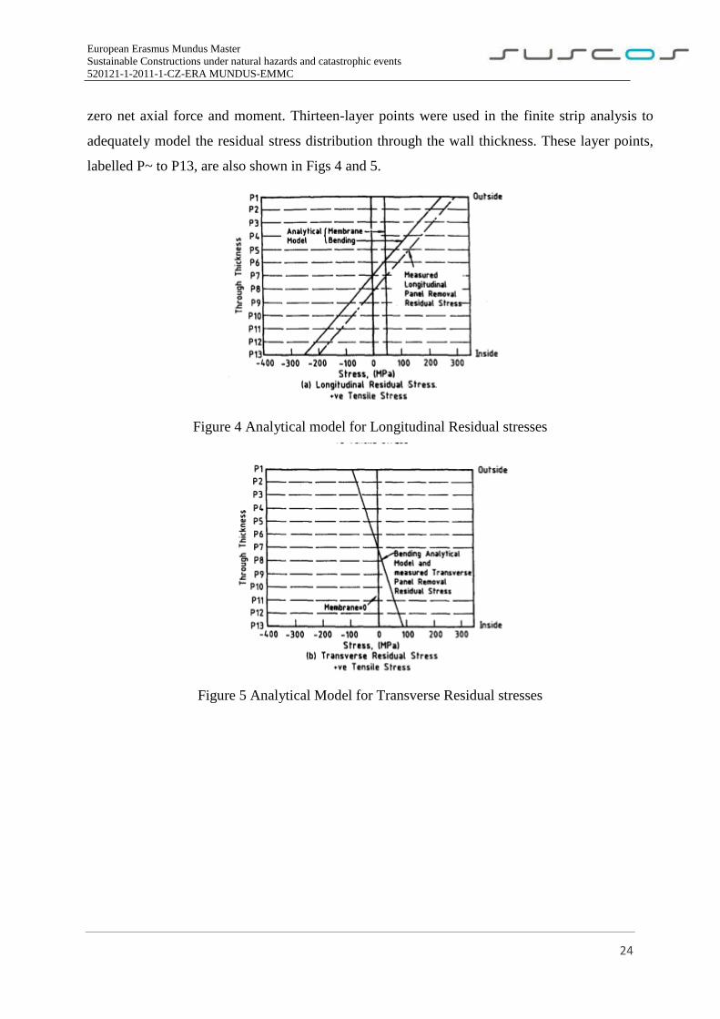
zero net axial force and moment. Thirteen-layer points were used in the finite strip analysis to
adequately model the residual stress distribution through the wall thickness. These layer points,
labelled P~ to P13, are also shown in Figs 4 and 5.
Figure 4 Analytical model for Longitudinal Residual stresses
Figure 5 Analytical Model for Transverse Residual stresses
European Erasmus Mundus Master
Sustainable Constructions under natural hazards and catastrophic events
520121-1-2011-1-CZ-ERA MUNDUS-EMMC
25
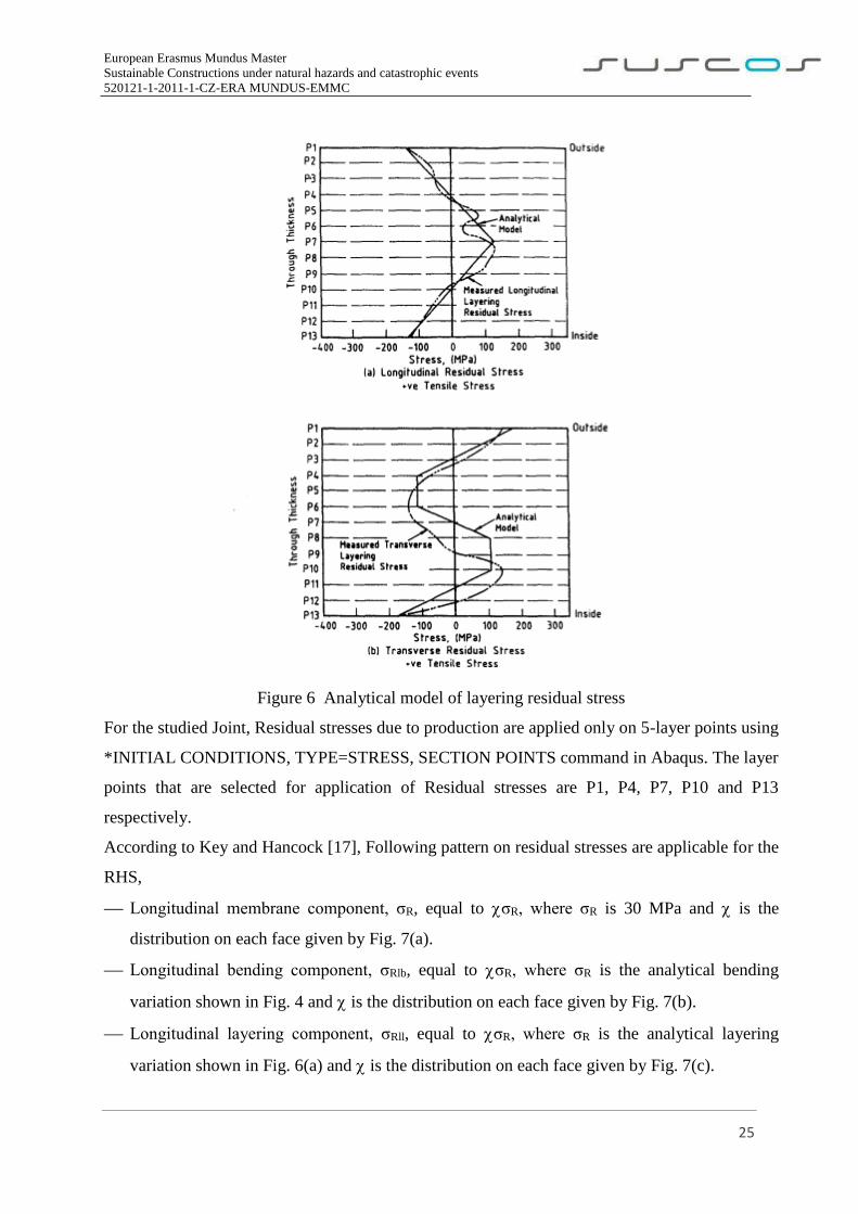
Figure 6 Analytical model of layering residual stress
For the studied Joint, Residual stresses due to production are applied only on 5-layer points using
*INITIAL CONDITIONS, TYPE=STRESS, SECTION POINTS command in Abaqus. The layer
points that are selected for application of Residual stresses are P1, P4, P7, P10 and P13
respectively.
According to Key and Hancock [17], Following pattern on residual stresses are applicable for the
RHS,
Longitudinal membrane component, σR, equal to σR, where σR is 30 MPa and is the
distribution on each face given by Fig. 7(a).
Longitudinal bending component, σRlb, equal to σR, where σR is the analytical bending
variation shown in Fig. 4 and is the distribution on each face given by Fig. 7(b).
Longitudinal layering component, σRll, equal to σR, where σR is the analytical layering
variation shown in Fig. 6(a) and is the distribution on each face given by Fig. 7(c).
European Erasmus Mundus Master
Sustainable Constructions under natural hazards and catastrophic events
520121-1-2011-1-CZ-ERA MUNDUS-EMMC
26
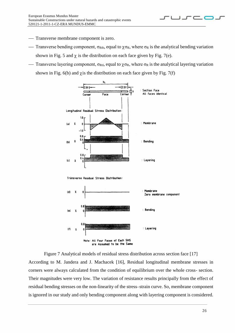
Transverse membrane component is zero.
Transverse bending component, σRtb, equal to σR, where σR is the analytical bending variation
shown in Fig. 5 and is the distribution on each face given by Fig. 7(e).
Transverse layering component, σRtl, equal to σR, where σR is the analytical layering variation
shown in Fig. 6(b) and is the distribution on each face given by Fig. 7(f)
Figure 7 Analytical models of residual stress distribution across section face [17]
According to M. Jandera and J. Machacek [16], Residual longitudinal membrane stresses in
corners were always calculated from the condition of equilibrium over the whole cross- section.
Their magnitudes were very low. The variation of resistance results principally from the effect of
residual bending stresses on the non-linearity of the stress–strain curve. So, membrane component
is ignored in our study and only bending component along with layering component is considered.
European Erasmus Mundus Master
Sustainable Constructions under natural hazards and catastrophic events
520121-1-2011-1-CZ-ERA MUNDUS-EMMC
27
2.3.2 Welding
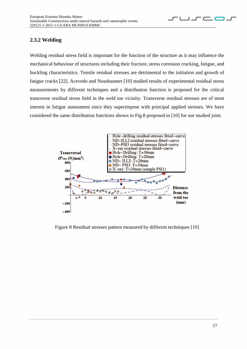
Welding residual stress field is important for the function of the structure as it may influence the
mechanical behaviour of structures including their fracture, stress corrosion cracking, fatigue, and
buckling characteristics. Tensile residual stresses are detrimental to the initiation and growth of
fatigue cracks [22]. Acevedo and Nussbaumer [10] studied results of experimental residual stress
measurements by different techniques and a distribution function is proposed for the critical
transverse residual stress field in the weld toe vicinity. Transverse residual stresses are of most
interest in fatigue assessment since they superimpose with principal applied stresses. We have
considered the same distribution functions shown in Fig.8 proposed in [10] for our studied joint.
Figure 8 Residual stresses pattern measured by different techniques [10]
European Erasmus Mundus Master
Sustainable Constructions under natural hazards and catastrophic events
520121-1-2011-1-CZ-ERA MUNDUS-EMMC
28
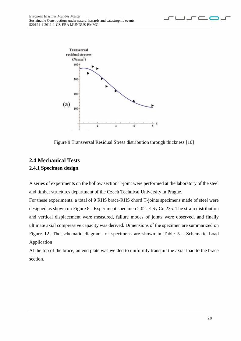
Figure 9 Transversal Residual Stress distribution through thickness [10]
2.4 Mechanical Tests
2.4.1 Specimen design
A series of experiments on the hollow section T-joint were performed at the laboratory of the steel
and timber structures department of the Czech Technical University in Prague.
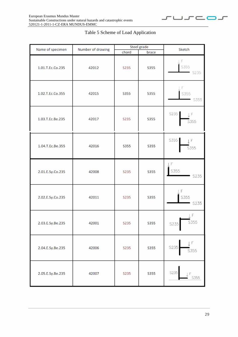
For these experiments, a total of 9 RHS brace-RHS chord T-joints specimens made of steel were
designed as shown on Figure 8 - Experiment specimen 2.02. E.Sy.Co.235. The strain distribution
and vertical displacement were measured, failure modes of joints were observed, and finally
ultimate axial compressive capacity was derived. Dimensions of the specimen are summarized on
Figure 12. The schematic diagrams of specimens are shown in Table 5 - Schematic Load
Application
At the top of the brace, an end plate was welded to uniformly transmit the axial load to the brace
section.
European Erasmus Mundus Master
Sustainable Constructions under natural hazards and catastrophic events
520121-1-2011-1-CZ-ERA MUNDUS-EMMC
29
Table 5 Scheme of Load Application
European Erasmus Mundus Master
Sustainable Constructions under natural hazards and catastrophic events
520121-1-2011-1-CZ-ERA MUNDUS-EMMC
30
2.4.2 Test procedure
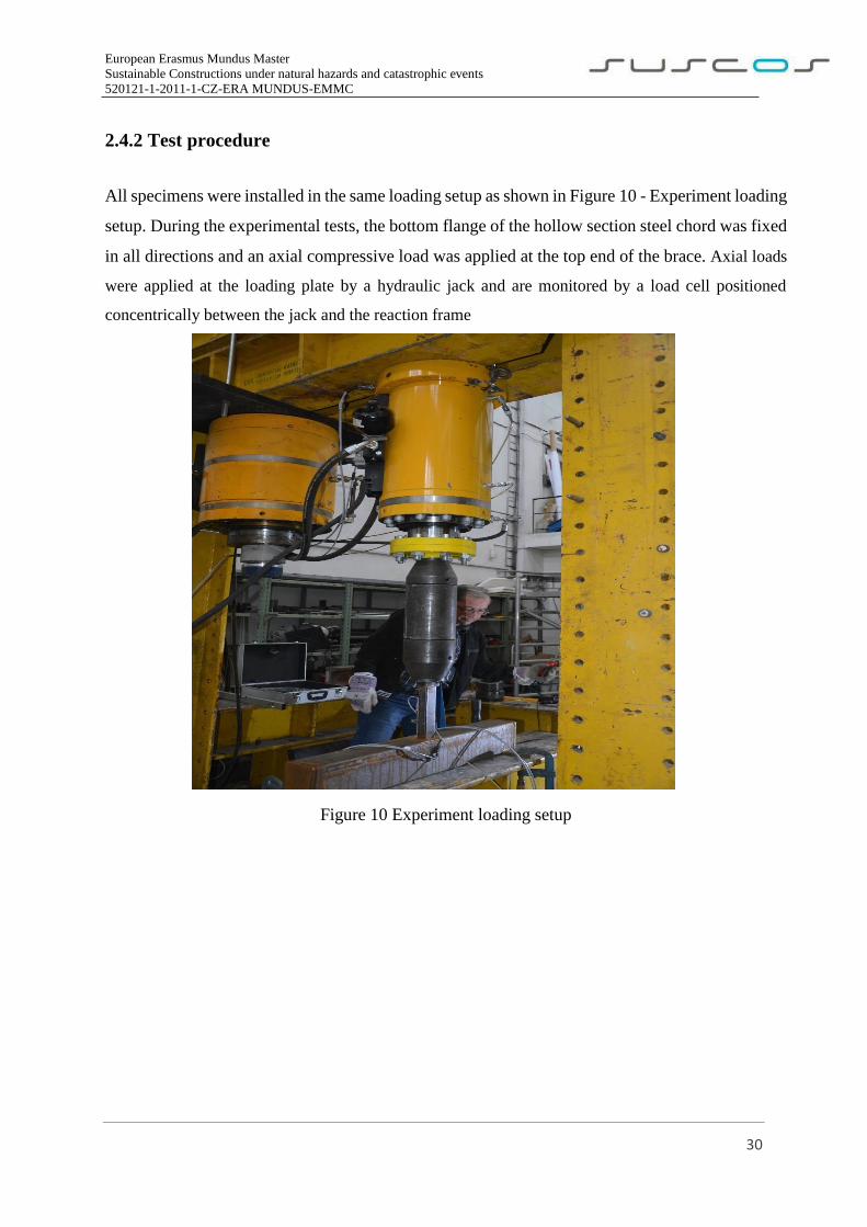
All specimens were installed in the same loading setup as shown in Figure 10 - Experiment loading
setup. During the experimental tests, the bottom flange of the hollow section steel chord was fixed
in all directions and an axial compressive load was applied at the top end of the brace. Axial loads
were applied at the loading plate by a hydraulic jack and are monitored by a load cell positioned
concentrically between the jack and the reaction frame
Figure 10 Experiment loading setup
European Erasmus Mundus Master
Sustainable Constructions under natural hazards and catastrophic events
520121-1-2011-1-CZ-ERA MUNDUS-EMMC
31
2.4.3 Measurement plan
To obtain the necessary information for the analysis, the test plan consisted of two measurement
devices:
(1) Strain gauges.
(2) Potentiometers
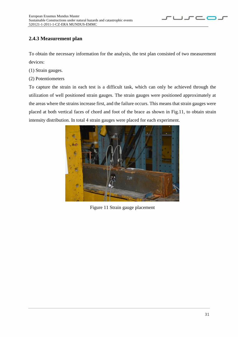
To capture the strain in each test is a difficult task, which can only be achieved through the
utilization of well positioned strain gauges. The strain gauges were positioned approximately at
the areas where the strains increase first, and the failure occurs. This means that strain gauges were
placed at both vertical faces of chord and foot of the brace as shown in Fig.11, to obtain strain
intensity distribution. In total 4 strain gauges were placed for each experiment.
Figure 11 Strain gauge placement
European Erasmus Mundus Master
Sustainable Constructions under natural hazards and catastrophic events
520121-1-2011-1-CZ-ERA MUNDUS-EMMC
32
3. Objectives
Design rules for joints between hollow sections are based on simple theoretical mechanical models
and they are fitted through comparisons with experimental tests. Nowadays, numerical models are
becoming an important tool for designing connections with accuracy and reliability, and the
present study intends to explore this field.
The primary goal for this dissertation is to study the influence of Residual stresses on the design
resistance of hollow section joints.
To achieve the primary goal, following objectives are to be achieved
Extensive study on Residual stresses and their influence in steel structural members
Study on the hollow section joints and their failure modes.
Creation of shell and solid element numerical models with the use of software ABAQUS by
using the same parameters as experimental data.
Application of different pattern and magnitude of Residual stresses on the numerical models.
Validation and verification of numerical models by comparing outputs of numerical models to
experimental and analytical results
Perform sensitivity tests on numerical models by changing geometric parameters to understand
better the strength behavior and failure modes of the T-joint.
Investigate analysis results to see the influence of Residual stresses on design resistance and
behavior of hollow section joints.
European Erasmus Mundus Master
Sustainable Constructions under natural hazards and catastrophic events
520121-1-2011-1-CZ-ERA MUNDUS-EMMC
33
4. FEA Model
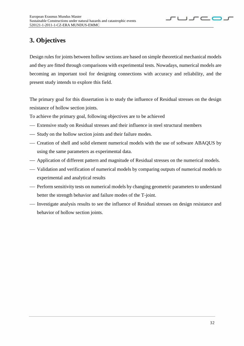
4.1 Mechanical model
We have considered Experiment specimen 2.02. E.Sy.Co.235. for this study and the validation and
verification is done to the results of this specimen in the chapter 3.
Figure 12 T-Joint model considered in this study 2.02. E.Sy.Co.235
European Erasmus Mundus Master
Sustainable Constructions under natural hazards and catastrophic events
520121-1-2011-1-CZ-ERA MUNDUS-EMMC
34
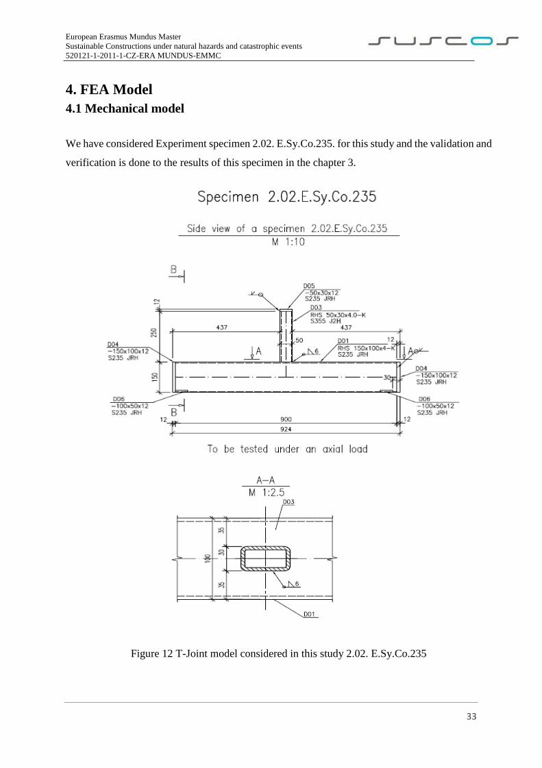
Chord Face Failure is seen as shown in Fig.13 in all the specimens tested in mechanical tests for
Compressive load from top of the brace.
Figure 13 Deformed shape of the Specimen
European Erasmus Mundus Master
Sustainable Constructions under natural hazards and catastrophic events
520121-1-2011-1-CZ-ERA MUNDUS-EMMC
35
4.2 Model Without Residual Stresses
The latest research progress and commercial finite element codes are capable to simulate almost
all complex phenomena affecting the connection response (three-dimensional behavior, combined
nonlinear phenomena like material and geometrical nonlinearities, friction, slippage, contact, Weld
interaction and fracture). However, still difficulties remain to the numerical analyst which must
choose appropriate finite element models able to provide an accurate representation of the physics
with the lowest computational cost. Choice of the mesh, node number, integration point number
through the element thickness and time-step size for constitutive law integration depend upon
resources, geometry, type of loading and required accuracy.
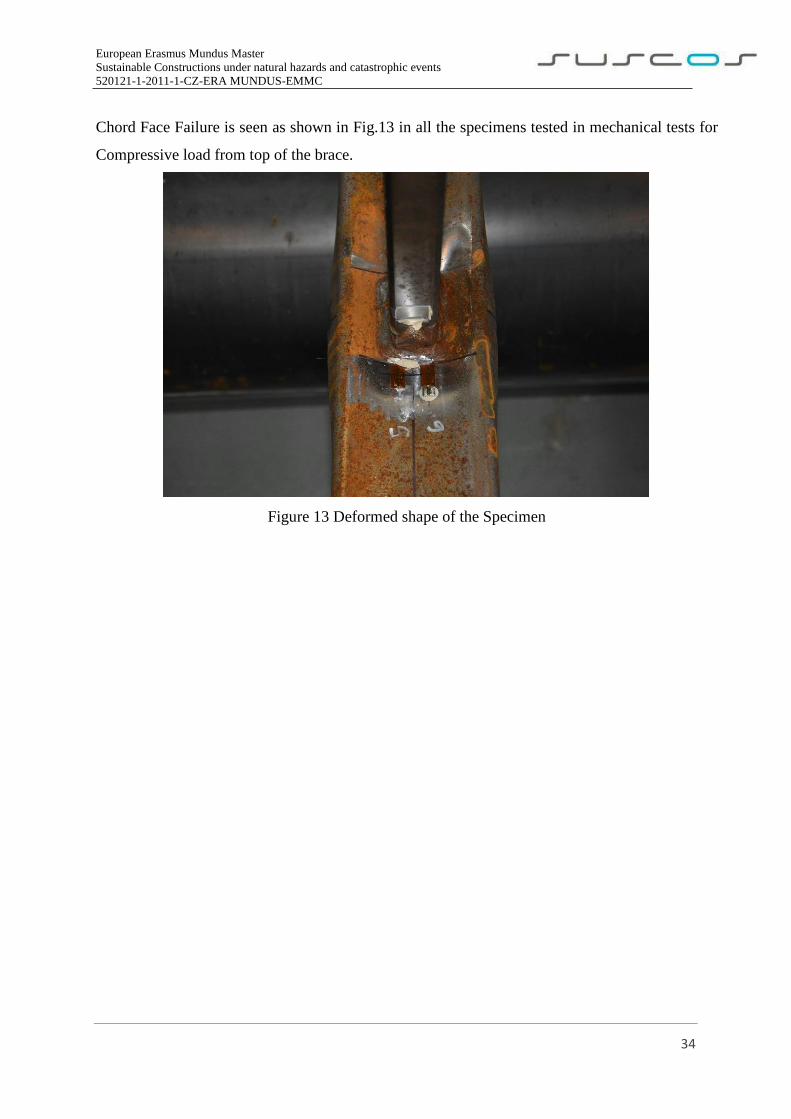
The software ABAQUS was used in the present study to model the hollow section T-joint. By
using ABAQUS 3D solid and shell elements, members of the joint could be modeled as a sharp
notch given in Fig.14. This software allowed us to apply residual stresses and it can produce
accurate and detailed stress distribution near the intersection of member and results will be later
discussed on this study.
ELEMENT TYPE AND SIZE MATERIAL
CHORD 150X100X4 S235
BRACE 50X30X4 S355
Figure 14 FE model of RHS T-Joint
European Erasmus Mundus Master
Sustainable Constructions under natural hazards and catastrophic events
520121-1-2011-1-CZ-ERA MUNDUS-EMMC
36
4.2.1 Limit Deformation
According to Wardenier [7], joint design is based on the limit state (or states), corresponding to
the “maximum load carrying capacity”. The latter is defined by criteria adopted by the IIW Sub-
commission XV-E [18], namely the lower of:
(a) The ultimate strength of the joint, and
(b) The load corresponding to an ultimate deformation limit.
An out-of-plane deformation of the corresponding RHS face, equal to 3% of the RHS connecting
face width (0,03b0), is generally used as the ultimate deformation limit [19] in (b) above. This
serves to control joint deformations at both the factored and service load levels, which is often
necessary because of the high flexibility of some RHS joints. In general, this ultimate deformation
limit also restricts joint service load deformations to ≤ 0,01b0. Wardenier et al. wrote [7] that,
some design provisions for RHS joints are based on experiments undertaken in the 70’s, prior to
the introduction of this deformation limit and where ultimate deformations may have exceeded
0,03b0. However, such design formulae have proved to be satisfactory in practice.
Also, according to Chen & Wu, for the deformation curves of SHS brace-H-shaped steel chord T-
joints with no distinct peaks and a drop load, the joint strength F 3% of b0 at the deformation of
3% of the chord width (b0), was a failure load. But, for Chen & Wu experiments, the deformation
of all axially loaded T-joints was less than 3% of b0. For this, the ultimate limit state was the last
criterion used to define failure in the joints. So, the useful experimental data was obtained before
specimens suddenly buckling failure, and the top point of curve was defined as ultimate capacity.
4.2.2. Maximum strain
For the failure modes of the FE models, it was taken into consideration the limit state criteria
according to EN 1993 1-5 cl. C.8 (1) [3], “the national annex may specify the limiting of principal
strain. A value of 5% is recommended.” This means that a failure mode is reached once any part
of the specimen reaches the strain of 5%.
European Erasmus Mundus Master
Sustainable Constructions under natural hazards and catastrophic events
520121-1-2011-1-CZ-ERA MUNDUS-EMMC
37
4.2.3. Type of structural analysis
The type of analysis chosen in ABAQUS to assess the hollow section T-Joint was the static, Riks
method. This method is generally used to predict unstable, geometrically nonlinear collapse of a
structure.
The constitutive model is integrated by means of the explicit forward Euler algorithm. To
determine the structural response of the nonlinear problem, an implicit solution strategy is used.
Hence, a load stepping is used. The increment size follows from accuracy and convergence criteria.
Within each increment, the equilibrium equations are solved by means of the Newton-Raphson
iteration [20].
In the end of each load increment, or group of increments, the coordinates of the structure are
updated to the deformed configuration. In the next increment, these coordinates start to belong to
an “undisturbed” configuration and the stresses already installed due to the previous increments
are treated as initial stresses referent to a deformation equal to zero. This process goes on,
increment by increment, until the end of the analysis. In finite elements, the mesh keeps connected
to the integration points during all the process if the correct features are applied. The load
increments are intervals of loads, useful in a way that it allows to analyze the joint behavior in a
restrict number of intervals demanded by the user, according to the joint to be analyzed and
regarding the deformation capacity of the material. Thus, as the applied loads on the joint are
slowly enough, it is acceptable to consider the inertia forces negligible and a static analysis on the
joint can be used [21].
Considering all these above referred aspects, the type of analysis considered in the numerical
modelling is a static analysis with an elastic-plastic steel behaviour.
European Erasmus Mundus Master
Sustainable Constructions under natural hazards and catastrophic events
520121-1-2011-1-CZ-ERA MUNDUS-EMMC
38
4.2.4. Material properties
According to [21], steel is the material of the specimens. As an isotropic material, the steel used
has the same characteristics in all directions, which means that has symmetrical characteristics in
relation to one arbitrary orientation plane.
The bilinear material model in ABAQUS library was used in the finite element analysis. The initial
part of the bilinear curve represents the elastic property up to tensile yield stress (fy), with measured
elastic modulus (E) and Poisson’s ratio (ν). The post-yield response of the bilinear material model
was developed based on the measured ultimate tensile stress (fu) and elongation [38].
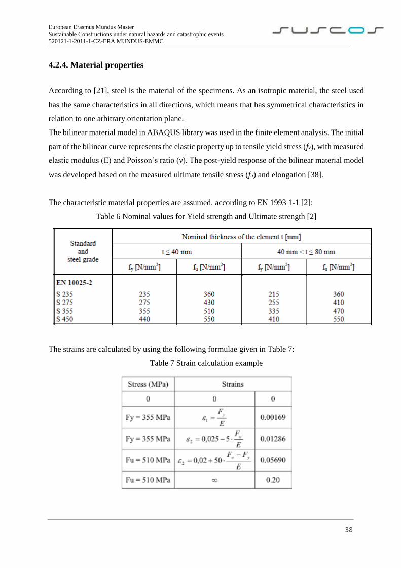
The characteristic material properties are assumed, according to EN 1993 1-1 [2]:
Table 6 Nominal values for Yield strength and Ultimate strength [2]
The strains are calculated by using the following formulae given in Table 7:
Table 7 Strain calculation example
European Erasmus Mundus Master
Sustainable Constructions under natural hazards and catastrophic events
520121-1-2011-1-CZ-ERA MUNDUS-EMMC
39
4.2.5. Mesh
The finite element mesh stands for one of the most important aspects for an accurate result in a
numerical simulation. A finer finite element mesh usually gives better calculation results.
However, as a mesh is made finer, the computation time and cost increases. A finer mesh depends
on many factors. Among them is the cost versus the accuracy to receive. The cost increases with
the number of DOF’s.
The mesh density required can be a function of many factors. Among them are the stress gradients,
the type of loadings, the boundary conditions, the element types used, the element shapes, and the
degree of accuracy desired.
The type of the mesh elements (quadratic or triangular) also play an important role to consider for
the refinement process, being necessary for such process, to have in consideration the shape of the
mesh for the structural elements (undistorted or distorted).
It is important to keep the elements with an appropriate aspect ratio. Also, elements must not cross
interference to be able to capture the higher stress concentration which occurs on those areas. The
good practice also tells that is preferable to use quadrilateral over triangles for 2D models, and
bricks over wedges and tetrahedral for 3D models.
Distortion of the element should be taken into consideration when meshing a model. For this study,
it was chosen quadratic elements with four nodes for shell elements and 3D elements containing 8
nodes for solid elements. Ideal size of the mesh should be a result of a convergence study to
combine higher accuracy of the results and lower time/cost of the computational processing.
The stiffness, mass and volume of an element are calculating numerically through the called
“integration points”. These points influence the element’s behavior, which can be analyzed by a
full or reduced integration. The difference between these types of integration is on the number of
points needed to integrate the polynomials of the matrices required to develop the finite element
method.
European Erasmus Mundus Master
Sustainable Constructions under natural hazards and catastrophic events
520121-1-2011-1-CZ-ERA MUNDUS-EMMC
40
4.2.6. Support and load conditions
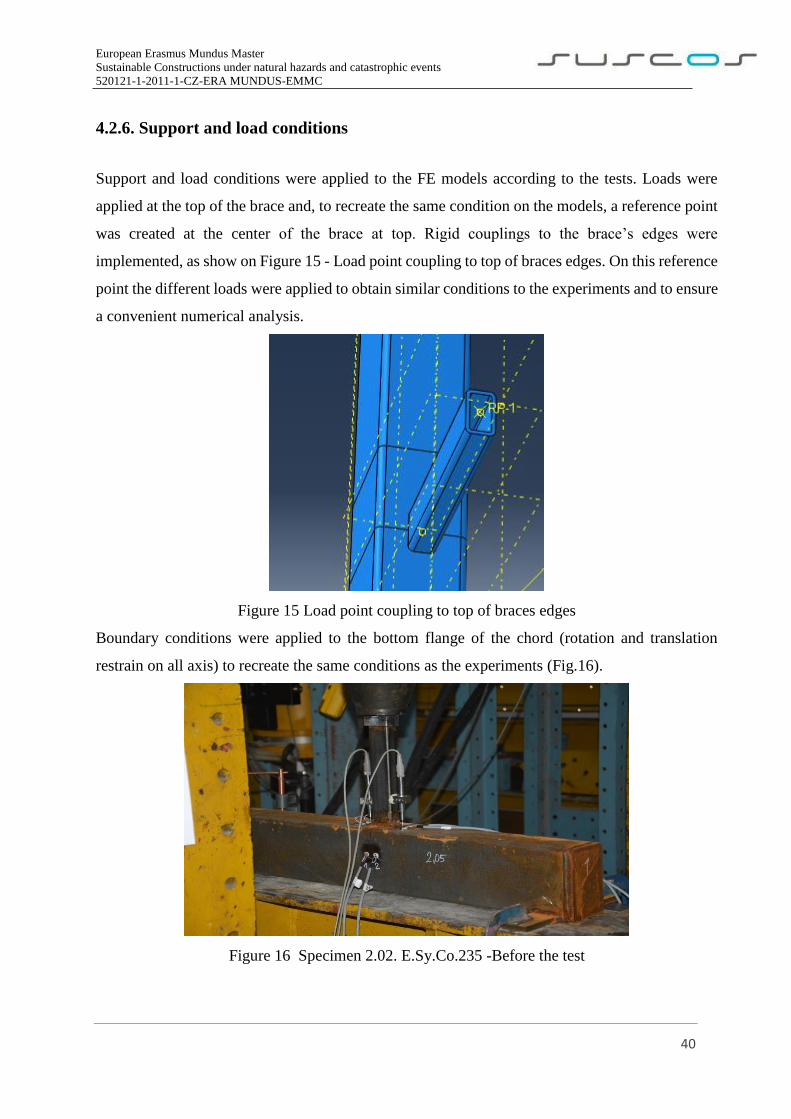
Support and load conditions were applied to the FE models according to the tests. Loads were
applied at the top of the brace and, to recreate the same condition on the models, a reference point
was created at the center of the brace at top. Rigid couplings to the brace’s edges were
implemented, as show on Figure 15 - Load point coupling to top of braces edges. On this reference
point the different loads were applied to obtain similar conditions to the experiments and to ensure
a convenient numerical analysis.
Figure 15 Load point coupling to top of braces edges
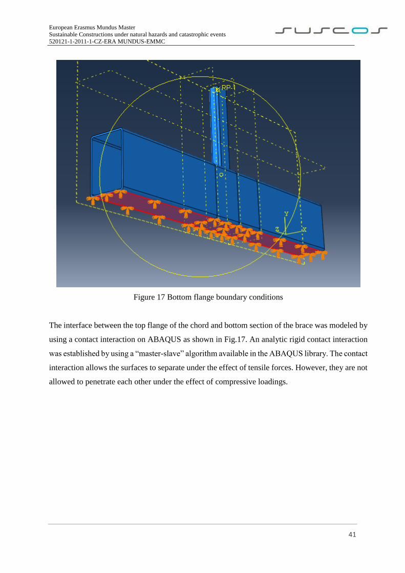
Boundary conditions were applied to the bottom flange of the chord (rotation and translation
restrain on all axis) to recreate the same conditions as the experiments (Fig.16).
Figure 16 Specimen 2.02. E.Sy.Co.235 -Before the test
European Erasmus Mundus Master
Sustainable Constructions under natural hazards and catastrophic events
520121-1-2011-1-CZ-ERA MUNDUS-EMMC
41
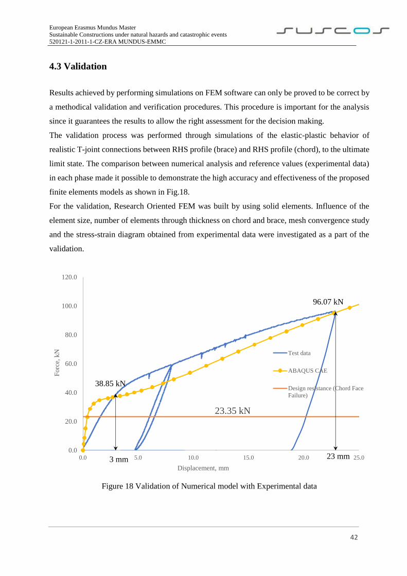
Figure 17 Bottom flange boundary conditions
The interface between the top flange of the chord and bottom section of the brace was modeled by
using a contact interaction on ABAQUS as shown in Fig.17. An analytic rigid contact interaction
was established by using a “master-slave” algorithm available in the ABAQUS library. The contact
interaction allows the surfaces to separate under the effect of tensile forces. However, they are not
allowed to penetrate each other under the effect of compressive loadings.
European Erasmus Mundus Master
Sustainable Constructions under natural hazards and catastrophic events
520121-1-2011-1-CZ-ERA MUNDUS-EMMC
42
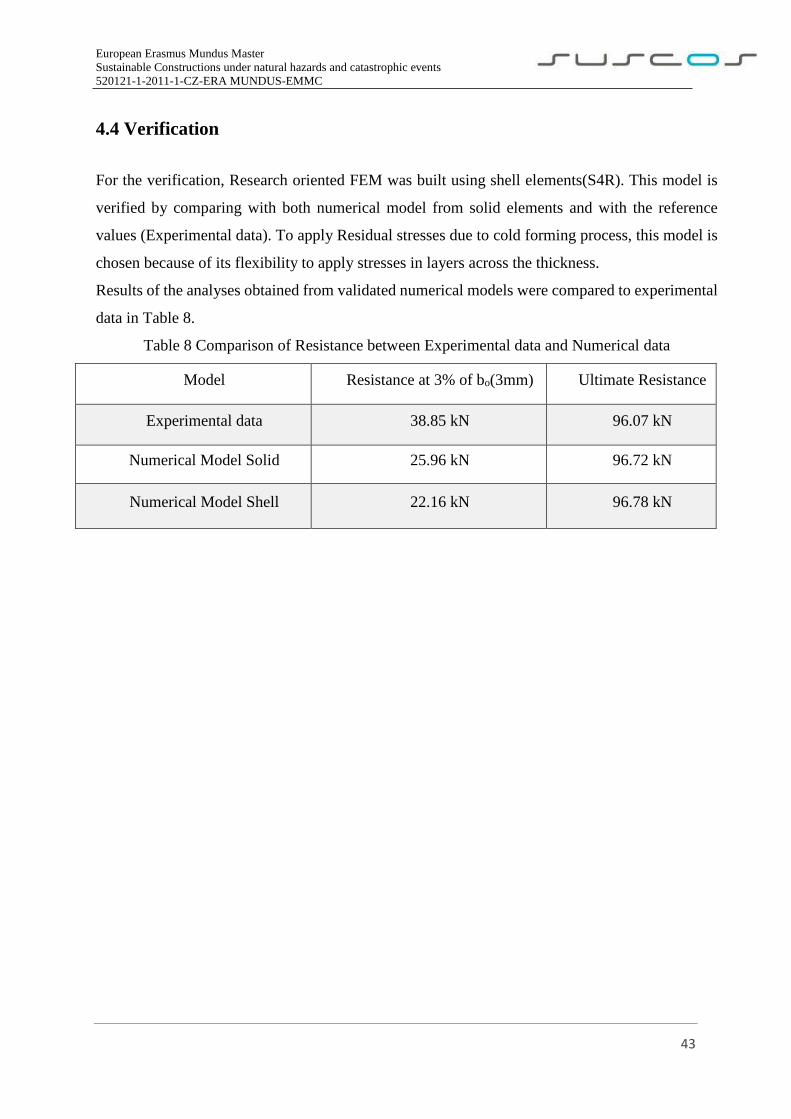
4.3 Validation
Results achieved by performing simulations on FEM software can only be proved to be correct by
a methodical validation and verification procedures. This procedure is important for the analysis
since it guarantees the results to allow the right assessment for the decision making.
The validation process was performed through simulations of the elastic-plastic behavior of
realistic T-joint connections between RHS profile (brace) and RHS profile (chord), to the ultimate
limit state. The comparison between numerical analysis and reference values (experimental data)
in each phase made it possible to demonstrate the high accuracy and effectiveness of the proposed
finite elements models as shown in Fig.18.
For the validation, Research Oriented FEM was built by using solid elements. Influence of the
element size, number of elements through thickness on chord and brace, mesh convergence study
and the stress-strain diagram obtained from experimental data were investigated as a part of the
validation.
Figure 18 Validation of Numerical model with Experimental data
23.35 kN
0.0
20.0
40.0
60.0
80.0
100.0
120.0
0.0 5.0 10.0 15.0 20.0 25.0
Fo
rce,
kN
Displacement, mm
Test data
ABAQUS CAE
Design resistance (Chord Face
Failure)
38.85 kN
3 mm
96.07 kN
23 mm
European Erasmus Mundus Master
Sustainable Constructions under natural hazards and catastrophic events
520121-1-2011-1-CZ-ERA MUNDUS-EMMC
43
4.4 Verification
For the verification, Research oriented FEM was built using shell elements(S4R). This model is
verified by comparing with both numerical model from solid elements and with the reference
values (Experimental data). To apply Residual stresses due to cold forming process, this model is
chosen because of its flexibility to apply stresses in layers across the thickness.
Results of the analyses obtained from validated numerical models were compared to experimental
data in Table 8.
Table 8 Comparison of Resistance between Experimental data and Numerical data
Model Resistance at 3% of bo(3mm) Ultimate Resistance
Experimental data 38.85 kN 96.07 kN
Numerical Model Solid 25.96 kN 96.72 kN
Numerical Model Shell 22.16 kN 96.78 kN
European Erasmus Mundus Master
Sustainable Constructions under natural hazards and catastrophic events
520121-1-2011-1-CZ-ERA MUNDUS-EMMC
44
5. Sensitivity Study
5.1 Application of Residual Stresses on the model
In this study, Exclusive study was performed on the rectangular hollow section T-Joint. RHS
150x100x4 as a chord and 50x30x4 as brace were used for modelling. The bilinear material model
of steel including the elastic modulus (E) OF 205 GPa, tensile yield stress of 355 MPa for brace and
235 MPa for chord and Poisson’s ratio (ν) of 0,3 were used in the study. For the deformation curves of
the joints with clear peak load, the peak load was used as the failure load, which occurs in all cases
(Chord Face Failure).
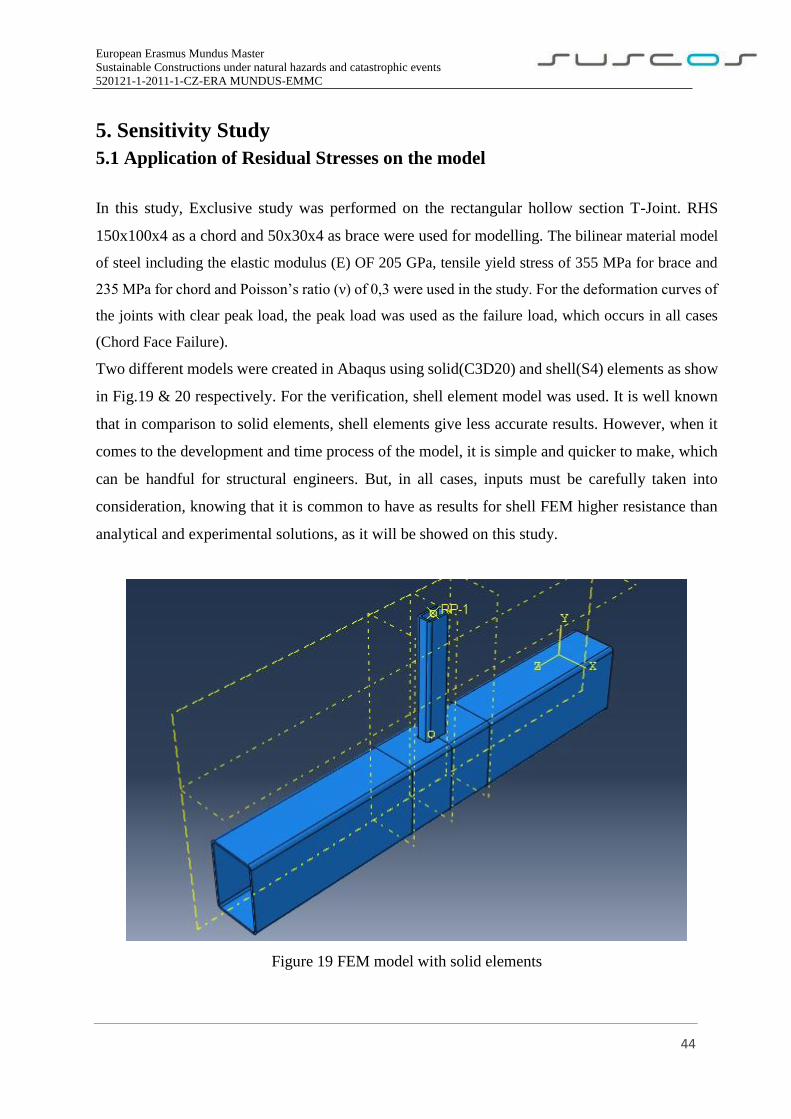
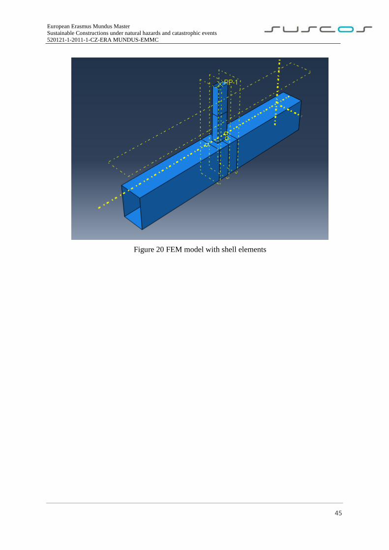
Two different models were created in Abaqus using solid(C3D20) and shell(S4) elements as show
in Fig.19 & 20 respectively. For the verification, shell element model was used. It is well known
that in comparison to solid elements, shell elements give less accurate results. However, when it
comes to the development and time process of the model, it is simple and quicker to make, which
can be handful for structural engineers. But, in all cases, inputs must be carefully taken into
consideration, knowing that it is common to have as results for shell FEM higher resistance than
analytical and experimental solutions, as it will be showed on this study.
Figure 19 FEM model with solid elements
European Erasmus Mundus Master
Sustainable Constructions under natural hazards and catastrophic events
520121-1-2011-1-CZ-ERA MUNDUS-EMMC
45
Figure 20 FEM model with shell elements
European Erasmus Mundus Master
Sustainable Constructions under natural hazards and catastrophic events
520121-1-2011-1-CZ-ERA MUNDUS-EMMC
46
5.2 Results and Discussions
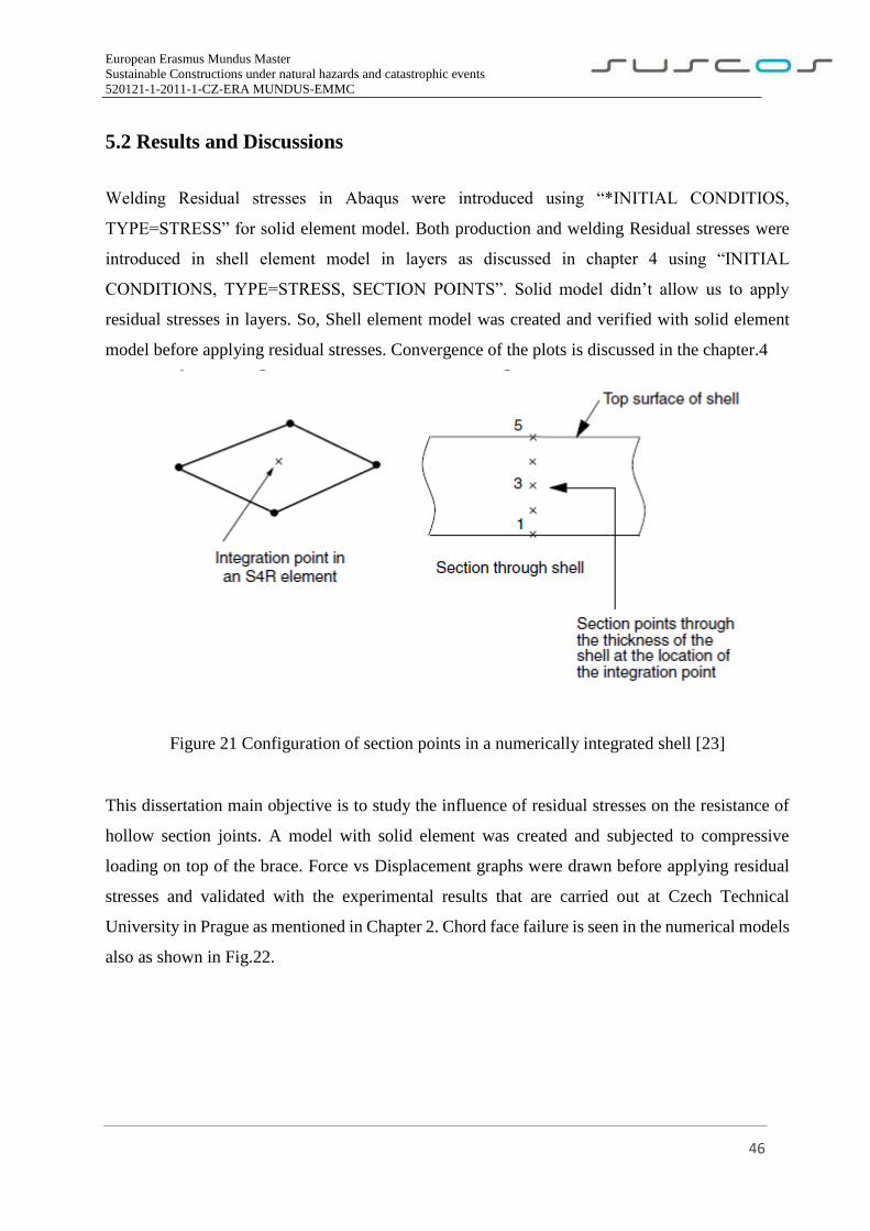
Welding Residual stresses in Abaqus were introduced using “*INITIAL CONDITIOS,
TYPE=STRESS” for solid element model. Both production and welding Residual stresses were
introduced in shell element model in layers as discussed in chapter 4 using “INITIAL
CONDITIONS, TYPE=STRESS, SECTION POINTS”. Solid model didn’t allow us to apply
residual stresses in layers. So, Shell element model was created and verified with solid element
model before applying residual stresses. Convergence of the plots is discussed in the chapter.4
Figure 21 Configuration of section points in a numerically integrated shell [23]
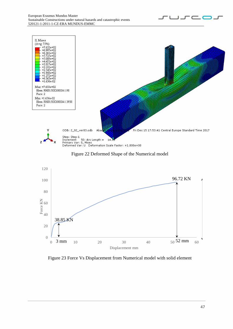
This dissertation main objective is to study the influence of residual stresses on the resistance of
hollow section joints. A model with solid element was created and subjected to compressive
loading on top of the brace. Force vs Displacement graphs were drawn before applying residual
stresses and validated with the experimental results that are carried out at Czech Technical
University in Prague as mentioned in Chapter 2. Chord face failure is seen in the numerical models
also as shown in Fig.22.
European Erasmus Mundus Master
Sustainable Constructions under natural hazards and catastrophic events
520121-1-2011-1-CZ-ERA MUNDUS-EMMC
47
Figure 22 Deformed Shape of the Numerical model
Figure 23 Force Vs Displacement from Numerical model with solid element
0
20
40
60
80
100
120
0 10 20 30 40 50 60
Fo
rce
KN
Displacement mm
38.85 KN
3 mm
96.72 KN
52 mm
European Erasmus Mundus Master
Sustainable Constructions under natural hazards and catastrophic events
520121-1-2011-1-CZ-ERA MUNDUS-EMMC
48
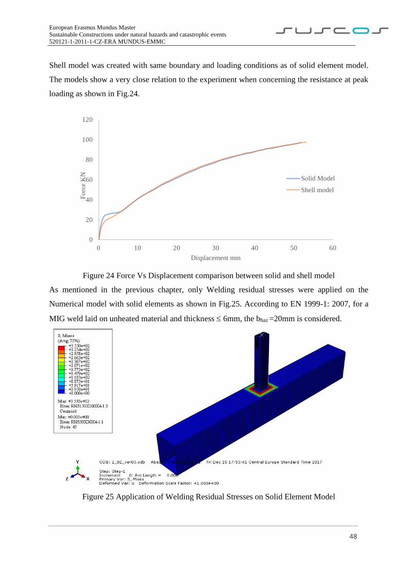
Shell model was created with same boundary and loading conditions as of solid element model.
The models show a very close relation to the experiment when concerning the resistance at peak
loading as shown in Fig.24.
Figure 24 Force Vs Displacement comparison between solid and shell model
As mentioned in the previous chapter, only Welding residual stresses were applied on the
Numerical model with solid elements as shown in Fig.25. According to EN 1999-1: 2007, for a
MIG weld laid on unheated material and thickness 6mm, the bhaz =20mm is considered.
Figure 25 Application of Welding Residual Stresses on Solid Element Model
0
20
40
60
80
100
120
0 10 20 30 40 50 60
Fo
rce
KN
Displacement mm
Solid Model
Shell model
European Erasmus Mundus Master
Sustainable Constructions under natural hazards and catastrophic events
520121-1-2011-1-CZ-ERA MUNDUS-EMMC
49
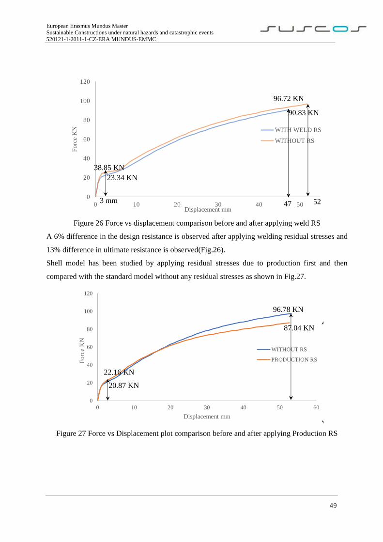
Figure 26 Force vs displacement comparison before and after applying weld RS
A 6% difference in the design resistance is observed after applying welding residual stresses and
13% difference in ultimate resistance is observed(Fig.26).
Shell model has been studied by applying residual stresses due to production first and then
compared with the standard model without any residual stresses as shown in Fig.27.
Figure 27 Force vs Displacement plot comparison before and after applying Production RS
0
20
40
60
80
100
120
0 10 20 30 40 50
Fo
rce
KN
Displacement mm
WITH WELD RS
WITHOUT RS
38.85 KN
3 mm
96.72 KN
52
23.34 KN
47
90.83 KN
0
20
40
60
80
100
120
0 10 20 30 40 50 60
Fo
rce
KN
Displacement mm
WITHOUT RS
PRODUCTION RS
96.78 KN
87.04 KN
22.16 KN
20.87 KN
European Erasmus Mundus Master
Sustainable Constructions under natural hazards and catastrophic events
520121-1-2011-1-CZ-ERA MUNDUS-EMMC
50
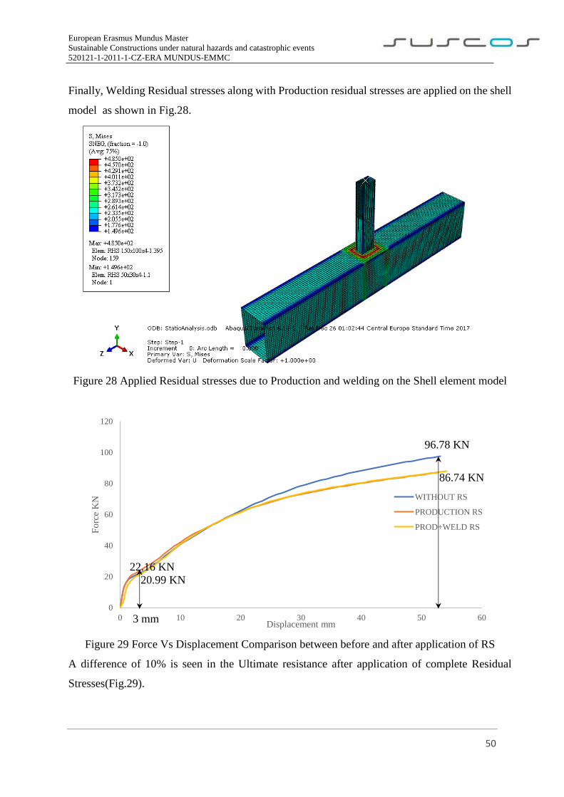
Finally, Welding Residual stresses along with Production residual stresses are applied on the shell
model as shown in Fig.28.
Figure 28 Applied Residual stresses due to Production and welding on the Shell element model
Figure 29 Force Vs Displacement Comparison between before and after application of RS
A difference of 10% is seen in the Ultimate resistance after application of complete Residual
Stresses(Fig.29).
0
20
40
60
80
100
120
0 10 20 30 40 50 60
Fo
rce
KN
Displacement mm
WITHOUT RS
PRODUCTION RS
PROD+WELD RS
96.78 KN
86.74 KN
22.16 KN
3 mm
20.99 KN
European Erasmus Mundus Master
Sustainable Constructions under natural hazards and catastrophic events
520121-1-2011-1-CZ-ERA MUNDUS-EMMC
51
6. Summary
6.1 Conclusions
Considering the obtained results on this dissertation, it can also be concluded that:
Shell element FE model is not the most adequate numerical solution to verify the studied joint
resistance but was studied to see the Production Residual stresses behavior when applied in
layers.
Shell element models provide us with the flexibility to apply residual stresses on each layer
(Section points) where as Solid element model doesn’t allow us to apply Residual stresses in
layers (Can be applied in layers using SIGINI user routine but this method is quite complex
and not easy for beginner level users).
Resistance at 3% bo in case of solid element model after applying welding residual stresses
was reduced by 40% which clearly implicates the effect of residual stresses in this zone.
Influence of Residual stresses generated due to welding process at the joint reduces the
Ultimate Resistance by 13% Approximately in the case of solid element numerical model.
Production residual stresses were applied on the shell element model and only 6% reduction
of resistance was seen at 3%bo whereas Ultimate resistance was decreased by 11%.
Welding Residual stresses when applied along with the Production Residual stresses decrease
resistance to 10% approximately at failure and 5% approximately at 3%bo. There is a very
slight increase in resistance when applied together due to compressive Residual stress
component which acts against the loading.
Finally, it can be concluded that influence of Residual Stresses on the resistance of hollow section
joint is negligible at Ultimate resistance. So, it is not necessary to consider separately during the
design of joint but where as in the range of elasticity they play some role depending on the
component direction which needs to be considered.
European Erasmus Mundus Master
Sustainable Constructions under natural hazards and catastrophic events
520121-1-2011-1-CZ-ERA MUNDUS-EMMC
52
6.2 Future Developments Along the development of this dissertation, it was noted a necessity for more information in some
fields of application where some further investigations could be taken, such as:
Experiments should be done by also implementing measured values of imperfections on
experiments, so that, in accordance to EN1993 1-6, these imperfections could be reflected
on the FE models with accuracy.
To perform convergence studies of shell element FE models by using different types of
mesh elements and size to obtain accurate results
To further analyse and improve the action of welded joint on FE models. It is necessary to
refine the results by representing the true weld properties on the models.
Although the model didn’t show any major difference in Ultimate resistance, it is necessary
to cross check the influence of these residual stresses by studying different types of model
and Cross sections.
To study further on the influence of residual stresses in the range of elasticity as the design
standards allow the maximum deformation that can be considered only in this zone (3% of
bo)
European Erasmus Mundus Master
Sustainable Constructions under natural hazards and catastrophic events
520121-1-2011-1-CZ-ERA MUNDUS-EMMC
53
References
[1]. Jeffrey A. Packer, Jaap Wardenier, Xiao-Ling Zhao, Addie van der Vegte and Yoshiaki
Kurobane, “Design guide for rectangular hollow section (RHS) joints under predominantly static
loading”, Comité International pour le Développement et l'Etude de la Construction Tubulaire,
2009.
[2]. CEN, European Committee for Standardization “EN 1993-1-1, Eurocode 3 – Design of steel
structures – Part 1 -1: General rules and rules for buildings”, Brussels, 2005.
[3]. CEN, European Committee for Standardization “EN 1993-1-8, Eurocode 3 – Design of steel
structures – Part 1 -8: Design of joints”, Brussels, 2005.
[4]. Hollow Section Joints by J.Wardenier, Delft University Press.
[5]. Gurney T.R., Fatigue of Welded Structures, Cambridge Univ. Press, 1979.
[6]. Krebs.J, Kassner.M, Alstom-LHB, “Influence of welding residual stresses on fatigue design
of welded joints and components”, Welding in the World, 2007.
[7]. Wardenier.J, “Hollow sections in structural applications”, Comité International pour le
Développement et l'Etude de la Construction Tubulaire.
[8]. Gardner.L, Bu.Y. and Theofanous.M, “Laser‐welded stainless steel I‐sections: Residual stress
measurements and column buckling tests”, Engineering Structures, 2016.
[9]. Paradowska.A, Price.J.W.H, Dayawansa.P, Kerezsi.B, Zhao.X-Land Ibrahim.R,
“Measurement of residual stress Distribution in tubular joints considering post weld heat
treatment”, Materials forum, 2006.
[10]. Acevedo.C, Nussbaumer.A, “Residual Stress Estimation of Welded Tubular K-joints under
Fatigue Loads”, Swiss Federal Institute of Technology, Lausanne, Switzerland.
[11]. Handbook of Residual Stress and Deformation of Steel, ASM International society, 2002.
[12]. De Matos R.M.M.P, Costa-Neves L.F, L.R.O. de Lima, Vellasco P.C.G.S, J.G.S. da Silva,”
Resistance and elastic stiffness of RHS “T” joints: part I - axial brace loading”, Latin American
Journal of Solids and Structures, 2015.
[13]. X.-L. Zhao, “Deformation limit and ultimate strength of welded T-joints in cold-formed RHS
sections”, Journal of Constructional Steel Research, 2000.
[14]. Withers P. J. and Bhadeshia H. K. D. H, “Residual stress Part 1 – Measurement techniques”,
Materials Science and Technology, 2001.
European Erasmus Mundus Master
Sustainable Constructions under natural hazards and catastrophic events
520121-1-2011-1-CZ-ERA MUNDUS-EMMC
54
[15]. Tso-Liang Teng, Ching Ping Fung, Peng Hsiang Chang, Wei Chun Yang, “Analysis of
Residual stresses and distortions in T Joint Fillet Welds”, International Journal of Pressure Vessels
and Pipings, 2001.
[16]. Jandera.M and Machacek.J, “Residual stress influence on material properties and column
behaviour of stainless steel SHS”, Thin-Walled Structures, Elsevier Journal, 2014.
[17]. Peter W. Key and Gregory J. Hancock, “A theoretical investigation of the column behavior
of cold formed Square Hollow Sections”, Thin-Walled Structures, Elsevier Journal, 1993.
[18]IIW@(http://www.iiwelding.org/TheIIW/Organization/Pages/WGStand.aspx).(http://www.ii
welding.org). Visited on 26th November, 2017.
[19]. Lu L, Winkel.H, Wardenier J, “Deformation limit for the ultimate strength of hollow sections
joints”. Proceedings 6th International Symposium on Tubular Structures, Melbourne, Rotterdam,
1994.
[20]. Simões da Silva.L, Santiago.A, “Manual de ligações metálicas”. Research project:
Continuing Education in Structural Connections. CMM, Associação Portuguesa de Construção
Metálica e Mista, Coimbra, Portugal, 2003.
[21]. Dias da Silva.V, “Introdução á Análise Não Linear de Estruturas”. Faculdade de Ciências e
Tecnologia da Universidade de Coimbra, Departamento de Engenharia Civil, Coimbra, Portugal,
2002.
[22]. Xiangyang lu, “Influence of residual stress on fatigue failure of welded joints”, Doctoral
Thesis, North Carolina State University.
[23]. ABAQUS 6.13. Abaqus/CAE User’s Manual version 6.13, Dassault Systems Simulia Corp.,
Providence, RI, US, 2013.


![Prediction of welding residual stresses using machine ... · characterise the distribution of residual stresses in structural welds [6, 7]. With the development of residual stress](https://img.pdfslide.us/doc/110x75/5fa3f63f3be93a3412525cc3/prediction-of-welding-residual-stresses-using-machine-characterise-the-distribution.jpg)