Embed Size (px)
Citation preview
Investigation of IEEE standard 802.11 Medium AccessControl (MAC) layer in ad-hoc networks and comparisonwith IEEE 802.16 distributed mesh networks
Master thesis performed in Electronics Systemsby
Fernando Garcia Torre
LiTH-ISY-EX--06/3890--SE
Linköping May 2006
Investigation of IEEE standard 802.11 Medium Access Control (MAC) layer inad-hoc networks and comparison with IEEE 802.16 distributed mesh networks
Master thesis in Electronics System at Linköping Institute of Technology
by
Fernando Garcia Torre
LiTH-ISY-EX--06/3890--SE
Supervisor: Kent Palmkvist
Examiner: Kent PalmkvistLinköping May 2006
Presentation Date 2006-05-19 Publishing Date (Electronic version) 2006-06-
Department and Division Electrical Engineering (ISY) Electronics Systems
Language X English Other (specify below) Number of Pages 65
Type of Publication Licentiate thesis X Degree thesis Thesis C-level Thesis D-level Report Other (specify below)
ISBN (Licentiate thesis) ISRN: LiTH-ISY-EX--06/3890--SE
Title of series (Licentiate thesis) Series number/ISSN (Licentiate thesis)
URL, Electronic Version http://urn.kb.se/resolve?urn=urn:nbn:se:liu:diva-3890
Publication Title Investigation of IEEE standard 802.11 Medium Access Control (MAC) layer in ad-hoc networks and comparison with IEEE 802.16 distributed mesh networks Author(s) Fernando García Torre
Abstract This thesis involved a research of mechanisms of MAC layer in the ad-hoc networks environment, the ad-hoc networks in the terminology of the standard are called IBSS Independent Basic Service, these type of networks are very useful in real situation where there are not the possibility of display a infrastructure, when there isn’t a network previous planning. The connection to a new network is one of the different with the most common type of Wireless Local Area Networks (WLAN) that are the ones with infrastructure. The connection is established without the presence of a central station, instead the stations discover the others with broadcast messages in the coverage area of each station. In the context of standard 802.11 networks the communication between the stations is peer to peer, only with one hop. To continue with initiation process is necessary the synchronization between the different stations of his timers. The other capital mechanism that is treated is the medium access mechanism, to hold a shared and unreliable medium, all the heavy of this issue goes to the distributed coordination function DCF. In this moment there is an emergent technology, WIMAX or standard IEEE 802.16, like the standard 802.11 is a wireless communication protocol. Some comparison between the MAC layer mechanisms would be realized between these two standards
Keywords
MAC, 802.11, Ad-hoc networks, Access control, Coordination functions, Initiation, Scanning, Synchronization
Abstract
This thesis involved a research of mechanisms of MAC layer in the ad-hoc networksenvironment, the ad-hoc networks in the terminology of the standard are called IBSSIndependent Basic Service, these type of networks are very useful in real situationwhere there are not the possibility of display a infrastructure, when there isn’t a networkprevious planning.
The connection to a new network is one of the different with the most common type ofWireless Local Area Networks (WLAN) that are the ones with infrastructure. Theconnection is established without the presence of a central station, instead the stationsdiscover the others with broadcast messages in the coverage area of each station. In thecontext of standard 802.11 networks the communication between the stations is peer topeer, only with one hop. To continue with initiation process is necessary thesynchronization between the different stations of his timers.
The other capital mechanism that is treated is the medium access mechanism, to hold ashared and unreliable medium, all the heavy of this issue goes to the distributedcoordination function DCF.
In this moment there is an emergent technology, WIMAX or standard IEEE 802.16, likethe standard 802.11 is a wireless communication protocol. Some comparison betweenthe MAC layer mechanisms would be realized between these two standards.
IEEE 802.11 MAC layer
1 Introduction ..................................................................................................................11.1 Types topologies......................................................................................................2
1.1.1 Infrastructure networks.....................................................................................21.1.2 IBSS or Ad hoc networks.................................................................................3
1.2 Logical Link Control LCC......................................................................................41.2.1 IEEE 802.2 LLC services.................................................................................5
1.2.1.1 Unacknowledge connectionless service....................................................51.2.1.2 Connection-oriented service......................................................................51.2.1.3 Acknowledged connectionless service......................................................6
1.3 IEEE 802.11 reference model..................................................................................71.4 IEEE 802.11 Physical Layer....................................................................................8
1.4.1 Physical Sublayers............................................................................................91.4.2 Radio Spectrum................................................................................................9
1.5 IEEE 802.11 Medium Access Control “MAC sublayer”......................................102 Types of frames............................................................................................................11
2.1 Data frames............................................................................................................112.1.1 Frame control field ........................................................................................122.1.2 Duration field..................................................................................................122.1.3 Sequence control field ...................................................................................122.1.4 FCS field.........................................................................................................12
2.2 Control Frames......................................................................................................132.2.1 RTS.................................................................................................................132.2.2 CTS.................................................................................................................132.2.3 ACK................................................................................................................14
2.3 Management Frames..............................................................................................142.3.1 Beacon frame .................................................................................................15
2.3.1.1 Timestamp field......................................................................................152.3.1.2 Beacon Interval field...............................................................................152.3.1.3 Capability Information field....................................................................152.3.1.4 Service Set Identity (SSID) element........................................................152.3.1.5 Supported Rates element.........................................................................162.3.1.6 IBSS Parameter Set element....................................................................16
2.3.2 Probe Request frame format...........................................................................162.3.3 Probe Response frame format.........................................................................162.3.4 Announcement traffic indication map (ATIM) frame....................................16
3 Initiation a wireless network........................................................................................173.1 Mac management functions...................................................................................17
3.1.1 Address Filtering............................................................................................183.1.2 MLME SAP interface message......................................................................19
3.1.2.1 Scan.........................................................................................................213.1.2.2 Synchronization.......................................................................................233.1.2.3 Reset........................................................................................................243.1.2.4 Start..........................................................................................................24
3.1.3 Scanning.........................................................................................................263.1.3.1 Passive scanning......................................................................................273.1.3.2 Active scanning.......................................................................................293.1.3.3 More about Probe request........................................................................31
3.1.4 Starting a BSS.................................................................................................32
IEEE 802.11 MAC layer
3.1.5 Joining process or synchronizing with a BSS ..............................................323.1.6 Timing synchronization function (TSF).........................................................33
4 Access control and Coordination functions..................................................................354.1 Distributed coordination Function and contention based access...........................36
4.1.1 Interframe space.............................................................................................374.1.1.1 Short interframe space (SIFS).................................................................374.1.1.2 PCF interframe space (PIFS)...................................................................374.1.1.3 DCF interframe space (DIFS)..................................................................374.1.1.4 Extended interframe space (EIFS)...........................................................37
4.1.2 Carrier-sense mechanism................................................................................384.1.3 Backoff procedure..........................................................................................39
4.1.3.1 Contention window CW parameter.........................................................394.1.3.2 Backoff interval time...............................................................................404.1.3.3 Operating of backoff procedure...............................................................41
4.1.4 ACK procedure...............................................................................................424.1.5 Error recovery mechanisms:...........................................................................434.1.6 RTS/CTS clearing technique..........................................................................43
4.1.6.1 The Hidden Node Problem .....................................................................434.1.6.2 The exposed station problem...................................................................45
4.1.7 Fragmentation ................................................................................................464.1.8 Sequence of frames by the DCF for contention-based service.......................48
4.1.8.1 Group Frames..........................................................................................484.1.8.2 Individual or Unicast Frames..................................................................48
5 Comparison with standard IEEE 802.16......................................................................535.1 General features.....................................................................................................545.2 MAC layer of the two standards...........................................................................55
5.2.1 Topologies......................................................................................................555.2.2 Initiation and Synchronization........................................................................565.2.3 Channel separation.........................................................................................565.2.4 Overall transmission scheme..........................................................................565.2.5 Collision avoidance........................................................................................565.2.6 Competing for data transmission....................................................................575.2.7 Construction of MAC PDUs...........................................................................575.2.8 Error recovery mechanism..............................................................................57
6 Conclusions and future work........................................................................................596.1 Conclusions...........................................................................................................596.2 Open issues and future work.................................................................................59
7 Abbreviations................................................................................................................618 References ...................................................................................................................65

IEEE 802.11 MAC layer
List of figures
Fig 1 Environs of 802.11 stack..........................................................................................1Fig 2 Infrastructure topology ............................................................................................3Fig 3 Independent topology...............................................................................................3Fig 4 Relation between data link sublayers.......................................................................4Fig 5 802.11 protocol stack...............................................................................................7Fig 6 Standard 802.11 stack..............................................................................................8Fig 7 Data frame..............................................................................................................11Fig 8 Control field...........................................................................................................12Fig 9 Sequence control field............................................................................................12Fig 10 RTS frame............................................................................................................13Fig 11 CTS frame............................................................................................................13Fig 12 ACK frame...........................................................................................................14Fig 13 General management frame.................................................................................14Fig 14 Beacon frame body...............................................................................................15Fig 15 Probe Request body..............................................................................................16Fig 16 Probe Response body...........................................................................................16Fig 17 Graphic of Mac services ......................................................................................18Fig 18 Management SAP of 802.11 MAC......................................................................19Fig 19 Resume of every involved parameters in management operations......................20Fig 20 Table of parameters involve in the scan request..................................................21Fig 21 Table of parameters involve in the scan confirm.................................................21Fig 22 Table of parameters inside the BSSDescription...................................................22Fig 23 Table of parameters involve in the scan request..................................................23Fig 24 Table of parameters involve in the join confirm..................................................23Fig 25 Table of parameters involve in the reset request..................................................24Fig 26 Table of parameters involve in the reset.confirm.................................................24Fig 27 Table of parameters involve in the start request..................................................25Fig 28 Table of parameters involve in the start confirm.................................................26Fig 29 Example of new station situation in presence of two IBSS ................................26Fig 30 Passive scanning ..................................................................................................28Fig 31 Active scanning ...................................................................................................30Fig 32 Probe request sequence........................................................................................31Fig 33 Timing synchronization function ........................................................................33Fig 34 Logical architecture of MAC layer......................................................................35Fig 35 Basic access method.............................................................................................36Fig 36 Interframes spaces................................................................................................37Fig 37 Virtual carrier-sense diagram...............................................................................38Fig 38 Contention window..............................................................................................39Fig 39 Backoff procedure................................................................................................41

IEEE 802.11 MAC layer
Fig 40 ACK procedure....................................................................................................42Fig 41 Hidden node problem...........................................................................................44Fig 42 RTS/CTS..............................................................................................................45Fig 43 Exposed station problem......................................................................................45Fig 44 SDU Fragmentation..............................................................................................46Fig 45 Fragmentation exchange......................................................................................47Fig 46 ACK sequence......................................................................................................49Fig 47 RTS/CTS sequence..............................................................................................49Fig 48 Fragmentation sequence.......................................................................................50Fig 49 RTS/CTS with fragmentation sequence...............................................................51Fig 50 Table of general comparison parameters of the two standard..............................54Fig 51 Table of MAC layer comparison parameters between the two standard.............58
IEEE 802.11 MAC layer
1 Introduction
In the last ten years the use of wireless networks have firmly establish in the commonfield of the present society. With the develop of these technologies was necessary theimplantation of a unique standard, it was the IEEE organization the mandated of thislabour, the name of this standard is “Wireless LAN Medium Access and Control(MAC) and Physical Layer (PHY) Specifications” and it’s known like “ANSI/IEEE Std802.11 1999 Edition”, in the following years appear new revisions and new standardlike 802.11a , 802.11b and 802.11g, they focus in changes over the physical layer, andbasically the Mac layer is the same than in the original standard.
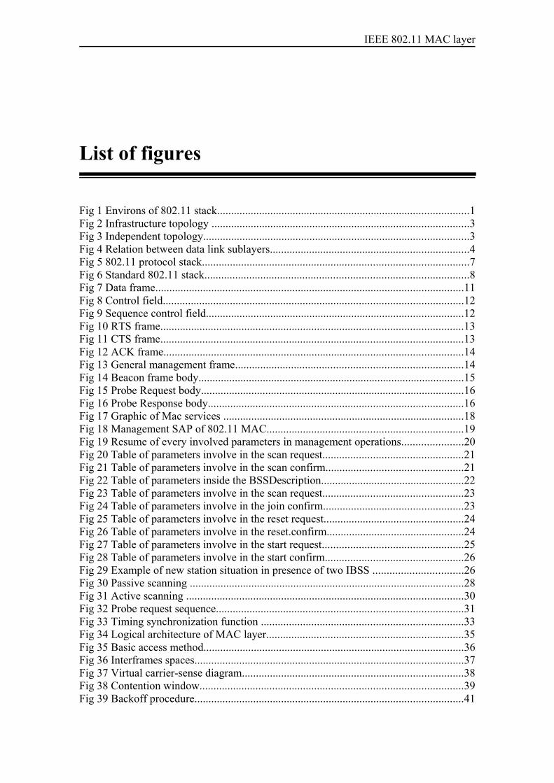
The 802.11 protocol provides the core framing operations and the interaction with awired network backbone. The framework of the protocol stack is showed in the nextfigure and is a good starting point.
IEEE 802.02 LLC
OSI layer 1PHY
OSI layer 2Data Link
MAC
PHY
IEEE802.11
Fig 1 Environs of 802.11 stack.
1
IEEE 802.11 MAC layer
The standard 802.11 must treat with many difficult because of the type of medium overthe communications are achieving, unlike Ethernet networks that use a more reliablemedium. Some of these issues are frequency allocation, in unlicensed frequency bandswhere the quality of the channel is changing with time-varying and asymmetricpropagation properties, and where different device are sharing the same band, thatmeans interferences and noisy medium. The security in a shared medium, where therearen’t physical boundaries with the possibility of superposition of LANs, and like thedevices could be mobile power consumption of the RF equipment is managed to lowrates of consumption.This paper approach to the initiate process of and ad hoc network that is described in thestandard and the main mechanism of medium access for this type of topology, with theintention of help at the time of decide to choose a MAC layer for a communicationsystem that could be develop in the environment of a non infrastructure network withlow overhead of control load. In the last chapter the Wimax mesh topology is going tobe compared, focus on the MAC operations.
1.1 Types topologies
IEEE 802.11 supports two basic topologies for Wireless LANs:
• Independent networks• Infrastructure networks
To understand these topologies, it’s necessary to define what basic service set (BSS) is;it’s a group of 802.11 stations communicating one with another that are under thecontrol of a unique distribution coordination function DCF, in the independentnetworks case, the geographical area where the BSS offer coverage is known as thebasic service area BSA, is similar to a cell in a cellular communication network.
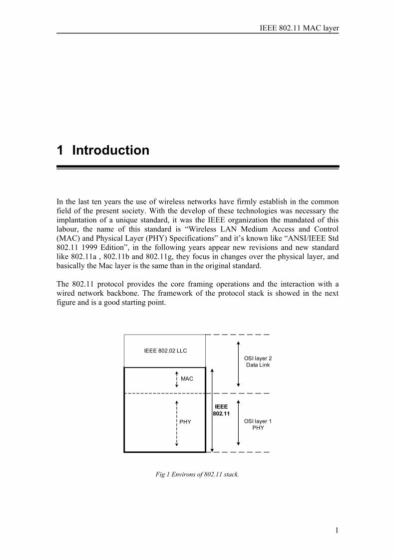
1.1.1 Infrastructure networks
It’s known like infrastructure BSS, it’s requires a specialized station known as an accesspoint (AP).The communication is taken two hops:
• First hop, the sender transmits to the access point. • Second hop, the access point transmits to the received station.
All the communications must be relayed through the access point, which give afundamental role in the network architecture; it’s costly for dynamic environments,because it must have a previous network planning. Give advantages in the problem ofsaving energy of the portable devices, and increases the coverage of the networkopposite the ad hoc networks, because the standard give the possibility of createExtended Service Ares (ESS), that is a group of access points constituting a largenetwork throughout a distribution system (DS), and with the possibility of connect toexternal network.
2
IEEE 802.11 MAC layer
Access point
Infrastrurec Basic Server Set
Station
Station
Station
Fig 2 Infrastructure topology
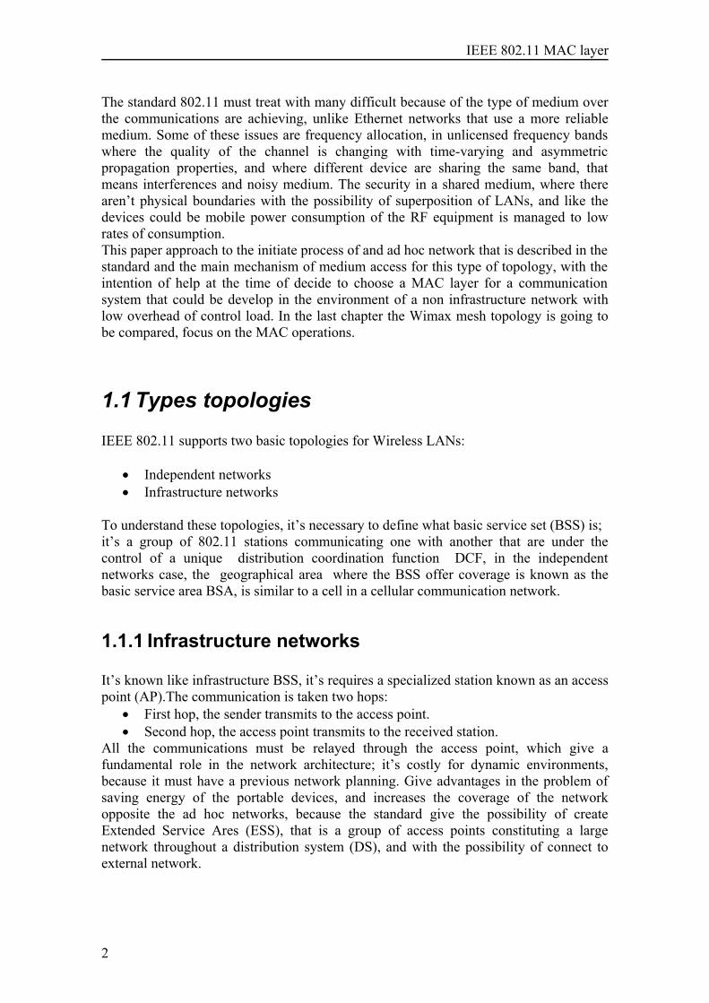
1.1.2 IBSS or Ad hoc networks
A group of wireless stations that communicate directly to exchange information in apeer to peer mode, without any coordinator, timing is controlled in a distributed manner.The coverage area that ad hoc network provide is limited, and in general is not connectto any large network. In the standard there isn’t a limit for the number of devices thatare allowed at the some time, but the throughput decrease with the amount of stations.There is not a mechanism for a rely function in an IBSS the problem of the hidden nodecan cause impossibility of communication between some stations, but this would betreat in a proximate chapter. The direct communication between the stations provide aincrease of the network capacity, but oblige a the stations to maintain relationships withall the other mobile stations. Typically this topology is used for short lived networks forspecific purpose like occasional meetings.
Station
IBSS Independent Basic Server Set
Station
Station
Fig 3 Independent topology
.
3
IEEE 802.11 MAC layer
1.2 Logical Link Control LCC
The target of LCC is to exchange data between LAN’s users using a 802-based MAC.The main features of LCC, as known like the IEEE standard 802.2 can be resumed inthe next ideas.
LLC is independent of:• Topology• Transmission medium• MAC Type
LCC provides:• Data link control• Addressing
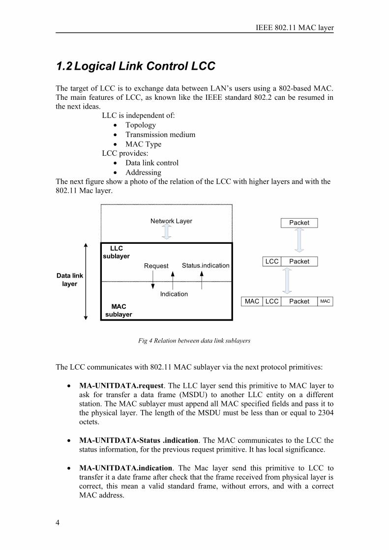
The next figure show a photo of the relation of the LCC with higher layers and with the802.11 Mac layer.
MACsublayer
Data link layer
Network Layer
LLCsublayer
Request
Indication
Status.indication
Packet
PacketLCC
MAC PacketLCC MAC
Fig 4 Relation between data link sublayers
The LCC communicates with 802.11 MAC sublayer via the next protocol primitives:
• MA-UNITDATA.request. The LLC layer send this primitive to MAC layer toask for transfer a data frame (MSDU) to another LLC entity on a differentstation. The MAC sublayer must append all MAC specified fields and pass it tothe physical layer. The length of the MSDU must be less than or equal to 2304octets.
• MA-UNITDATA-Status .indication. The MAC communicates to the LCC thestatus information, for the previous request primitive. It has local significance.
• MA-UNITDATA.indication. The Mac layer send this primitive to LCC totransfer it a date frame after check that the frame received from physical layer iscorrect, this mean a valid standard frame, without errors, and with a correctMAC address.
4
IEEE 802.11 MAC layer
1.2.1 IEEE 802.2 LLC services
The services afford the communication between peer LLC entities, one in the sourcestation and the other in the end station. The LLC provides three types of services for thenetwork layer Protocol:
• Unreliable Unacknowledge connectionless service• Reliable Connection-oriented service• Reliable Acknowledged connectionless service
1.2.1.1 Unacknowledge connectionless service
Unacknowledge connectionless service use datagram, without establishment of a logicalconnection with the distant station , without any error control or flow controlmechanisms, this service sends and receivers LLC PDUs without acknowledgement ofdelivered and data link layer connection, the reliability delivery is given by a higherlayer that assure the delivery. The advantages are:
• When is not necessary to have information of the successful delivery of the data,such as applications involving the periodic sampling of data sources, forexample monitoring sensors. With this service we are free of overhead ofconnection establishment and maintenance.
• When a higher layer protocol provides the necessary error control, flow controland reliability, it would be inefficient to duplicate them in the LCC
1.2.1.2 Connection-oriented service
The connection-oriented service establishes a logical connection between two peerLLCs that provides error control and flow control. The mechanism has three steps,connection establishment, data transfer, and connection termination.The used error control mechanism is the ARQ (Automatic repeat request), ARQ treatswith two different errors: Lost PDU and Damaged PDU. The general performance of ARQ is:
a. The transmitter sends the frame.b. When the frame is in the receiver, the station checks whether there are any errors
in the frame using a Cyclic Redundancy Check (CRC).c. The receiver send one acknowledge or a negative acknowledge depend whether
the result of CRC.d. The transmitter will retransmit the frame if receive a negative ACK or doesn’t
receive any ACK.LLC could use two different ARQ:• Continuous ARQ
The station transmits frames continuous until a error occurs, when thestation must retransmit could retransmit only the error frame, this is selectiverepeat technique or retransmit every frame after the error, go-back-ntechnique.
5
IEEE 802.11 MAC layer
• Stop and wait ARQ The sending station transmits a frame and then stops waiting for a
acknowledged from the receiver. Then if the ACK is positive could transmitthe next frame or if the ACK is negative must retransmit the frame.
1.2.1.3 Acknowledged connectionless service
The different with unacknowledged connectionless service, it’s that the receiver stationsconfirm successful delivery of datagram, and the error and flow control is handedthrough ARQ method, stop and wait. The advantages are in process control andautomated factory environments and time-critical alarm or emergency control signalsare the scenarios where acknowledged connectionless service distinguishes because thedelivery is assured and is not necessary to wait for a connection to be established.
6
IEEE 802.11 MAC layer
1.3 IEEE 802.11 reference model
Phy SAP
PMD SAP
Mac SAP
PLCP
PMD
MAC
MAC layer Management
PHY layer Mangement
MAC MIB
PHY MIB
SME
MLME SAP
PLME SAP
MLME PLME SAP
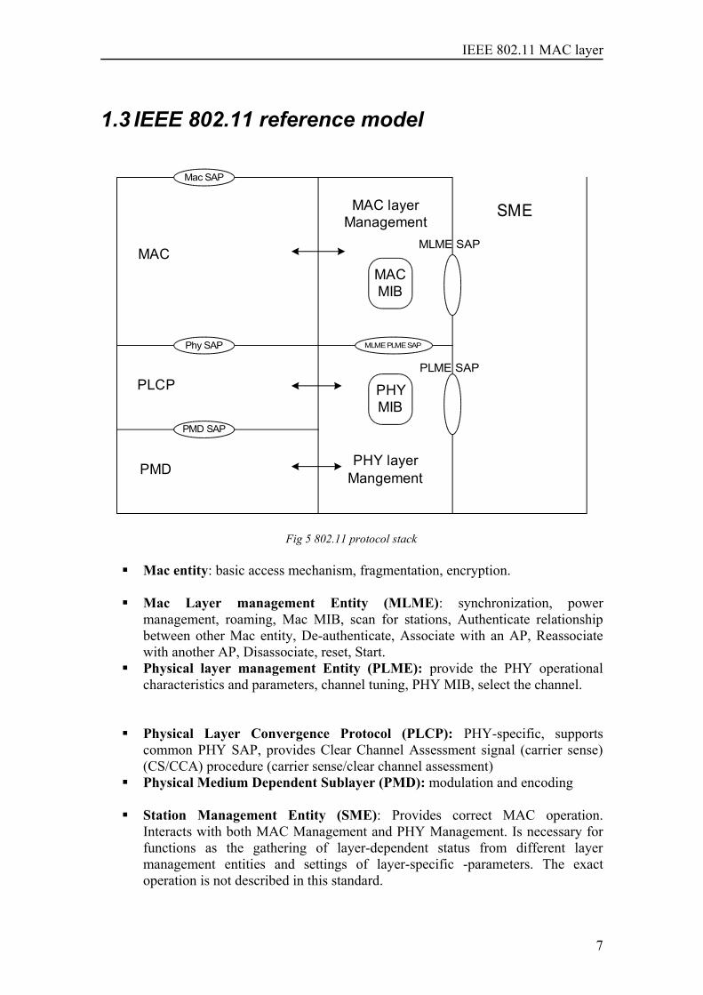
Fig 5 802.11 protocol stack
Mac entity: basic access mechanism, fragmentation, encryption.
Mac Layer management Entity (MLME): synchronization, powermanagement, roaming, Mac MIB, scan for stations, Authenticate relationshipbetween other Mac entity, De-authenticate, Associate with an AP, Reassociatewith another AP, Disassociate, reset, Start.Physical layer management Entity (PLME): provide the PHY operationalcharacteristics and parameters, channel tuning, PHY MIB, select the channel.
Physical Layer Convergence Protocol (PLCP): PHY-specific, supportscommon PHY SAP, provides Clear Channel Assessment signal (carrier sense)(CS/CCA) procedure (carrier sense/clear channel assessment)Physical Medium Dependent Sublayer (PMD): modulation and encoding
Station Management Entity (SME): Provides correct MAC operation.Interacts with both MAC Management and PHY Management. Is necessary forfunctions as the gathering of layer-dependent status from different layermanagement entities and settings of layer-specific -parameters. The exactoperation is not described in this standard.
7
IEEE 802.11 MAC layer
Management Information Base (MIB): it store information about the ongoingnetwork characteristics.
The interfaces drawing with double arrows are not describing in this standard. Mac-MLME, PHY- PLME
1.4 IEEE 802.11 Physical Layer
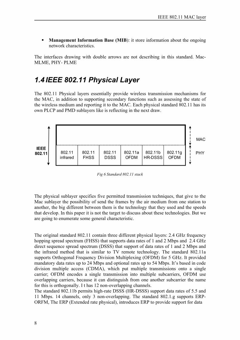
The 802.11 Physical layers essentially provide wireless transmission mechanisms forthe MAC, in addition to supporting secondary functions such as assessing the state ofthe wireless medium and reporting it to the MAC. Each physical standard 802.11 has itsown PLCP and PMD sublayers like is reflecting in the next draw.
MAC
PHYIEEE
802.11 802.11infrared
802.11FHSS
802.11DSSS
802.11aOFDM
802.11bHR-DSSS
802.11gOFDM
Fig 6 Standard 802.11 stack
The physical sublayer specifies five permitted transmission techniques, that give to theMac sublayer the possibility of send the frames by the air medium from one station toanother, the big different between them is the technology that they used and the speedsthat develop. In this paper it is not the target to discuss about these technologies. But weare going to enumerate some general characteristic.
The original standard 802.11 contain three different physical layers: 2.4 GHz frequencyhopping spread spectrum (FHSS) that supports data rates of 1 and 2 Mbps and 2.4 GHzdirect sequence spread spectrum (DSSS) that support of data rates of 1 and 2 Mbps andthe infrared method that is similar to TV remote technology. The standard 802.11asupports Orthogonal Frequency Division Multiplexing (OFDM) for 5 GHz. It providedmandatory data rates up to 24 Mbps and optional rates up to 54 Mbps. It’s based in codedivision multiple access (CDMA), which put multiple transmissions onto a singlecarrier; OFDM encodes a single transmission into multiple subcarriers, OFDM useoverlapping carriers, because it can distinguish from one another subcarrier the namefor this is orthogonally. I t has 12 non-overlapping channels.The standard 802.11b permits high-rate DSSS (HR-DSSS) support data rates of 5.5 and11 Mbps. 14 channels, only 3 non-overlapping. The standard 802.1.g supports ERP-ORFM, The ERP (Extended rate physical), introduces ERP to provide support for data
8
IEEE 802.11 MAC layer
rates up to 54 Mbps in the 2.4 GHz band. It has 4 channels, only 3 non-overlapping. Itwas an attempt to combine the best of both 802.11a and 802.11b.
1.4.1 Physical Sublayers
PLCP Physical Layer Convergence ProcedureIs essentially a handshaking layer that enables MAC protocol data units (MPDUs) to betransferred between MAC stations over the PMD, adapts the capabilities PMD systemto the PHY service.
It’s has data primitives that provide the interface for the transfer of data octets betweenthe MAC and the PMD, a method of mapping the IEEE 802.11 MPDUs into a framingformat suitable for sending and receiving data through the wireless medium.
The most important mechanism in this sublayer is carrier sense/clear channelassessment (CS/CCA) procedure; this procedure detects the start of a signal from adifferent station and determines whether the channel is clear for transmitting.
PMD Physical Medium DependantThe PLCP converts the frame into a binary bit stream and passes this bit stream to thePMD sublayer, and then the PMD provide a method of transmitting and receiving data,by the wireless medium between two stations.
1.4.2 Radio Spectrum
Radio spectrum allocation is rigorously controlled by regulatory authorities throughlicensing processes. European allocation is performed by the European Radiocommunications Office (ERO). Other allocation work is done by the InternationalTelecommunications Union (ITU). The standard 802.11 is a protocol that operate onwhat is known as unlicensed spectrum, where is not require the operator to obtain anexclusive license to transmit on a given frequency in a given region, these bands areopen for anyone to transmit within certain technical parameters such as power limits.
To prevent overlapping uses of the radio waves, frequency is allocated in bands, whichare simply ranges of frequencies available to specified applications. The Unlicensedbands that use wireless are two:
• S-Band ISM 2.4-2.5 GHz • C-Band ISM 5.725 5.875 GHz
9
IEEE 802.11 MAC layer
1.5 IEEE 802.11 Medium Access Control “MACsublayer”
The primary service of the 802.11 standard is to deliver MAC service data units(MSDUs) between peer logical link controls (LLCs).The IEEE 802.11 MAC layerprovides three principal operations in support of LCC sublayer:
• Joining a wireless network.• Provide Access control functions to the wireless sharing-medium such as:
AddressingAccess coordination, controls the transmission of user data into the air.Frame check sequence generation and checking LLC PDU delimiting
• Providing authentication and privacy
Furthermore 802.11 MAC perform tasks with the physical layers of the standard IEEE802.11, the MAC rides on every physical layer and permits the interoperate of differenttransmission speeds. Different physical layers may provide different transmissionspeeds, all of which are supposed to interoperate.
In this paper we are going to omit talk about authentication and privacy issues, for focusin joining and providing access issues in the next chapters, there is a chapter where it’sshowed a brief description of the frames of this standard that will be used along theexplications.
In the fifth chapter, it is added a comparison between the Standard 802.11 MAC layer inad-hoc networks and the IEEE Standard 802.16 MAC Layer in Distributed MeshNetwork. This comparison is realized with the help of the thesis “Investigation of IEEEstandard 802.16 Medium Access Control (MAC) layer in Distributed Mesh Networksand comparison with IEEE 802.16 ad-hoc networks” written by Pedro Francisco RoblesRico.
10
IEEE 802.11 MAC layer
2 Types of frames
The specification determines three types of frames: data frames, control frames andmanagement frames. The next issues are going to show the specify frames forIndependent BSS.
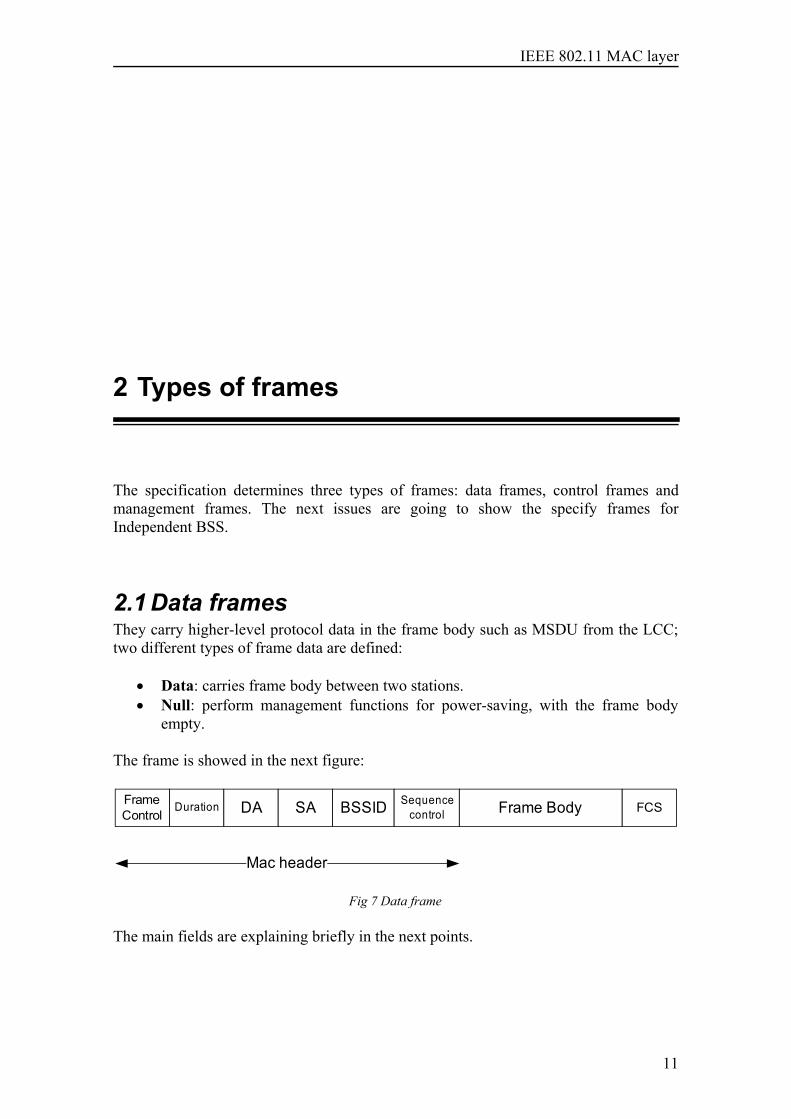
2.1 Data framesThey carry higher-level protocol data in the frame body such as MSDU from the LCC;two different types of frame data are defined:
• Data: carries frame body between two stations.• Null: perform management functions for power-saving, with the frame body
empty.
The frame is showed in the next figure:
FrameControl
Duration DA SA BSSID Sequence control Frame Body FCS
Mac header
Fig 7 Data frame
The main fields are explaining briefly in the next points.
11
IEEE 802.11 MAC layer
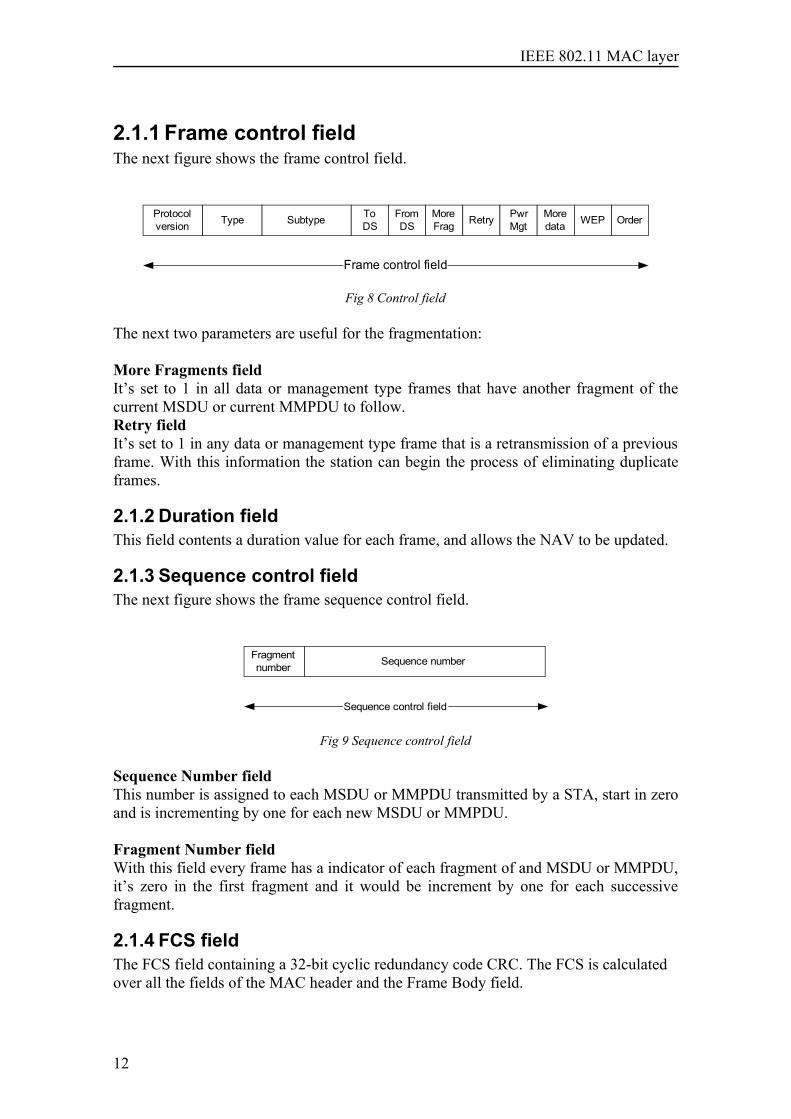
2.1.1 Frame control field The next figure shows the frame control field.
Protocol version Type Subtype To
DSFrom DS
More Frag Retry
Frame control field
Pwr Mgt
More data WEP Order
Fig 8 Control field
The next two parameters are useful for the fragmentation:
More Fragments fieldIt’s set to 1 in all data or management type frames that have another fragment of thecurrent MSDU or current MMPDU to follow.Retry fieldIt’s set to 1 in any data or management type frame that is a retransmission of a previousframe. With this information the station can begin the process of eliminating duplicateframes.
2.1.2 Duration fieldThis field contents a duration value for each frame, and allows the NAV to be updated.
2.1.3 Sequence control field The next figure shows the frame sequence control field.
Fragment number Sequence number
Sequence control field
Fig 9 Sequence control field
Sequence Number fieldThis number is assigned to each MSDU or MMPDU transmitted by a STA, start in zeroand is incrementing by one for each new MSDU or MMPDU.
Fragment Number fieldWith this field every frame has a indicator of each fragment of and MSDU or MMPDU,it’s zero in the first fragment and it would be increment by one for each successivefragment.
2.1.4 FCS fieldThe FCS field containing a 32-bit cyclic redundancy code CRC. The FCS is calculatedover all the fields of the MAC header and the Frame Body field.
12
IEEE 802.11 MAC layer
2.2 Control Frames
This type of frames provides functionality to perform the deliver of the frames. Withinthe IBSS networks only three control frames are used:
• RTS• CTS• ACK
In the other topology, infrastructure BSS:• PS-Poll
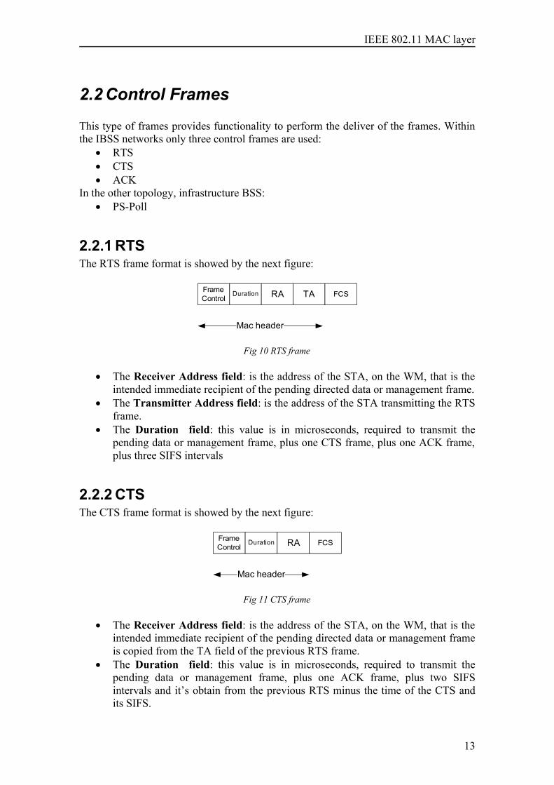
2.2.1 RTSThe RTS frame format is showed by the next figure:
FrameControl
Duration RA TA FCS
Mac header
Fig 10 RTS frame
• The Receiver Address field: is the address of the STA, on the WM, that is theintended immediate recipient of the pending directed data or management frame.
• The Transmitter Address field: is the address of the STA transmitting the RTSframe.
• The Duration field: this value is in microseconds, required to transmit thepending data or management frame, plus one CTS frame, plus one ACK frame,plus three SIFS intervals
2.2.2 CTSThe CTS frame format is showed by the next figure:
FrameControl
Duration RA FCS
Mac header
Fig 11 CTS frame
• The Receiver Address field: is the address of the STA, on the WM, that is theintended immediate recipient of the pending directed data or management frameis copied from the TA field of the previous RTS frame.
• The Duration field: this value is in microseconds, required to transmit thepending data or management frame, plus one ACK frame, plus two SIFSintervals and it’s obtain from the previous RTS minus the time of the CTS andits SIFS.
13
IEEE 802.11 MAC layer
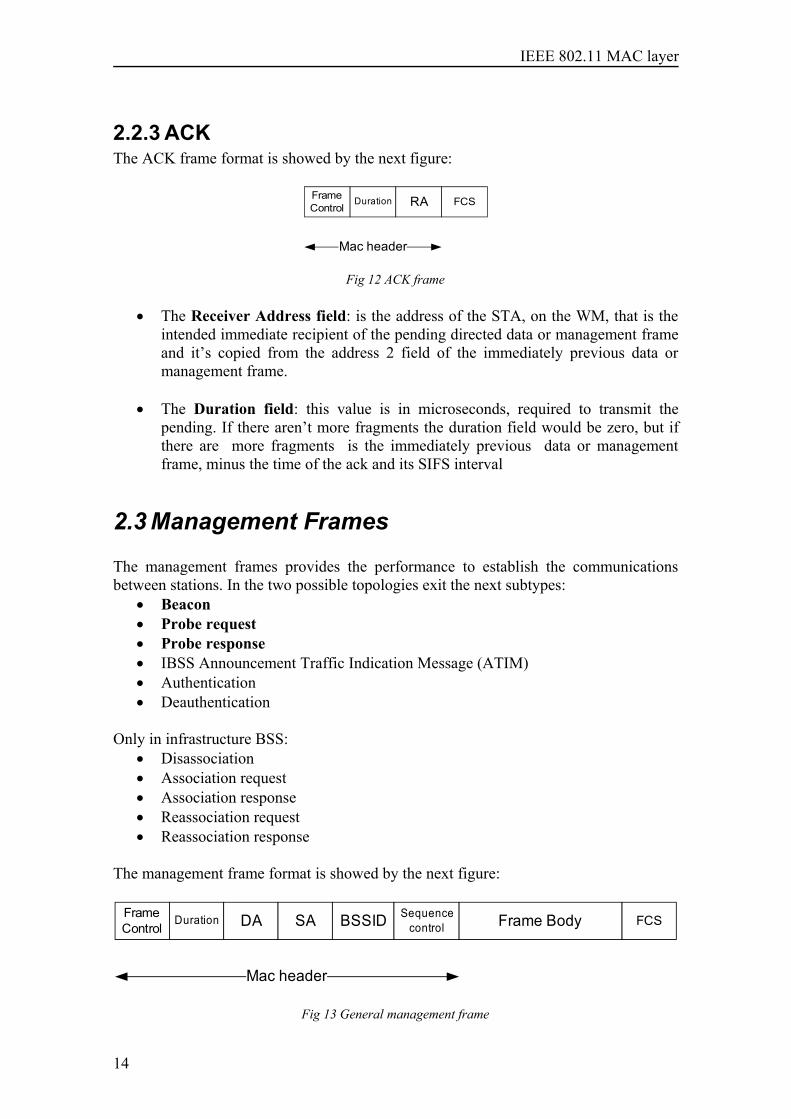
2.2.3 ACKThe ACK frame format is showed by the next figure:
FrameControl
Duration RA FCS
Mac header
Fig 12 ACK frame
• The Receiver Address field: is the address of the STA, on the WM, that is theintended immediate recipient of the pending directed data or management frameand it’s copied from the address 2 field of the immediately previous data ormanagement frame.
• The Duration field: this value is in microseconds, required to transmit thepending. If there aren’t more fragments the duration field would be zero, but ifthere are more fragments is the immediately previous data or managementframe, minus the time of the ack and its SIFS interval
2.3 Management Frames
The management frames provides the performance to establish the communicationsbetween stations. In the two possible topologies exit the next subtypes:
• Beacon• Probe request• Probe response• IBSS Announcement Traffic Indication Message (ATIM)• Authentication• Deauthentication
Only in infrastructure BSS:• Disassociation• Association request• Association response• Reassociation request • Reassociation response
The management frame format is showed by the next figure:
FrameControl
Duration DA SA BSSID Sequence control Frame Body FCS
Mac header
Fig 13 General management frame
14
IEEE 802.11 MAC layer
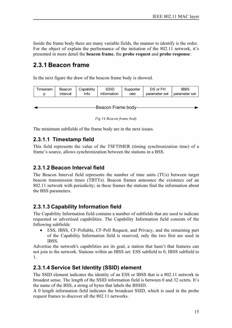
Inside the frame body there are many variable fields, the manner to identify is the order.For the object of explain the performance of the initiation of the 802.11 network, it’spresented in more detail the beacon frame, the probe request and probe response:
2.3.1 Beacon frame
In the next figure the draw of the beacon frame body is showed.
Timestamp
Beacon interval
Capability Info
SSID information
Supporter rate
DS or FH parameter set
IBBS parameter set
Beacon Frame body
Fig 14 Beacon frame body
The minimum subfields of the frame body are in the next issues.
2.3.1.1 Timestamp fieldThis field represents the value of the TSFTIMER (timing synchronization time) of aframe’s source, allows synchronization between the stations in a BSS.
2.3.1.2 Beacon Interval fieldThe Beacon Interval field represents the number of time units (TUs) between targetbeacon transmission times (TBTTs). Beacon frames announce the existence oaf an802.11 network with periodicity; in these frames the stations find the information aboutthe BSS parameters.
2.3.1.3 Capability Information fieldThe Capability Information field contains a number of subfields that are used to indicaterequested or advertised capabilities. The Capability Information field consists of thefollowing subfields:
• ESS, IBSS, CF-Pollable, CF-Poll Request, and Privacy, and the remaining partof the Capability Information field is reserved, only the two first are used inIBSS.
Advertise the network's capabilities are its goal, a station that hasn’t that features cannot join to the network. Stations within an IBSS set: ESS subfield to 0, IBSS subfield to1.
2.3.1.4 Service Set Identity (SSID) elementThe SSID element indicates the identity of an ESS or IBSS that is a 802.11 network inbroadest sense. The length of the SSID information field is between 0 and 32 octets. It’sthe name of the BSS, a string of bytes that labels the BSSID. A 0 length information field indicates the broadcast SSID, which is used in the proberequest frames to discover all the 802.11 networks.
15
IEEE 802.11 MAC layer
2.3.1.5 Supported Rates elementThe Supported Rates element specifies the rates in the Operational Rate Set as describedin the MLME-Join.request and MLME-Start.request primitives. The information field isencoded as 1 to 8 octets where each octet describes a single supported rate in units of500 kbit/s. Some of the rates are mandatory if you want to join to the BSS, and must besupported by the station.
2.3.1.6 IBSS Parameter Set elementThe IBSS Parameter Set element only contains one parameter:
• ATIM Window parameter: It indicates the number of time units (TUs) betweenATIM frames in an IBSS, and used only in IBSS Beacon frames
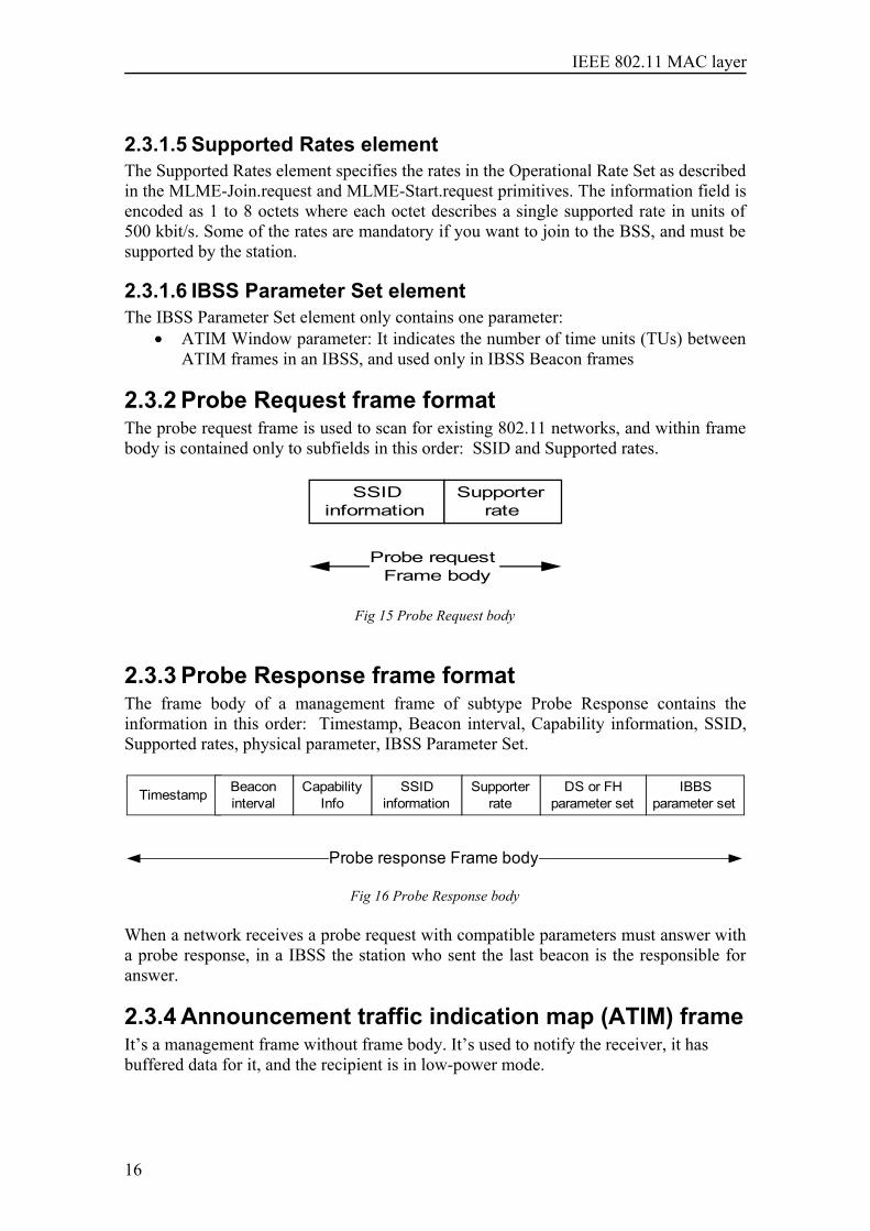
2.3.2 Probe Request frame formatThe probe request frame is used to scan for existing 802.11 networks, and within framebody is contained only to subfields in this order: SSID and Supported rates.
SSID information
Supporter rate
Probe request Frame body
Fig 15 Probe Request body
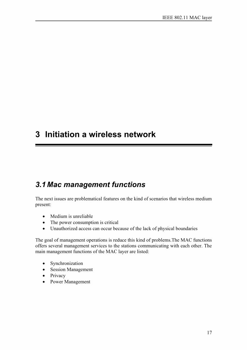
2.3.3 Probe Response frame formatThe frame body of a management frame of subtype Probe Response contains theinformation in this order: Timestamp, Beacon interval, Capability information, SSID,Supported rates, physical parameter, IBSS Parameter Set.
Timestamp Beacon interval
Capability Info
SSID information
Supporter rate
DS or FH parameter set
IBBS parameter set
Probe response Frame body
Fig 16 Probe Response body
When a network receives a probe request with compatible parameters must answer witha probe response, in a IBSS the station who sent the last beacon is the responsible foranswer.
2.3.4 Announcement traffic indication map (ATIM) frameIt’s a management frame without frame body. It’s used to notify the receiver, it hasbuffered data for it, and the recipient is in low-power mode.
16
IEEE 802.11 MAC layer
3 Initiation a wireless network
3.1 Mac management functions
The next issues are problematical features on the kind of scenarios that wireless mediumpresent:
• Medium is unreliable• The power consumption is critical• Unauthorized access can occur because of the lack of physical boundaries
The goal of management operations is reduce this kind of problems.The MAC functionsoffers several management services to the stations communicating with each other. Themain management functions of the MAC layer are listed:
• Synchronization • Session Management• Privacy• Power Management
17
IEEE 802.11 MAC layer
Session management refers to such association and authentication of the stations,address filtering upon data delivery. The privacy is held up by the encryption algorithmsand is necessary because the wireless medium is not very reliable against otherslisteners. With the Power management it’s extending the live of the batteries. In thischapter we are going to talk about the synchronization between stations clocks, and forthis is necessary to initiating the station, scanning the BSS’s joining and later maintainsthe synchronization. The Privacy and the power management are not mandatory in anindependent BSS, and only the address filtering of the session management.
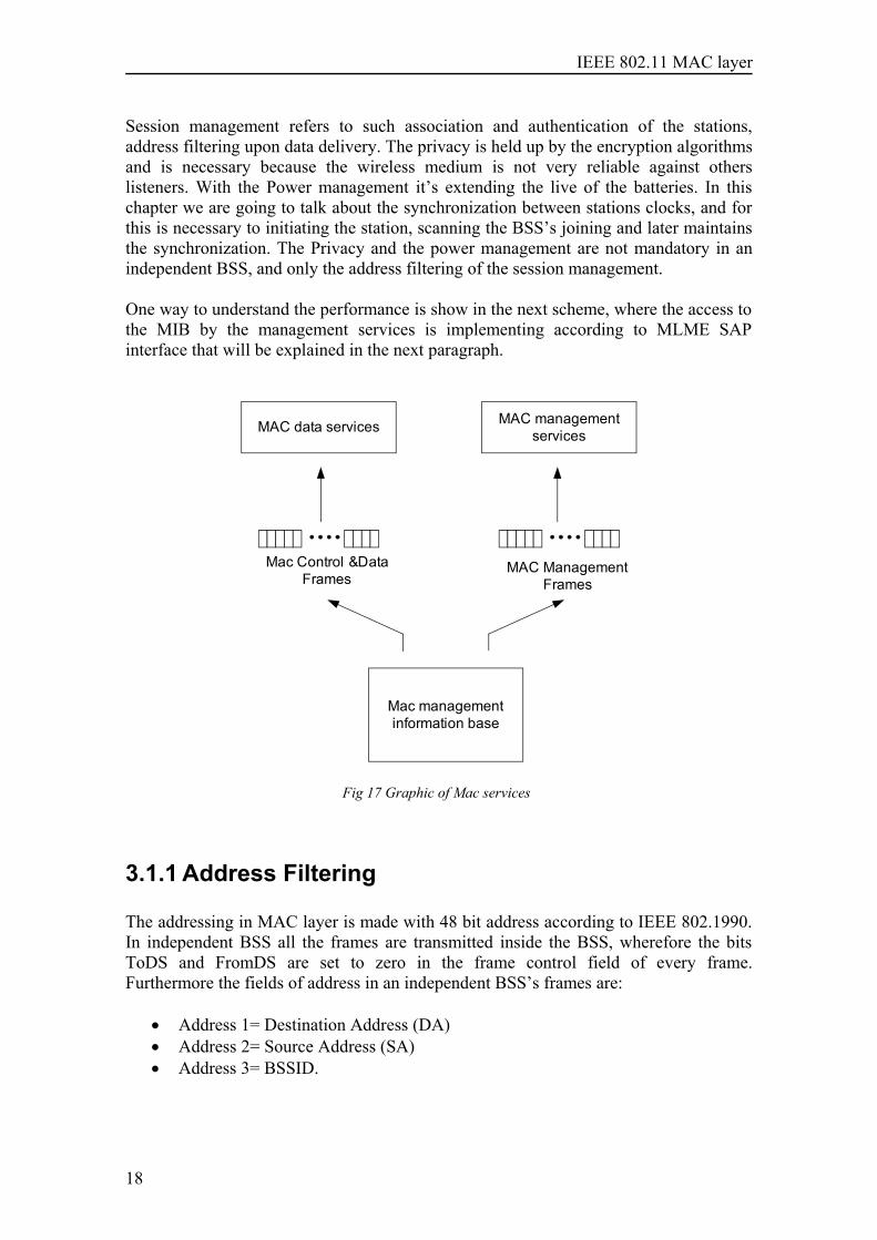
One way to understand the performance is show in the next scheme, where the access tothe MIB by the management services is implementing according to MLME SAPinterface that will be explained in the next paragraph.
MAC data services MAC management services
Mac management information base
MAC ManagementFrames
Mac Control &DataFrames
Fig 17 Graphic of Mac services
3.1.1 Address Filtering
The addressing in MAC layer is made with 48 bit address according to IEEE 802.1990.In independent BSS all the frames are transmitted inside the BSS, wherefore the bitsToDS and FromDS are set to zero in the frame control field of every frame.Furthermore the fields of address in an independent BSS’s frames are:
• Address 1= Destination Address (DA)• Address 2= Source Address (SA)• Address 3= BSSID.
18
IEEE 802.11 MAC layer
This last is the Basic service set identifier , that’s a basic service set identifier, in aIndependent BSS all the frames carry the same BSSID and must be created, generate46 random bits plus two special bits : The U/L bit, with a one that’s mean localaddress and I/G bit with a cero that’s mean individual address. The all-1s BSSID isthe broadcast BSSID.
The address filtering mechanism in the IEEE 802.11 the receiver must examine morethan the destination address to make a correct receiver decisions. In the samelocalization and the same channel, could be, that more than one station weretransmitting, the receiver’s station must check more than the destination address, for theproperly performance of the Mac layer, in the IBSS are three different directions. Withthe BSSID the receiver can discard the frames sent from another BSS, this is veryimportant for the no saturation with the broadcast messages.
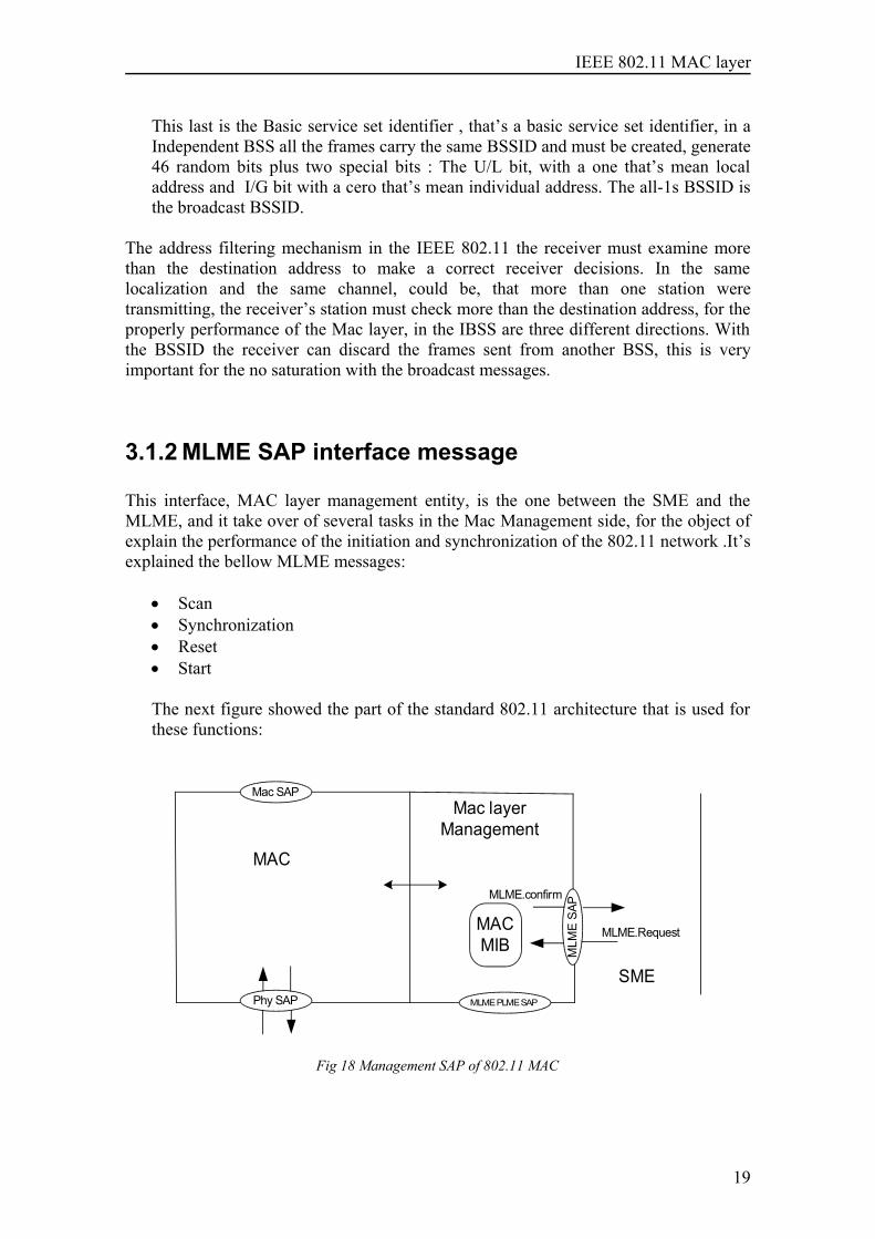
3.1.2 MLME SAP interface message
This interface, MAC layer management entity, is the one between the SME and theMLME, and it take over of several tasks in the Mac Management side, for the object ofexplain the performance of the initiation and synchronization of the 802.11 network .It’sexplained the bellow MLME messages:
• Scan• Synchronization• Reset• Start
The next figure showed the part of the standard 802.11 architecture that is used forthese functions:
Phy SAP
MLM
E SA
P
Mac SAP
MAC
Mac layer Management
MAC MIB
SMEMLME PLME SAP
MLME.Request
MLME.confirm
Fig 18 Management SAP of 802.11 MAC
19
IEEE 802.11 MAC layer
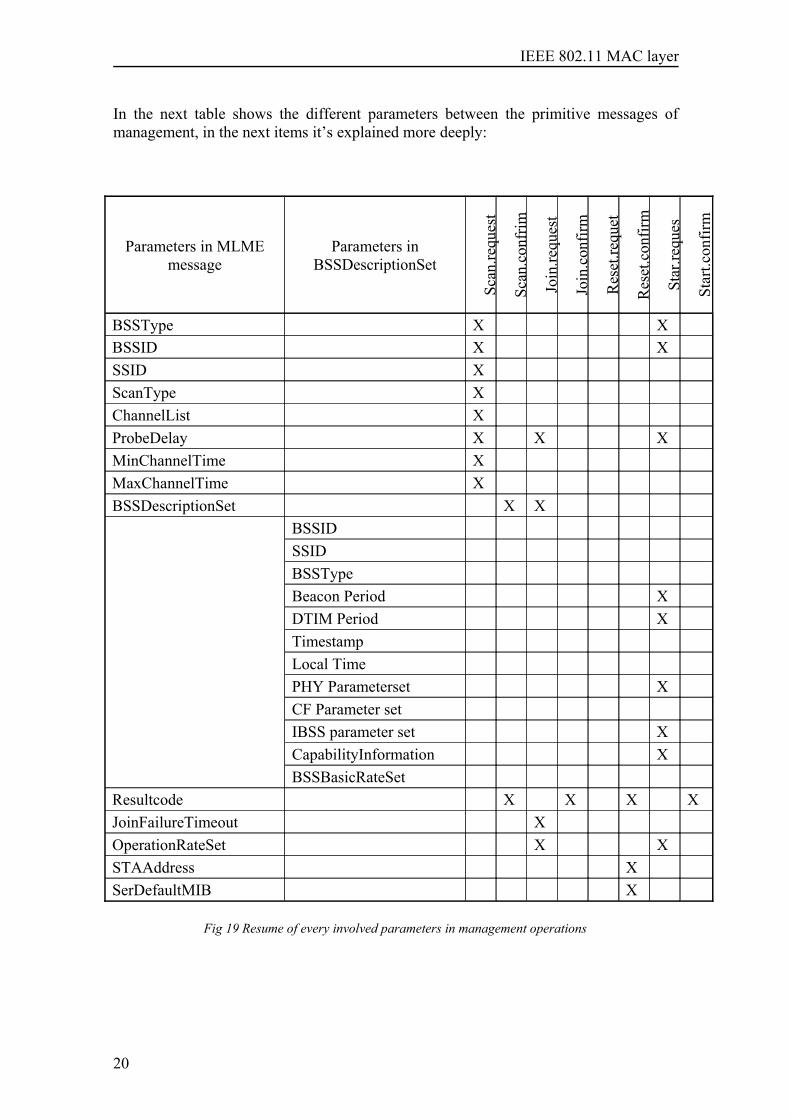
In the next table shows the different parameters between the primitive messages ofmanagement, in the next items it’s explained more deeply:
Parameters in MLMEmessage
Parameters inBSSDescriptionSet
Scan
.requ
est
Scan
.con
frim
Join
.requ
est
Join
.con
firm
Res
et.re
quet
Res
et.c
onfir
m
Star
.requ
es
Star
t.con
firm
BSSType X XBSSID X XSSID XScanType XChannelList XProbeDelay X X XMinChannelTime XMaxChannelTime XBSSDescriptionSet X X
BSSIDSSIDBSSTypeBeacon Period XDTIM Period XTimestampLocal TimePHY Parameterset XCF Parameter setIBSS parameter set XCapabilityInformation XBSSBasicRateSet
Resultcode X X X XJoinFailureTimeout XOperationRateSet X XSTAAddress XSerDefaultMIB X
Fig 19 Resume of every involved parameters in management operations
20
IEEE 802.11 MAC layer
3.1.2.1 ScanThe next two messages support the mechanism of determining the characteristics of theavailable BSSs.
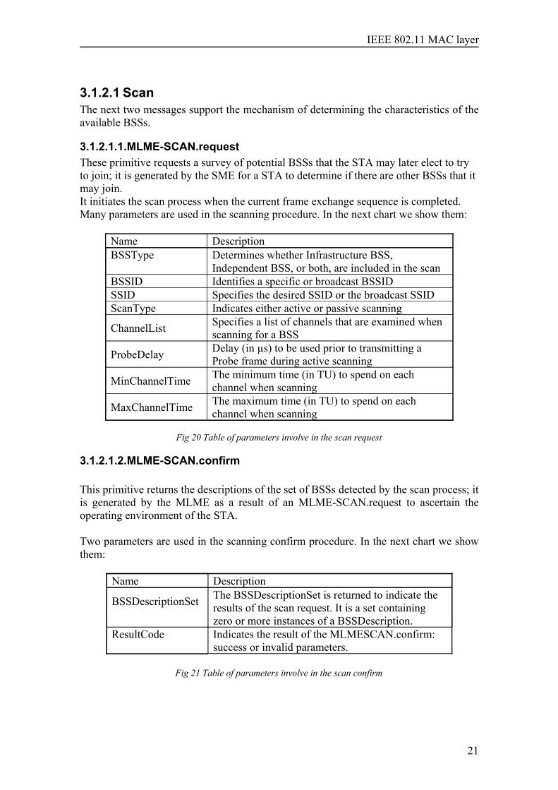
3.1.2.1.1.MLME-SCAN.requestThese primitive requests a survey of potential BSSs that the STA may later elect to tryto join; it is generated by the SME for a STA to determine if there are other BSSs that itmay join.It initiates the scan process when the current frame exchange sequence is completed.Many parameters are used in the scanning procedure. In the next chart we show them:
Name DescriptionBSSType Determines whether Infrastructure BSS,
Independent BSS, or both, are included in the scanBSSID Identifies a specific or broadcast BSSIDSSID Specifies the desired SSID or the broadcast SSIDScanType Indicates either active or passive scanning
ChannelList Specifies a list of channels that are examined whenscanning for a BSS
ProbeDelay Delay (in µs) to be used prior to transmitting aProbe frame during active scanning
MinChannelTime The minimum time (in TU) to spend on eachchannel when scanning
MaxChannelTime The maximum time (in TU) to spend on eachchannel when scanning
Fig 20 Table of parameters involve in the scan request
3.1.2.1.2.MLME-SCAN.confirm
This primitive returns the descriptions of the set of BSSs detected by the scan process; itis generated by the MLME as a result of an MLME-SCAN.request to ascertain theoperating environment of the STA.
Two parameters are used in the scanning confirm procedure. In the next chart we showthem:
Name Description
BSSDescriptionSet The BSSDescriptionSet is returned to indicate theresults of the scan request. It is a set containingzero or more instances of a BSSDescription.
ResultCode Indicates the result of the MLMESCAN.confirm:success or invalid parameters.
Fig 21 Table of parameters involve in the scan confirm
21
IEEE 802.11 MAC layer
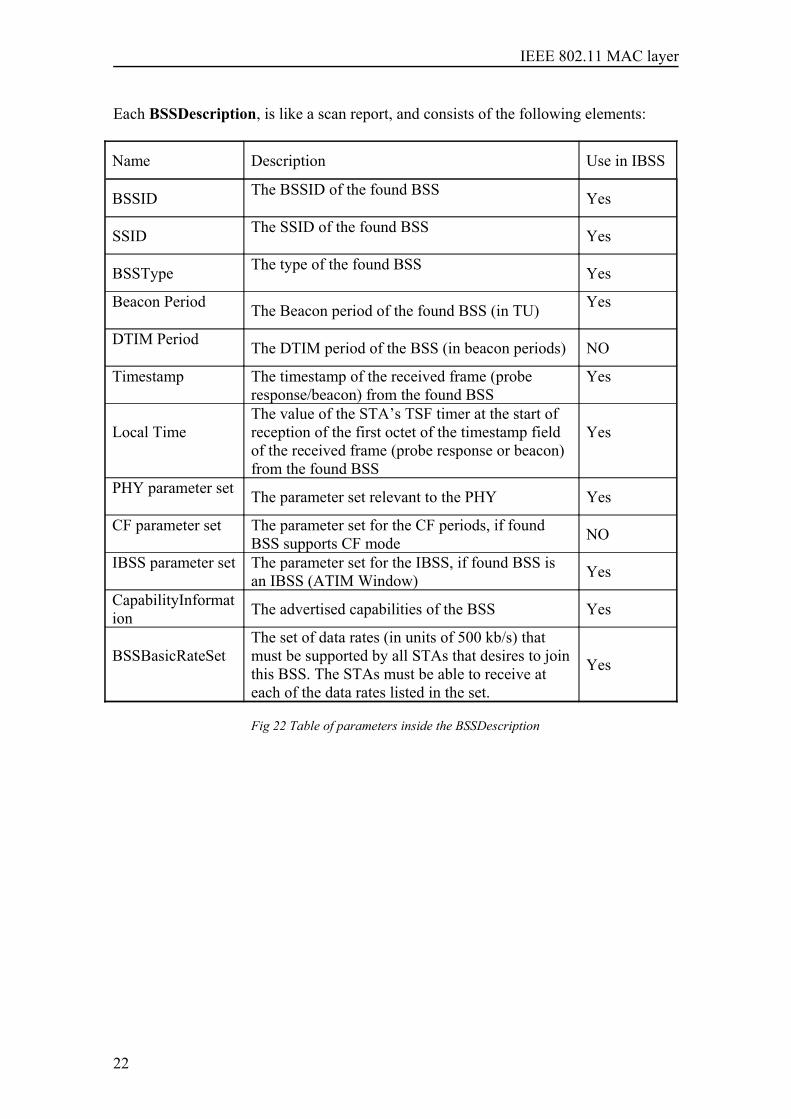
Each BSSDescription, is like a scan report, and consists of the following elements:
Name Description Use in IBSS
BSSID The BSSID of the found BSS Yes
SSID The SSID of the found BSS Yes
BSSType The type of the found BSS Yes
Beacon Period The Beacon period of the found BSS (in TU) Yes
DTIM Period The DTIM period of the BSS (in beacon periods) NO
Timestamp The timestamp of the received frame (proberesponse/beacon) from the found BSS
Yes
Local TimeThe value of the STA’s TSF timer at the start ofreception of the first octet of the timestamp fieldof the received frame (probe response or beacon)from the found BSS
Yes
PHY parameter set The parameter set relevant to the PHY Yes
CF parameter set The parameter set for the CF periods, if foundBSS supports CF mode NO
IBSS parameter set The parameter set for the IBSS, if found BSS isan IBSS (ATIM Window) Yes
CapabilityInformation The advertised capabilities of the BSS Yes
BSSBasicRateSetThe set of data rates (in units of 500 kb/s) thatmust be supported by all STAs that desires to jointhis BSS. The STAs must be able to receive ateach of the data rates listed in the set.
Yes
Fig 22 Table of parameters inside the BSSDescription
22
IEEE 802.11 MAC layer
3.1.2.2 Synchronization
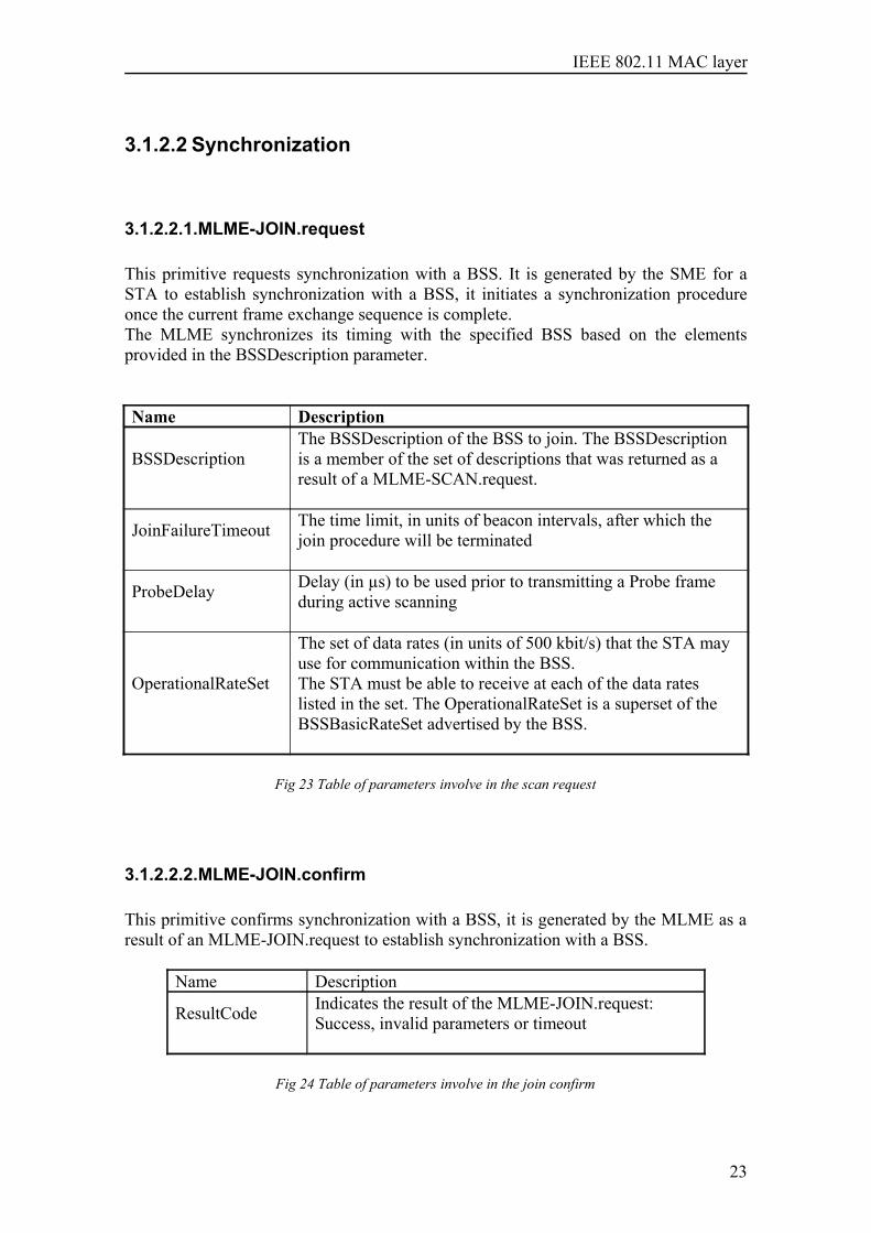
3.1.2.2.1.MLME-JOIN.request
This primitive requests synchronization with a BSS. It is generated by the SME for aSTA to establish synchronization with a BSS, it initiates a synchronization procedureonce the current frame exchange sequence is complete.The MLME synchronizes its timing with the specified BSS based on the elementsprovided in the BSSDescription parameter.
Name Description
BSSDescriptionThe BSSDescription of the BSS to join. The BSSDescriptionis a member of the set of descriptions that was returned as aresult of a MLME-SCAN.request.
JoinFailureTimeout The time limit, in units of beacon intervals, after which thejoin procedure will be terminated
ProbeDelay Delay (in µs) to be used prior to transmitting a Probe frameduring active scanning
OperationalRateSet
The set of data rates (in units of 500 kbit/s) that the STA mayuse for communication within the BSS.The STA must be able to receive at each of the data rateslisted in the set. The OperationalRateSet is a superset of theBSSBasicRateSet advertised by the BSS.
Fig 23 Table of parameters involve in the scan request
3.1.2.2.2.MLME-JOIN.confirm
This primitive confirms synchronization with a BSS, it is generated by the MLME as aresult of an MLME-JOIN.request to establish synchronization with a BSS.
Name Description
ResultCode Indicates the result of the MLME-JOIN.request:Success, invalid parameters or timeout
Fig 24 Table of parameters involve in the join confirm
23
IEEE 802.11 MAC layer
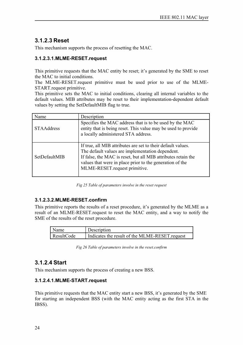
3.1.2.3 ResetThis mechanism supports the process of resetting the MAC.
3.1.2.3.1.MLME-RESET.request
This primitive requests that the MAC entity be reset; it’s generated by the SME to resetthe MAC to initial conditions.The MLME-RESET.request primitive must be used prior to use of the MLME-START.request primitive.This primitive sets the MAC to initial conditions, clearing all internal variables to thedefault values. MIB attributes may be reset to their implementation-dependent defaultvalues by setting the SetDefaultMIB flag to true.
Name Description
STAAddressSpecifies the MAC address that is to be used by the MACentity that is being reset. This value may be used to providea locally administered STA address.
SetDefaultMIB
If true, all MIB attributes are set to their default values.The default values are implementation dependent.If false, the MAC is reset, but all MIB attributes retain thevalues that were in place prior to the generation of theMLME-RESET.request primitive.
Fig 25 Table of parameters involve in the reset request
3.1.2.3.2.MLME-RESET.confirmThis primitive reports the results of a reset procedure, it’s generated by the MLME as aresult of an MLME-RESET.request to reset the MAC entity, and a way to notify theSME of the results of the reset procedure.
Name DescriptionResultCode Indicates the result of the MLME-RESET.request
Fig 26 Table of parameters involve in the reset.confirm
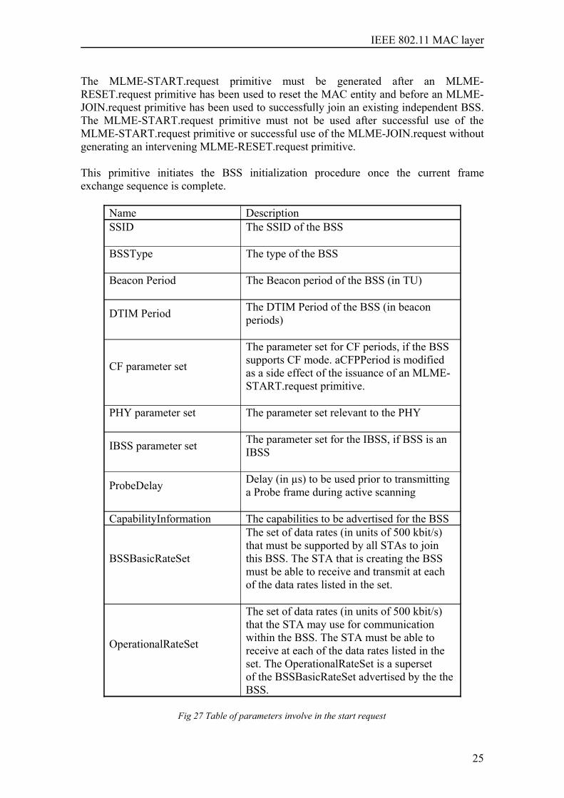
3.1.2.4 StartThis mechanism supports the process of creating a new BSS.
3.1.2.4.1.MLME-START.request
This primitive requests that the MAC entity start a new BSS, it’s generated by the SMEfor starting an independent BSS (with the MAC entity acting as the first STA in theIBSS).
24
IEEE 802.11 MAC layer
The MLME-START.request primitive must be generated after an MLME-RESET.request primitive has been used to reset the MAC entity and before an MLME-JOIN.request primitive has been used to successfully join an existing independent BSS.The MLME-START.request primitive must not be used after successful use of theMLME-START.request primitive or successful use of the MLME-JOIN.request withoutgenerating an intervening MLME-RESET.request primitive.
This primitive initiates the BSS initialization procedure once the current frameexchange sequence is complete.
Name DescriptionSSID The SSID of the BSS
BSSType The type of the BSS
Beacon Period The Beacon period of the BSS (in TU)
DTIM Period The DTIM Period of the BSS (in beaconperiods)
CF parameter set
The parameter set for CF periods, if the BSSsupports CF mode. aCFPPeriod is modifiedas a side effect of the issuance of an MLME-START.request primitive.
PHY parameter set The parameter set relevant to the PHY
IBSS parameter set The parameter set for the IBSS, if BSS is anIBSS
ProbeDelay Delay (in µs) to be used prior to transmittinga Probe frame during active scanning
CapabilityInformation The capabilities to be advertised for the BSS
BSSBasicRateSet
The set of data rates (in units of 500 kbit/s)that must be supported by all STAs to jointhis BSS. The STA that is creating the BSSmust be able to receive and transmit at eachof the data rates listed in the set.
OperationalRateSet
The set of data rates (in units of 500 kbit/s)that the STA may use for communicationwithin the BSS. The STA must be able toreceive at each of the data rates listed in theset. The OperationalRateSet is a supersetof the BSSBasicRateSet advertised by the theBSS.
Fig 27 Table of parameters involve in the start request
25
IEEE 802.11 MAC layer
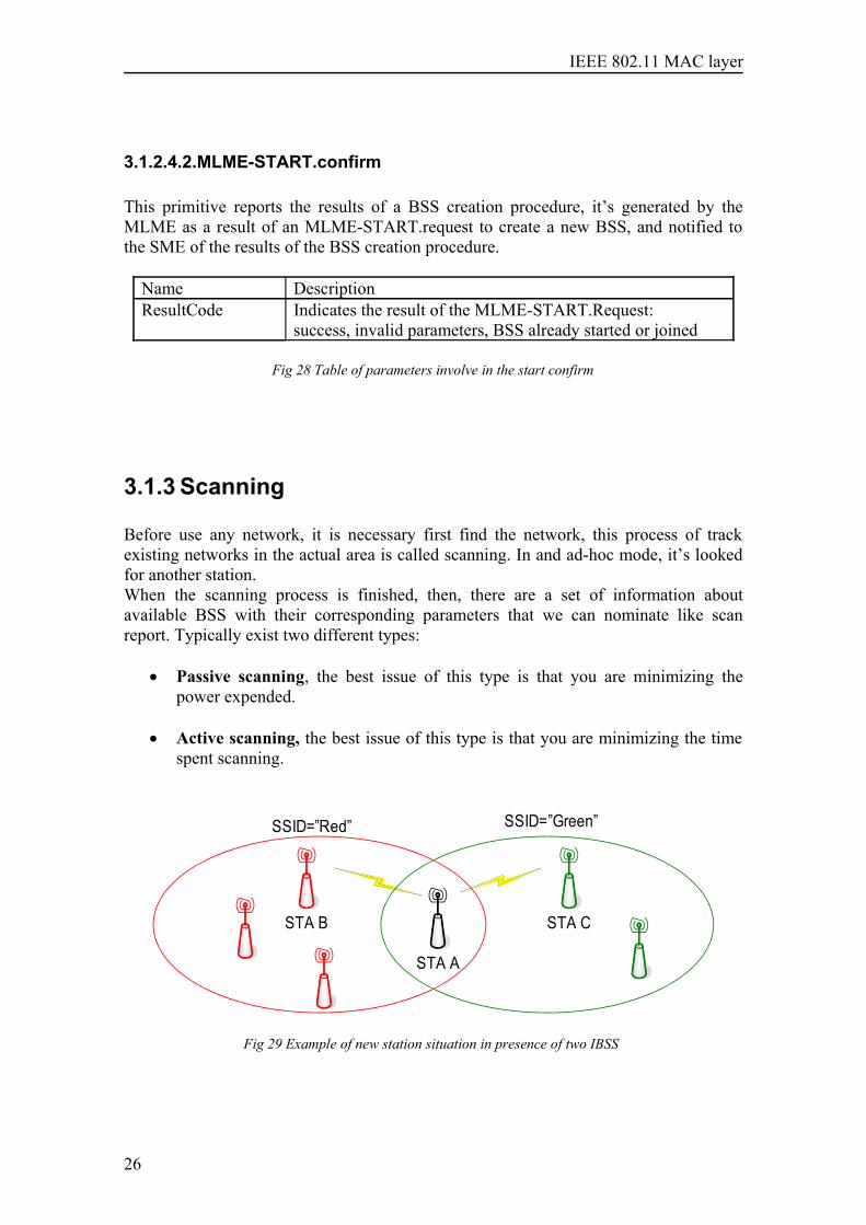
3.1.2.4.2.MLME-START.confirm
This primitive reports the results of a BSS creation procedure, it’s generated by theMLME as a result of an MLME-START.request to create a new BSS, and notified tothe SME of the results of the BSS creation procedure.
Name DescriptionResultCode Indicates the result of the MLME-START.Request:
success, invalid parameters, BSS already started or joined
Fig 28 Table of parameters involve in the start confirm
3.1.3 Scanning
Before use any network, it is necessary first find the network, this process of trackexisting networks in the actual area is called scanning. In and ad-hoc mode, it’s lookedfor another station.When the scanning process is finished, then, there are a set of information aboutavailable BSS with their corresponding parameters that we can nominate like scanreport. Typically exist two different types:
• Passive scanning, the best issue of this type is that you are minimizing thepower expended.
• Active scanning, the best issue of this type is that you are minimizing the timespent scanning.
STA B
STA A
STA C
SSID=”Red” SSID=”Green”
Fig 29 Example of new station situation in presence of two IBSS
26
IEEE 802.11 MAC layer
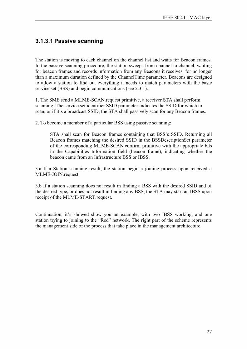
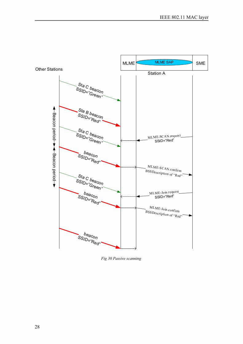
3.1.3.1 Passive scanning
The station is moving to each channel on the channel list and waits for Beacon frames.In the passive scanning procedure, the station sweeps from channel to channel, waitingfor beacon frames and records information from any Beacons it receives, for no longerthan a maximum duration defined by the ChannelTime parameter. Beacons are designedto allow a station to find out everything it needs to match parameters with the basicservice set (BSS) and begin communications (see 2.3.1).
1. The SME send a MLME-SCAN.request primitive, a receiver STA shall performscanning. The service set identifier SSID parameter indicates the SSID for which toscan, or if it’s a broadcast SSID, the STA shall passively scan for any Beacon frames.
2. To become a member of a particular BSS using passive scanning:
STA shall scan for Beacon frames containing that BSS’s SSID. Returning allBeacon frames matching the desired SSID in the BSSDescriptionSet parameterof the corresponding MLME-SCAN.confirm primitive with the appropriate bitsin the Capabilities Information field (beacon frame), indicating whether thebeacon came from an Infrastructure BSS or IBSS.
3.a If a Station scanning result, the station begin a joining process upon received aMLME-JOIN.request.
3.b If a station scanning does not result in finding a BSS with the desired SSID and ofthe desired type, or does not result in finding any BSS, the STA may start an IBSS uponreceipt of the MLME-START.request.
Continuation, it’s showed show you an example, with two IBSS working, and onestation trying to joining to the “Red” network. The right part of the scheme representsthe management side of the process that take place in the management architecture.
27
IEEE 802.11 MAC layer
MLME-SCAN.request
SSID=”Red”
Other StationsStation A
MLME-SCAN.confirm BSSDescription of “Red”
Sta B beaconSSID=”Red”
SME
beaconSSID=”Red”
Sta C beaconSSID=”Green”
MLME-Join.request
SSID=”Red”
MLME-Join.confirm BSSDescription of “Red”
beaconSSID=”Red”
Sta C beaconSSID=”Green”
Sta C beaconSSID=”Green”Beacon period
Beacon period
MLME MLME SAP
beaconSSID=”Red”
Fig 30 Passive scanning
28
IEEE 802.11 MAC layer
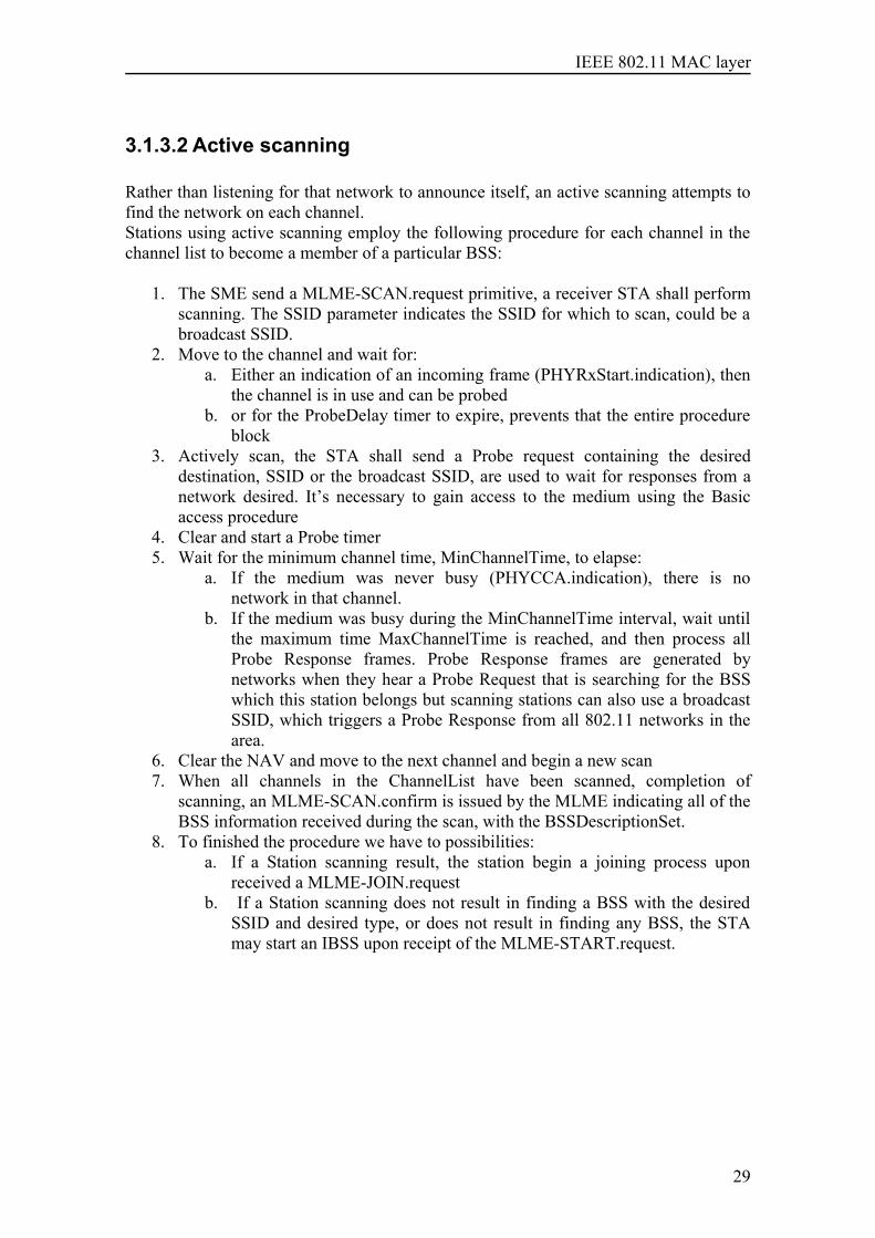
3.1.3.2 Active scanning
Rather than listening for that network to announce itself, an active scanning attempts tofind the network on each channel.Stations using active scanning employ the following procedure for each channel in thechannel list to become a member of a particular BSS:
1. The SME send a MLME-SCAN.request primitive, a receiver STA shall performscanning. The SSID parameter indicates the SSID for which to scan, could be abroadcast SSID.
2. Move to the channel and wait for:a. Either an indication of an incoming frame (PHYRxStart.indication), then
the channel is in use and can be probedb. or for the ProbeDelay timer to expire, prevents that the entire procedure
block3. Actively scan, the STA shall send a Probe request containing the desired
destination, SSID or the broadcast SSID, are used to wait for responses from anetwork desired. It’s necessary to gain access to the medium using the Basicaccess procedure
4. Clear and start a Probe timer5. Wait for the minimum channel time, MinChannelTime, to elapse:
a. If the medium was never busy (PHYCCA.indication), there is nonetwork in that channel.
b. If the medium was busy during the MinChannelTime interval, wait untilthe maximum time MaxChannelTime is reached, and then process allProbe Response frames. Probe Response frames are generated bynetworks when they hear a Probe Request that is searching for the BSSwhich this station belongs but scanning stations can also use a broadcastSSID, which triggers a Probe Response from all 802.11 networks in thearea.
6. Clear the NAV and move to the next channel and begin a new scan7. When all channels in the ChannelList have been scanned, completion of
scanning, an MLME-SCAN.confirm is issued by the MLME indicating all of theBSS information received during the scan, with the BSSDescriptionSet.
8. To finished the procedure we have to possibilities:a. If a Station scanning result, the station begin a joining process upon
received a MLME-JOIN.requestb. If a Station scanning does not result in finding a BSS with the desired
SSID and desired type, or does not result in finding any BSS, the STAmay start an IBSS upon receipt of the MLME-START.request.
29
IEEE 802.11 MAC layer
Continuation, it’s showed show you an example, with two IBSS working, and onestation trying to joining to the “Red” network. The right part of the scheme representsthe management side of the process that take place in the management architecture.
MLME-SCAN.request
SSID=”Red”
StationsStation A
MLME-SCAN.confirm BSSDescription of “Red”
Sta B Probe responseSSID=”Red”
SME
beaconSSID=”Red”MLME-Join.request
SSID=”Red”
MLME-Join.confirm BSSDescription of “Red”
MLME MLME SAP
Probe request Sta A
SSID=”Red”
Waiting for: -any incoming frame -or ProbeDelay expire
beaconSSID=”Red”
Sta B DataSSID=”Red”
Fig 31 Active scanning
30
IEEE 802.11 MAC layer
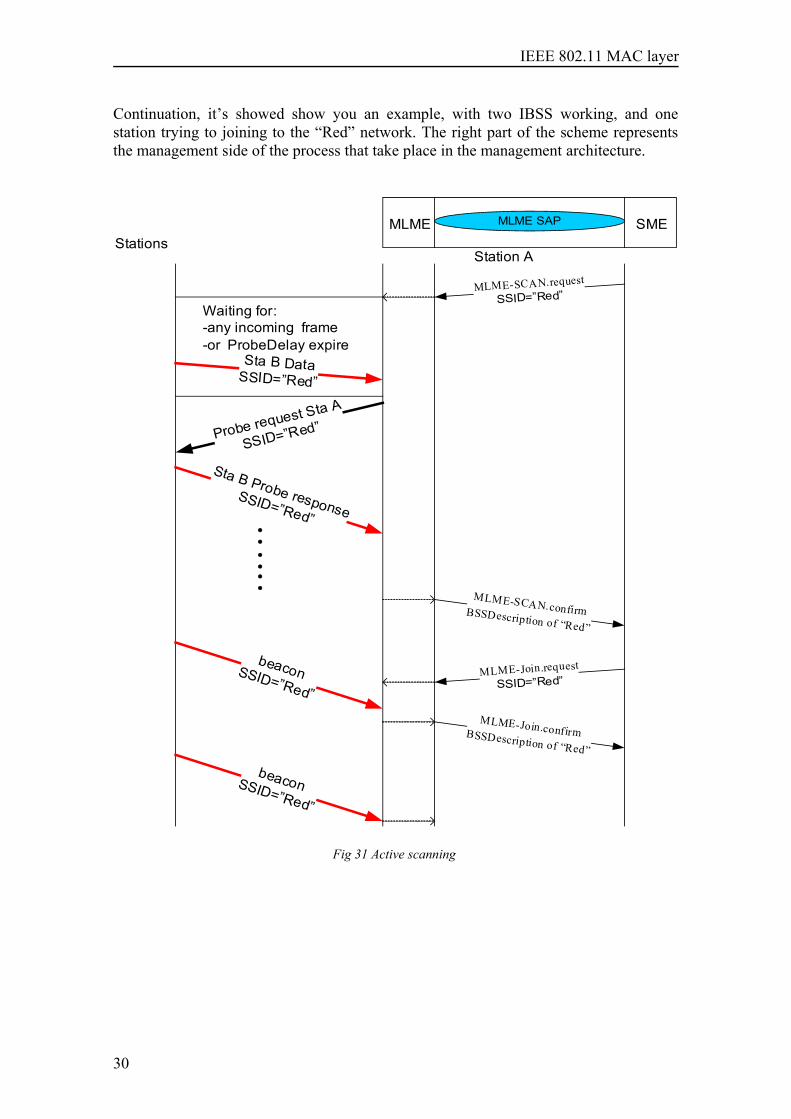
3.1.3.3 More about Probe request
One station is responsible for responding to Probe Requests in each BSS. The stationthat transmitted the last Beacon frame remain in the awake state and shall respond toprobe requests until a Beacon frame with the current BSSID is received. IBSSs passaround the responsibility of sending Beacon frames, so the station that transmits ProbeResponse frames varies. It’s possible multiple Probe Responses to be transmitted as a result of a single ProbeRequest. The purpose of the scanning procedure is to find every basic service area thatthe scanning station can join, so a broadcast Probe Request results in a response fromany overlapping independent BSSs may respond.Probe Responses are unicast management frames and are therefore subject to thepositive acknowledgment requirement of the MAC, with normal frame transmissionrules. There may be more than one STA in an IBSS that responds to any given proberequest, particularly in cases where more than one STA transmitted a Beacon framefollowing the most recent TBTT, either due to not receiving successfully a previousbeacon or due to collisions between beacon transmissions. Example: The figure showsthe relationship between the transmission of Probe frames and the various timingintervals that can be configured as part of a scan.
Scanning station STA A
STA B
STA C
Probe request
DIFS
Probe response
SIFS
ACK
DIFS
Probe response
SIFS
ACK
Min_Channel_Time Max_Channel_Time
Contention window
Fig 32 Probe request sequence
The scanning station transmits the Probe Request after gaining access to the medium.Both Stations respond with a Probe Response that reports their network's parameters.The first response is send before the minimum response time elapses, and the Station Amust wait until the finish of maximum response time, if we are expecting a lot of probesresponse we may configure the MaxChannelTime longer.
31
IEEE 802.11 MAC layer
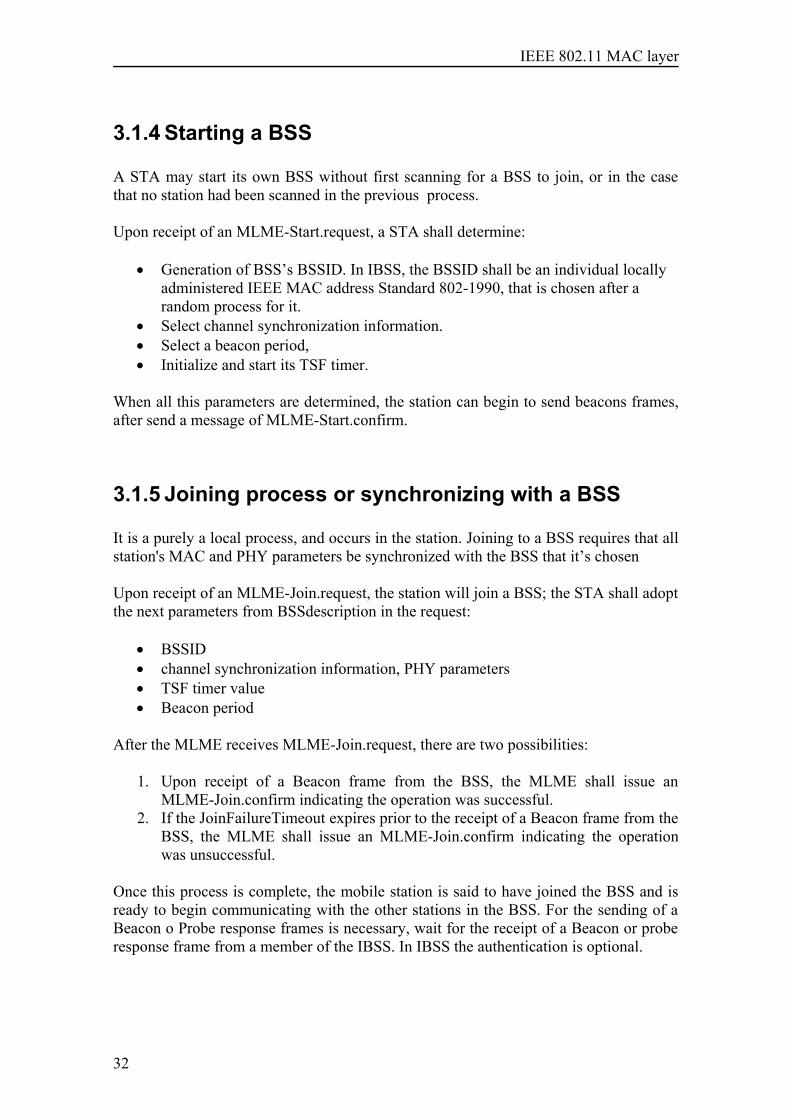
3.1.4 Starting a BSS
A STA may start its own BSS without first scanning for a BSS to join, or in the casethat no station had been scanned in the previous process.
Upon receipt of an MLME-Start.request, a STA shall determine:
• Generation of BSS’s BSSID. In IBSS, the BSSID shall be an individual locallyadministered IEEE MAC address Standard 802-1990, that is chosen after arandom process for it.
• Select channel synchronization information. • Select a beacon period, • Initialize and start its TSF timer.
When all this parameters are determined, the station can begin to send beacons frames,after send a message of MLME-Start.confirm.
3.1.5 Joining process or synchronizing with a BSS
It is a purely a local process, and occurs in the station. Joining to a BSS requires that allstation's MAC and PHY parameters be synchronized with the BSS that it’s chosen
Upon receipt of an MLME-Join.request, the station will join a BSS; the STA shall adoptthe next parameters from BSSdescription in the request:
• BSSID• channel synchronization information, PHY parameters• TSF timer value • Beacon period
After the MLME receives MLME-Join.request, there are two possibilities:
1. Upon receipt of a Beacon frame from the BSS, the MLME shall issue anMLME-Join.confirm indicating the operation was successful.
2. If the JoinFailureTimeout expires prior to the receipt of a Beacon frame from theBSS, the MLME shall issue an MLME-Join.confirm indicating the operationwas unsuccessful.
Once this process is complete, the mobile station is said to have joined the BSS and isready to begin communicating with the other stations in the BSS. For the sending of aBeacon o Probe response frames is necessary, wait for the receipt of a Beacon or proberesponse frame from a member of the IBSS. In IBSS the authentication is optional.
32
IEEE 802.11 MAC layer
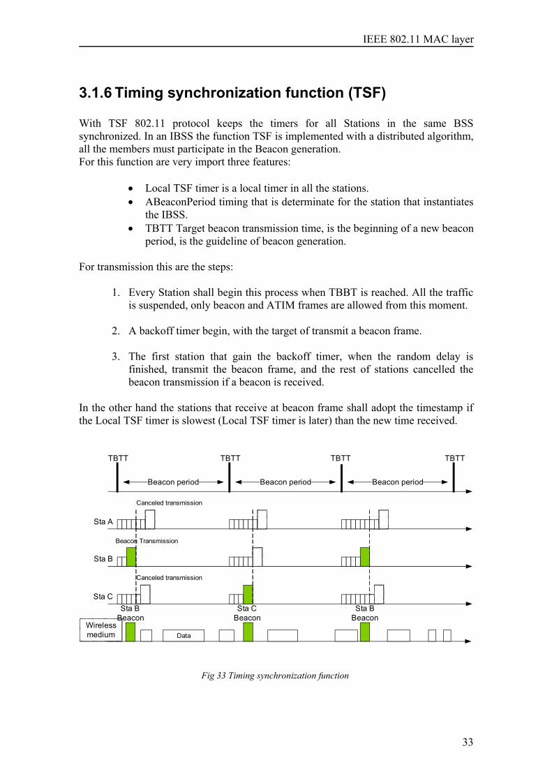
3.1.6 Timing synchronization function (TSF)
With TSF 802.11 protocol keeps the timers for all Stations in the same BSSsynchronized. In an IBSS the function TSF is implemented with a distributed algorithm,all the members must participate in the Beacon generation.For this function are very import three features:
• Local TSF timer is a local timer in all the stations.• ABeaconPeriod timing that is determinate for the station that instantiates
the IBSS.• TBTT Target beacon transmission time, is the beginning of a new beacon
period, is the guideline of beacon generation.
For transmission this are the steps:
1. Every Station shall begin this process when TBBT is reached. All the trafficis suspended, only beacon and ATIM frames are allowed from this moment.
2. A backoff timer begin, with the target of transmit a beacon frame.
3. The first station that gain the backoff timer, when the random delay isfinished, transmit the beacon frame, and the rest of stations cancelled thebeacon transmission if a beacon is received.
In the other hand the stations that receive at beacon frame shall adopt the timestamp ifthe Local TSF timer is slowest (Local TSF timer is later) than the new time received.
Beacon period
TBTT TBTT TBTT TBTT
Beacon period Beacon period
Beacon Transmission
Canceled transmission
Canceled transmission
Sta A
Sta CSta B
Beacon
Sta B
Sta B Beacon
DataWireless medium
Sta C Beacon
Fig 33 Timing synchronization function
33

IEEE 802.11 MAC layer
34
IEEE 802.11 MAC layer
4 Access control and Coordinationfunctions
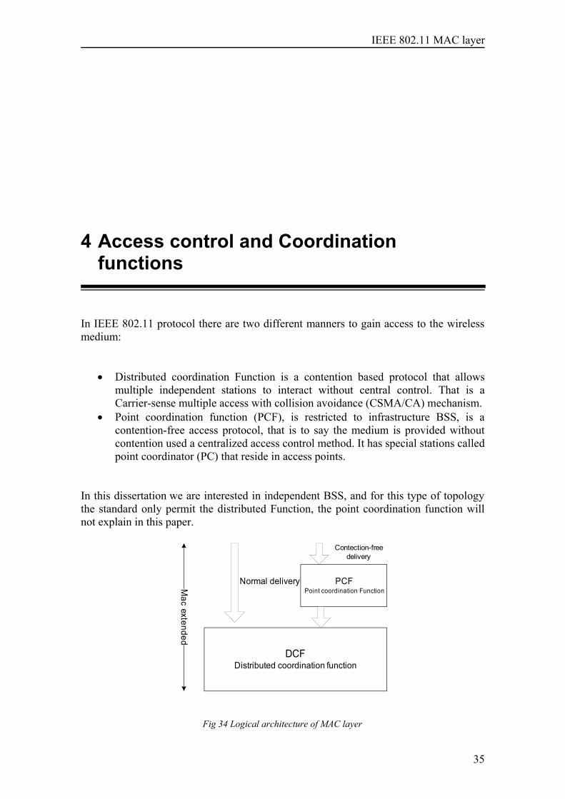
In IEEE 802.11 protocol there are two different manners to gain access to the wirelessmedium:
• Distributed coordination Function is a contention based protocol that allowsmultiple independent stations to interact without central control. That is aCarrier-sense multiple access with collision avoidance (CSMA/CA) mechanism.
• Point coordination function (PCF), is restricted to infrastructure BSS, is acontention-free access protocol, that is to say the medium is provided withoutcontention used a centralized access control method. It has special stations calledpoint coordinator (PC) that reside in access points.
In this dissertation we are interested in independent BSS, and for this type of topologythe standard only permit the distributed Function, the point coordination function willnot explain in this paper.
DCFDistributed coordination function
PCFPoint coordination Function
Normal delivery
Contection-free delivery
Mac extended
Fig 34 Logical architecture of MAC layer
35
IEEE 802.11 MAC layer
4.1 Distributed coordination Function andcontention based access
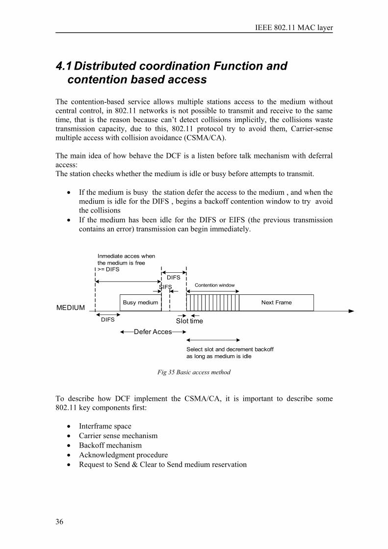
The contention-based service allows multiple stations access to the medium withoutcentral control, in 802.11 networks is not possible to transmit and receive to the sametime, that is the reason because can’t detect collisions implicitly, the collisions wastetransmission capacity, due to this, 802.11 protocol try to avoid them, Carrier-sensemultiple access with collision avoidance (CSMA/CA).
The main idea of how behave the DCF is a listen before talk mechanism with deferralaccess:The station checks whether the medium is idle or busy before attempts to transmit.
• If the medium is busy the station defer the access to the medium , and when themedium is idle for the DIFS , begins a backoff contention window to try avoidthe collisions
• If the medium has been idle for the DIFS or EIFS (the previous transmissioncontains an error) transmission can begin immediately.
MEDIUMBusy medium
DIFS
SIFS
DIFSContention window
Next Frame
Defer AccesSlot time
Select slot and decrement backoff as long as medium is idle
Inmediate acces when the medium is free >= DIFS
Fig 35 Basic access method
To describe how DCF implement the CSMA/CA, it is important to describe some802.11 key components first:
• Interframe space• Carrier sense mechanism• Backoff mechanism• Acknowledgment procedure• Request to Send & Clear to Send medium reservation
36
IEEE 802.11 MAC layer
4.1.1 Interframe space
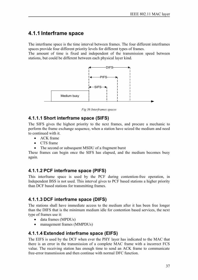
The interframe space is the time interval between frames. The four different interframesspaces provide four different priority levels for different types of frames.The amount of time is fixed and independent of the transmission speed betweenstations, but could be different between each physical layer kind.
Medium busy
SIFS
PIFS
DIFS
Fig 36 Interframes spaces
4.1.1.1 Short interframe space (SIFS)The SIFS gives the highest priority to the next frames, and procure a mechanic toperform the frame exchange sequence, when a station have seized the medium and needto continued with it.
• ACK frame• CTS frame• The second or subsequent MSDU of a fragment burst
These frames can begin once the SIFS has elapsed, and the medium becomes busyagain.
4.1.1.2 PCF interframe space (PIFS)This interframe space is used by the PCF during contention-free operation, inIndependent BSS is not used. This interval gives to PCF based stations a higher prioritythan DCF based stations for transmitting frames.
4.1.1.3 DCF interframe space (DIFS)The stations shall have immediate access to the medium after it has been free longerthan the DIFS that is the minimum medium idle for contention based services, the nexttype of frames use it:
• data frames (MPDUs) • management frames (MMPDUs)
4.1.1.4 Extended interframe space (EIFS)The EIFS is used by the DCF when ever the PHY layer has indicated to the MAC thatthere is an error in the transmission of a complete MAC frame with a incorrect FCSvalue. The receiving station has enough time to send an ACK frame to communicatefree-error transmission and then continue with normal DFC function.
37
IEEE 802.11 MAC layer
4.1.2 Carrier-sense mechanism
There are two different mechanisms to determinate the state of the medium, this isessential for CSMA/CA, because provide sufficient information for the Mac to decidethe status of the channel.
• Physical carrier-sense mechanism, it’s provided by the Physical layer, checkthe channel, and see whether a carrier is present, by analyzing all detectedpackets or detects activity by the signal strength from other stations. Thephysical layer sends to the Mac coordination the result of the physical channelassessment.
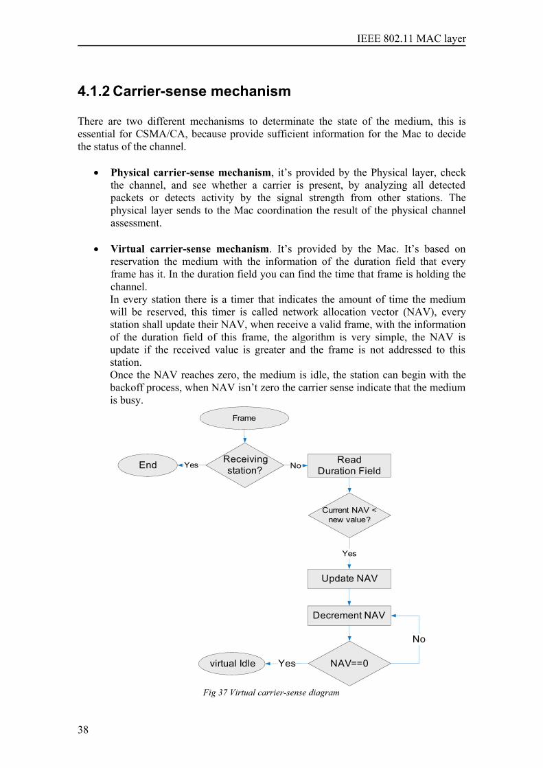
• Virtual carrier-sense mechanism. It’s provided by the Mac. It’s based onreservation the medium with the information of the duration field that everyframe has it. In the duration field you can find the time that frame is holding thechannel. In every station there is a timer that indicates the amount of time the mediumwill be reserved, this timer is called network allocation vector (NAV), everystation shall update their NAV, when receive a valid frame, with the informationof the duration field of this frame, the algorithm is very simple, the NAV isupdate if the received value is greater and the frame is not addressed to thisstation. Once the NAV reaches zero, the medium is idle, the station can begin with thebackoff process, when NAV isn’t zero the carrier sense indicate that the mediumis busy.
Read Duration Field
Frame
Receiving station?
Current NAV < new value?
Update NAV
Decrement NAV
NAV==0
End
virtual Idle
No
Yes
Yes
Yes
No
Fig 37 Virtual carrier-sense diagram
38
IEEE 802.11 MAC layer
4.1.3 Backoff procedure
Random backoff period is an additional deferred time before transmit, that minimizescollisions during contention process between multiple stations that try to gain themedium. This process minimizes collisions during contention between multiple Stationsthat have been deferring to the same event. It’s a mechanism to manage congestion, duethe number of nodes could attempt to transmit at the same moment are changing withtime, to deal this situation the DCF dynamically adjust the contention window.
4.1.3.1 Contention window CW parameter
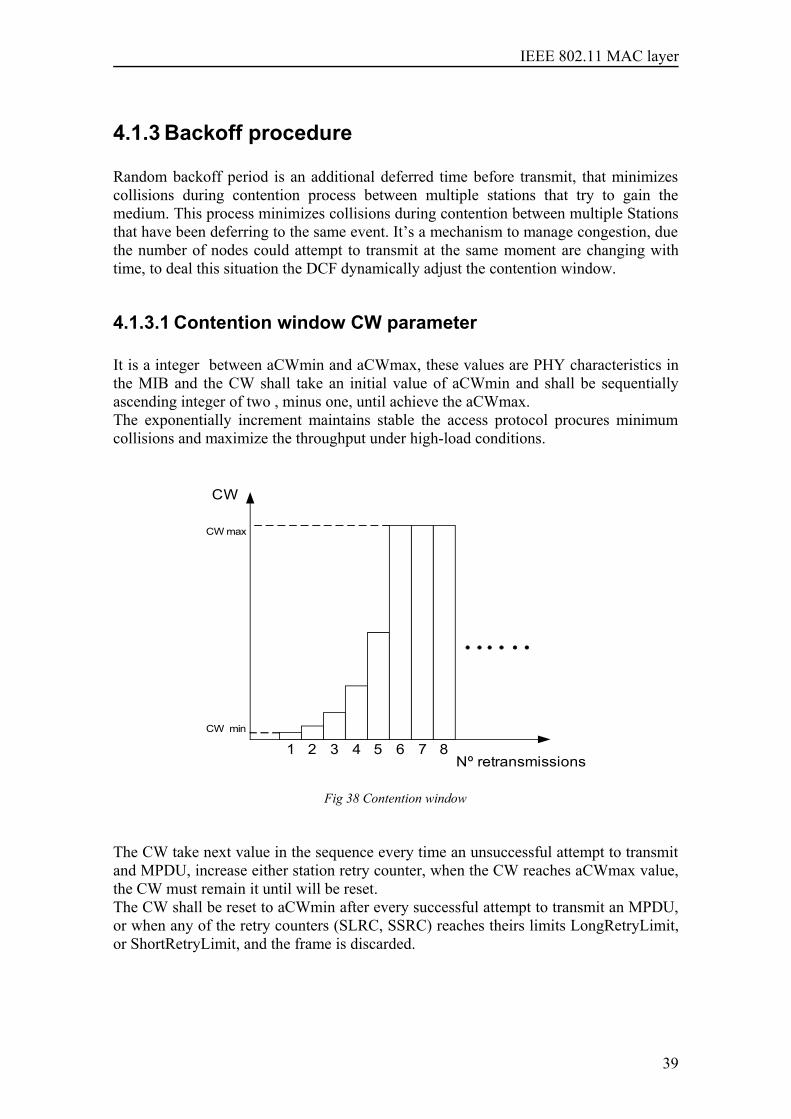
It is a integer between aCWmin and aCWmax, these values are PHY characteristics inthe MIB and the CW shall take an initial value of aCWmin and shall be sequentiallyascending integer of two , minus one, until achieve the aCWmax.The exponentially increment maintains stable the access protocol procures minimumcollisions and maximize the throughput under high-load conditions.
CW
CW max
CW min
Nº retransmissions1 5 62 3 4 7 8
Fig 38 Contention window
The CW take next value in the sequence every time an unsuccessful attempt to transmitand MPDU, increase either station retry counter, when the CW reaches aCWmax value,the CW must remain it until will be reset.The CW shall be reset to aCWmin after every successful attempt to transmit an MPDU,or when any of the retry counters (SLRC, SSRC) reaches theirs limits LongRetryLimit,or ShortRetryLimit, and the frame is discarded.
39
IEEE 802.11 MAC layer
4.1.3.1.1.Station short retry count (SSRC)
This counter is local to every station and is incrementing when a sort frametransmission fail and there is a retransmission. The station begins with this counter if theframe that is transmitting is shorter than the RTS threshold.
The short retry counter is reset to zero whenever:• A CTS frame is received in response to an RTS frame.• A Mac ACK frame is received in response to an MPDU transmission.• A broadcast or multicast is transmit
The maximum number of short frames retransmission is set by ShortRetryLimitthe default value is seven.
4.1.3.1.2.Station long retry count (SLRC)
This counter is local to every station and is incrementing when a long frametransmission fails and there is a retransmission. The station begins with this counter ifthe frame that is transmitting is longer than the RTS threshold.
The long retry counter is reset to zero whenever:• Mac ACK frame is received in response to transmission of an MPDU of length
greater than RTS Threshold,• A broadcast or multicast is transmit
The maximum number of long frames retransmission is set by LongRetryLimit, thedefault value is four.
4.1.3.2 Backoff interval time
It is generated by a random process in the station using the following formula:
Backoff Time = Random ( ) x aSlotTime
• Random : is Pseudorandom integer drawn from a uniform distribution over theinterval [0,CW]
• aSlotTime is a constant parameter of each physical layer
In every station there is a local Backoff timer that is update to the backoff time ifcontains zero value, in other way maintain the value of the count in progress.
40
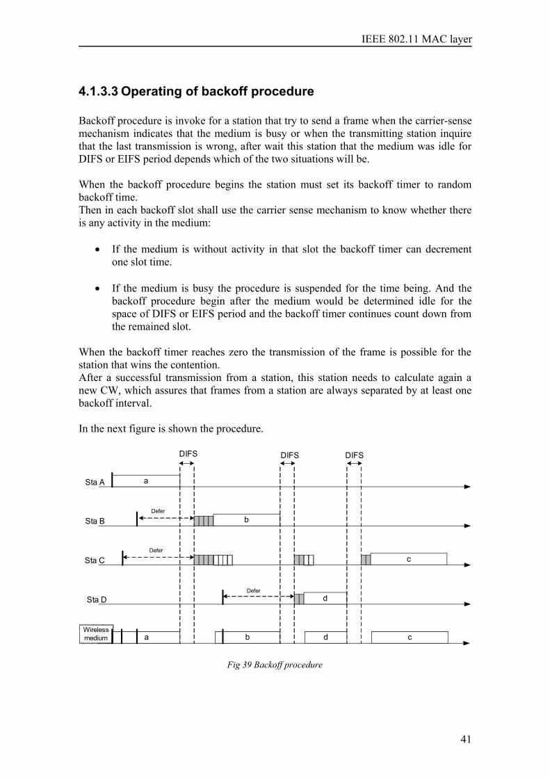
IEEE 802.11 MAC layer
4.1.3.3 Operating of backoff procedure
Backoff procedure is invoke for a station that try to send a frame when the carrier-sensemechanism indicates that the medium is busy or when the transmitting station inquirethat the last transmission is wrong, after wait this station that the medium was idle forDIFS or EIFS period depends which of the two situations will be.
When the backoff procedure begins the station must set its backoff timer to randombackoff time.Then in each backoff slot shall use the carrier sense mechanism to know whether thereis any activity in the medium:
• If the medium is without activity in that slot the backoff timer can decrementone slot time.
• If the medium is busy the procedure is suspended for the time being. And thebackoff procedure begin after the medium would be determined idle for thespace of DIFS or EIFS period and the backoff timer continues count down fromthe remained slot.
When the backoff timer reaches zero the transmission of the frame is possible for thestation that wins the contention.After a successful transmission from a station, this station needs to calculate again anew CW, which assures that frames from a station are always separated by at least onebackoff interval. In the next figure is shown the procedure.
Sta A
Sta C
Sta B
Wireless medium
a
Sta D
a
b
b
d
d
c
c
DIFS DIFS DIFS
Defer
Defer
Defer
Fig 39 Backoff procedure
41
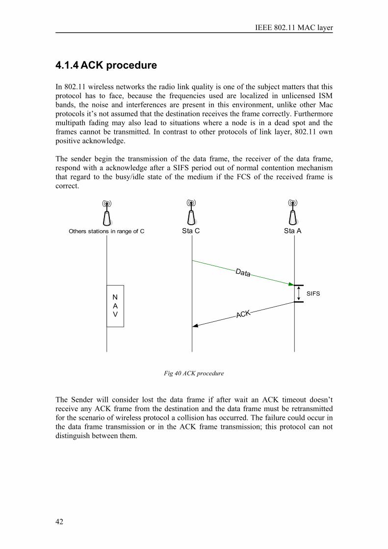
IEEE 802.11 MAC layer
4.1.4 ACK procedure
In 802.11 wireless networks the radio link quality is one of the subject matters that thisprotocol has to face, because the frequencies used are localized in unlicensed ISMbands, the noise and interferences are present in this environment, unlike other Macprotocols it’s not assumed that the destination receives the frame correctly. Furthermoremultipath fading may also lead to situations where a node is in a dead spot and theframes cannot be transmitted. In contrast to other protocols of link layer, 802.11 ownpositive acknowledge.
The sender begin the transmission of the data frame, the receiver of the data frame,respond with a acknowledge after a SIFS period out of normal contention mechanismthat regard to the busy/idle state of the medium if the FCS of the received frame iscorrect.
Data
Sta ASta C
ACK
SIFS
Others stations in range of C
NAV
Fig 40 ACK procedure
The Sender will consider lost the data frame if after wait an ACK timeout doesn’treceive any ACK frame from the destination and the data frame must be retransmittedfor the scenario of wireless protocol a collision has occurred. The failure could occur inthe data frame transmission or in the ACK frame transmission; this protocol can notdistinguish between them.
42
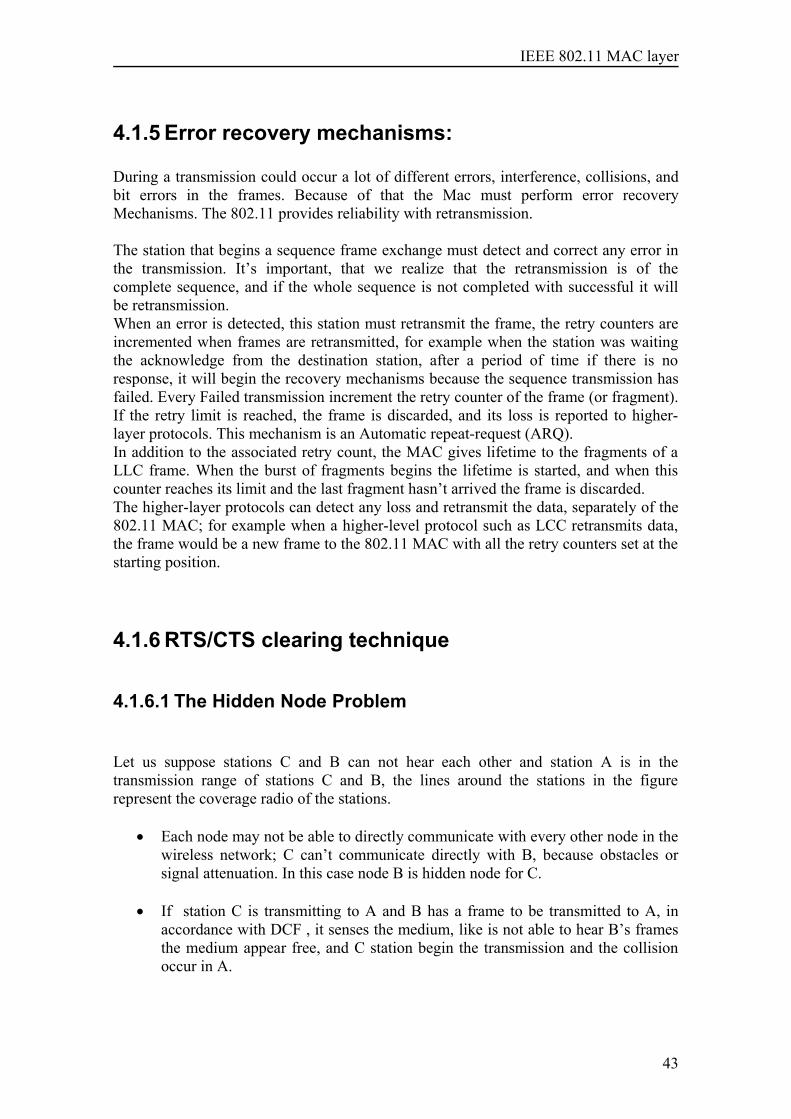
IEEE 802.11 MAC layer
4.1.5 Error recovery mechanisms:
During a transmission could occur a lot of different errors, interference, collisions, andbit errors in the frames. Because of that the Mac must perform error recoveryMechanisms. The 802.11 provides reliability with retransmission.
The station that begins a sequence frame exchange must detect and correct any error inthe transmission. It’s important, that we realize that the retransmission is of thecomplete sequence, and if the whole sequence is not completed with successful it willbe retransmission. When an error is detected, this station must retransmit the frame, the retry counters areincremented when frames are retransmitted, for example when the station was waitingthe acknowledge from the destination station, after a period of time if there is noresponse, it will begin the recovery mechanisms because the sequence transmission hasfailed. Every Failed transmission increment the retry counter of the frame (or fragment).If the retry limit is reached, the frame is discarded, and its loss is reported to higher-layer protocols. This mechanism is an Automatic repeat-request (ARQ). In addition to the associated retry count, the MAC gives lifetime to the fragments of aLLC frame. When the burst of fragments begins the lifetime is started, and when thiscounter reaches its limit and the last fragment hasn’t arrived the frame is discarded. The higher-layer protocols can detect any loss and retransmit the data, separately of the802.11 MAC; for example when a higher-level protocol such as LCC retransmits data,the frame would be a new frame to the 802.11 MAC with all the retry counters set at thestarting position.
4.1.6 RTS/CTS clearing technique
4.1.6.1 The Hidden Node Problem
Let us suppose stations C and B can not hear each other and station A is in thetransmission range of stations C and B, the lines around the stations in the figurerepresent the coverage radio of the stations.
• Each node may not be able to directly communicate with every other node in thewireless network; C can’t communicate directly with B, because obstacles orsignal attenuation. In this case node B is hidden node for C.
• If station C is transmitting to A and B has a frame to be transmitted to A, inaccordance with DCF , it senses the medium, like is not able to hear B’s framesthe medium appear free, and C station begin the transmission and the collisionoccur in A.
43
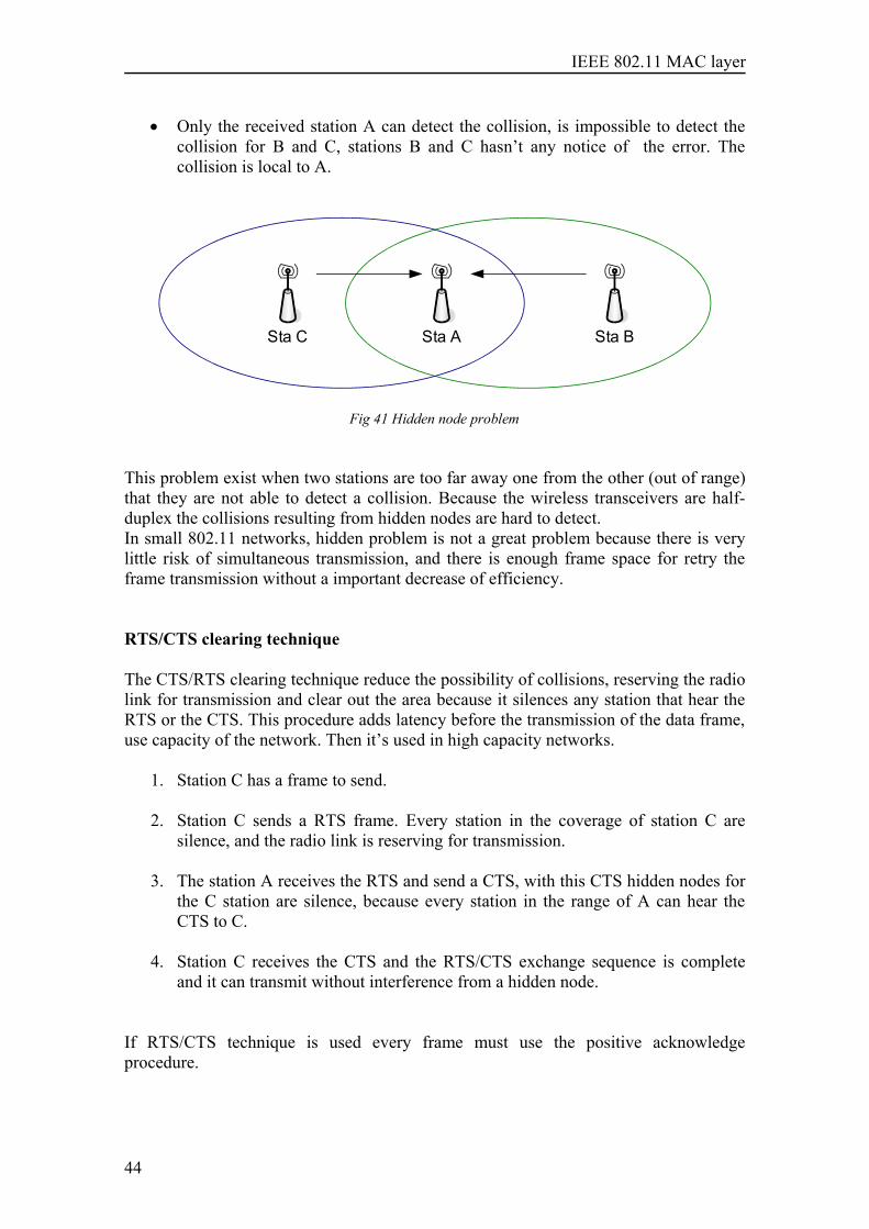
IEEE 802.11 MAC layer
• Only the received station A can detect the collision, is impossible to detect thecollision for B and C, stations B and C hasn’t any notice of the error. Thecollision is local to A.
Sta ASta C Sta B
Fig 41 Hidden node problem
This problem exist when two stations are too far away one from the other (out of range)that they are not able to detect a collision. Because the wireless transceivers are half-duplex the collisions resulting from hidden nodes are hard to detect.In small 802.11 networks, hidden problem is not a great problem because there is verylittle risk of simultaneous transmission, and there is enough frame space for retry theframe transmission without a important decrease of efficiency.
RTS/CTS clearing technique
The CTS/RTS clearing technique reduce the possibility of collisions, reserving the radiolink for transmission and clear out the area because it silences any station that hear theRTS or the CTS. This procedure adds latency before the transmission of the data frame,use capacity of the network. Then it’s used in high capacity networks.
1. Station C has a frame to send.
2. Station C sends a RTS frame. Every station in the coverage of station C aresilence, and the radio link is reserving for transmission.
3. The station A receives the RTS and send a CTS, with this CTS hidden nodes forthe C station are silence, because every station in the range of A can hear theCTS to C.
4. Station C receives the CTS and the RTS/CTS exchange sequence is completeand it can transmit without interference from a hidden node.
If RTS/CTS technique is used every frame must use the positive acknowledgeprocedure.
44
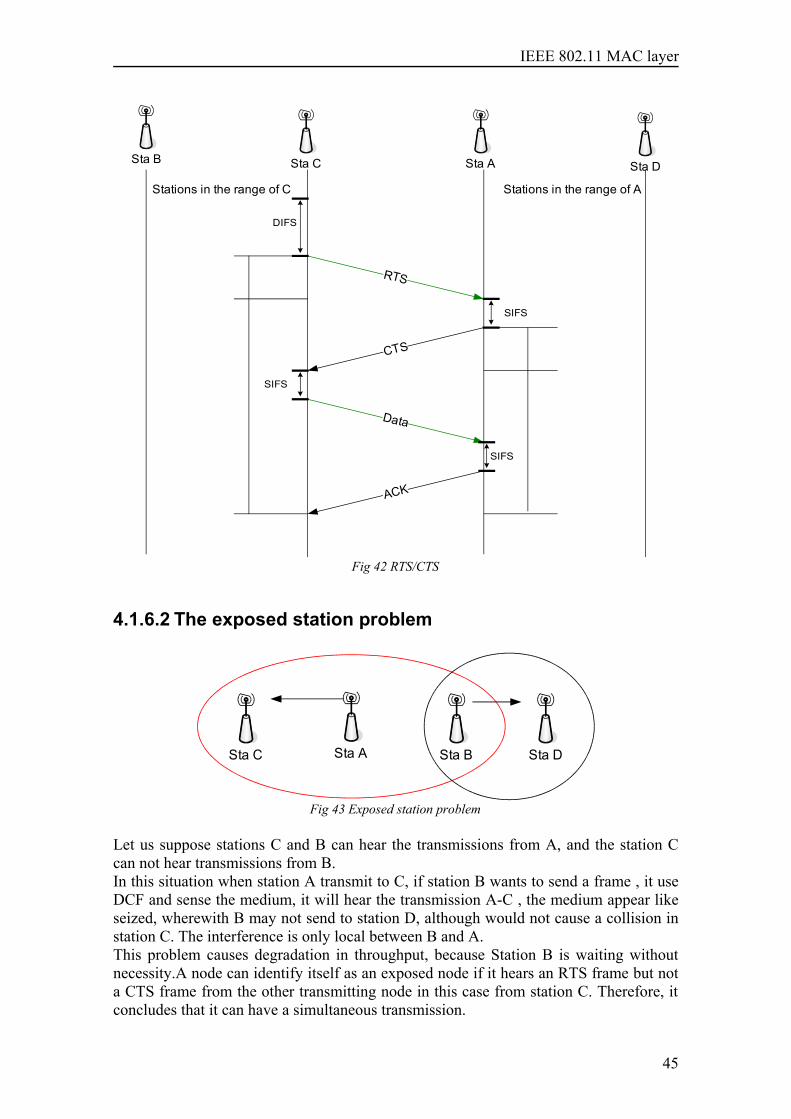
IEEE 802.11 MAC layer
RTS
Sta ASta C Sta D
CTS
Data
ACK
SIFS
SIFS
SIFS
Sta B
Stations in the range of AStations in the range of C
DIFS
Fig 42 RTS/CTS
4.1.6.2 The exposed station problem
Sta ASta C Sta B Sta D
Fig 43 Exposed station problem
Let us suppose stations C and B can hear the transmissions from A, and the station Ccan not hear transmissions from B.In this situation when station A transmit to C, if station B wants to send a frame , it useDCF and sense the medium, it will hear the transmission A-C , the medium appear likeseized, wherewith B may not send to station D, although would not cause a collision instation C. The interference is only local between B and A.This problem causes degradation in throughput, because Station B is waiting withoutnecessity.A node can identify itself as an exposed node if it hears an RTS frame but nota CTS frame from the other transmitting node in this case from station C. Therefore, itconcludes that it can have a simultaneous transmission.
45
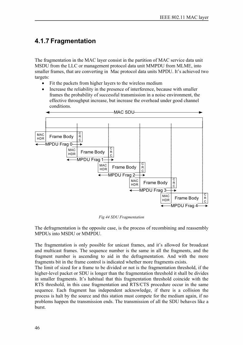
IEEE 802.11 MAC layer
4.1.7 Fragmentation
The fragmentation in the MAC layer consist in the partition of MAC service data unitMSDU from the LLC or management protocol data unit MMPDU from MLME, intosmaller frames, that are converting in Mac protocol data units MPDU. It’s achieved twotargets:
• Fit the packets from higher layers to the wireless medium• Increase the reliability in the presence of interference, because with smaller
frames the probability of successful transmission in a noise environment, theeffective throughput increase, but increase the overhead under good channelconditions.
MACHDR Frame Body
CRC
MACHDR Frame Body
CRC
MACHDR Frame Body
CRC
MACHDR Frame Body
CRC
MACHDR Frame Body
CRC
MAC SDU
MPDU Frag 0
MPDU Frag 1
MPDU Frag 2
MPDU Frag 3
MPDU Frag 4
Fig 44 SDU Fragmentation
The defragmentation is the opposite case, is the process of recombining and reassemblyMPDUs into MSDU or MMPDU.
The fragmentation is only possible for unicast frames, and it’s allowed for broadcastand multicast frames. The sequence number is the same in all the fragments, and thefragment number is ascending to aid in the defragmentation. And with the morefragments bit in the frame control is indicated whether more fragments exists.The limit of sized for a frame to be divided or not is the fragmentation threshold, if thehigher-level packet or SDU is longer than the fragmentation threshold it shall be dividesin smaller fragments. It’s habitual that this fragmentation threshold coincide with theRTS threshold, in this case fragmentation and RTS/CTS procedure occur in the samesequence. Each fragment has independent acknowledge, if there is a collision theprocess is halt by the source and this station must compete for the medium again, if noproblems happen the transmission ends. The transmission of all the SDU behaves like aburst.
46
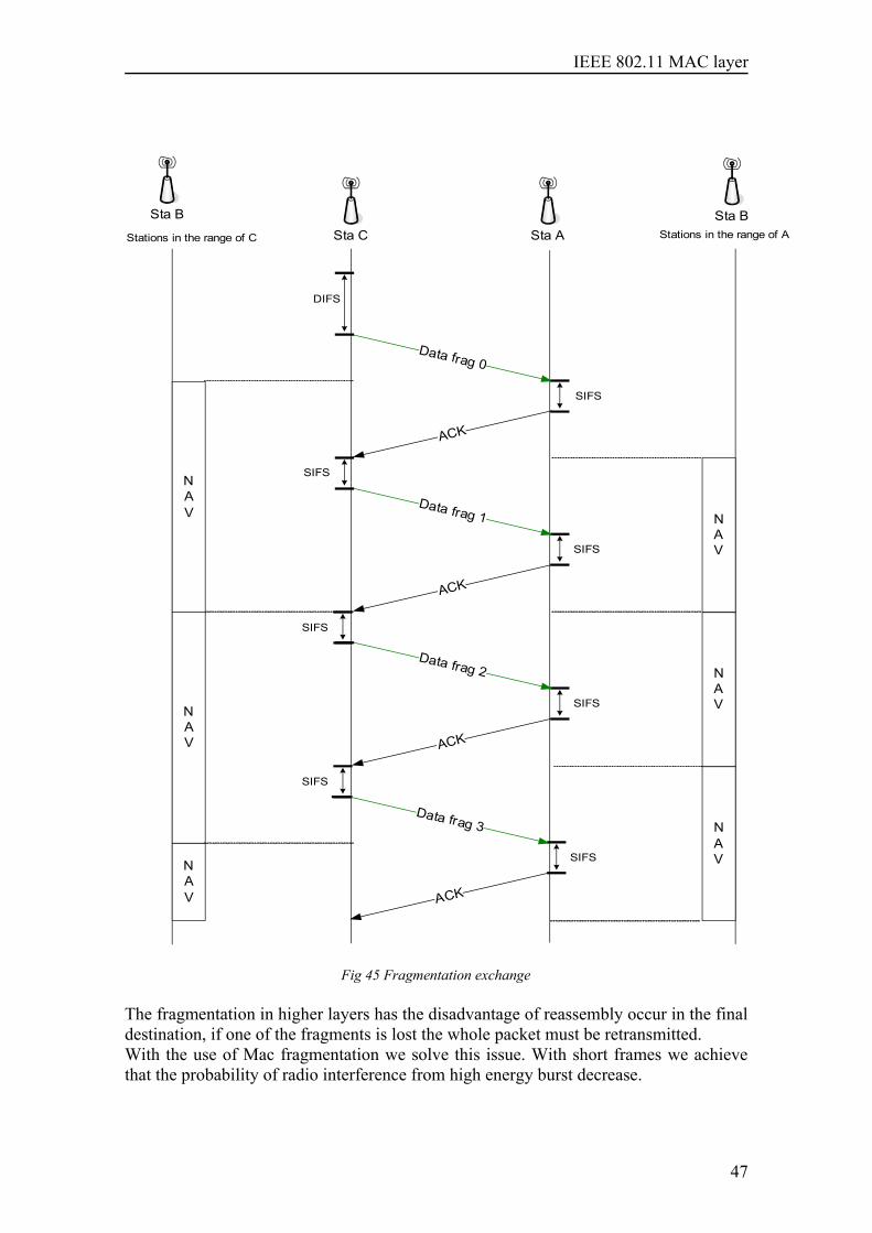
IEEE 802.11 MAC layer
Sta ASta CSta B
Data frag 0
ACK
SIFS
SIFS
SIFS
Sta BStations in the range of AStations in the range of C
DIFS
NAV N
AV
Data frag 1
ACK
SIFS
SIFS
Data frag 2
ACK
SIFS
SIFS
Data frag 3
ACK
NAV
NAV
NAV
NAV
Fig 45 Fragmentation exchange
The fragmentation in higher layers has the disadvantage of reassembly occur in the finaldestination, if one of the fragments is lost the whole packet must be retransmitted.With the use of Mac fragmentation we solve this issue. With short frames we achievethat the probability of radio interference from high energy burst decrease.
47
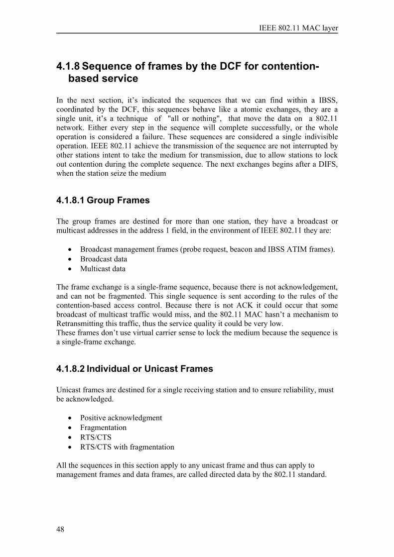
IEEE 802.11 MAC layer
4.1.8 Sequence of frames by the DCF for contention-based service
In the next section, it’s indicated the sequences that we can find within a IBSS,coordinated by the DCF, this sequences behave like a atomic exchanges, they are asingle unit, it’s a technique of "all or nothing", that move the data on a 802.11network. Either every step in the sequence will complete successfully, or the wholeoperation is considered a failure. These sequences are considered a single indivisibleoperation. IEEE 802.11 achieve the transmission of the sequence are not interrupted byother stations intent to take the medium for transmission, due to allow stations to lockout contention during the complete sequence. The next exchanges begins after a DIFS,when the station seize the medium
4.1.8.1 Group Frames
The group frames are destined for more than one station, they have a broadcast ormulticast addresses in the address 1 field, in the environment of IEEE 802.11 they are:
• Broadcast management frames (probe request, beacon and IBSS ATIM frames).• Broadcast data• Multicast data
The frame exchange is a single-frame sequence, because there is not acknowledgement,and can not be fragmented. This single sequence is sent according to the rules of thecontention-based access control. Because there is not ACK it could occur that somebroadcast of multicast traffic would miss, and the 802.11 MAC hasn’t a mechanism toRetransmitting this traffic, thus the service quality it could be very low. These frames don’t use virtual carrier sense to lock the medium because the sequence isa single-frame exchange.
4.1.8.2 Individual or Unicast Frames
Unicast frames are destined for a single receiving station and to ensure reliability, mustbe acknowledged.
• Positive acknowledgment• Fragmentation• RTS/CTS• RTS/CTS with fragmentation
All the sequences in this section apply to any unicast frame and thus can apply tomanagement frames and data frames, are called directed data by the 802.11 standard.
48
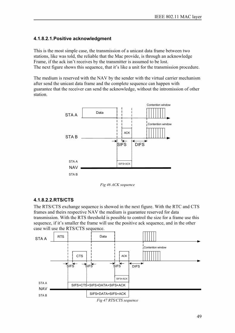
IEEE 802.11 MAC layer
4.1.8.2.1.Positive acknowledgment
This is the most simple case, the transmission of a unicast data frame between twostations, like was told, the reliable that the Mac provide, is through an acknowledgeFrame, if the ack isn’t receives by the transmitter is assumed to be lost.The next figure shows this sequence, that it’s like a unit for the transmission procedure.
The medium is reserved with the NAV by the sender with the virtual carrier mechanismafter send the unicast data frame and the complete sequence can happen withguarantee that the receiver can send the acknowledge, without the intromission of otherstation.
STA A
STA B
Data
SIFS+ACK
SIFS DIFS
ACK
Contention window
Contention window
NAV STA A
STA B
Fig 46 ACK sequence
4.1.8.2.2.RTS/CTSThe RTS/CTS exchange sequence is showed in the next figure. With the RTC and CTSframes and theirs respective NAV the medium is guarantee reserved for datatransmission. With the RTS threshold is possible to control the size for a frame use thissequence, if it’s smaller the frame will use the positive ack sequence, and in the othercase will use the RTS/CTS sequence.
STA A Data
SIFS+ACK
SIFS DIFS
ACK
Contention window
NAV STA A
STA B
RTS
SIFS
CTS
SIFS
SIFS+CTS+SIFS+DATA+SIFS+ACK
SIFS+DATA+SIFS+ACK
Fig 47 RTS/CTS sequence
49
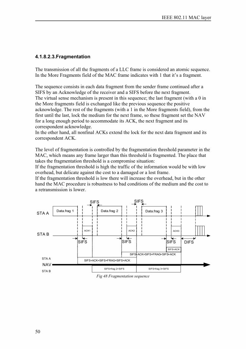
IEEE 802.11 MAC layer
4.1.8.2.3.Fragmentation
The transmission of all the fragments of a LLC frame is considered an atomic sequence.In the More Fragments field of the MAC frame indicates with 1 that it’s a fragment.
The sequence consists in each data fragment from the sender frame continued after aSIFS by an Acknowledge of the receiver and a SIFS before the next fragment.The virtual sense mechanism is present in this sequence; the last fragment (with a 0 inthe More fragments field is exchanged like the previous sequence the positiveacknowledge. The rest of the fragments (with a 1 in the More fragments field), from thefirst until the last, lock the medium for the next frame, so these fragment set the NAVfor a long enough period to accommodate its ACK, the next fragment and itscorrespondent acknowledge.In the other hand, all nonfinal ACKs extend the lock for the next data fragment and itscorrespondent ACK.
The level of fragmentation is controlled by the fragmentation threshold parameter in theMAC, which means any frame larger than this threshold is fragmented. The place thattakes the fragmentation threshold is a compromise situation:If the fragmentation threshold is high the traffic of the information would be with lowoverhead, but delicate against the cost to a damaged or a lost frame.If the fragmentation threshold is low there will increase the overhead, but in the otherhand the MAC procedure is robustness to bad conditions of the medium and the cost toa retransmission is lower.
STA A
STA B
NAV
Data.frag 1
SIFS
ACK1
Data.frag 2
SIFS
ACK2
SIFS+ACK+SIFS+FRAG+SIFS+ACK
Data.frag 3
SIFS
ACK3
DIFS
SIFS SIFS
SIFS+frag 2+SIFS SIFS+frag 3+SIFS
SIFS+ACK
SIFS+ACK+SIFS+FRAG+SIFS+ACK STA A
STA B
Fig 48 Fragmentation sequence
50
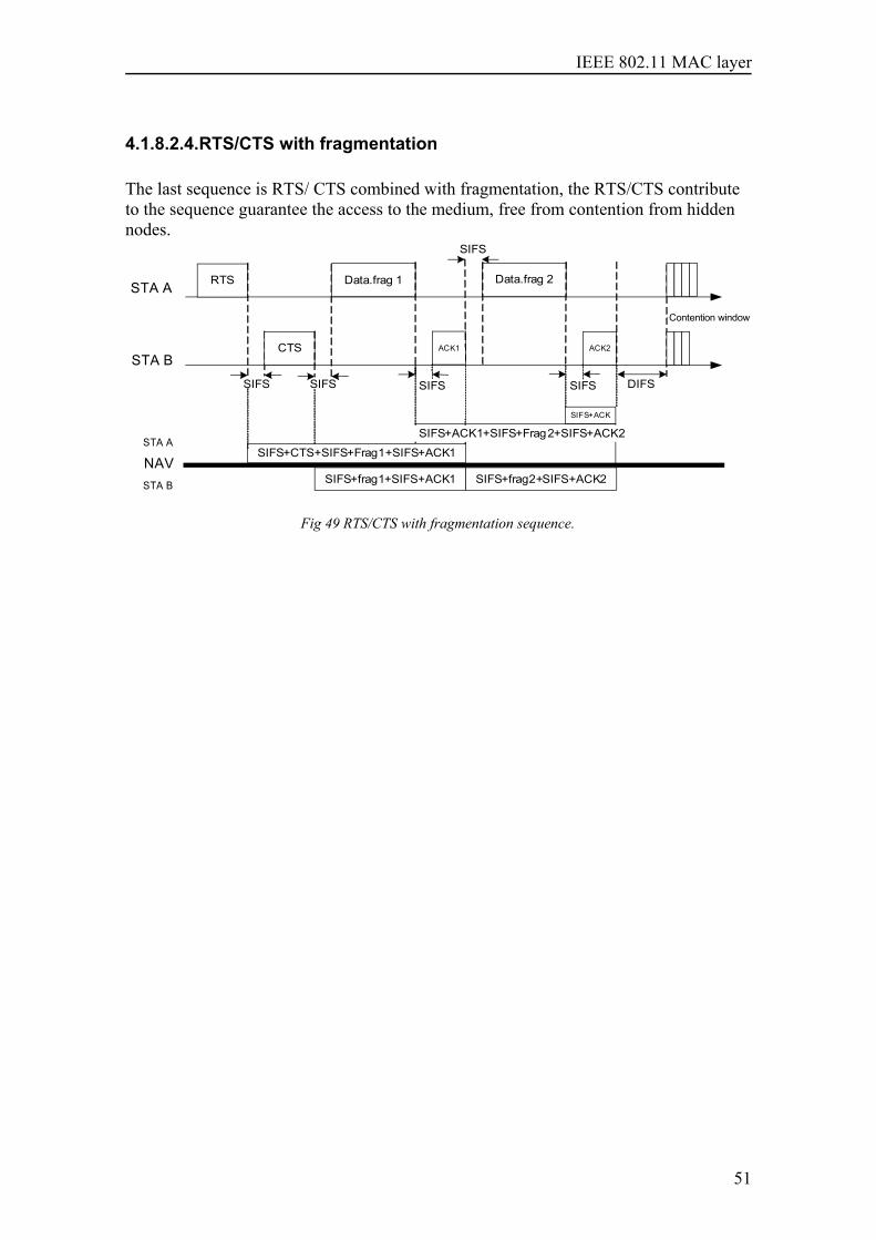
IEEE 802.11 MAC layer
4.1.8.2.4.RTS/CTS with fragmentation
The last sequence is RTS/ CTS combined with fragmentation, the RTS/CTS contributeto the sequence guarantee the access to the medium, free from contention from hiddennodes.
STA A
STA B
SIFS+ACK
NAV STA A
STA B
RTS
SIFS
CTS
SIFS
SIFS+CTS+SIFS+Frag1+SIFS+ACK1
SIFS+frag1+SIFS+ACK1
Data.frag 1
SIFS
ACK1
Data.frag 2
SIFS
ACK2
SIFS
SIFS+frag2+SIFS+ACK2
DIFS
Contention window
SIFS+ACK1+SIFS+Frag2+SIFS+ACK2
Fig 49 RTS/CTS with fragmentation sequence.
51

IEEE 802.11 MAC layer
52
IEEE 802.11 MAC layer
5 Comparison with standard IEEE 802.16
In this chapter two different comparisons are present. The first one is an introduction tothe technology of these features, and makes the reader notices the general features ofeach one. This aspect is important to obtain a global idea in order to provide enoughknowledge in case of treating a wireless networks planning. The second one is theproduce of the previous Mac layer research; work out in the anterior chapters in the caseof standard 802.11, and for standard 802.16 in the paper of Pedro Francisco Robles Ricowith are named like “Research of IEEE standard 802.16 MAC layer in DistributedMesh Networks and comparison with IEEE 802.11 ad hoc networks”.
53
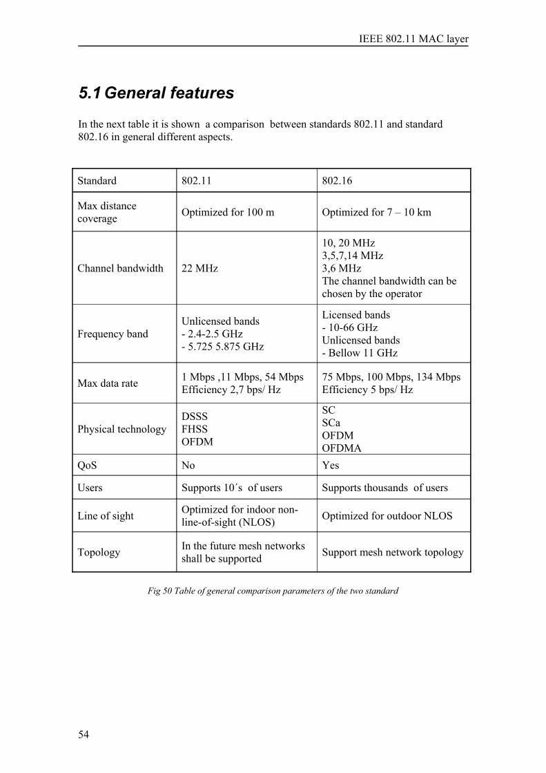
IEEE 802.11 MAC layer
5.1 General features
In the next table it is shown a comparison between standards 802.11 and standard802.16 in general different aspects.
Standard 802.11 802.16
Max distancecoverage Optimized for 100 m Optimized for 7 – 10 km
Channel bandwidth 22 MHz
10, 20 MHz3,5,7,14 MHz3,6 MHzThe channel bandwidth can bechosen by the operator
Frequency bandUnlicensed bands - 2.4-2.5 GHz - 5.725 5.875 GHz
Licensed bands- 10-66 GHzUnlicensed bands- Bellow 11 GHz
Max data rate 1 Mbps ,11 Mbps, 54 MbpsEfficiency 2,7 bps/ Hz
75 Mbps, 100 Mbps, 134 MbpsEfficiency 5 bps/ Hz
Physical technologyDSSSFHSSOFDM
SCSCaOFDMOFDMA
QoS No Yes
Users Supports 10´s of users Supports thousands of users
Line of sight Optimized for indoor non-line-of-sight (NLOS) Optimized for outdoor NLOS
Topology In the future mesh networksshall be supported Support mesh network topology
Fig 50 Table of general comparison parameters of the two standard
54
IEEE 802.11 MAC layer
5.2 MAC layer of the two standards
If we watch the upper layer of the 802.11 MAC, immediately is found the LLC sublayer(see 1.2 ), that characteristic makes 802.11 protocol seems to networks layers like anetwork based in Ethernet, this feature relieves complexity to network layer protocols,and make a perfect insertion in the previous protocol architecture. Like was explainingthe introduction the LLC provide an extra reliable functions to 802.11, with their threedifferent services, and ARQ mechanism.
In the other hand the standard 802.16 MAC treats directly with upper network layers,for solving this situation the 802.16 introduce a sublayer, Service-SpecificConvergence sublayer (CS)(see ), that provides any transformation or mapping ofexternal network data. As consequence the MAC layer is composed by three differentsublayers. The main sublayer is the MAC common Part Sublayer which is connectedwith the CS through the MAC SAP. The third sublayer, Security Sublayer, is locatedbelow the MAC common Part Sublayer and it is a small sublayer. It is not necessary aSAP between them. Below the Security Sublayer, or if it is preferred, below the MAClayer it is found the Physical Layer, both Layers are connected through the PHY SAP.
Below the 802.11 MAC layer (see 1.4) there may be different physical layers, formaking understandable the MAC with different transmission techniques, it is introduceda convergence sublayer only with the objective of comprehension.
In the previous overview it was repassed the layers around the 802.11 MAC layer andthe 802.16 MAC common Part Sublayer, with this glance, the proper Mac layer of thetwo standards were located in the stack of protocols involved in wirelesscommunications. For finishing with the comparison it is going to insert within the ownmechanisms of this layer. The main aspects of these MAC layers are as follows.
5.2.1 Topologies
In the standard 802.16 are distinguished two different topologies; PMP and Mesh modealthough for the research only Mesh mode has been studied. This Mesh mode iscomposed by Stations with the same importance. Only the station connected to thebackhaul services outside the Mesh network is defined different, it is termed Mesh BaseStation. All the Station included the Mesh BS can transmit each other. The point ofinterest of Mesh mode has been the Distributed Scheduling since it was seek a mannerto manage the Network without a central or manager node, been a more flexibleconfiguration if one node is moving out.In the standard 802.11 the configuration that make good with this requirement is theIndependent Basic Service Set topology, the great disadvantages with 802.16 is that802.11 protocol is not allowed more than one hop, if the stations has not direct sight,there aren’t a routing protocol that saves this situation, therefore the communication willnot possible between this stations.
55
IEEE 802.11 MAC layer
5.2.2 Initiation and Synchronization
The initiation and synchronization of the ad hoc 802.11 network or the greeting to thenew station is a process that it is resumed in four steps; scanning for BSSs, initiatingBSSs, joining to an IBSS and timing synchronization. In contrast the process ofinitialization in Mesh mode is fairly complex . While the new node is receiving differentpackets from the network, it must construct the physical neighbor list . In addition thenew node has to ask a regular node to be its Sponsor node, this supposes that the newnode must process a large amount of information. In both cases, during the initialization, the node must acquire synchronization with theothers in order to know about the other transmissions.
5.2.3 Channel separation
In the 802.11 control and management frames and the data frames share the samechannel, they compete for the use of the channel . Unlike 802.11, the control and datachannel are separated in the standard 802.16. The Mesh frame is divided into twosubframes : Control subframe and Data subframe. This separation of the subframes isrealized in order to provide coordination to the Network.
5.2.4 Overall transmission scheme
In the standard 802.11 the stations use a “listen before send” mechanism. At the sametime in order to decrease the possibility of beginning the transmission at the same timetwo stations use a backoff procedure , that introduces some dead times in the use of themedium. This derives in a disadvantage. On the other hand the IEEE 802.16 is a slottedsystem where all the transmission must be synchronized, that supposes the station doesnot require to sense the channel since it has assigned some slots for transmitting. Withthese restrictions the transmission of control messages are scheduled in a collision freemanner.
5.2.5 Collision avoidanceThe standard 802.11implement a medium access technique to avoid the collisions,CSMA/CA, with the introduction of two control frames RTS/CTS in the basic sequenceof transmission achieves reduce the collisions that the known hidden problem cause.
As it has been mentioned in the previous point, the standard 802.16 avoids the collisionsby using a slotted frame. At the same time Distributed Scheduling uses a three-wayhandshaking to set up connection before data. As well as the standard 802.11 with theintroduction of medium access technique to avoid the collisions, CSMA/CA, with twocontrol frames RTS/CTS in the basic sequence of transmission achieves reduce thecollisions that the known hidden problem cause. The difference between bothmechanisms may be that in standard 802.16 the aim is avoiding the collision and instandard 802.11 it is enough with reducing the collisions.
56
IEEE 802.11 MAC layer
5.2.6 Competing for data transmission
Another major difference is that in standard 802.16 multiple slots are reserved by thenode for exchanging control messages. However each node in their eligible transmissionopportunity must compete with others eligible competing nodes for transmitting theircorresponding packets. The winner node is chosen by using the Distributed electionAlgorithm. Whereas in 802.11 must compete for the channel for every packet andamong all of them.
5.2.7 Construction of MAC PDUs
This is one of the most important features of the MAC layer. In the construction ofMAC PDUs it can be seen how efficiency is the use of the offered capacity for payload.Both standards 802.11 and 802.16 are similar in the aspect that both use fragmentationand CRC with the difference that Mesh mode requires fragmentation subheaders whenfragmentation is presented. However the main difference is that standard 802.16 mayuse packing. By using packing the PDU can be used in a better manner in the case ofreceiving from upper layers a SDU small enough to insert more than one in the samePDU. In the standard 802.11 the fragmentation serve to the propose of fit the packets tothe size of the physical layer frames, furthermore increase the transmit reliability in thepresence of interference.
5.2.8 Error recovery mechanism
The 802.11 MAC layer provides an error recovery mechanism with retransmissionprocedure, it is an automatic repeat-request (ARQ). This is implemented with thesupport of ACK responses from the receiver. Furthermore a lifetime is assigned to thefragments, after this period the frames will be discard. In the standard 802.16 theimplementation of ARQ mechanism is optional. But when it is implemented it providesa complete ARQ mechanism. It uses sliding window and as in the case of 802.11 alifetime is assigned to the fragments.
57
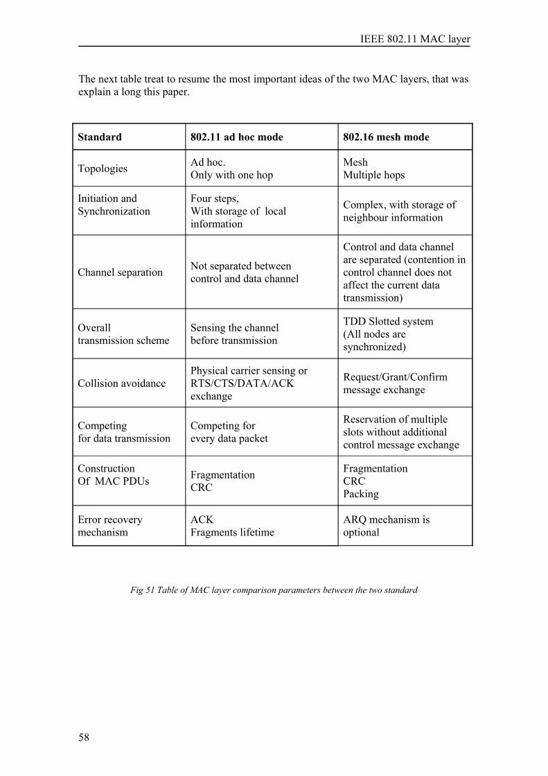
IEEE 802.11 MAC layer
The next table treat to resume the most important ideas of the two MAC layers, that wasexplain a long this paper.
Standard 802.11 ad hoc mode 802.16 mesh mode
Topologies Ad hoc.Only with one hop
MeshMultiple hops
Initiation andSynchronization
Four steps,With storage of localinformation
Complex, with storage ofneighbour information
Channel separation Not separated between control and data channel
Control and data channelare separated (contention incontrol channel does notaffect the current datatransmission)
Overall transmission scheme
Sensing the channelbefore transmission
TDD Slotted system(All nodes aresynchronized)
Collision avoidancePhysical carrier sensing orRTS/CTS/DATA/ACKexchange
Request/Grant/Confirmmessage exchange
Competingfor data transmission
Competing for every data packet
Reservation of multipleslots without additionalcontrol message exchange
ConstructionOf MAC PDUs Fragmentation
CRC
Fragmentation CRCPacking
Error recovery mechanism
ACKFragments lifetime
ARQ mechanism isoptional
Fig 51 Table of MAC layer comparison parameters between the two standard
58
IEEE 802.11 MAC layer
6 Conclusions and future work
6.1 Conclusions
The objective at begin of this investigation was to search for information of all themechanism that 802.11 Mac provide in at ad hoc configuration. It was dedicated specialattention to the start process of a new station in independent BSS mode, it was describeevery frame that is transmitted over the medium, the positive aspect is the lack of acentral station or coordinator, that provides a great independent and flexibility, thedeficit of multi hop is the biggest deficiency of the network configuration, other weakaspect is the lack of storage information about other stations information.
The second great issue that treats the MAC layer is the way to access the medium, andsolve the problems that carry a shared and unlicensed medium, the 802.11 ca not detectcollision, for solve this treat to avoid the maximum number of collision with aCSMA/AC protocol that is the core of the MAC. It fits perfectly in an Ethernet typenetwork, it reduces the number of changes necessary in this networks. The controlinformation that introduces the MAC layer could be reduced adjust the thresholdparameter, the same that the fragmentation level of the network.
6.2 Open issues and future work
After this study several issues could be investigated in the future, there are twochallenges that could changes the MAC structure, the first is try to study the advantagesof separate the control information in a different channel from the data channel, it couldlabel single channel against multiple channels. The other would be to introduce aarchitecture that allow the existence of multiple hops, that distinguish like the bigopportunity for a real useful of ad hoc networks.
Other issue could be the study of fairness schemes, in situation of competition amongstations, trying to improve the fairness of the actual MAC layer contention layer.
Immediately finished the theoretic study of this networks, it would be very usefulimplement a ad hoc simulation model.
The last issue in all study is performance measurements in a real situation that give aappreciation of the possibilities of this protocol in live test.
59
IEEE 802.11 MAC layer
In connection with this paper there are two IEEE task that are working in thedevelopment of two new standards that improves some of the topic that was told alongthe antecedent chapters and could be interesting:
• Task Group S and the proximate standard “IEEE 802.11s Extended Service SetMesh networking”, it’s supposed to be ready for the early 2007, and willcontribute with a mesh networking extension, and it will facilitate the possibilityof multi-hop 802.11 networks, auto configuration features and auto-discovery ofevery station.
• Task Group N will publish a new standard with the next designation 802.11n,and is known like MIMO PHY (multiple-input/multiple-output) or the High-Throughput PHY 802.11 standard. This new standard will not change the MAClayer on his core, it will focus on the physical layer, with the introduction of newtechniques like simultaneous receiver processing, and breaking up the singleframes and multiplexed across multiple spatial streams, with the consequentialreassembled at the receiver. It’s going to be compatible with the originalstandard, with the coexistence of other wireless networks.
Other organization the Internet Engineering Task Force IETF in his investigation areaof Mobile ad hoc networks ( MANET) is studying the development of dynamic routingprotocols that can efficiently look for intermediate stations in the communicationbetween two stations members of an ad hoc networks.
60
IEEE 802.11 MAC layer
7 Abbreviations
ACK acknowledgmentAP access pointARQ automatic repeat requestATIM announcement traffic indication messageBSA basic service areaBSS basic service setBSSID basic service set identificationCCA clear channel assessmentCDMA code division multiple accessCF contention freeCFP contention-free periodCP contention periodCRC cyclic redundancy codeCS carrier senseCSMA/CA carrier-sense multiple access with collision avoidanceCTS clear to sendCW contention windowDA destination addressDCF distributed coordination functionDIFS distributed (coordination function) interframe spaceDLL data link layerDS distribution systemDSAP destination service access pointDSS distribution system serviceDSSS direct sequence spread spectrum
61
IEEE 802.11 MAC layer
DTIM delivery traffic indication messageEIFS extended interframe spaceERP extended rate physicalERS extended rate setESA extended service areaESS extended service setFC frame controlFCS frame check sequenceFH frequency hoppingFHSS frequency-hopping spread spectrumIBSS independent basic service setIDU interface data unitIETF Internet engineering task forceIFS interframe spaceIR infraredISM industrial, scientific, and medicalIV initialization vectorLAN local area networkLLC logical link controlLME layer management entityLRC long retry countMAC medium access controlMANET mobile ad-hoc networksMIB management information baseMLME MAC sublayer management entityMMPDU MAC management protocol data unitMPDU MAC protocol data unitMSDU MAC service data unitN/A not applicableNAV network allocation vectorPC point coordinatorPCF point coordination functionPDU protocol data unitPHY physical (layer)PHY-SAP physical layer service access pointPIFS point (coordination function) interframe spacePLCP physical layer convergence protocolPLME physical layer management entityPMD physical medium dependentPMD-SAP physical medium dependent service access pointPPDU PLCP protocol data unitPS power save (mode)RA receiver addressRF radio frequencyRTS request to sendRX receive or receiverSA source addressSAP service access pointSDU service data unitSIFS short interframe space
62
IEEE 802.11 MAC layer
SLRC station long retry countSME station management entitySMT station managementSRC short retry countSS station serviceSSAP source service access pointSSID service set identifierSSRC station short retry countSTA stationTA transmitter addressTBTT target beacon transmission timeTIM traffic indication mapTSF timing synchronization functionTU time unitTX transmit or transmitterWAN wide area networkWDM wireless distribution mediaWDS wireless distribution systemWEP wired equivalent privacyWIMAX worldwide Interoperability for Microwave AccessWLAN wireless Local Area NetworkWM wireless medium
63

IEEE 802.11 MAC layer
64
IEEE 802.11 MAC layer
8 References
[1] Going wi-fi. Janice Reynolds CMP books 2003
[2] 802.11 Wireless Networks The Definitive Guide Matthew Gast O´Reilly.2005
[3] Wi-Fi Handbook: Building 802.11b Wireless Networks by FrankOhrtman and Konrad Roeder McGraw-Hill © 2003
[4] 802.11 Wireless LAN Fundamentals By Pejman Roshan , Jonathan Leary ciscopress
[5] 802.11 WLANs and IP Networking Security, QoS, and Mobility Anand R. PrasadNeeli R. Prasad Artech House
[6] 802.11 Wireless Network Site Surveying and Installation By Bruce E. AlexanderCisco Press 2004
[7] Wireless LANs implementing High Performance IEEE 802.11 Networks. JIM Geier
[8] OFDM wireless LAN’s: A theoretical and practical guide. Juha heiskala, Johu Terry.SAMs
[9] IEEE 802.11 Wireless Local Area Networks. Brian P. Crow, Indra Widjaja,Jeong Geun Kim, Prescott T. Sakai. IEEE Communications Magazine • September 1997
[10] Investigation of IEEE standard 802.16 Medium Access Control (MAC) layer inDistributed Mesh Networks and comparison with IEEE 802.16 ad-hoc networks. PedroFrancisco Robles Rico, May 2006.
http://www.ieee802.org/11/http://www.wi-fi.org/www.efis.dk European frequency information systemwww.ero.dk European radiocomnications officewww.eto.dk European telecommunications office
65
På svenska
Detta dokument hålls tillgängligt på Internet – eller dess framtida ersättare – under en längre tid från publiceringsdatum under förutsättning att inga extraordinära omständigheter uppstår.
Tillgång till dokumentet innebär tillstånd för var och en att läsa, ladda ner, skriva ut enstaka kopior för enskilt bruk och att använda det oförändrat för ickekommersiell forskning och för undervisning. Överföring av upphovsrätten vid en senare tidpunkt kan inte upphäva detta tillstånd. All annan användning av dokumentet kräver upphovsmannens medgivande. För att garantera äktheten, säkerheten och tillgängligheten finns det lösningar av teknisk och administrativ art. Upphovsmannens ideella rätt innefattar rätt att bli nämnd som upphovsman i den omfattning som god sed kräver vid användning av dokumentet på ovan beskrivna sätt samt skydd mot att dokumentet ändras eller presenteras i sådan form eller i sådant sammanhang som är kränkande för upphovsmannens litterära eller konst-närliga anseende eller egenart.
För ytterligare information om Linköping University Electronic Press se förlagets hemsida http://www.ep.liu.se/
In English
The publishers will keep this document online on the Internet -or its possible replacement -for a considerable time from the date of publication barring exceptional circumstances.
The online availability of the document implies a permanent permission for anyone to read, to download, to print out single copies for your own use and to use it unchanged for any non-commercial research and educational purpose. Subsequent transfers of copyright cannot revoke this permission. All other uses of the document are conditional on the consent of the copyright owner. The publisher has taken technical and administrative measures to assure authenticity, security and accessibility.
According to intellectual property law the author has the right to be mentioned when his/her work is accessed as described above and to be protected against infringement.
For additional information about the Linköping University Electronic Press and its procedures for publication and for assurance of document integrity, please refer to its WWW home page: http://www.ep.liu.se/
© [Författarens för- och efternamn] Fernando García Torre