Embed Size (px)
Citation preview
Before using your air conditioner, please read
this manual carefully and keep it for future reference.
ROOM AIR CONDITIONER
Please read this installation manual completelybefore installing the product.If the power cord is damaged, replacement workshall be performed by authorised personnel only.Installation work must be performed in accordancewith the national wiring Standards by authorisedpersonnel only.Contact an authorised service technician forrepair, maintenance or installation of this unit.
INVERTER ONE-TWO / ONE-THREE/ONE- FOUR SPLIT-TYPE

1
CONTENTS
SAFETY PRECAUTIONSWarning ...........................................................................................................................................2Caution ............................................................................................................................................2
INSTALLATION INSTRUCTIONS
Selecting installation place...............................................................................................................3Wall-mounted type ...........................................................................................................................3Accessories ... . . . . . . . . . . . . . . . . . . . . . . . . . . . . . . . . . . . . . . . . . . . . . . . . . . . . . . . . . . . . . . . . . . . . . . . . . . . . . . . . . . . . . . . . . . . . . . . . . . . . . .4Four-way cassette type ................................................................................................................9Duct & Ceiling type .......................................................................................................................12Ceiling and Floor type ....................................................................................................................16Floor and Standing type(Console)..................................................................................................19Outdoor unit installation ................................................................................................................23
REFRIGERANT PIPE CONNECTIONRefrigerant pipe connection ..........................................................................................................24
Inside you will find many helpful hints on how to install and test the air conditioner properly.
Contact an authorised service technician for repair or maintenance of this unit.Contact an authorised installer for installation of this unit.The air conditioner is not intended for use by young children or infirmed persons without supervision.Young children should be supervised to ensure that they do not play with the air conditioner.If the power cord is to be replaced, replacement work shall be performed by authorised personnel only.Installation work must be performed in accordance with the national wiring Standards by authorisedpersonnel only.
All the illustrations and specifications in the manual are subject to change without prior notice for productimprovement. The actual shape should prevail.
CAUTION
Read This Manual
ELECTRICAL WORKElectrical work .................. ...........................................................................................................25
TEST RUNNINGTest running ..................................................................................................................................31
AIR PURGINGAir purging with vacuum pump .....................................................................................................28Safety and leakage check ............................................................................................................30
2
SAFETY PRECAUTIONS
WARNING
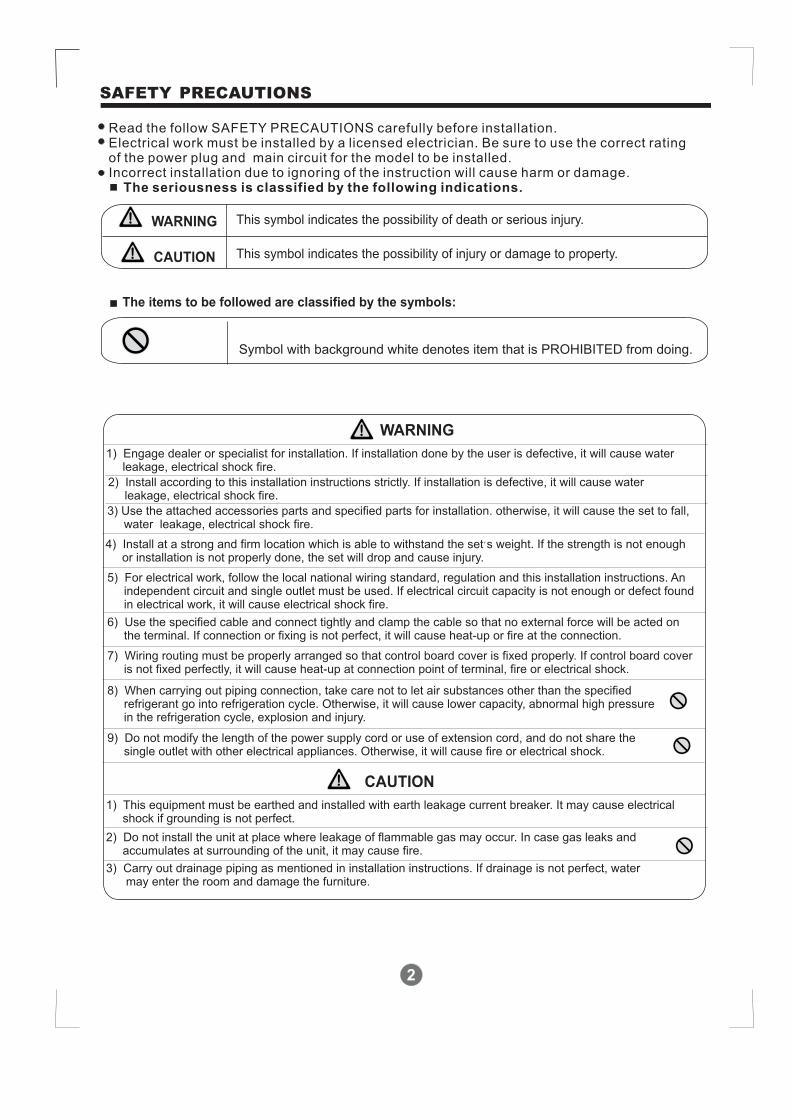
Read the follow SAFETY PRECAUTIONS carefully before installation.Electrical work must be installed by a licensed electrician. Be sure to use the correct ratingof the power plug and main circuit for the model to be installed.Incorrect installation due to ignoring of the instruction will cause harm or damage.
The seriousness is classified by the following indications.
This symbol indicates the possibility of death or serious injury.
The items to be followed are classified by the symbols:
Symbol with background white denotes item that is PROHIBITED from doing.
CAUTION This symbol indicates the possibility of injury or damage to property.
WARNING
1) Engage dealer or specialist for installation. If installation done by the user is defective, it will cause waterleakage, electrical shock fire.
2) Install according to this installation instructions strictly. If installation is defective, it will cause waterleakage, electrical shock fire.
3) Use the attached accessories parts and specified parts for installation. otherwise, it will cause the set to fall,water leakage, electrical shock fire.
4) Install at a strong and firm location which is able to withstand the set s weight. If the strength is not enoughor installation is not properly done, the set will drop and cause injury.
,
5) For electrical work, follow the local national wiring standard, regulation and this installation instructions. Anindependent circuit and single outlet must be used. If electrical circuit capacity is not enough or defect foundin electrical work, it will cause electrical shock fire.
6) Use the specified cable and connect tightly and clamp the cable so that no external force will be acted onthe terminal. If connection or fixing is not perfect, it will cause heat-up or fire at the connection.
7) Wiring routing must be properly arranged so that control board cover is fixed properly. If control board coveris not fixed perfectly, it will cause heat-up at connection point of terminal, fire or electrical shock.
8) When carrying out piping connection, take care not to let air substances other than the specifiedrefrigerant go into refrigeration cycle. Otherwise, it will cause lower capacity, abnormal high pressurein the refrigeration cycle, explosion and injury.
9) Do not modify the length of the power supply cord or use of extension cord, and do not share thesingle outlet with other electrical appliances. Otherwise, it will cause fire or electrical shock.
CAUTION
1) This equipment must be earthed and installed with earth leakage current breaker. It may cause electricalshock if grounding is not perfect.
2) Do not install the unit at place where leakage of flammable gas may occur. In case gas leaks andaccumulates at surrounding of the unit, it may cause fire.
3) Carry out drainage piping as mentioned in installation instructions. If drainage is not perfect, watermay enter the room and damage the furniture.
3
Selecting installation place
Read completely, then follow step by step.
Indoor unit
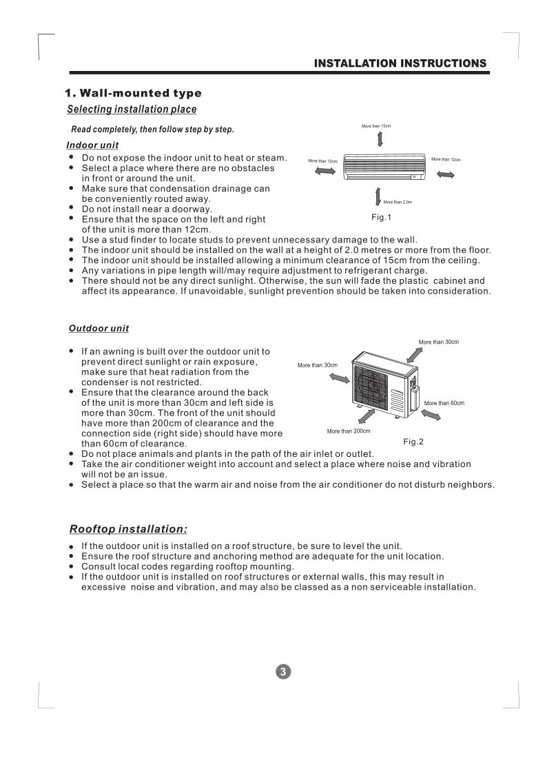
Do not expose the indoor unit to heat or steam.Select a place where there are no obstaclesin front or around the unit.Make sure that condensation drainage canbe conveniently routed away.Do not install near a doorway.Ensure that the space on the left and rightof the unit is more than 12cm.Use a stud finder to locate studs to prevent unnecessary damage to the wall.The indoor unit should be installed on the wall at a height of 2.0 metres or more from the floor.The indoor unit should be installed allowing a minimum clearance of 15cm from the ceiling.Any variations in pipe length will/may require adjustment to refrigerant charge.There should not be any direct sunlight. Otherwise, the sun will fade the plastic cabinet andaffect its appearance. If unavoidable, sunlight prevention should be taken into consideration.
Outdoor unit
If an awning is built over the outdoor unit toprevent direct sunlight or rain exposure,make sure that heat radiation from thecondenser is not restricted.Ensure that the clearance around the backof the unit is more than 30cm
. The front of the unit shouldhave more than 200cm of clearance and theconnection side (right side) should have morethan 60cm of clearance.Do not place animals and plants in the path of the air inlet or outlet.Take the air conditioner weight into account and select a place where noise and vibrationwill not be an issue.Select a place so that the warm air and noise from the air conditioner do not disturb neighbors.
If the outdoor unit is installed on a roof structure, be sure to level the unit.Ensure the roof structure and anchoring method are adequate for the unit location.Consult local codes regarding rooftop mounting.If the outdoor unit is installed on roof structures or external walls, this may result inexcessive noise and vibration, and may also be classed as a non serviceable installation.
and left side ismore than 30cm
Rooftop installation:
INSTALLATION INSTRUCTIONS
More than 30cm
More than 60cm
More than 30cm
More than 200cm
Fig.2
More than 2.0m
More than 15cm
More than 12cmMore than 12cm
Fig.1
1. Wall-mounted type

4
Accessories
INSTALLATION INSTRUCTIONS
Note: Except the above parts provided, the other parts needed during installation you must
purchase.
Parts you mustpurchase(The minimum pipewall-thicknessof 0.7mm is required. )
6.35
9.53
12.7
8 2Self-tapping Screw B ST2.9X10
Remote controller
Installation Plate
Name of Accessories
Self-tapping Screw A ST3.9X25
Seal (See Page 8 for details)
Drain Joint
ConnectingpipeAssembly
Liquid side
Plastic Expansion Sheath
Number Q ty/one unit’
Gas side
9 Remote controller holder 1
( 12000Btu/h model)<
( 12000Btu/h model)≥
(See page 8 for details)
1
8
8
1
1
17
6
5
4
3
2
1
Level gaugeScrewdriverElectric drill,Hole core drill ( 65φ mm)Flaring tool setSpecified torque wrenches: 1.8kgf.m, 4.2kgf.m,5.5kgf.m, 6.6kgf.m(different depending on model No.)Spanner (half union)Hexagonal wrench (4mm)Gas-leak detector
Tools needed for installation:
Vacuum pumpGauge manifoldUsers manualThermometerMultimeterPipe cutterMeasuring tape
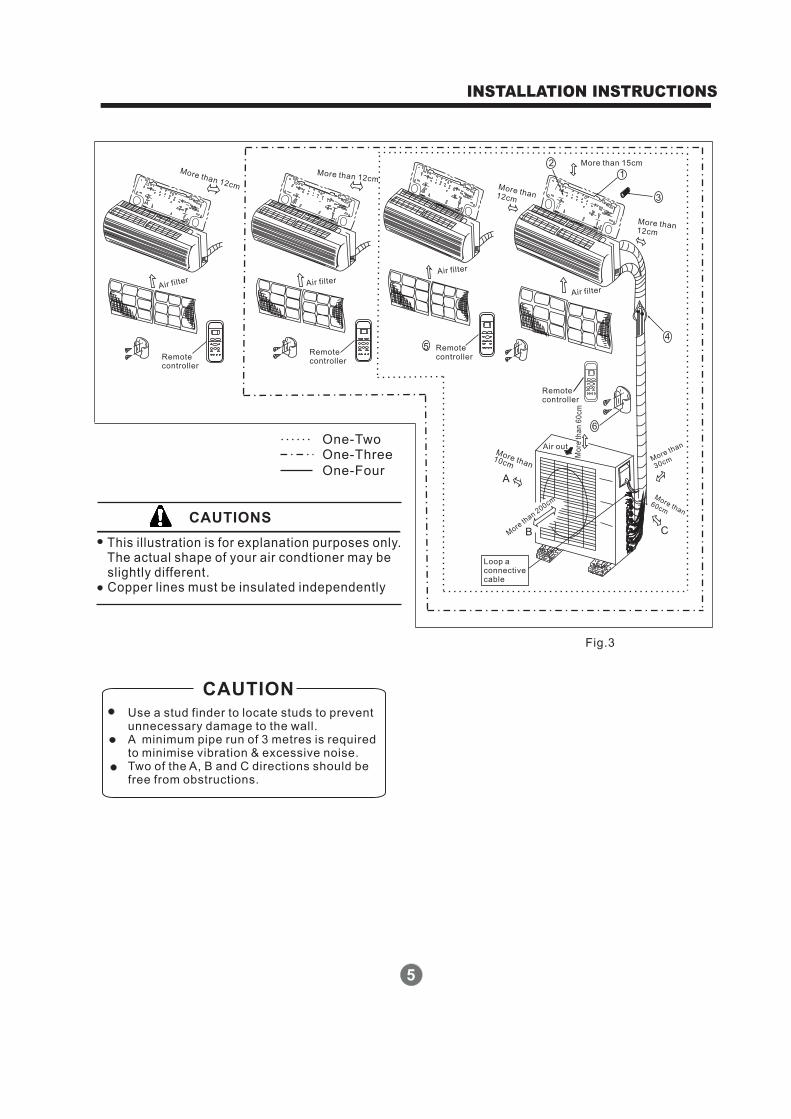
This illustration is for explanation purposes only.The actual shape of your air condtioner may beslightly different.Copper lines must be insulated independently
Use a stud finder to locate studs to preventunnecessary damage to the wall.A minimum pipe run of 3 metres is requiredto minimise vibration & excessive noise.Two of the A, B and C directions should befree from obstructions.
CAUTION
INSTALLATION INSTRUCTIONS
5
CAUTIONS
One-TwoOne-Three
One-Four
More than 12cm
Air filter
Remotecontroller
More than 12cm
Air filter
Remotecontroller
Remotecontroller
Air filter
More than12cm
More than 15cm
More than12cm
Air filter
Remotecontroller
More than10cm
A
B CMore
than 200cm
Air out
Mo
reth
an
60
cm
Morethan
30cm
More than60cm
Loop aconnectivecable
1
2
3
45
6
Fig.3
6
INSTALLATION INSTRUCTIONS
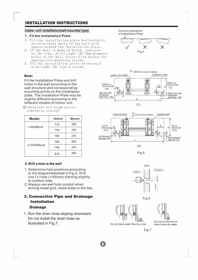
Fig.4
Correct orientationof Installation Plate
Wall
IndoorOutdoor
5-7
mm
Fig.6
Fig.5
Indoor unit installation(wall-mounted type)
2. Drill a hole in the wall
Note:
1. Fit the Installation Plate
1. Fit the installation plate horizontallyon structural parts of the wall withspaces around the installation plate.
2. If the wall is made of brick, concreteor the like, drill eight (8) 5mm diameterholes in the wall.Insert Clip anchor forappropriate mounting screws.
3. Fit the installation plate on the wallwith eight (8) type A screws.
Fit the Installation Plate and drillholes in the wall according to thewall structure and correspondingmounting points on the installationplate. The Installation Plate may beslightly different according to thedifferent models of indoor unit.
(Dimensions are in mm unlessotherwise stated)
1. Determine hole positions accordingto the diagramdetailed in Fig.5. Drillone (1) hole ( 65mm) slanting slightlyto outdoor side.
2. Always use wall hole conduit whendrilling metal grid, metal plate or the like.
φ
3. Connective Pipe and Drainage
Installation
1. Run the drain hose sloping downward.
Do not install the drain hose as
illustrated in Fig.7.
Drainage
Fig.7
Do not block water flow by a rise.Do not put the end ofdrain hose into water.
A
40
B
Right rear siderefrigerantpipe hole 65φ
Installation plateIndoor unit outline
Left rear siderefrigerantpipe hole 65φ
150mm or more to ceiling
120mm ormore to wall120mm or
more to wall 90
40
45
Model A(mm)
710
B(mm)
250<12000Btu/h
790 265
815 280
>12000Btu/h
780 270
780 270
750 250
Indoor unit outline
12cm ormore to wall
12cm ormore to wall
Left refrigerantpipe hole 65φ Right refrigerant
pipe hole 65φ
Installation plate
A
45
B
15cm or more to ceiling
45 96
45
(1)
(2)

7
INSTALLATION INSTRUCTIONS
1. For the left-hand and right-hand piping,remove the pipe cover from the sidepanel.
2. For the rear-right-hand and rear-left-handpiping, install the piping as shown in Fig.9.Bend the connective pipe to be laid at 43mmheight or less from the wall.
3. Fix the end of the connective pipe. (Referto Tightening Connection in REFRIGERANTPIPING CONNECTION)
Connective pipe installation
2. When connecting extension drain hose,insulate the connecting part of extensiondrain hose with a shield pipe, do not letthe drain hose slack.
Right-hand piping
Left-hand piping
Rear-right piping
Rear-left piping
Indoor unit outline Connective pipe
........ ...
..
.
..
. ..
.. ..
...
..
. ...
. .
... .
..
....
.... ..
. .
..
. ... .
. . .
....
. ... .
...
. ... .
...
...
..
. ...
.
.
... .
..
....
...
. ...
..
... .
..
. ... .
.
.
.
..
..
.
.
..
.
.
.
.
. . ..
...
.
.........
.
43
Fig.8
Fig.9
Fig.10
4. Piping and wrapping
Bundle the tubing, connecting cable, and drainhose with tape securely, evenly as shown inFig.11.
Because the condensed water from rear of theindoor unit is gathered in ponding box and ispiped out of room. Do not put anything else inthe box.
Indoor unit
Connective
pipe
Pipe room
Ponding box
Wrapping belt
Connective
cable
Drain hose
..
...
..
.....
.....
...
.......
..
. .
.
Fig.11
Connect the indoor unit first, then theoutdoor unit.Do not allow the piping to let out fromthe back of the indoor unit.Be careful not to let the drain hose slack.Heat insulated both of the auxiliary piping.Be sure that the drain hose is located atthe lowest side of the bundle. Locatingat the upper side can cause drain panto overflow inside the unit.Never intercross nor intertwist the powerwire with any other wiring.Run the drain hose sloped downward todrain out the condensed water smoothly.
CAUTION
8
INSTALLATION INSTRUCTIONS
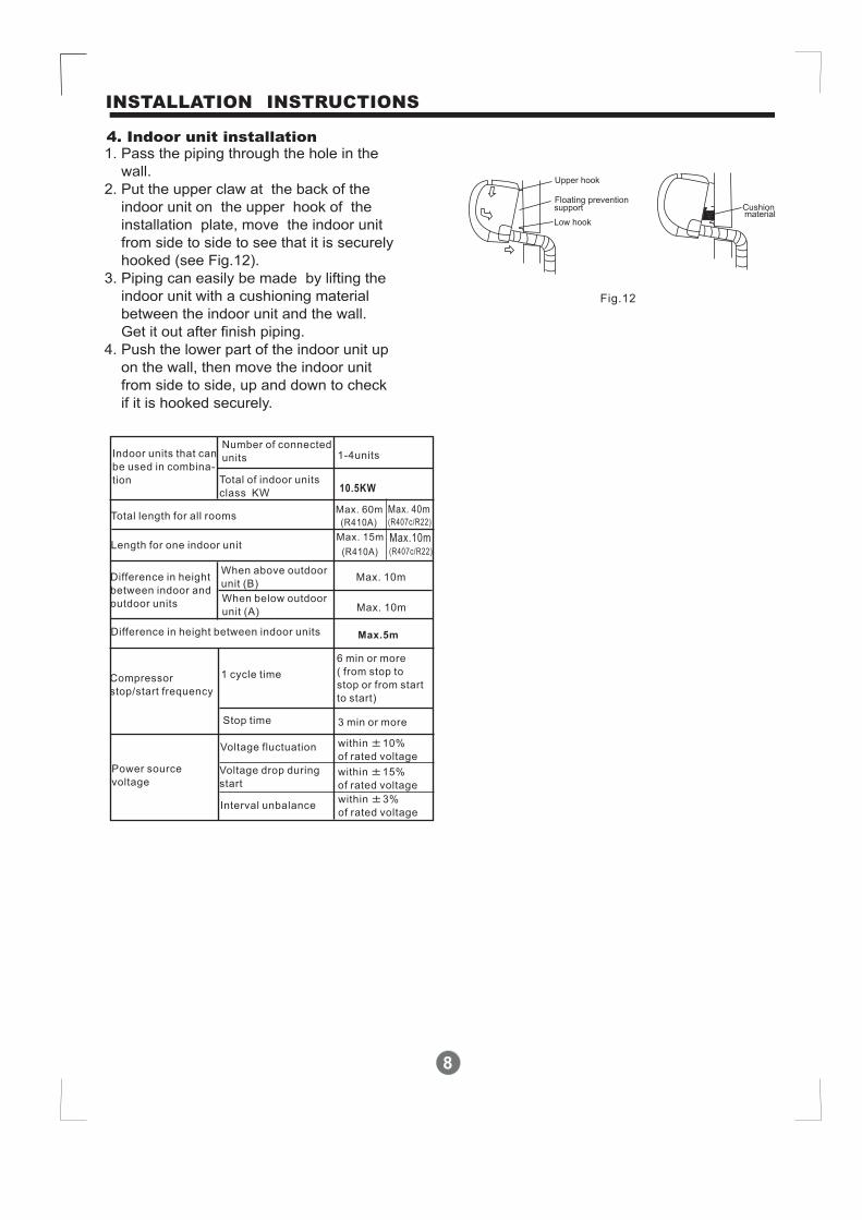
Fig.12
1. Pass the piping through the hole in the
wall.
2. Put the upper claw at the back of the
indoor unit on the upper hook of the
installation plate, move the indoor unit
from side to side to see that it is securely
hooked (see Fig.12).
3. Piping can easily be made by lifting the
indoor unit with a cushioning material
between the indoor unit and the wall.
Get it out after finish piping.
4. Push the lower part of the indoor unit up
on the wall, then move the indoor unit
from side to side, up and down to check
if it is hooked securely.
4. Indoor unit installation
(R410A)
Max. 40m(R407c/R22)
Max.10m
Max.5m
(R410A) (R407c/R22)
10.5KW

2. Four-way cassette type
1. Decide the correct carry-in path.2. Move this unit as originally packaged as possible.3. If the air conditioner is installed on a metal part
of the building, it must be electrically insulatedaccording to the relevant electrical code.
4. If installing in a lonely building or at a high positionwhere it is hot and humid with frequent thunder-storm, lightning-protection equipment is necessary.
Notes before installation
1. Install the main body
A. The existing ceiling (to be horizontal)a. Please cut a quadrangular hole of 600 600mm
in the ceiling according to the shape of theinstallation paper board. (Refer to Fig.15 & 16)The center of the hole should be at the sameposition of that of the air conditioner body.Determine the lengths and outlets of the conn-ecting pipe, drain pipe and cables.To balance the ceiling and to avoid vibration,please enforce the ceiling when necessary.
b. Please select the position of installation hooksaccording to the hook holes on the installationboard.Drill four holes of 12mm, 50~55mm deep at theselected positions on the ceiling. Then embedthe expansible hooks(fittings).Face the concave side of the installation hookstoward the expansible hooks. Determine thelength of the installation hooks from the heightof ceiling, then cut off the unnecessary part.If the ceiling is extremely high, please determinethe length of the installation hook according tofacts.Cut the installation hook open in the middleposition, then use apropriate length of reinforcingrod ( 12) to weld together.
Indoor unit installation
9
INSTALLATION INSTRUCTIONS
Please check whether the following fittings are of full scope. If there are some attached fittings free
from use, please restore them carefully.
Installation Fittings Tubing & Fittings
1. Expansible hook.................................4
2. Installation hook.................................4
3. Installation paper board.....................1
4. Bolt M6 12.....................4M5 16 or
Attached fittings
5. Connecting pipe group.........................1
7. Soundproof / insulation sheath.............2
6. Binding tape.........................................6
Remote controller & Its Frame
8 Remote controller............................1
9. Frame..............................................1
10. Mounting screw(ST2.9 10-C-H) ...2
11. Alkaline dry batteries (AM4)............2
12. Outdoor/indoor unit signal wire............1
A28
0
Necessary roomNecessary room
Fig.13
Fig.14
Ground
OutletOutlet
>230
0
Inlet
>100
0
>1000
>1000 >1000
Fig.15
Drain side A
422 28.5
67
401(
Hoo
klo
catio
n)
611(Hook location)
580(
Bod
y)
580(Body)
600(
Cei
ling
hole
)
600(Ceiling hole)
650(
Pan
el)
650(Panel)
10
INSTALLATION INSTRUCTIONS
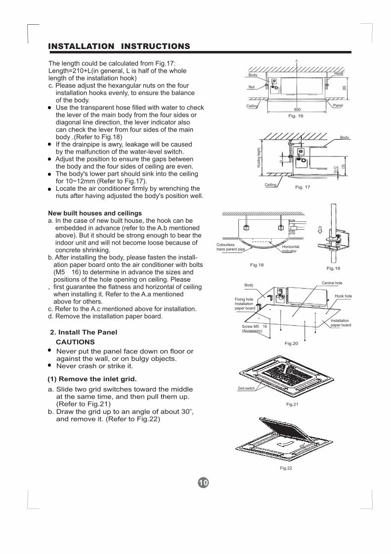
The length could be calculated from Fig.17:Length=210+L(in general, L is half of the wholelength of the installation hook)c. Please adjust the hexangular nuts on the four
installation hooks evenly, to ensure the balanceof the body.Use the transparent hose filled with water to checkthe lever of the main body from the four sides ordiagonal line direction, the lever indicator alsocan check the lever from four sides of the mainbody Refer to Fig.18)If the drainpipe is awry, leakage will be causedby the malfunction of the water-level switch.Adjust the position to ensure the gaps betweenthe body and the four sides of ceiling are even.The body's lower part should sink into the ceilingfor 10~12mm (Refer to Fig.17).Locate the air conditioner firmly by wrenching thenuts after having adjusted the body's position well.
.(
2. Install The Panel
(1) Remove the inlet grid.
CAUTIONS
Never put the panel face down on floor oragainst the wall, or on bulgy objects.Never crash or strike it.
a. Slide two grid switches toward the middleat the same time, and then pull them up.(Refer to Fig.21)
b. Draw the grid up to an angle of about 30 ,and remove it. (Refer to Fig.22)
o
New built houses and ceilingsa. In the case of new built house, the hook can be
embedded in advance (refer to the A.b mentionedabove). But it should be strong enough to bear theindoor unit and will not become loose because ofconcrete shrinking.
b. After installing the body, please fasten the install-ation paper board onto the air conditioner with bolts(M5 16) to determine in advance the sizes andpositions of the hole opening on ceiling. Please
, first guarantee the flatness and horizontal of ceilingwhen installing it. Refer to the A.a mentionedabove for others.
c. Refer to the A.c mentioned above for installation.d. Remove the installation paper board.
×
Fig. 16
Ceiling Panel
Hook
A
285Nut
Body
600
L
10-1
2 176
34
Fig. 17Ceiling
Body
H(c
eilin
ghe
ight
)
Fig.18Fig.19
Colourlesstrans parent pipe
Horizontalindicator
Fig.20
Body
Fixing holeInstallationpaper board
Screw M5 16(Accessory)
Installationpaper board
Hook hole
Central hole
Grid switch
Fig.21
45o
Fig.22

11
INSTALLATION INSTRUCTIONS
(2) Install the panel
(3) Hang the air-in grid to the panel, then connectthe lead terminator of the swing motor and thatof the control box with corresponding terminatorson the body respectively.
(4) Relocate the air-in grid in the procedure ofreversed order, install the air-in grid.
CAUTIONS:
a. Align the swing motor on the panel to the waterreceiver of the body properly. (Refer to Fig.23)
b. Hang the four fixed rope of the main body to theinstallation cover and the other three covers ofthe swing motor: (Refer to Fig.23 )
c. Install the panel on the main body with bolt (M5 16)and washer. (Refer to Fig.23)
d. Adjust the four panel hook screws to keep the panelhorizontal, and screw them up to the ceiling evenly.
e. Regulate the panel in the direction of the arrow inFig.11 slightly to fit the panel's center to the centerof the ceiling's opening. Guarantee that hooks offour corners are fixed well.
f. Keep fastening the screws under the panel hooks,until the thickness of the sponge between the bodyand the panel's outlet has been reduced to about4~6mm. The edge of the panel should contact withthe ceiling well. (Refer to Fig.24) Malfunctiondescribed in Fig.25 can be caused by inappropriatetightness the screw. If the gap between the paneland ceiling still exists after fastening the screws, theheight of the indoor unit should be modified again.You can modify the height of the indoor unit throughthe openings on the panel's four corners, if the lift ofthe indoor unit and the drainpipe is not influenced(refer to Fig.26-right).
The installation cover of the swing motor must sinkinto the corresponding water receiver.
..
Cover
Steel rope
Swing motor side
Swing motor installation cover
Drain side
Fig.23
Bolt, washer
2
4
3
1
Body
Panel foam2Ceiling
Panel foam
Air plate Panel Panel foam1
Panel sealing foamInlet air
Outlet air
Fig.24
Ceiling Leakage
Dew
Fig.25
Hexagon nut
Ceiling
Horizontal adjust ment
Fig.26
12
INSTALLATION INSTRUCTIONS
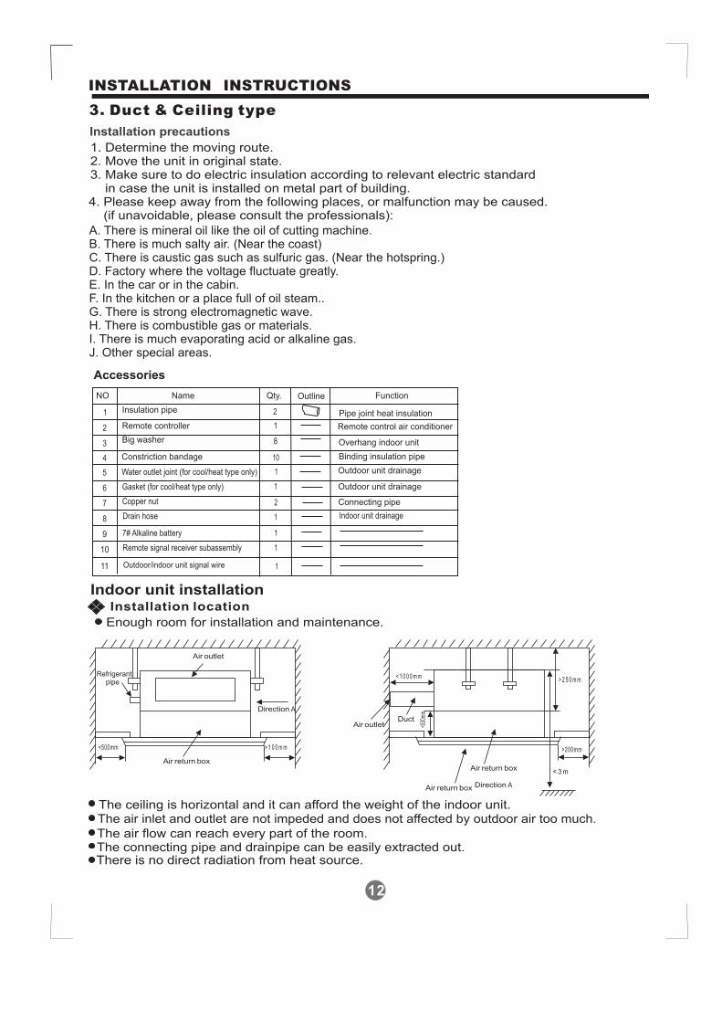
3. Duct & Ceiling type
Installation precautions
1. Determine the moving route.2. Move the unit in original state.3. Make sure to do electric insulation according to relevant electric standard
in case the unit is installed on metal part of building.
Indoor unit installation
Refrigerantpipe
Air outlet
Air return box
Direction A
<500mm
Duct
> 1 0 0 m m >200mm
> 2 5 0 m m
< 3 m
< 1 0 0 0 m m
4. Please keep away from the following places, or malfunction may be caused.(if unavoidable, please consult the professionals):
A. There is mineral oil like the oil of cutting machine.B. There is much salty air. (Near the coast)C. There is caustic gas such as sulfuric gas. (Near the hotspring.)D. Factory where the voltage fluctuate greatly.E. In the car or in the cabin.F. In the kitchen or a place full of oil steam..G. There is strong electromagnetic wave.H. There is combustible gas or materials.I. There is much evaporating acid or alkaline gas.J. Other special areas.
Enough room for installation and maintenance.
The ceiling is horizontal and it can afford the weight of the indoor unit.The air inlet and outlet are not impeded and does not affected by outdoor air too much.
The air flow can reach every part of the room.The connecting pipe and drainpipe can be easily extracted out.There is no direct radiation from heat source.
Installation location
Air return box
Air return box
Air outlet <500
mm
Direction A
Function
Insulation pipe
Remote controller
Big washer
Constriction bandage
Water outlet joint (for cool/heat type only)
Name Qty.NO Outline
1
2
3
4
5
6
7
8
2
1
8
Pipe joint heat insulation
Overhang indoor unit
Binding insulation pipe
Remote control air conditioner
9
10
Gasket (for cool/heat type only)
Copper nut
10
1
1
2 Connecting pipe
Outdoor unit drainage
Drain hose 1 Indoor unit drainage
Outdoor unit drainage
7# Alkaline battery
Remote signal receiver subassembly
1
1
Accessories
Outdoor/indoor unit signal wire11 1

13
INSTALLATION INSTRUCTIONS
Determine the location of hanging screw bolt following Fig.33.
Fig.27
Fig.28
Fig.30Fig.29
Installation of unit
Install 10 (4 pieces)hanging screw boltφ
Make sure to use the hanging screw bolt of 10.φ
The treatment to the ceiling varies from construction; please consult the professionals for details.1) Treatment to ceiling---make sure to consolidate the roof beam for possible vibration to keep the ceiling horizontal.2) Please cut off the roof beam.3) Reinforce the place that is cut off and consolidate the roof beam.Carry out connection of piping and wiring inside the ceiling.Determine the piping direction. Especially in the case of existing ceiling, please pull the wire to the connection place beforeoverhanging the unit.
Install the hanging bolt in following different situation:
Timber over the beam
(
)
Blade shapeinsertion
( )Slide insertion
Install with insertion or embedding screw.
Wooden structure
New concrete bricks
Put a timber across the beams and installthe bolts.
Hanging screw bolts
Ceiling
Roof beam
Steel bar
(Pipe hangingand embedding
screw bolt)
Original concrete bricks
Install the hanging hook with expansible
bolt into the concrete.
Steel roof beam structre
Install the supporting angle steel.Hanging screw bolt
Hanging bolts Supporting angl steele
Overhang the unit
Fig.31
Hanging screw bolt
Nut (upside)
Installation ear
Nut (underside)
Washer (upside)
Washer (underside)
Install the hanging screw bolt to theU-shaped slot of installation ear.Overhang the indoor unit and measurethe level degree of unit with a gradienter.
Fasten the nut
Gradienter
Fig.32
Fasten and fix the upside nut.

14
INSTALLATION INSTRUCTIONS
Air-in grille Air inlet
Fig.34a
Fig.33
The position of hanging bolts
21
0
10
2
25 CD
82
Air outlet (on side)
Air outlet sketch map
380
220
175
21
0
63
55
Water outlet,�25
Refrigerant piping jointgas side( )
A
B
26
8
38
5Fresh air inlet
Ceiling
>500mm
>250
mm
>500mm
148
100
A
B
�100
Refrigerant piping joint
(gas side)
Air-in grille Air inlet
Fig.34b
Air Inlet Panel of Air Return Box
Make the air inlet grille and air inlet direction
in parallel as shown in Fig. 34a.
Fig.34b is incorrect, which may cause loud noise.
CAUTION
Drainpipe installation
Piping, insulation material
Drainage
Heat insulation
Piping
Insulation material
Hard PVC pipe
Cellular polyethylene, thicker than 6mm
Please do heat insulation on piping joint.Bind the contact insulation part between theunit and installation location with bandage.
1. Indoor unit drainpipe installation
Fig.35
Fig.36
Hard PVC pipe
Heat insulationmaterial
Heat insulationmaterial
No space
Main unit
Seal theinsulation material
See Fig.35.
MODEL
<12000Btu/h
>12000Btu/h
A B C D
915
1260
870
1224
715
1015
870
1215

15
INSTALLATION INSTRUCTIONS
1.5m~2m
VP30
Fig.37
Fig.38
Fig.39
Fig.40
Fig.41
CAUTION
Refer to the figures on the right for the installationof pipes.
The drain pipe as well as the connection part ofindoor unit must be heat insulated, or condensatewill occur.
Please connect the pipe with horny PVC bondand make sure there is no leakage.
Do not impose the pressure on connectingpart of drainpipe.
The gradient downwards of drain pipe should beover 1/100, and do not bend the drain pipe.
Pull the drain pipe transversely within 20m. Pleaseinstall a supporter in case the drainpipe is verylong to prevent it from bending.
Lean Downward over 1/100
Supporting Unit
Fold
Bend
Lean Downwardover 1/100
As long as possible (10cm)
Name Qty. Outline/specification Function
Duct installationboard
8 Connecting duct
Fixation bolt (fixinginstallation board)
8 ST3.9 10-F-HFixing duct
installation board
Instructions for duct installation accessories
Duct design
Fix installation board
Make the duct as short as possible due to thelow static pressure (nearly 0 pa) of this unit.
Fix the installation board on duct outlet withthe bolts in accessories. If the bolt isself-provided, the length of bolt should beappropriate and make sure not to damage theinside of unit. See Fig.30
Duct installationFix the duct on installation board with rivet.See Fig.41.NOTE:1.Do not let the indoor unit bear the weight of duct.2.For convenient maintenance, install the duct
at the place where it is easy to do removing.3.In case doing installation in meeting room or
such places, please equip the interior withliner and muffler.
4.These accessories are optional. Please contactthe service for other requirement.
Accessories
16
INSTALLATION INSTRUCTIONS
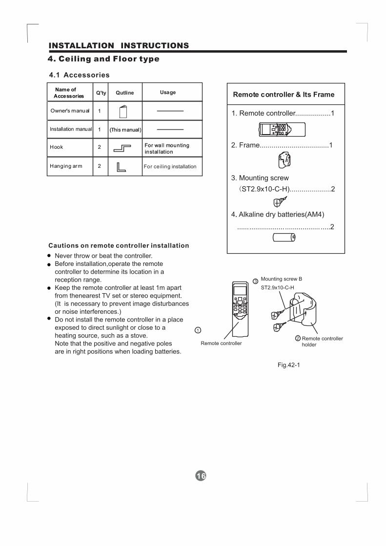
4. Ceiling and Floor type
4.1 Accessories
1
1
2
Name of
Accessories
Installation manual
Q'ty
(This manual)
Qutline Usage
Hook For wall mounting
instal lation
Hanging arm 2
1
1
2
Owner's manual
Q'ty
(This manual)
Qutline Usage
For wall mounting
instal lation
2 For ceiling installation
Fig.42-1
1. Remote controller..................1
2. Frame...................................1
3. Mounting screw
(ST2.9x10-C-H).....................2
4. Alkaline dry batteries(AM4).
...... .................. .................. .....2
Remote controller & Its Frame
1
2
3Mounting screw B
ST2.9x10-C-H
Remote controllerholderRemote controller
Never throw or beat the controller.
Before installation,operate the remote
controller to determine its location in a
reception range.
Keep the remote controller at least 1m apart
from thenearest TV set or stereo equipment.
(It is necessary to prevent image disturbances
or noise interferences.)
Do not install the remote controller in a place
exposed to direct sunlight or close to a
heating source, such as a stove.
Note that the positive and negative poles
are in right positions when loading batteries.
Cautions on remote controller installation
17
INSTALLATION INSTRUCTIONS
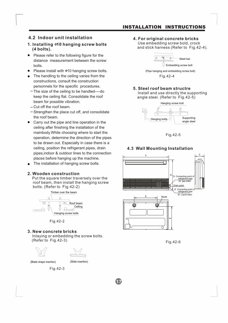
Please refer to the following figure for the
distance measurement between the screw
bolts.
Please install with 10 hanging screw bolts.
The handling to the ceiling varies from the
constructions, consult the construction
personnels for the specific procedures.
The size of the ceiling to be handled----do
keep the ceiling flat. Consolidate the roof
beam for possible vibration.
Cut off the roof beam.
Strengthen the place cut off, and consolidate
the roof beam.
Carry out the pipe and line operation in the
ceiling after finishing the installation of the
mainbody.While choosing where to start the
operation, determine the direction of the pipes
to be drawn out. Especially in case there is a
ceiling, position the refrigerant pipes, drain
pipes,indoor & outdoor lines to the connection
places before hanging up the machine.
The installation of hanging screw bolts.
4.2 Indoor unit installation
4.3 Wall Mounting Installation
1. Installing 10 hanging screw bolts(4 bolts).
2. Wooden constructionPut the square timber traversely over theroof beam, then install the hanging screwbolts. (Refer to Fig.42-2)
3. New concrete bricksInlaying or embedding the screw bolts.(Refer to Fig.42-3)
4. For original concrete bricksUse embedding screw bold, crockand stick harness (Refer to Fig.42-4).
5. Steel roof beam structreInstall and use directly the supportingangle steel. (Refer to Fig.42-5)
Hanging screw bolts
Ceiling
Timber over the beam
Roof beam
(Blade shape insertion) (Slide insertion)
Steel bar
Embedding screw bolt
(Pipe hanging and embedding screw bolt)
Fig.42-2
Fig.42-3
Fig.42-5
Fig.42-6
Fig.42-4
Hanging screw bolt
Hanging bolts Supporting
angle steel
E. Connecting point ofrefrigerant pipe
(D. gas side)
D. Connecting point ofrefrigerant pipe
(E. Liquid side)
Drain point
Hook
18
INSTALLATION INSTRUCTIONS
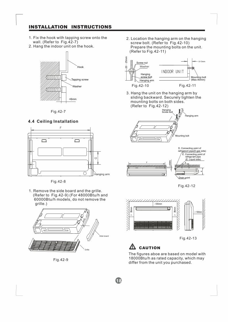
1. Fix the hook with tapping screw onto thewall. (Refer to Fig.42-7)
2. Hang the indoor unit on the hook.
2. Location the hanging arm on the hangingscrew bolt. (Refer to Fig.42-10)Prepare the mounting bolts on the unit.(Refer to Fig.42-11)
3. Hang the unit on the hanging arm bysliding backward. Securely tighten themounting bolts on both sides.(Refer to Fig.42-12)
1. Remove the side board and the grille.(Refer to Fig.42-9) (For 48000Btu/h and60000Btu/h models, do not remove thegrille.)
Washer
Tapping screw
Hook
<6mm
Fig.42-7
Fig.42-8
Fig.42-9
Fig.42-10
Fig.42-12
Fig.42-11
Fig.42-13
4.4 Ceiling Installation
Hanging arm
Side board
Grille
Screw nut
Hangingscrew bolt
Hanging arm
20
25
mm
~
Mounting bolt(Max.40mm)
8-13mm
Washer
Hanging arm
Mounting bolt
HangingScrew bolt
D. Connecting point of
refrigerant pipe(D.gas side)
Drain point
E. Connecting point ofrefrigerant pipe
≥35mm
≥1000mm
≥35
mm
≥35
mm
(E. Liquid side)
CAUTION
The figures aboe are based on model with18000Btu/h as rated capacity, which maydiffer from the unit you purchased.

19
INSTALLATION INSTRUCTIONS
4.5 The Dimension of the UnitUnit:mm
Capacity
12 18-
A B D E F G HC
990 660 206 505 506 907 200 203
Note:The dimension of 12000Btu/h and18000Btu/h are the same.
5. Floor and Standing Type
(Console)
5.1 Accessories(Console)
Please check whether the following fittingsare of full scope. If there are some sparefittings, please restore them carefully.
QUANTITYSHAPENAME
1.Hook
6. Owner's manual
7. Installation manual
2. Remote controller
3. Frame
5. Alkaline dry batteries
(AM4)
2
1
1
2
2
1
1
4. Mounting screw
(ST2.9 10-C-H)
Installationfittings
Remote
controller
& Its Frame
Others
Cautions on remote controller installation:
Never throw or beat the controller.Before installation, operate the remotecontroller to determine its location in areception range.Keep the remote controller at least 1m apartfrom the nearest TV set or stereo equipment.(it is necessary to prevent imagedisturbances or noise interferences.)
Do not install the remote controller in a placeexposed to direct sunlight or close to aheating source, such as a stove.Note that the positive and negative polesare right positions when loading batteries.This manual is subject to changes due totechnological improvement withoutfurther notices.
Remotecontroller
Remote controllerholder
Mounting screw BST2.9x10-C-H
SET TEMPERATURE OC)
AUTO
COOL
DRYHEAT
FAN
HIGH
MED
LOW
TEMP.
MODE ON/OFF FAN SPEED
SWING ECONOMIC TIMER ON
RESET LOCKTIMER OFF
AIR DIRECTION POWERFUL
Fig.43-1
5.2 Inspecting and Handling theunit(Console)
5.3 Indoor Unit Installation(Console)
At delivery, the package should be
checked and any damage should be
reported immediately to the service agent.
When handling the unit, take into account
the following:
1. Fragile, handle the unit with care.
2. Keep the unit upright in order to
avoid compressor damage.
3. Choose on before hand the path along
which the unit is to be brought in.
4. Move this unit as originally package as
possible.
5. When lifting the unit , always use
protectors to prevent belt damage and
pay attention to the position of the
unit s centre of gravity.,
5.3.1 Installation place
The indoor unit should be installed in alocation that meets the followingrequirements:
There is enough room for installation andmaintenance.The outlet and the inlet are not impeded,and the influence of external air is theleast.The air flow can reach throughout theroom.The connecting pipe and drainpipe couldbe extracted out easily.There is no direct radiation from heaters.
(Refer to Fig.43-2 & Fig.43-3)

20
INSTALLATION INSTRUCTIONS
CAUTION
CAUTION
Keep indoor unit, outdoor unit, power supplywiring and transmission wiring at least 1 meteraway from televisions and radios. This is toprevent image interference and noise in thoseelectrical appliances. (Noise may be generateddepending on the conditions under which theelectric wave is generated, even if 1 meter is kept.)
≥100mm≥100mm
≥1
00
mm
≥1
00
mm
≥1
00
mm
≥1
00
mm
≥1000mm≥1000mm
Fig.43-2
Fig.43-5
Fig.43-3
Fig.43-4
195mm
Hook
700mm 210mm
600m
m
5.3.2 Install the main bodyFix the hook with tapping screw ontothe wall. (Refer to Fig.43-4)
Hang the indoor unit on the hook.(The bottom of body can touch with flooror suspended, but the body must installvertically. )
195mm
Hook
Tapping
screw
Washer
<6mm
5.4 Install the connecting pipe(Console)
5.4.1 The procedure of connecting pipes:
Check whether the height drop betweenthe indoor unit and outdoor unit, the lengthof refrigerant pipe, and the number of thebends meet the following requirements:
Capacity(KBtu/h)
The max height drop
The length of refrigerant pipe
The number of bends
7/9/12
Less than 10m
Less than 5m
18/20/26/32/53
10m
Less than 20m
Less than 5
5m
All field piping must be provided by a licensedrefrigeration technician and must comply withthe relevant local and national codes.Do not let air, dust, or other impurities fall in thepipe system during the time of installation.The connecting pipe should not be installeduntil the indoor and outdoor units have beenfixed already.Keep the connecting pipe dry, and do not letmoisture in during installation.Execute heat insulation work completely onboth sides of the gas piping and the liquidpiping. Otherwise, this can sometimes resultin water leakage.

21
INSTALLATION INSTRUCTIONS
1. Drill a hole in the wall (suitable just for thesize of the wall conduit), then set on thefittings such as the wall conduit and itscover.
2. Bind the connecting pipe and the cablestogether tightly with binding tapes. Passthe bound connecting pipe through thewall conduct from outside. Be careful of thepipe allocation to do on damage to thetubing.
3. Connect the pipes. Refer to "How toConnect the pipes" for details.
4. Expel the air with a vacuum pump. Referto "How to expel the air with a vacuumpump" for details.
5. open the stop values of the outdoor unit tomake the refrigerant pipe connecting theindoor unit with the outdoor unit in fluentflow.
6. Check the leakage. Check all the jointswith the leak detector or soap water.
7. Cover the joints of the connecting pipewith the soundproof / insulating sheath(fittings), and bind it well with the tapes toprevent leakage.
CAUTION
CAUTION
Be sure to with insulating materials cover allthe exposed parts of the flare pipe joints andrefrigerant pipe on the liquid-side and thegas-side. Ensure that there is no gap betweenthem. Incomplete insulation may cause watercondensation.
How to take indoor unit apart to connectthe pipes1. Open the front panel
Slide the two stoppers on the left and rightsides inword until they click. See Fig.43-6.
2. Remove the front panelRemove the string. (Refer to Fig.43-7).Allowing the front panel to fall forward willenable you to remove it.
3. Remove the face plateRemove the four screws.(Refer to Fig.43-7).Opening bottom of face plate for a anglethat is 30 degrees, then the top of faceplate will be take up.(Refer to Fig.43-8)
Fig.43-6
Fig.43-7
Fig.43-8
5.5 Connect the drain pipe(Console)
Install the drain pipe of the indoor unit
The outlet has PTI screw bread, Please usesealing materials and pipe sheath(fitting)when connecting PVC pipes.
The drain pipe of indoor unit must be heatinsulated, or it will condense dew, as well as theconnections of the indoor unit.Hard PVC binder must be used for pipeconnection, and make sure there is no leakage.With the connection part to the indoor unit,please be noted not to impose pressure on theside of indoor unit pipes.
22
INSTALLATION INSTRUCTIONS
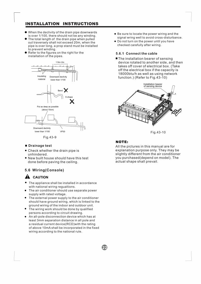
When the declivity of the drain pipe downwardsis over 1/100, there should not be any winding.The total length of the drain pipe when pulledout traversely shall not exceed 20m, when thepipe is over long, a prop stand must be installedto prevent winding.Refer to the figures on the right for theinstallation of the pipes.
1.5m~2m
Insulating
materialDownward declivity
lower than 1/100
Bend
S shape
VP30
Downward declivity
lower than 1/100
Put as deep as possible
(about 10cm)
Fig.43-9
Fig.43-10
Drainage test
Check whether the drain pipe isunhindered.New built house should have this testdone before paving the ceiling.
5.6 Wiring(Console)
CAUTION
The appliance shall be installed in accordance
with national wiring regualtions.
The air conditioner should use separate power
supply with rated voltage.
The external power supply to the air conditioner
should have ground wiring, which is linked to the
ground wiring of the indoor and outdoor unit.
The wiring work should be done by qualified
persons according to circuit drawing.
An all-pole disconnection device which has at
least 3mm separation distance in all pole and
a residual current device(RCD)with the rating
of above 10mA shall be incorporated in the fixed
wiring according to the national rule.
Be sure to locate the power wiring and the
signal wring well to avoid cross-disturbance.
Do not turn on the power until you have
checked carefully after wiring.
5.6.1 Connect the cable
The installation bearer of sensingdevice rotated to another side, and thentakes off cover of electrical box. (Takeoff the electrical box if the capacity is18000btu/h as well as using networkfunction.) (Refer to Fig.43-10)
Installation bearerof sensing device
All the pictures in this manual are forexplanation purpose only. They may beslightly different from the air conditioneryou purchased(depend on model). Theactual shape shall prevail.
NOTE:

23
Settlement of outdoor unit
Anchor the outdoor unit with
a bolt and nut 10 or 8 tightly
and horizontally on a concrete
or rigid mount.
φ φ
A
B
Air inlet
Air outlet
Air inlet
Fig.45
Install the outdoor unit on a rigid base toprevent increasing noise level and vibration.Determine the air outlet direction where thedischarged air is not blocked. In the case thatthe installation place is exposed to strong windsuch as a seaside, make sure the fan operatingproperly by putting the unit lengthwise along thewall or using a dust or shield plates.Specially in windy area, install the unit to prev-ent the admission of wind. If need suspendinginstallation, the installation bracket shouldaccord with technique requirement in theinstallation bracket diagram.The installation wall should be solid brick,concrete or the same intensity construction, oractions to reinforce, damping supporting shouldbe taken. The connection between bracket andwall, bracket and the air conditioner should befirm, stable and reliable.Be sure there is no obstacle which blockradiating air.
Strongwind
Fig.44
Outdoor unit installation
Outdoor installation precaution
INSTALLATION INSTRUCTIONS
Outdoor unit dimension
mm(WxHxD) A(mm)
530
560
B(mm)
290
335
623 366
590 333
Mounting dimensions
760x590x285
845x695x335
895x860x330
990x965x355

Fit the seal into the drain elbow, then insert the
drain joint into the base pan hole of outdoor unit,
rotate 90 to securely assemble them.
Connecting the drain joint with an extension drain
hose (Locally purchased), in case of the water
draining off the outdoor unit during the heating
mode.
。
Drain joint installation
Seal Drain joint Base pan hole ofoutdoor unit
Seal
Drain pipe
Refrigerant pipe connection
Oblique90。
Roughness BurrMain cause for refrigerant leakage
is due to defect in the flaring work.
Carry out correct flaring work
using the following procedure:
1. Use the piping kit accessory or pipes
purchased locally.
2. Measure the distance between the indoor
and the outdoor unit.
3. Cut the pipes a little longer than the
measured distance.
4. Cut the cable 1.5m longer than the pipe
length.
A: Cut the pipes and the cable.
1. Flaring work
Fig.46
B: Burr removal
1. Completely remove all burrs from the cutcross section of pipe/tube.
2. Put the end of the copper tube/pipe in adownward direction as you remove burrs inorder to avoid dropping burrs into the tubing.
Pipe
Reamer
Point down
Fig.47
Fig.48
C: Putting nut onRemove flare nuts attached to indoor andoutdoor unit, then put them on pipe/tubehaving completed burr removal.(not possibleto put them on after flaring work)
Flare nut
Copper tube
Fig.49
24
REFRIGERANT PIPE CONNECTION
25
ELECTRICAL WORK
Bar
Copper pipe
Clamp handleRed arrow mark
Cone
Yoke
Handle
Bar"A"
Fig.50
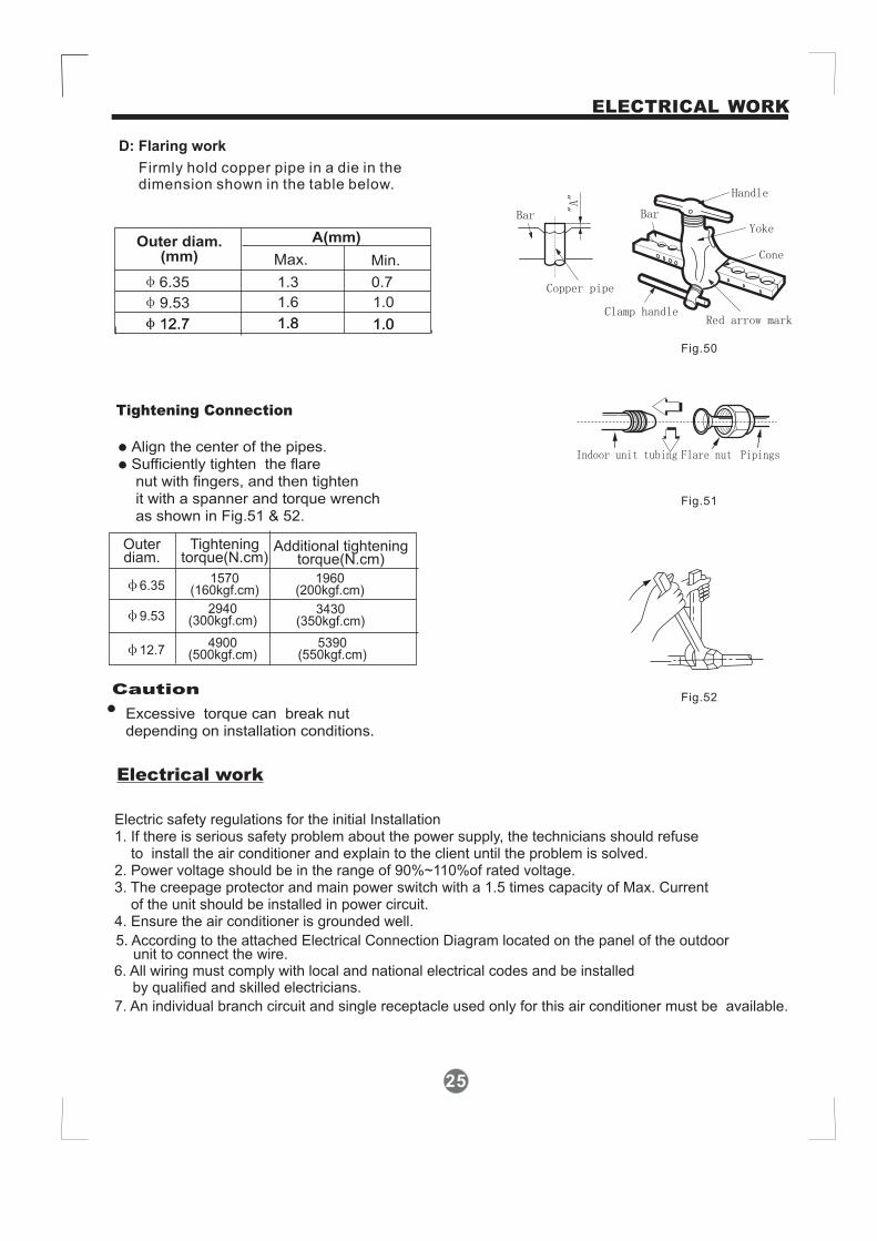
D: Flaring work
Firmly hold copper pipe in a die in thedimension shown in the table below.
Caution
Align the center of the pipes.Sufficiently tighten the flarenut with fingers, and then tightenit with a spanner and torque wrenchas shown in Fig.51 & 52.
Tightening Connection
Excessive torque can break nutdepending on installation conditions.
Outerdiam.
Tighteningtorque(N.cm)
Additional tighteningtorque(N.cm)
6.351570
(160kgf.cm)1960
(200kgf.cm)
4900(500kgf.cm)
5390(550kgf.cm)12.7
Outer diam.(mm)
A(mm)
Max. Min.
6.35 1.3 0.7
9.53 1.6 1.0
12.7 1.8 1.0
9.532940
(300kgf.cm)3430
(350kgf.cm)
Fig.52
Indoor unit tubing Flare nut Pipings
Fig.51
Electric safety regulations for the initial Installation1. If there is serious safety problem about the power supply, the technicians should refuse
to install the air conditioner and explain to the client until the problem is solved.2. Power voltage should be in the range of 90%~110%of rated voltage.3. The creepage protector and main power switch with a 1.5 times capacity of Max. Current
of the unit should be installed in power circuit.4. Ensure the air conditioner is grounded well.
7. An individual branch circuit and single receptacle used only for this air conditioner must be available.
5. According to the attached Electrical Connection Diagram located on the panel of the outdoorunit to connect the wire.
6. All wiring must comply with local and national electrical codes and be installedby qualified and skilled electricians.
12.7 1.8 1.0
Electrical work
26
ELECTRICAL WORK
Fig.53
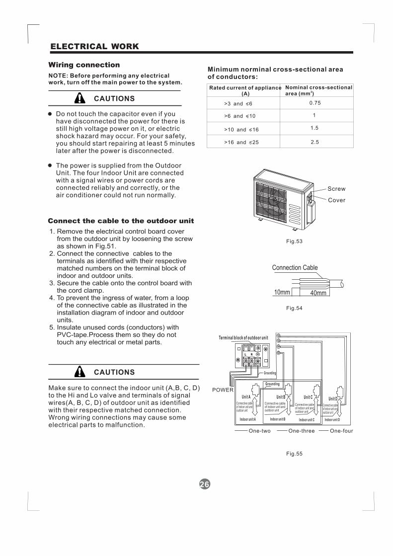
Connect the cable to the outdoor unit
1. Remove the electrical control board coverfrom the outdoor unit by loosening the screwas shown in Fig.51.
2. Connect the connective cables to theterminals as identified with their respectivematched numbers on the terminal block ofindoor and outdoor units.
3. Secure the cable onto the control board withthe cord clamp.
4. To prevent the ingress of water, from a loopof the connective cable as illustrated in theinstallation diagram of indoor and outdoorunits.
5. Insulate unused cords (conductors) withPVC-tape.Process them so they do nottouch any electrical or metal parts.
Wiring connection
NOTE: Before performing any electricalwork, turn off the main power to the system.
Connection Cable
10mm 40mm
Fig.55
CAUTIONS
Do not touch the capacitor even if youhave disconnected the power for there isstill high voltage power on it, or electricshock hazard may occur. For your safety,you should start repairing at least 5 minuteslater after the power is disconnected.
The power is supplied from the OutdoorUnit. The four Indoor Unit are connectedwith a signal wires or power cords areconnected reliably and correctly, or theair conditioner could not run normally.
Connective cableof indoor unit andoutdoor unit
Connective cableof indoor unit andoutdoor unit
Connective cableof indoor unit andoutdoor unit
Connective cableof indoor unit andoutdoor unit
One-two One-three One-four
Fig.54
CAUTIONS
Make sure to connect the indoor unit (A,B, C, D)to the Hi and Lo valve and terminals of signalwires(A, B, C, D) of outdoor unit as identifiedwith their respective matched connection.Wrong wiring connections may cause someelectrical parts to malfunction.
Minimum norminal cross-sectional areaof conductors:
Rated current of appliance(A)
Nominal cross-sectionalarea (mm )
2
>3 and <6
>6 and <10
>10 and <16
>16 and <25
0.75
1
1.5
2.5
POWER
Screw
Cover

NOTE:
For some models, the indoor unit is especially designed to used as either MULTI modelsor MONO models. If your air conditioner is not set to the MULTI position, see the followingINDOOR WIRING DIAGRAM to modify the indoor unit from MONO model to MULTI model.(Fig.56 & 57)1. Carefully remove the front panel and frame, then remove the Electricall control cover
by loosen the screw.2. Remove the POWER SUPPLY cord of MONO model(Fig.56).3. Unplug the then connect it
with“L” RED wire connected with “4” on pinboard of RY1,
“3” on pinboard of Ry1.4. Reinstall the Electrical Control cover and screw, rip off the white paper above the
Slide Switch and move it to the MULTI position(see Fig. 56).5. Reinstall the front panel and frame.6. Now the indoor unit can be used as MULTI models(Fig.57). Because the control
system is changed, the AUTO CLEAN function is unavailable for MULTI models.
INDOOR FAN MOTOR
LOUVER MOTOR
N
CN1 CN3CN6
CN7
CN8
CN2 CN17
CN9
5
7
L N S
L
Y/G
BLACK
RED
S
L
N
WHITERED
CN14CN11
OUTDOOR UNIT
INDOOR PCB
2
4S
YELLOW
TRANSFORMER
JX1
INDOOR WIRING DIAGRAMINDOOR WIRING DIAGRAM
ROOM TEMP. SENSOR
PIPE TEMP. SENSOR
CN4
AUTO RESTART
CN15
IONIZER
SWITCH BOARD DISPLAY BOARD
5
5CN12CN13
3
3
2
2
3
3
RY1
34
CN5
2
PLUMB STEP MOTORDOOR STEP MOTOR
2205209008
INDOOR FAN MOTOR
LOUVER MOTOR
N
CN1 CN3CN6
CN7
CN8
CN2 CN17
CN9
5
7
BROWN
BLUE
L N S
L
Y/G
BLACK
RED
S
L
N
WHITERED
CN14CN11
OUTDOOR UNIT
INDOOR PCB
POWER SUPPLY
2
4S
YELLOW
TRANSFORMER
JX1
Y/G
INDOOR WIRING DIAGRAMINDOOR WIRING DIAGRAM
ROOM TEMP. SENSOR
PIPE TEMP. SENSOR
CN4
AUTO RESTART
CN15
IONIZER
SWITCH BOARD DISPLAY BOARD
5
5CN12CN13
3
3
2
2
3
3
RY1
34
CN5
2
PLUMB STEP MOTORDOOR STEP MOTOR
MONO MODELS
MULTI MODELS
MONO
MONO
MULTI
Rip off thewhite paper
MONO
MONO
MULTI
Fig.56
Fig.57
ELECTRICAL WORK
27
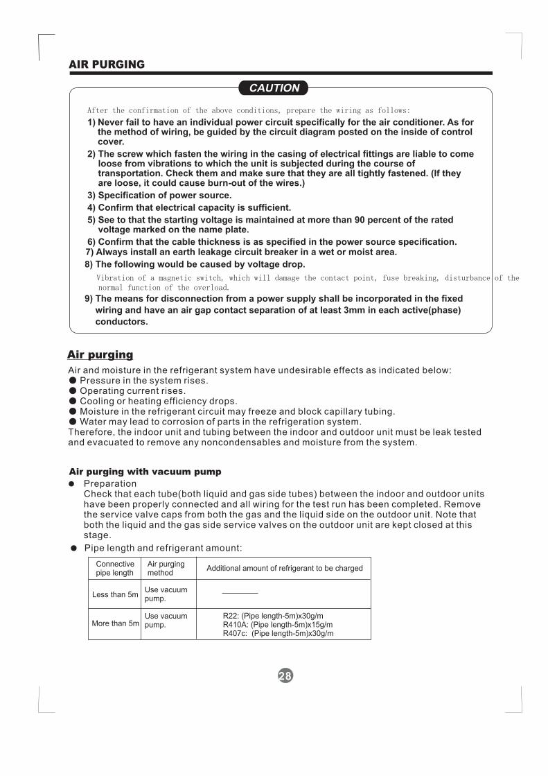
After the confirmation of the above conditions, prepare the wiring as follows:
1) Never fail to have an individual power circuit specifically for the air conditioner. As forthe method of wiring, be guided by the circuit diagram posted on the inside of controlcover.
2) The screw which fasten the wiring in the casing of electrical fittings are liable to comeloose from vibrations to which the unit is subjected during the course oftransportation. Check them and make sure that they are all tightly fastened. (If theyare loose, it could cause burn-out of the wires.)
3) Specification of power source.
4) Confirm that electrical capacity is sufficient.
5) See to that the starting voltage is maintained at more than 90 percent of the ratedvoltage marked on the name plate.
6) Confirm that the cable thickness is as specified in the power source specification.7) Always install an earth leakage circuit breaker in a wet or moist area.
8) The following would be caused by voltage drop.
Vibration of a magnetic switch, which will damage the contact point, fuse breaking, disturbance of thenormal function of the overload.
9) The means for disconnection from a power supply shall be incorporated in the fixed
wiring and have an air gap contact separation of at least 3mm in each active(phase)
conductors.
CAUTIONCAUTION CAUTIONCAUTION
Air and moisture in the refrigerant system have undesirable effects as indicated below:Pressure in the system rises.Operating current rises.Cooling or heating efficiency drops.Moisture in the refrigerant circuit may freeze and block capillary tubing.Water may lead to corrosion of parts in the refrigeration system.
Therefore, the indoor unit and tubing between the indoor and outdoor unit must be leak testedand evacuated to remove any noncondensables and moisture from the system.
●●●●●
Air purging with vacuum pump
● PreparationCheck that each tube(both liquid and gas side tubes) between the indoor and outdoor unitshave been properly connected and all wiring for the test run has been completed. Removethe service valve caps from both the gas and the liquid side on the outdoor unit. Note thatboth the liquid and the gas side service valves on the outdoor unit are kept closed at thisstage.
● Pipe length and refrigerant amount:
Connectivepipe length
Less than 5m
More than 5m
Air purgingmethod
Use vacuumpump.
Use vacuumpump.
Additional amount of refrigerant to be charged
AIR PURGING
Air purging
28
R22: (Pipe length-5m)x30g/mR410A: (Pipe length-5m)x15g/mR407c: (Pipe length-5m)x30g/m
29
AIR PURGING
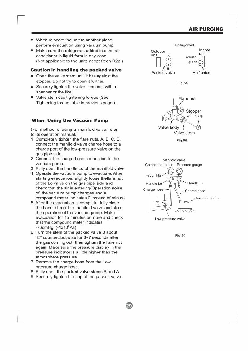
When relocate the unit to another place,
perform evacuation using vacuum pump.
Make sure the refrigerant added into the air
conditioner is liquid form in any case.
(Not applicable to the units adopt freon R22 )
Open the valve stem until it hits against the
stopper. Do not try to open it further.
Securely tighten the valve stem cap with a
spanner or the like.
Valve stem cap tightening torque (See
Tightening torque table in previous page ).
Outdoorunit
Indoorunit
Refrigerant
Flare nut
StopperCap
Valve body
Packed valve Half union
Gas side
Liquid side
A C
D
B
Valve stem
Fig.58
Fig.59
When Using the Vacuum Pump
(For method of using a manifold valve, referto its operation manual.)1. Completely tighten the flare nuts, A, B, C, D,
valve charge hose to acharge port of the low-pressure valve on thegas pipe side.
2. Connect the charge hose connection to thevacuum pump.
3. Fully open the handle Lo of the manifold valve.4. Operate the vacuum pump to evacuate. After
slightly loose theflare nutof the Lo valve on the gas pipe sidecheck that the air is entering(Operation noise
pump changes and acom meter indicates 0 instead of minus)
5. After the evacuation is complete, fully closemanifold valve and stop
the operation of the vacuum pump. Makeevacuation for 15 minutes or more
compound meter indicates
-76cmHg (-1x10 Pa).6. Turn the stem of the packed valve B about
45 counterclockwise for 6~7 seconds afterthe gas coming out, then tighten the flare nutagain. Make sure the pressure display in thepressure indicator is a little higher than theatmosphere pressure.
7. Remove the charge hose from the Lowpressure charge hose.
8. Fully open the packed valve stems B and A.9. Securely tighten the cap of the packed valve.
connect the manifold
starting evacuation,and
of the vacuumpound
the handle Lo of the
and checkthat the
5
o
Manifold valve
Compound meter
-76cmHg
Handle Lo Handle Hi
Charge hose Charge hose
Vacuum pump
Pressure gauge
Low pressure valve
Fig.60
Caution in handling the packed valve

Perform the electric safe check after
completing installation:
1. Insulated resistance
The insulated resistance must be more than
2M .
2. Grounding work
After finishing grounding work, measure the
grounding resistance by visual detection and
grounding resistance tester. Make sure the
grounding resistance is less than 4 .
3. Electrical leakage check (performing during
test running)
During test operation after finishing installation,
the serviceman can use the electroprobe and
multimeter to perform the electrical leakage
check. Turn off the unit immediately if leakage
happens. Check and find out the solution
ways till the unit operate properly.
Ω
Ω
A: Lo packed valve B: Hi packed valve
C and D are ends of indoor unit connection.
CAUTION
Electrical safety check●
Gas leak check●
1.Apply a soap water or a liquid neutraldetergent on the indoor unit connectionor outdoor unit connections by a softbrush to check for leakage of theconnecting points of th piping. If bubblescome out, the pipes have leakage.
2.
Soap water method:
Leak detectorUse the leak detector to check for leakage.
Safety and leakage check
15
Indoor unitcheck point
Outdoor unitcheck point
n m k j i h
A
B
C
a
c
b
d
e
f
a,b,c,d,h,i,j , k are points for one-two type.a,b,c,d,e,f,,h,i,j,k,m,n are points for one-three type.
Indoor unitcheck point
Outdoor unitcheck point
One-four type
30
AIR PURGING
Fig.61
Fig.62NOTE: The illustration is for explanationpurpose only. The actual order of A, B, Cand D on the machine may be slightlydifferent from the unit you purchased. Theactual shape shall prevail.

Test running
Perform test operation after completing gas leak check at the flare nut connections andelectrical safety check.
Check that all tubing and wiring have been properly connected.Check that the gas and liquid side service valves are fully open.
1. Connect the power, press the ON/OFF button on the remote controller to turn the unit on.2. Use the MODE button to select COOL, HEAT, AUTO and FAN to check if all the functions
works well.3. When the amient temperature is too low(lower than 17 C), the unit cannot be controlled by
the remote controller to run at cooling mode, manual operation can be taken. Manualoperation is used only when the remote controller is disable or maintenance necessary.
Press the Manual control button to select the AUTO or COOL, the unit will operate underForced AUTO or COOL mode(see User Manual for details).
4. The test operation should last about 30 minutes.
Hold the panel sides and lift the panel up to an angle until it remains fixed with a clickingsound.
Manual control
Button
31
TEST RUNNING
Fig.63
Manual controlbutton AUTO/COOL

CS464-I202000191053
090703