Embed Size (px)
Citation preview
Instruction ManualInverter Control Pump
ISO 9001 Certified
Walrus America Inc
Congratulations on your purchase of Walrus IC Series Inverter Control System. Please read all
instructions carefully before installing your new system. The system has been designed and
manufactured to give trouble free, reliable operation. Upon receiving, please check the
following:
a. No shipping damage.
b. Product specs match name plate data (such as pressure, voltage, HP, etc).
1. Functions and Featuresa. The system provides constant pressure despite varying consumption.
b. Pump will automatically shut off when it is in dry run.
c. The pump will compensate the pressure loss due to the leak in the system.
d. Available for Simplex and Duplex.
e. Pump will start when the tap is open and shut off when the water flow is stopped .
2. Installation 2.1 Installation site
a. Choose a site dry and with good ventilation. The ambient temperature is at 36°F-104°F.
b. Recommend to install inside. If you have to install outside, please provide a pump house with
water proof and frost free to protect from weather
c. No vibration and unusual electrical surge.
d. Easy access for maintenance.
2.2 Cautions of installation
a. Avoid sucking in any solid particles; especially bounding glue or chips from pipe work.
b. Make sure the power supply is correctly connected at 1-phase 230V, 3-phase 230V or 3-phase
460V.
c. Never run pump dry; and keep the pumped liquid below 104°F. Make sure your system is
always connected to an adequate, reliable source of clean water.
d. For your safety, be sure the GFCI (Ground Fault Circuit Interrupter) is in your system and
grounding is properly connected to prevent from electric shock.
When using a regular GFCI (Ground Fault Circuit Interrupter), please select a current
sensor with sensitivity of 200mA, and not less than 0.1-second detection time to avoid
nuisance tripping. When using a designated GFCI for AC motor drive, please select a current
sensor with sensitivity of 30mA or above.
~ 1 ~

3. Control Panel
a. 1~5HP: The system status is displayed on Inverter Digital Keypad.
• 1Ø 230V (1~3HP) • 3Ø 230V • 3Ø 460V
3.0:0.0RUN ▲ MODE
STOP
STOPRUNFWDREV
RESET ▼ ENTER
Set pressure in kgf/cm² Actual operating pressure in kgf/cm²
MODE
▲
▼
~ 2 ~
Function of the Digital Keypad:
Press to increase the pressure
Press each time to display the different data (i.e pressure, frequency and current, etc.)
The system allows user to change the pressure only.
Press to reduce the pressure
Refer to psi conversion in the section of “ pressure adjustment ”
RUN
STOPRESET
ENTER
~ 3 ~
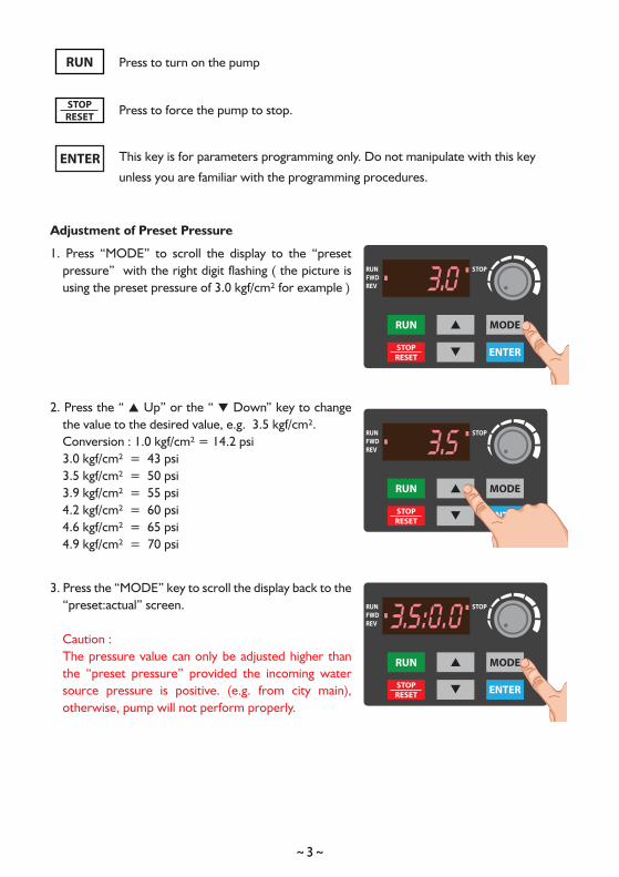
Press to turn on the pump
Press to force the pump to stop.
Adjustment of Preset Pressure
1. Press “MODE” to scroll the display to the “preset pressure” with the right digit flashing ( the picture is using the preset pressure of 3.0 kgf/cm² for example )
2. Press the “ ▲ Up” or the “ ▼ Down” key to change the value to the desired value, e.g. 3.5 kgf/cm².Conversion : 1.0 kgf/cm² = 14.2 psi3.0 kgf/cm² = 43 psi3.5 kgf/cm² = 50 psi3.9 kgf/cm² = 55 psi4.2 kgf/cm² = 60 psi4.6 kgf/cm² = 65 psi4.9 kgf/cm² = 70 psi
3. Press the “MODE” key to scroll the display back to the “preset:actual” screen.
Caution : The pressure value can only be adjusted higher than the “preset pressure” provided the incoming water source pressure is positive. (e.g. from city main), otherwise, pump will not perform properly.
3.0RUN ▲ MODE
STOP
STOPRUNFWDREV
RESET ▼ ENTER
3.5RUN ▲ MODE
STOP
STOPRUNFWDREV
RESET ▼ ENTER
3.5:0.0RUN ▲ MODE
STOP
STOPRUNFWDREV
RESET ▼ ENTER
This key is for parameters programming only. Do not manipulate with this key
unless you are familiar with the programming procedures.
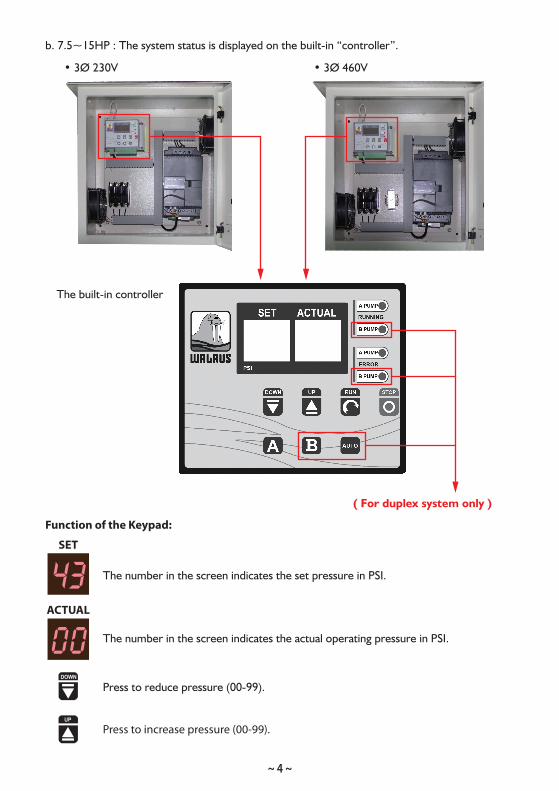
b. 7.5~15HP : The system status is displayed on the built-in “controller”.
• 3Ø 230V • 3Ø 460V
UP
DOWN
~ 4 ~
The built-in controller
( For duplex system only )
Function of the Keypad:
SET
43ACTUAL
00
The number in the screen indicates the set pressure in PSI.
The number in the screen indicates the actual operating pressure in PSI.
Press to reduce pressure (00-99).
Press to increase pressure (00-99).

DOWN
STOP
RUN
Adjustment of Preset Pressure
1. When you start up the pump, the SET pressure indicates the factory default pressure. It is also
the max. constant pressure the pump will work. It can be set lower by pressing until the
SET screen shows the number you desire, and then press to memorize the new setting.
2. You can not increase the SET pressure unless you have positive incoming pressure from your
water source. For example, you have 10 psi incoming pressure and the default pressure is 50 psi,
you can adjust the SET pressure up to 60 psi as max. Make sure your positive incoming pressure
is very stable because the pump performance will be affected once your incoming pressure is
fluctuated.
3. To increase SET pressure, please press to the number you desire, and then press to
memorize the new setting.
4. For other adjustment, please contact us for more information.
Remarks:
. After finishing any adjustment of the above, please be sure to press to default the new
setting. If you do not press , the pump will resume the previous setting when the power
turns off.
. When the indicator display “ ”, the pump is in dry run and it will be shut off automatically.
The default is set to stop for 10 minutes and the pump will attempt to run 2 minutes and stop
for 10 minutes. The stop-and-run cycle will be continued until the water supply is normal. It is
highly recommended to shut off the pump when the water supply has problem as continue to
run the pump dry will cause serious damage.
STOP
STOPUP
~ 5 ~
Press to force the pump to stop. Under normal operation, the pump will stop
automatically when the tap is closed.
It is also the function memory key.
Press to turn on the pump
STOP
STOP
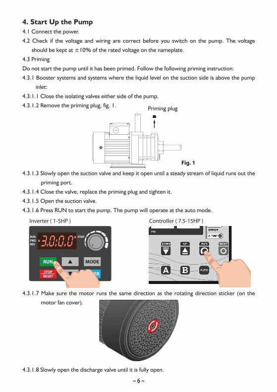
4. Start Up the Pump4.1 Connect the power.
4.2 Check if the voltage and wiring are correct before you switch on the pump. The voltage
should be kept at ±10% of the rated voltage on the nameplate.
4.3 Priming
Do not start the pump until it has been primed. Follow the following priming instruction:
4.3.1 Booster systems and systems where the liquid level on the suction side is above the pump
inlet:
4.3.1.1 Close the isolating valves either side of the pump.
4.3.1.2 Remove the priming plug, fig. 1.
4.3.1.3 Slowly open the suction valve and keep it open until a steady stream of liquid runs out the
priming port.
4.3.1.4 Close the valve, replace the priming plug and tighten it.
4.3.1.5 Open the suction valve.
4.3.1.6 Press RUN to start the pump. The pump will operate at the auto mode.
4.3.1.7 Make sure the motor runs the same direction as the rotating direction sticker (on the
motor fan cover).
4.3.1.8 Slowly open the discharge valve until it is fully open.
Fig. 1
Priming plug
3.0:0.0RUN ▲ MODE
STOP
STOPRUNFWDREV
RESET ▼ ENTER
~ 6 ~
Inverter ( 1-5HP ) Controller ( 7.5-15HP )
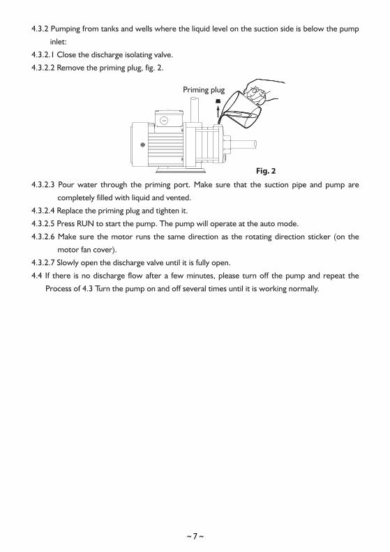
4.3.2 Pumping from tanks and wells where the liquid level on the suction side is below the pump
inlet:
4.3.2.1 Close the discharge isolating valve.
4.3.2.2 Remove the priming plug, fig. 2.
4.3.2.3 Pour water through the priming port. Make sure that the suction pipe and pump are
completely filled with liquid and vented.
4.3.2.4 Replace the priming plug and tighten it.
4.3.2.5 Press RUN to start the pump. The pump will operate at the auto mode.
4.3.2.6 Make sure the motor runs the same direction as the rotating direction sticker (on the
motor fan cover).
4.3.2.7 Slowly open the discharge valve until it is fully open.
4.4 If there is no discharge flow after a few minutes, please turn off the pump and repeat the
Process of 4.3 Turn the pump on and off several times until it is working normally.
Fig. 2
Priming plug
~ 7 ~
~ 8 ~
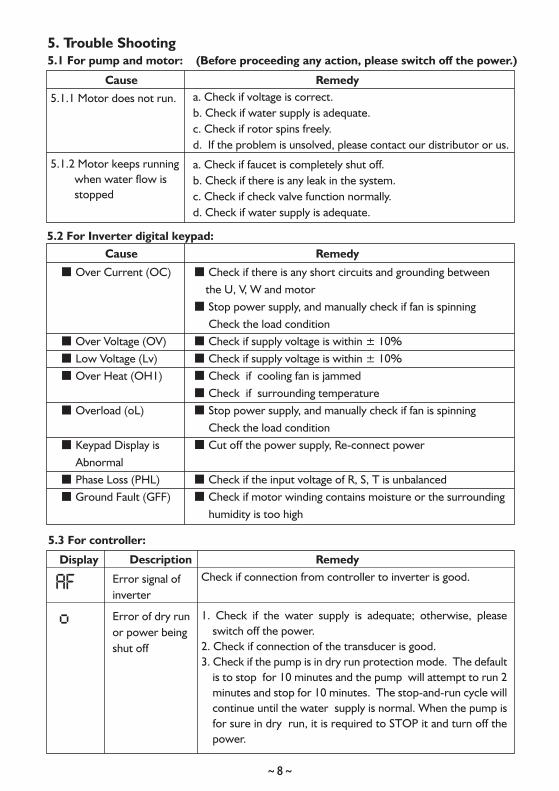
5. Trouble Shooting5.1 For pump and motor: (Before proceeding any action, please switch off the power.)
5.2 For Inverter digital keypad:
RemedyCause
RemedyCause
5.1.2 Motor keeps running when water flow is stopped
5.1.1 Motor does not run. a. Check if voltage is correct.b. Check if water supply is adequate.c. Check if rotor spins freely.d. If the problem is unsolved, please contact our distributor or us.
a. Check if faucet is completely shut off.b. Check if there is any leak in the system.c. Check if check valve function normally.d. Check if water supply is adequate.
■ Over Current (OC)
■ Over Voltage (OV) ■ Low Voltage (Lv) ■ Over Heat (OH1)
■ Overload (oL)
■ Keypad Display is Abnormal■ Phase Loss (PHL)■ Ground Fault (GFF)
■ Check if there is any short circuits and grounding between the U, V, W and motor■ Stop power supply, and manually check if fan is spinning Check the load condition■ Check if supply voltage is within ± 10%■ Check if supply voltage is within ± 10%■ Check if cooling fan is jammed■ Check if surrounding temperature■ Stop power supply, and manually check if fan is spinning Check the load condition■ Cut off the power supply, Re-connect power
■ Check if the input voltage of R, S, T is unbalanced■ Check if motor winding contains moisture or the surrounding humidity is too high
Error of dry runor power being shut off
Display Description Remedy
5.3 For controller:
Check if connection from controller to inverter is good.Error signal ofinverter
1. Check if the water supply is adequate; otherwise, please switch off the power.
2. Check if connection of the transducer is good.3. Check if the pump is in dry run protection mode. The default
is to stop for 10 minutes and the pump will attempt to run 2 minutes and stop for 10 minutes. The stop-and-run cycle will continue until the water supply is normal. When the pump is for sure in dry run, it is required to STOP it and turn off the power.
~ 9 ~
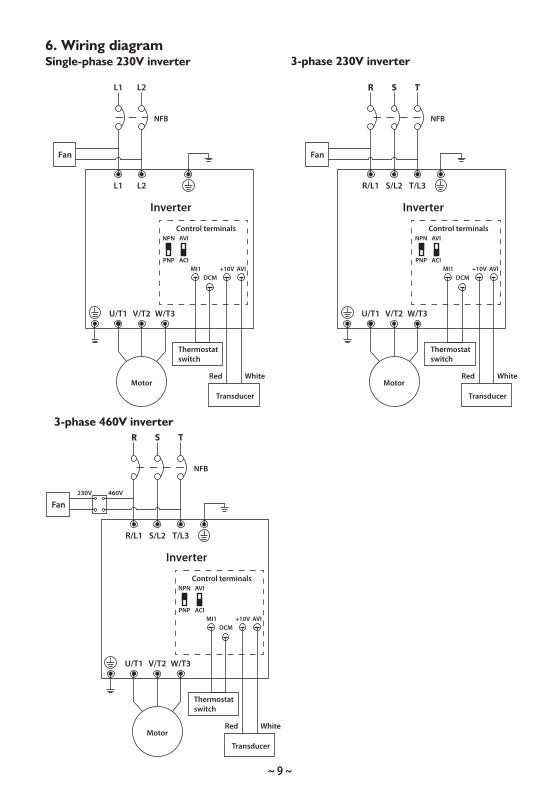
6. Wiring diagramSingle-phase 230V inverter
Thermostat switch
Thermostat switch
Thermostat switch
U/T1 V/T2 W/T3
R S T
NFB
R/L1 S/L2 T/L3
Motor
Inverter
Transducer
DCM+10V AVIMI1
AVI
ACI
WhiteRed
Control terminals
Fan460V230V
NPN
PNP
3-phase 460V inverter
U/T1 V/T2 W/T3
R S T
NFB
R/L1 S/L2 T/L3
Motor
Inverter
Transducer
DCM+10V AVIMI1
AVI
ACI
WhiteRed
Control terminals
Fan
NPN
PNP
U/T1 V/T2 W/T3
L1 L2
NFB
L1 L2
Motor
Inverter
Transducer
DCM+10V AVIMI1
AVI
ACI
WhiteRed
Control terminals
Fan
NPN
PNP
3-phase 230V inverter
~ 10 ~
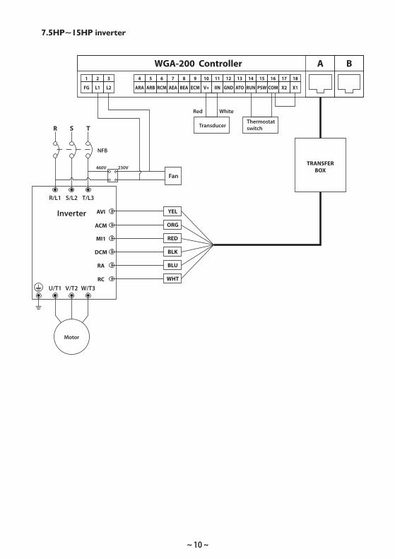
7.5HP~15HP inverter
Thermostat switch
U/T1 V/T2 W/T3
R S T
NFB
R/L1 S/L2 T/L3
Motor
Inverter
Transducer
AVI
WhiteRed
Fan460V 230V
1
FG
4
ARA
5
ARB
6
RCM
7
AEA
8
BEA
9
ECM
10
V+
11
IIN
12
GND
13
ATO
14
RUN
15
PSW
16
COM
17
X2
18
X1
3
L2
2
L1
AWGA-200 Controller B
YEL
ORG
RED
BLK
BLU
WHT
ACM
MI1
DCM
RA
RC
TRANSFERBOX
~ 11 ~
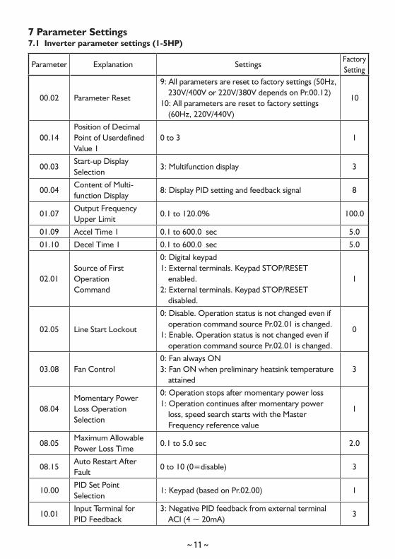
7 Parameter Settings7.1 Inverter parameter settings (1-5HP)
Parameter Explanation SettingsFactorySetting
00.02 Parameter Reset
9: All parameters are reset to factory settings (50Hz, 230V/400V or 220V/380V depends on Pr.00.12)
10: All parameters are reset to factory settings (60Hz, 220V/440V)
10
00.14Position of DecimalPoint of UserdefinedValue 1
0 to 3 1
00.03Start-up DisplaySelection
3: Multifunction display 3
00.04Content of Multi-function Display
8: Display PID setting and feedback signal 8
01.07Output FrequencyUpper Limit
0.1 to 120.0% 100.0
01.09 Accel Time 1 0.1 to 600.0 sec 5.0
01.10 Decel Time 1 0.1 to 600.0 sec 5.0
02.01Source of FirstOperationCommand
0: Digital keypad1: External terminals. Keypad STOP/RESET
enabled.2: External terminals. Keypad STOP/RESET
disabled.
1
02.05 Line Start Lockout
0: Disable. Operation status is not changed even if operation command source Pr.02.01 is changed.
1: Enable. Operation status is not changed even if operation command source Pr.02.01 is changed.
0
03.08 Fan Control0: Fan always ON3: Fan ON when preliminary heatsink temperature
attained3
08.04Momentary PowerLoss OperationSelection
0: Operation stops after momentary power loss1: Operation continues after momentary power
loss, speed search starts with the Master Frequency reference value
1
08.05Maximum AllowablePower Loss Time
0.1 to 5.0 sec 2.0
08.15Auto Restart AfterFault
0 to 10 (0=disable) 3
10.00PID Set PointSelection
1: Keypad (based on Pr.02.00) 1
10.01Input Terminal forPID Feedback
3: Negative PID feedback from external terminal ACI (4 ~ 20mA)
3
~ 12 ~
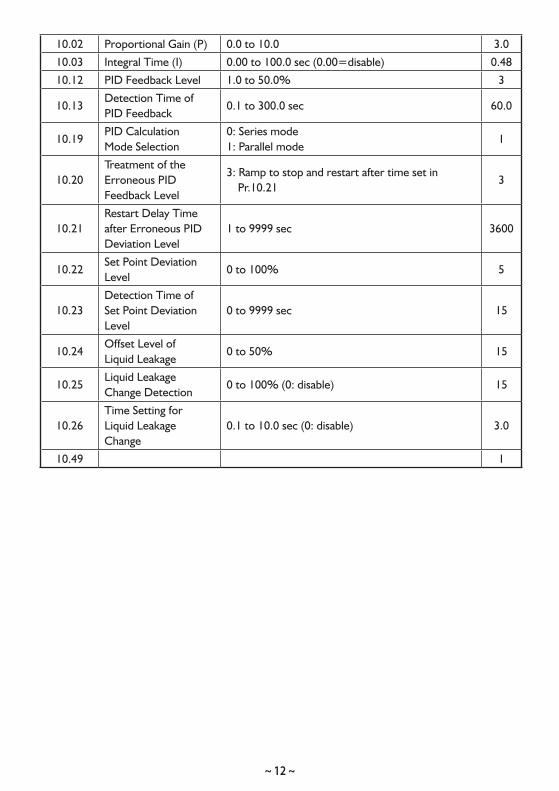
10.02 Proportional Gain (P) 0.0 to 10.0 3.0
10.03 Integral Time (I) 0.00 to 100.0 sec (0.00=disable) 0.48
10.12 PID Feedback Level 1.0 to 50.0% 3
10.13Detection Time ofPID Feedback
0.1 to 300.0 sec 60.0
10.19PID CalculationMode Selection
0: Series mode1: Parallel mode
1
10.20Treatment of theErroneous PIDFeedback Level
3: Ramp to stop and restart after time set in Pr.10.21
3
10.21Restart Delay Timeafter Erroneous PIDDeviation Level
1 to 9999 sec 3600
10.22Set Point DeviationLevel
0 to 100% 5
10.23Detection Time ofSet Point DeviationLevel
0 to 9999 sec 15
10.24Offset Level ofLiquid Leakage
0 to 50% 15
10.25Liquid LeakageChange Detection
0 to 100% (0: disable) 15
10.26Time Setting forLiquid LeakageChange
0.1 to 10.0 sec (0: disable) 3.0
10.49 1
~ 13 ~
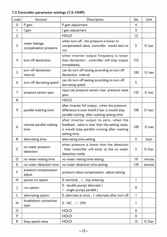
7.2 Controller parameter settings (7.5-15HP)
code function Description Set Unit
0 P gain P gain adjustment 4
1 I gain I gain adjustment 3
2 HOLD 12
3water leakage compensation pressure
when turn off , the pressure is lower to compensated value, controller would start to run
5 0.1psi
4 turn off dectectionwhen inverter output frequency is lower than dectection , controller will stop output immediately.
153
5turn off dectection interval
can do turn off testing according to turn off dectection interval
100 0.1sec
6 turn off decresing speedcan do turn off testing according to turn off decresing speed
5
7 pressure sensor specinput use pressure sensor max. pressure vaule spec.
142 0.1psi
8 HOLD -
9 parallel waitting timeafter inverter full output , when the pressure difference is over than0.2 bar, it would stop parallel running after waitting setting time
100 0.1sec
Aremote parallel watting time
after inverter output to zero, when the feedback value is over than the setting vaule, it would stop parallel running after watting setting time
100 0.1sec
B alternating time alternating time setting 5 hour
Cno water pressure detection
when pressure is lower than the detection , then contorller will enter to the no water detection mode
5 0.1bar
D no water resting time no water resting time setting 10 minute
E no water detection time no water detection time setting 120 second
Fpressure compensation adjust
pressure value compensation adjust setting
H power on option 0: terminal , 1 : key entering 1
J run option0 : double pump( alternate ) 1 : single pump( parallel )
0
L alternating option 0: alternate at once , 1: alternate after turn off 1
Nbreakdown connection type
0 : NC , 1 : ON 1
O HOLD 0
P HOLD 0
R Stop speed value HOLD 15 0.1bar
~ 14 ~
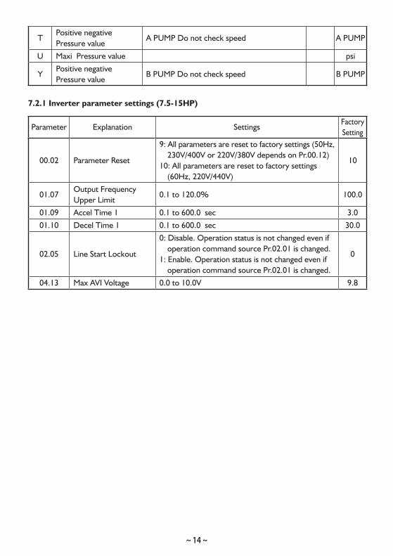
TPositive negative Pressure value
A PUMP Do not check speed A PUMP
U Maxi Pressure value psi
YPositive negative Pressure value
B PUMP Do not check speed B PUMP
7.2.1 Inverter parameter settings (7.5-15HP)
Parameter Explanation SettingsFactorySetting
00.02 Parameter Reset
9: All parameters are reset to factory settings (50Hz, 230V/400V or 220V/380V depends on Pr.00.12)
10: All parameters are reset to factory settings (60Hz, 220V/440V)
10
01.07Output FrequencyUpper Limit
0.1 to 120.0% 100.0
01.09 Accel Time 1 0.1 to 600.0 sec 3.0
01.10 Decel Time 1 0.1 to 600.0 sec 30.0
02.05 Line Start Lockout
0: Disable. Operation status is not changed even if operation command source Pr.02.01 is changed.
1: Enable. Operation status is not changed even if operation command source Pr.02.01 is changed.
0
04.13 Max AVI Voltage 0.0 to 10.0V 9.8

Limited WarrantyProducts manufactured by Walrus Pumps Co (Walrus) are warranted to the first user only to be free of defects in material and workmanship for a period of 12 months from date of installation, but no more than 24 months from date of shipment. Walrus' liability under this warranty shall be limited to repairing or replacing at our election, without charge, FOB Walrus' distribution center or authorized service agent. Walrus will not be liable for any cost of removal, installation, transportation or any other charges that may arise in connection with warranty claim.
The warranty period commences on the date of original purchase of the equipment. Proof of purchase and installation date, failure date, and supporting installation data must be provided when claiming repairs under warranty.
This warranty is subject to due compliance by the original purchaser with all directions and conditions set out in the installation and operating instructions. Failure to comply with these instructions, damage or breakdown caused by fair wear and tear, negligence, misuse, incorrect installation, inappropriate chemicals or additives in the water, inadequate protection against freezing, rain or other adverse weather conditions, corrosive or abrasive water, lightning or high voltage spikes or through unauthorized persons attempting repairs are not covered under warranty.
Walrus will not be liable for any incidental or consequential damages, losses, or expenses, arising from installation, use, or any other causes. There are no express or implied warranties, including merchantability or fitness for a particular purpose, which extend beyond those warranties described or referred to above.
Certain states do not permit the exclusion or limitation of incidental or consequential damages or the placing of limitations on the duration of an implied warranty, therefore, the limitations or exclusions herein may not apply. This warranty sets forth specific legal rights and obligations, however, additional rights may exist, which may vary from state to state.
Supersedes all previous publications
CC
70D
0008
D02
0UW
0R00
Walrus America Inc20220 Hempstead Road, Suite #30, Houston, TX 77065
Web: www.walrusamerica.com