Embed Size (px)
Citation preview
Unitary DC Inverter System
Unitary DC Inverter System
Part 1 General Information
Part 2 Indoor Units
Part 3 Outdoor Units
Part 4 Installation of Outdoor Units
Part 5 Control System
Part 1 General Information
Part 1 General Information
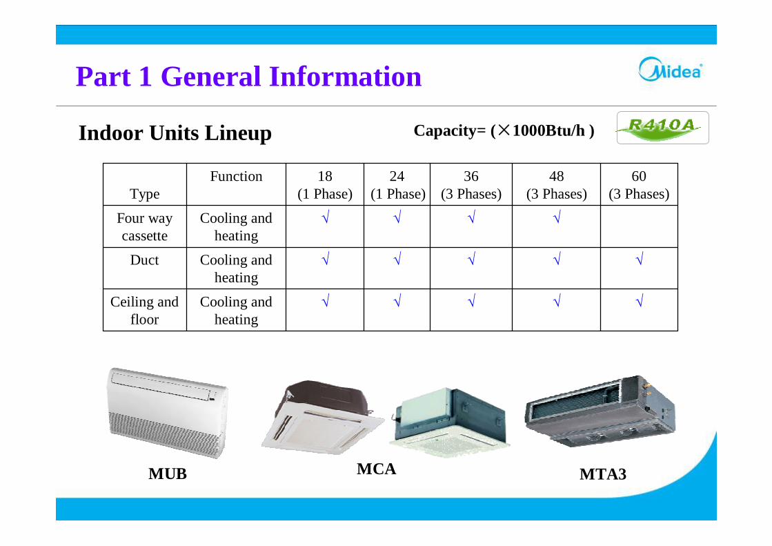
Indoor Units Lineup
√√√√√Cooling and heating
Ceiling and floor
√√√√√Cooling and heating
Duct
√√√√Cooling and heating
Four way cassette
60(3 Phases)
48(3 Phases)
36(3 Phases)
24(1 Phase)
18(1 Phase)
FunctionType
Capacity= (×1000Btu/h )
MUB MCA MTA3
Part 1 General Information
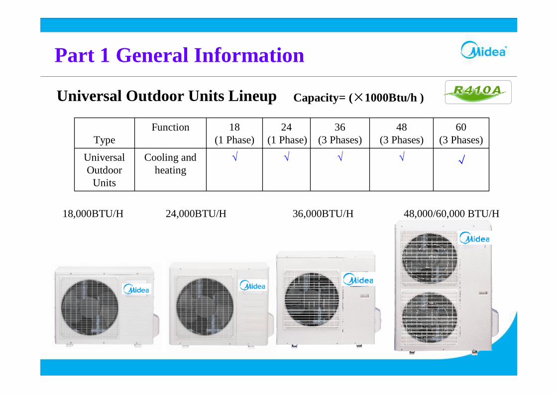
Universal Outdoor Units Lineup
√√√√√Cooling and heating
UniversalOutdoor
Units
60(3 Phases)
48(3 Phases)
36(3 Phases)
24(1 Phase)
18(1 Phase)
FunctionType
Capacity= (×1000Btu/h )
18,000BTU/H 24,000BTU/H 36,000BTU/H 48,000/60,000 BTU/H
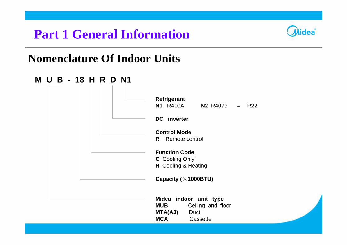
Nomenclature Of Indoor Units
Part 1 General Information
RefrigerantN1 R410A N2 R407c -- R22
DC inverter
Control ModeR Remote control
Function CodeC Cooling OnlyH Cooling & Heating
Capacity (×1000BTU)
Midea indoor unit typeMUB Ceiling and floorMTA(A3) DuctMCA Cassette
M U B - 18 H R D N1
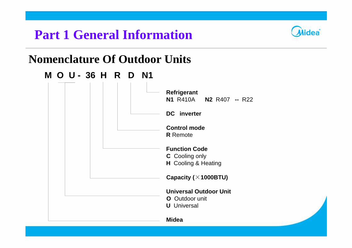
Nomenclature Of Outdoor Units
Part 1 General Information
M O U - 36 H R D N1
RefrigerantN1 R410A N2 R407 -- R22
DC inverter
Control modeR Remote
Function CodeC Cooling onlyH Cooling & Heating
Capacity (×1000BTU)
Universal Outdoor UnitO Outdoor unit U Universal
Midea
Part 2 Indoor Units
Part 2 Indoor Units
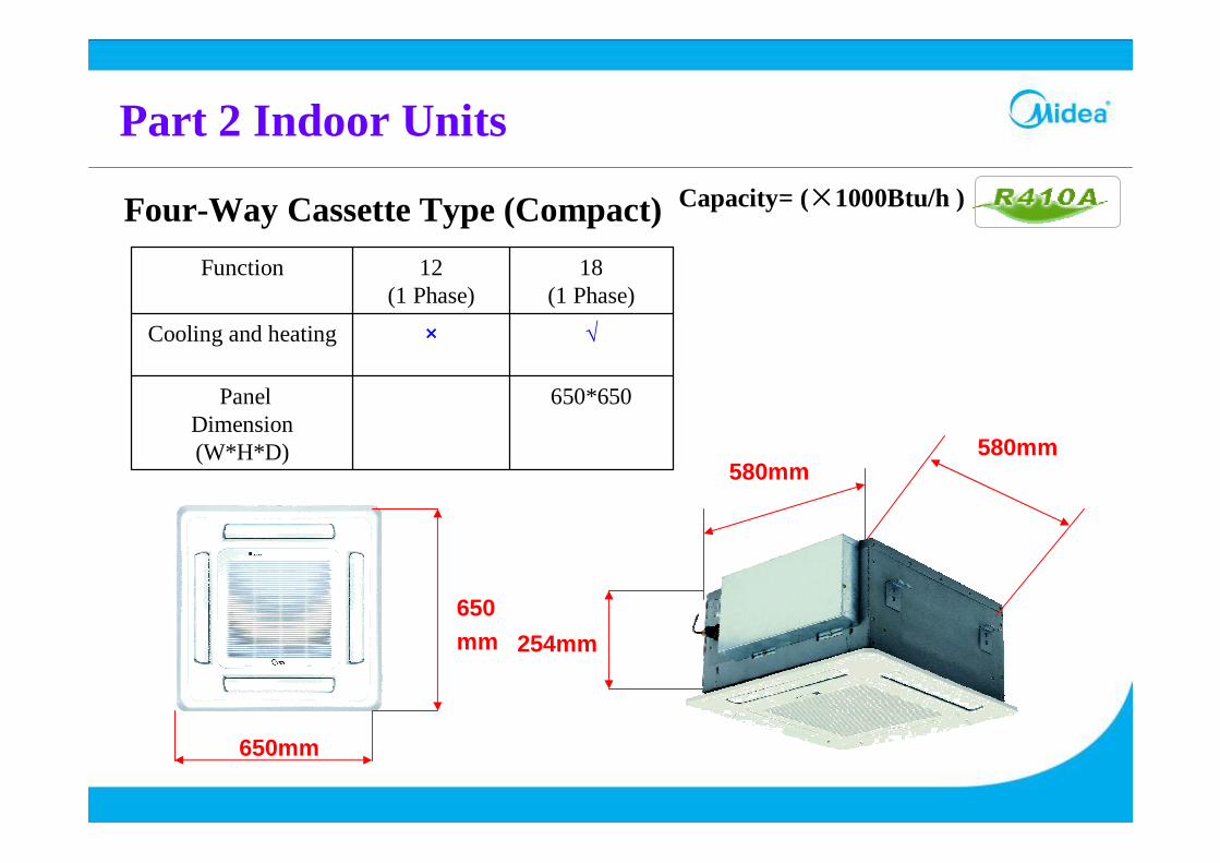
Four-Way Cassette Type (Compact)
650*650PanelDimension(W*H*D)
√×Cooling and heating
18(1 Phase)
12(1 Phase)
Function
Capacity= (×1000Btu/h )
254mm
580mm580mm
650mm
650mm
Part 2 Indoor Units
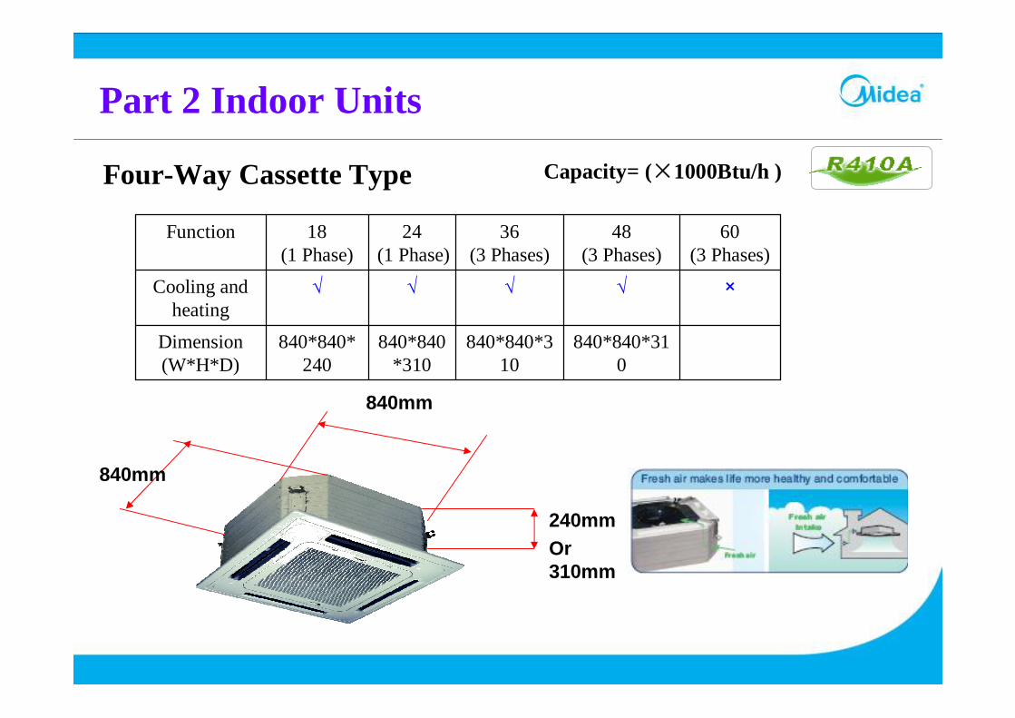
Four-Way Cassette Type
840*840*310
840*840*310
840*840*310
840*840*240
Dimension(W*H*D)
×√√√√Cooling and heating
60(3 Phases)
48(3 Phases)
36(3 Phases)
24(1 Phase)
18(1 Phase)
Function
Capacity= (×1000Btu/h )
840mm
240mmOr 310mm
840mm
Part 2 Indoor Units
1670*680*240
1670*680*240
1285*660*198
995*660*198
995*660*198
Dimension(W*H*D)
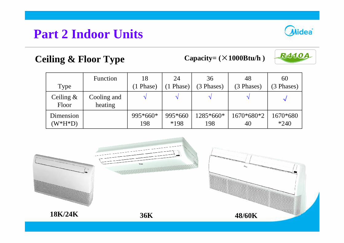
√√√√√Cooling and heating
Ceiling & Floor
60(3 Phases)
48(3 Phases)
36(3 Phases)
24(1 Phase)
18(1 Phase)
FunctionType
Capacity= (×1000Btu/h )Ceiling & Floor Type
18K/24K 36K 48/60K
Part 2 Indoor Units
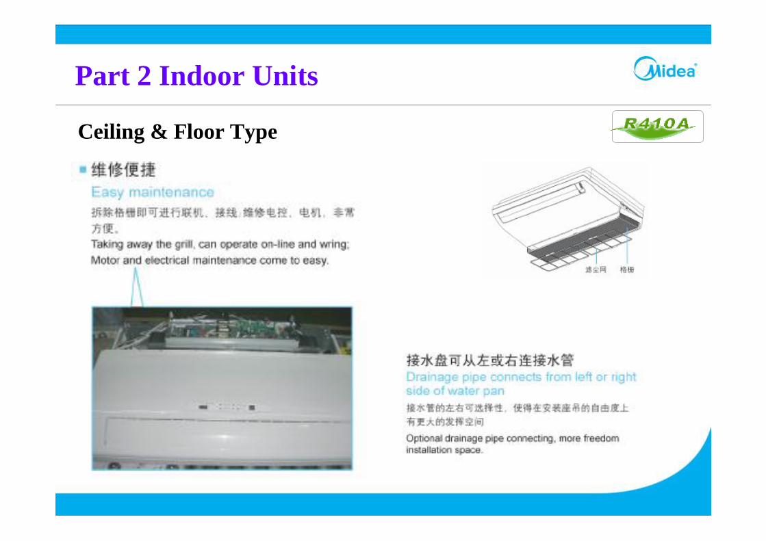
Ceiling & Floor Type
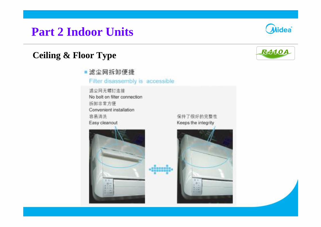
Part 2 Indoor Units
Ceiling & Floor Type
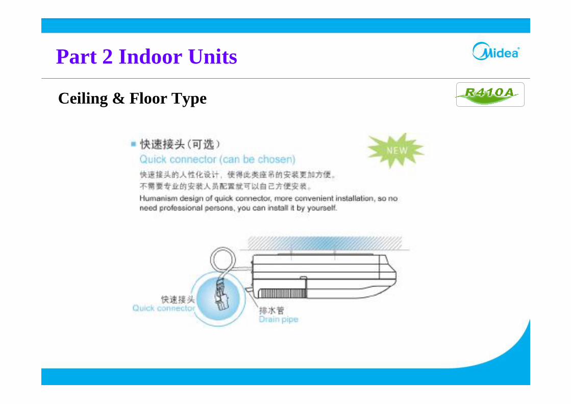
Part 2 Indoor Units
Ceiling & Floor Type

Part 2 Indoor Units
1350*800*320
1350*800*320
1350*800*298
1000*800*298
1000*800*298
Dimension(W*H*D)
96 Pa70 Pa70 Pa40 Pa40 PaStatic Pressure(Hi)
√√√√√Cooling and heating
Ceiling & Floor
60(3 Phases)
48(3 Phases)
36(3 Phases)
24(1
Phase)
18(1 Phase)
FunctionType
Duct Type
1000mm
800mm
298mm800mm
1350mm
320mm
MTA3MTA
Part 2 Indoor Units
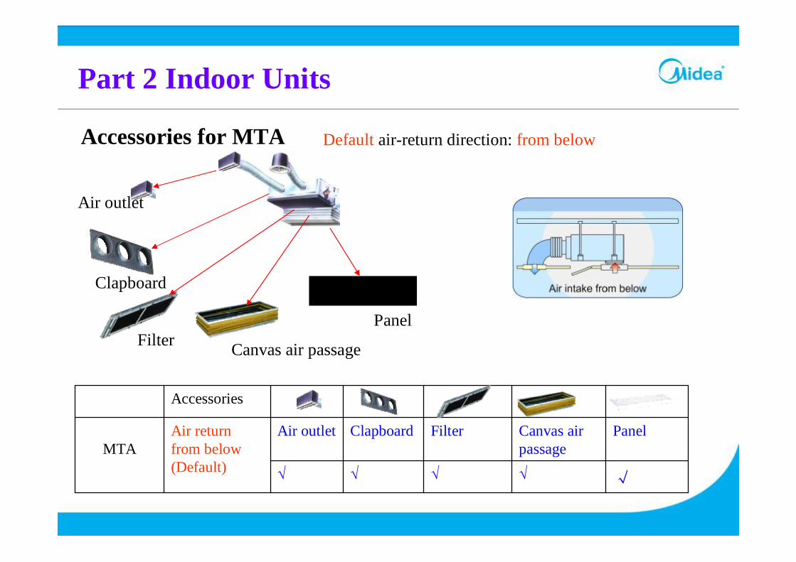
Accessories for MTA Default air-return direction: from below
Air outlet
Clapboard
Filter Canvas air passage
Panel
√√√√√
PanelCanvas air passage
FilterClapboardAir outletAir return from below(Default)
MTA
Accessories
Part 2 Indoor Units
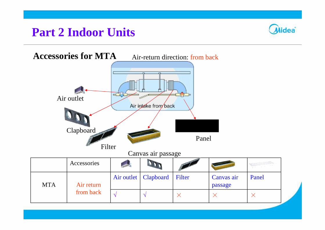
Accessories for MTA Air-return direction: from back
×××√√
PanelCanvas air passage
FilterClapboardAir outletAir return from back
MTA
Accessories
Air outlet
Clapboard
FilterCanvas air passage
Panel

Part 2 Indoor Units
Accessories for MTA3 Default air-return direction: from back
××√√√
PanelCanvas air passage
FilterClapboardAir outletAir return from back(Default)
MTA3
Accessories
Air outlet
Clapboard
FilterPanel
Part 2 Indoor Units
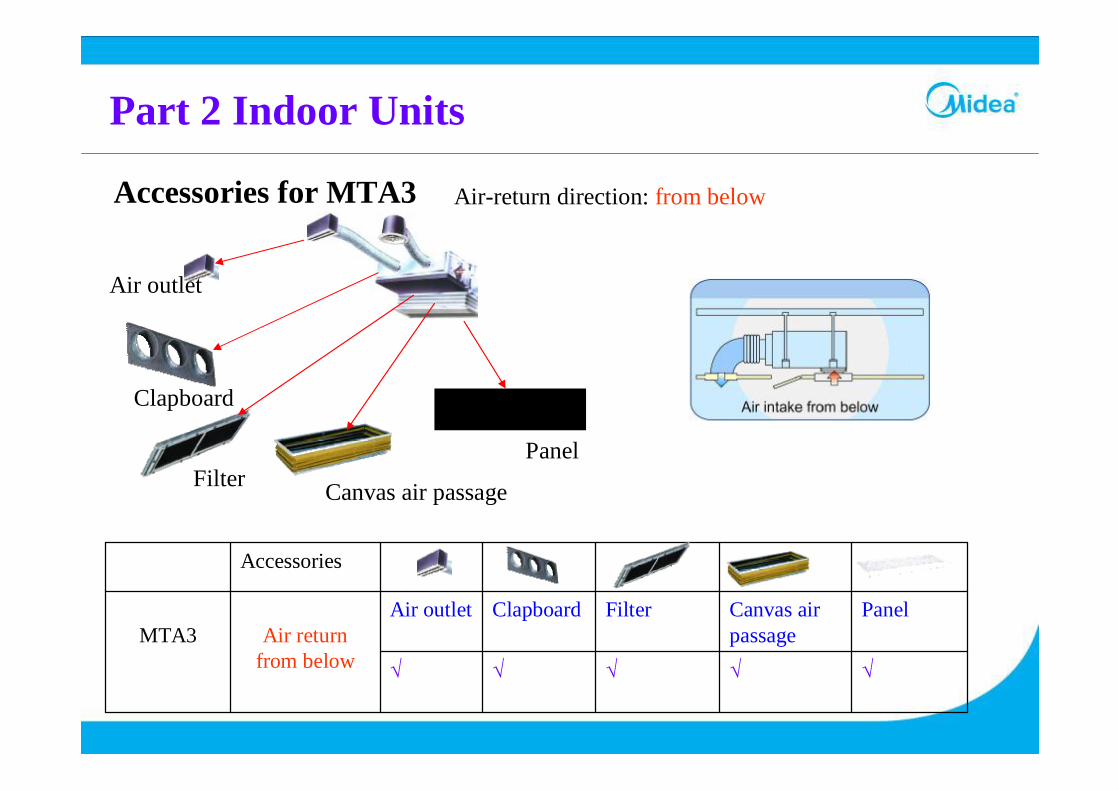
Accessories for MTA3 Air-return direction: from below
√√√√√
PanelCanvas air passage
FilterClapboardAir outletAir return
from belowMTA3
Accessories
Air outlet
Clapboard
Filter Canvas air passage
Panel
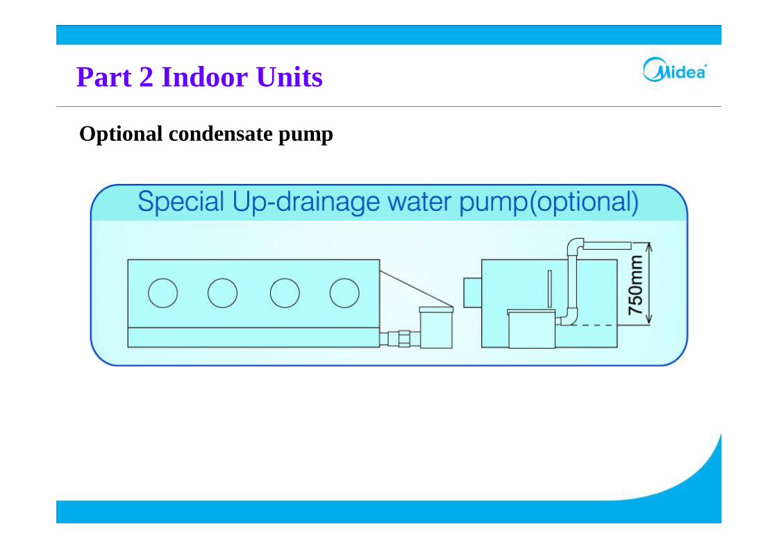
Part 2 Indoor Units
Optional condensate pump

Optional condensate pump
Part 2 Indoor Units
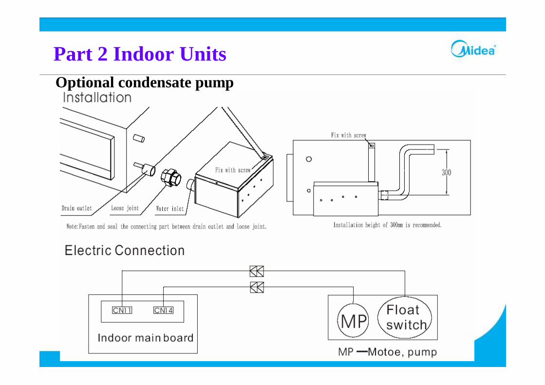
Optional condensate pump
Part 2 Indoor Units
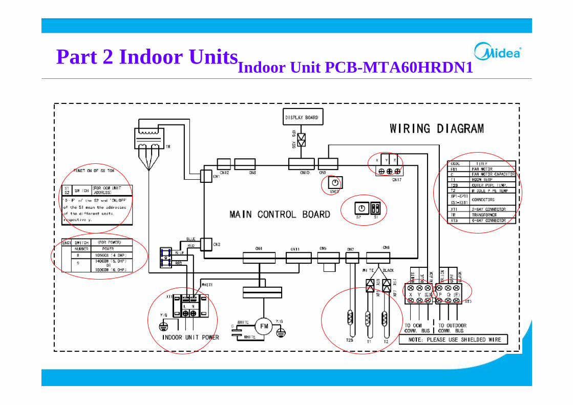
Part 2 Indoor UnitsIndoor Unit PCB-MTA60HRDN1
Part 3 Outdoor Units
Part 3 Outdoor Units
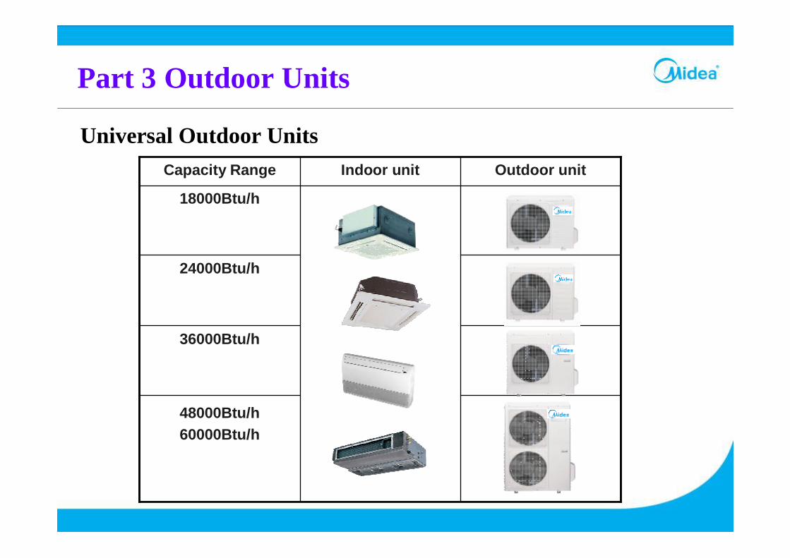
48000Btu/h60000Btu/h
36000Btu/h
24000Btu/h
18000Btu/h
Outdoor unitIndoor unitCapacity Range
Universal Outdoor Units
Part 3 Outdoor Units
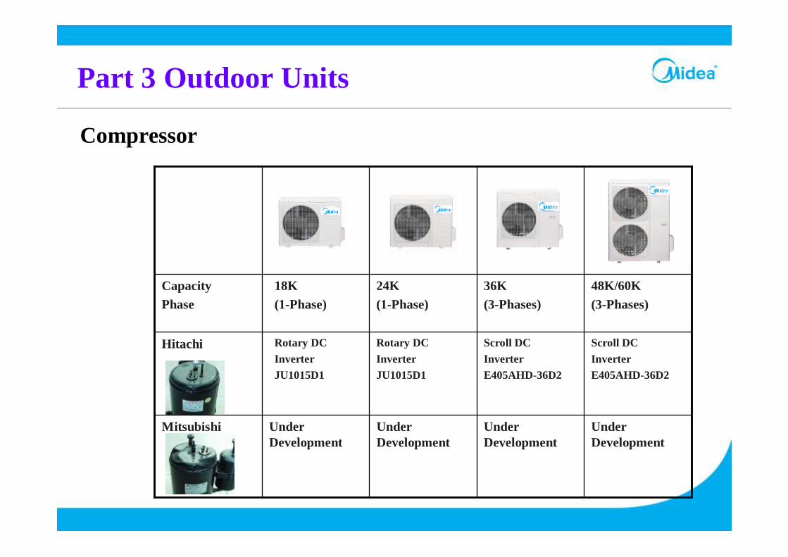
Under Development
Mitsubishi
Rotary DCInverterJU1015D1
Hitachi
48K/60K(3-Phases)
36K(3-Phases)
24K(1-Phase)
18K(1-Phase)
CapacityPhase
Compressor
Rotary DCInverterJU1015D1
Scroll DCInverterE405AHD-36D2
Scroll DCInverterE405AHD-36D2
Under Development
Under Development
Under Development
Part 3 Outdoor Units
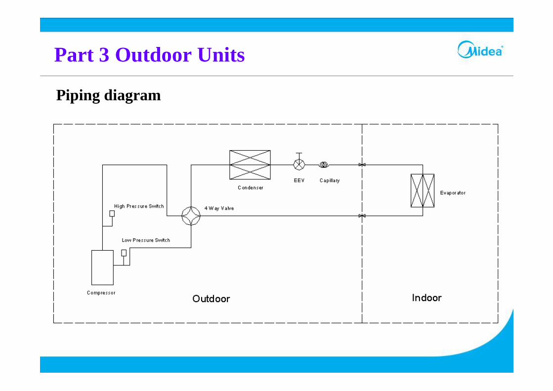
Piping diagram
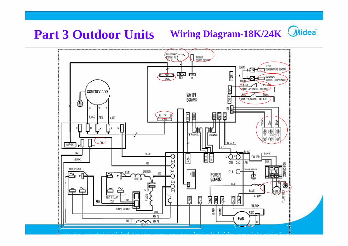
Part 3 Outdoor Units Wiring Diagram-18K/24K
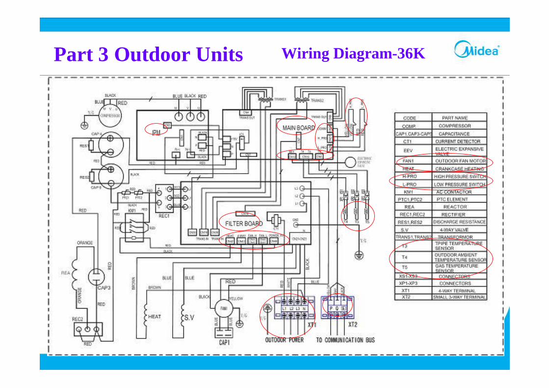
Part 3 Outdoor Units Wiring Diagram-36K
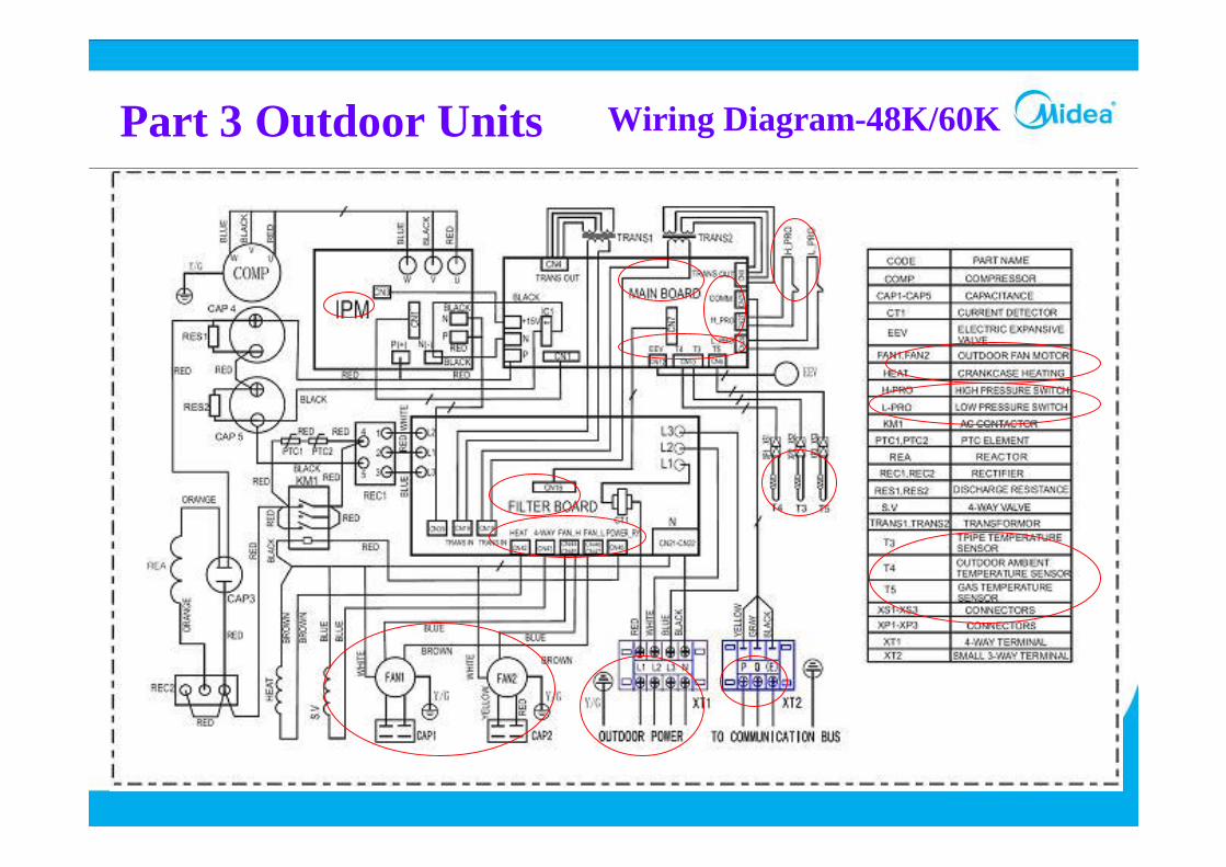
Part 3 Outdoor Units Wiring Diagram-48K/60K
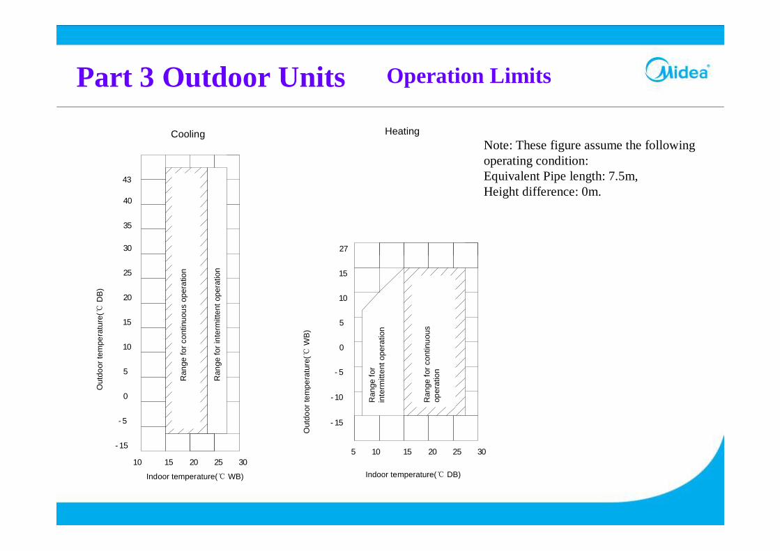
Part 3 Outdoor Units Operation Limits
43
Indoor temperature(℃ DB)
Out
door
tem
pera
ture
(℃ W
B)
HeatingCooling
40
35
30
25
20
15
10
5
0
-5
-15
10 15 20 25 30
3025201510
-15
-10
-5
0
5
10
15
27
Out
door
tem
pera
ture
(℃ D
B)
Indoor temperature(℃ WB)
5
Ran
ge fo
r con
tinuo
us
oper
atio
n
Ran
ge fo
r con
tinuo
us o
pera
tion
Ran
ge fo
r int
erm
itten
t ope
ratio
n
Ran
ge fo
r in
term
itten
t ope
ratio
n
Note: These figure assume the following operating condition: Equivalent Pipe length: 7.5m,Height difference: 0m.
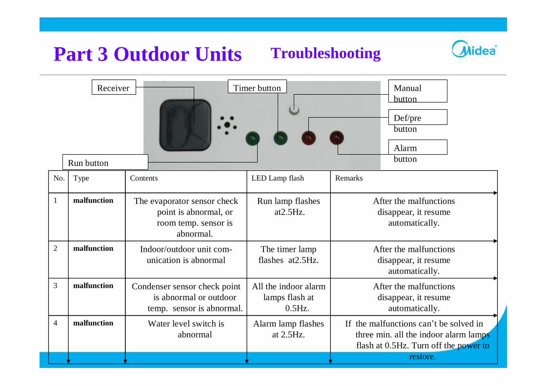
Part 3 Outdoor Units Troubleshooting
Manual button
Def/pre button
Alarm button
Receiver
Run button
Timer button
If the malfunctions can’t be solved in three min. all the indoor alarm lamps flash at 0.5Hz. Turn off the power to
restore.
Alarm lamp flashesat 2.5Hz.
Water level switch is abnormal
malfunction4
After the malfunctionsdisappear, it resume
automatically.
All the indoor alarmlamps flash at
0.5Hz.
Condenser sensor check point is abnormal or outdoor
temp. sensor is abnormal.
malfunction3
After the malfunctionsdisappear, it resume
automatically.
The timer lamp flashes at2.5Hz.
Indoor/outdoor unit com-unication is abnormal
malfunction2
After the malfunctionsdisappear, it resume
automatically.
Run lamp flashesat2.5Hz.
The evaporator sensor check point is abnormal, or room temp. sensor is
abnormal.
malfunction1
RemarksLED Lamp flashContentsTypeNo.
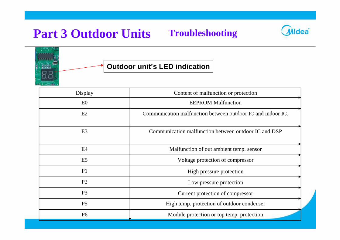
Part 3 Outdoor Units Troubleshooting
Module protection or top temp. protectionP6
High temp. protection of outdoor condenserP5
Current protection of compressorP3
Low pressure protectionP2
High pressure protectionP1
Voltage protection of compressorE5
Malfunction of out ambient temp. sensorE4
Communication malfunction between outdoor IC and DSPE3
Communication malfunction between outdoor IC and indoor IC.E2
EEPROM MalfunctionE0
Content of malfunction or protectionDisplay
Outdoor unit’s LED indication
Part 4 Installation Of Outdoor Units
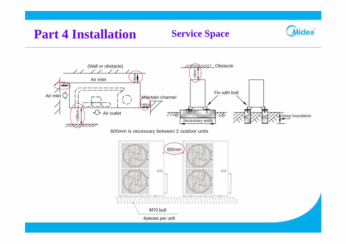
Part 4 Installation Service Space
>30cm
>60cm
>30c
m
>20
0cm
(Wall or obstacle)
Air inlet
Air outlet
Air inlet
Maintain channel
>60c
m
Obstacle
Fix with bolt
Deep foundation Necessary width
600mm is necessary between 2 outdoor units
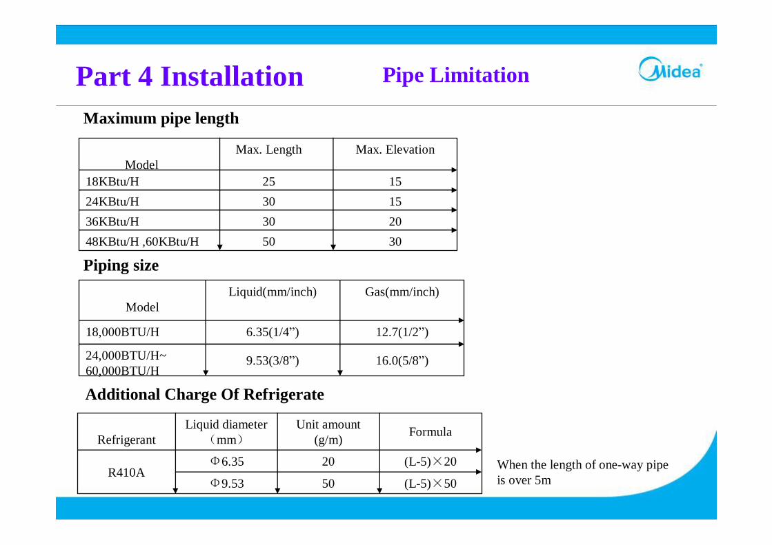
Part 4 Installation Pipe Limitation
Maximum pipe length
305048KBtu/H ,60KBtu/H203036KBtu/H153024KBtu/H152518KBtu/H
Max. ElevationMax. LengthModel
Piping size
16.0(5/8”)9.53(3/8”)24,000BTU/H~ 60,000BTU/H
12.7(1/2”)6.35(1/4”)18,000BTU/H
Gas(mm/inch)Liquid(mm/inch)Model
Additional Charge Of Refrigerate
When the length of one-way pipe is over 5m(L-5)×5050Φ9.53
(L-5)×2020Φ6.35R410A
FormulaUnit amount (g/m)
Liquid diameter(mm)Refrigerant
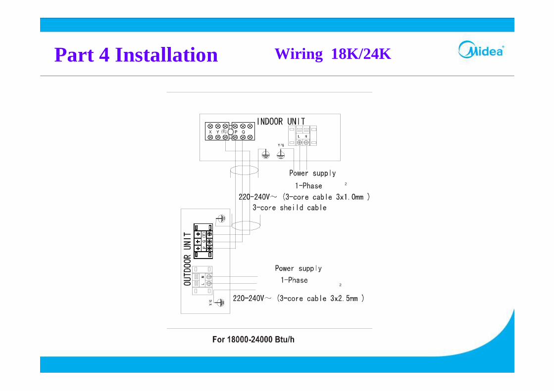
Part 4 Installation Wiring 18K/24K
2
2
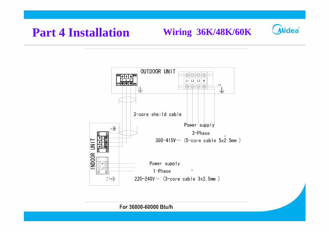
Part 4 Installation Wiring 36K/48K/60K
2
2
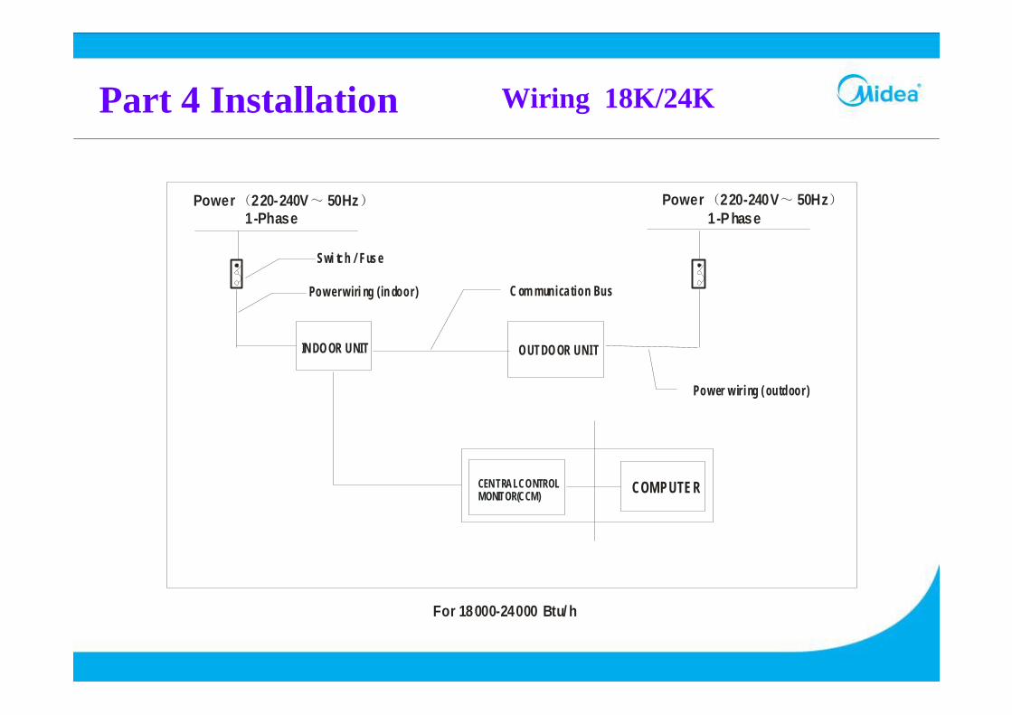
Part 4 Installation Wiring 18K/24K
CEN TRAL CONTROL MONITOR(CCM)
OUTDO OR UNI T
COM PUTER
IN DO OR UNIT
Power 220-240V 50Hz( ~ )
Swi tch / Fuse
Pow er wiri ng (in door ) C om munica tion Bus
Power 220-240V 50Hz( ~ )
Power w ir i ng ( outdoor )
1-P hase1-Phase
For 18000-24000 Btu/ h
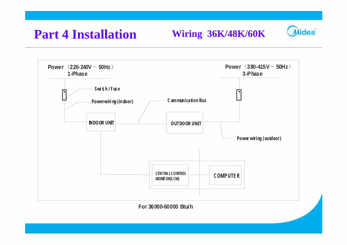
Part 4 Installation Wiring 36K/48K/60K
CEN TRA L CONTROL MONITOR(CCM)
OUTDOOR UNIT
COM P UTER
IN DOOR UNIT
Power 220-240V 50Hz( ~ )
Swi tch / Fuse
Power wiri ng (in door) C om munica tion Bus
Power 380-415V 50Hz( ~ )
Power wir ing ( outdoor)
3-Phase1-Phase
For 36000-60000 Btu/ h

Part 5 Control System
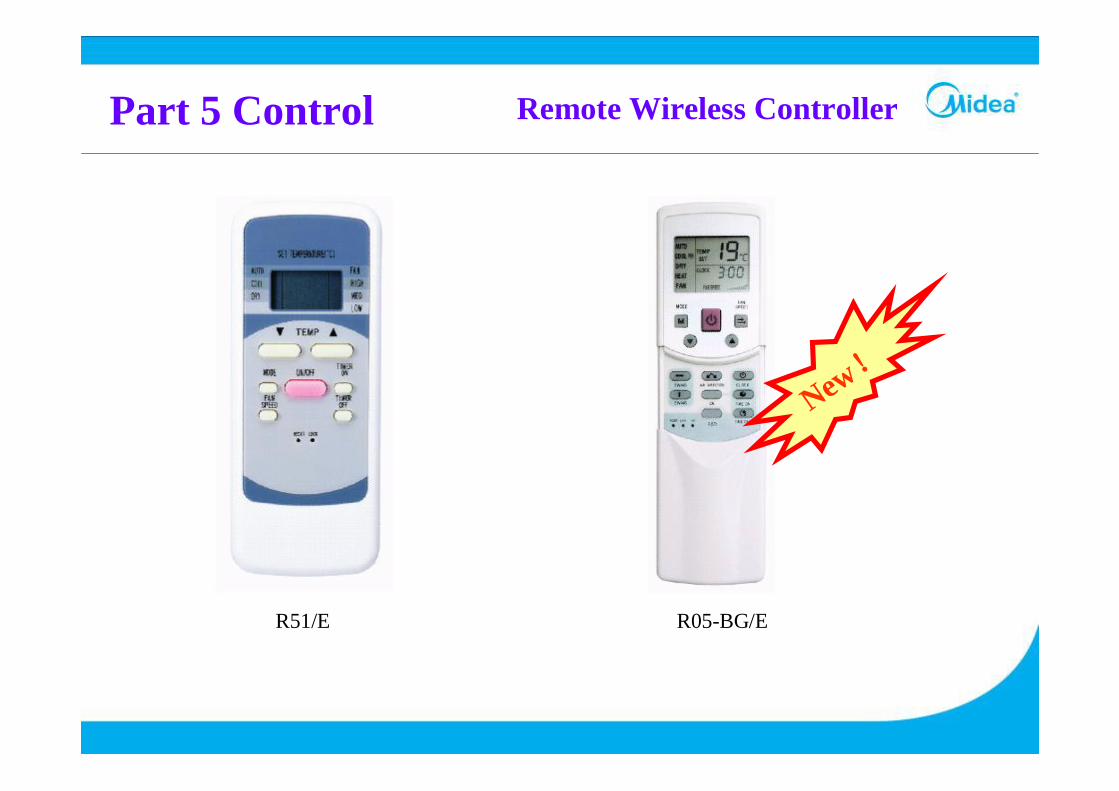
Part 5 Control Remote Wireless Controller
R51/E R05-BG/E
New!

Part 5 Control Remote Wire Controller
KJR-01/E
Customers can adjust it according to the model and their requirement . It is necessary to re-electrify after adjustment.
1 ON2 ON
1 ON2 OFF
1 OFF2 ON
1 OFF2 OFF
Mid-speed Fancooling&heating
Mid-speed Fancooling only
No mid-speed Fancooling&heating
No mid-speed Fancooling only
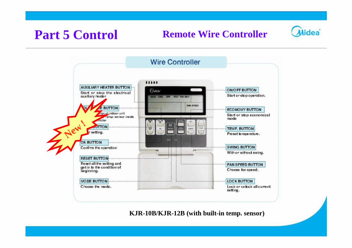
Part 5 Control Remote Wire Controller
KJR-10B/KJR-12B (with built-in temp. sensor)
New!
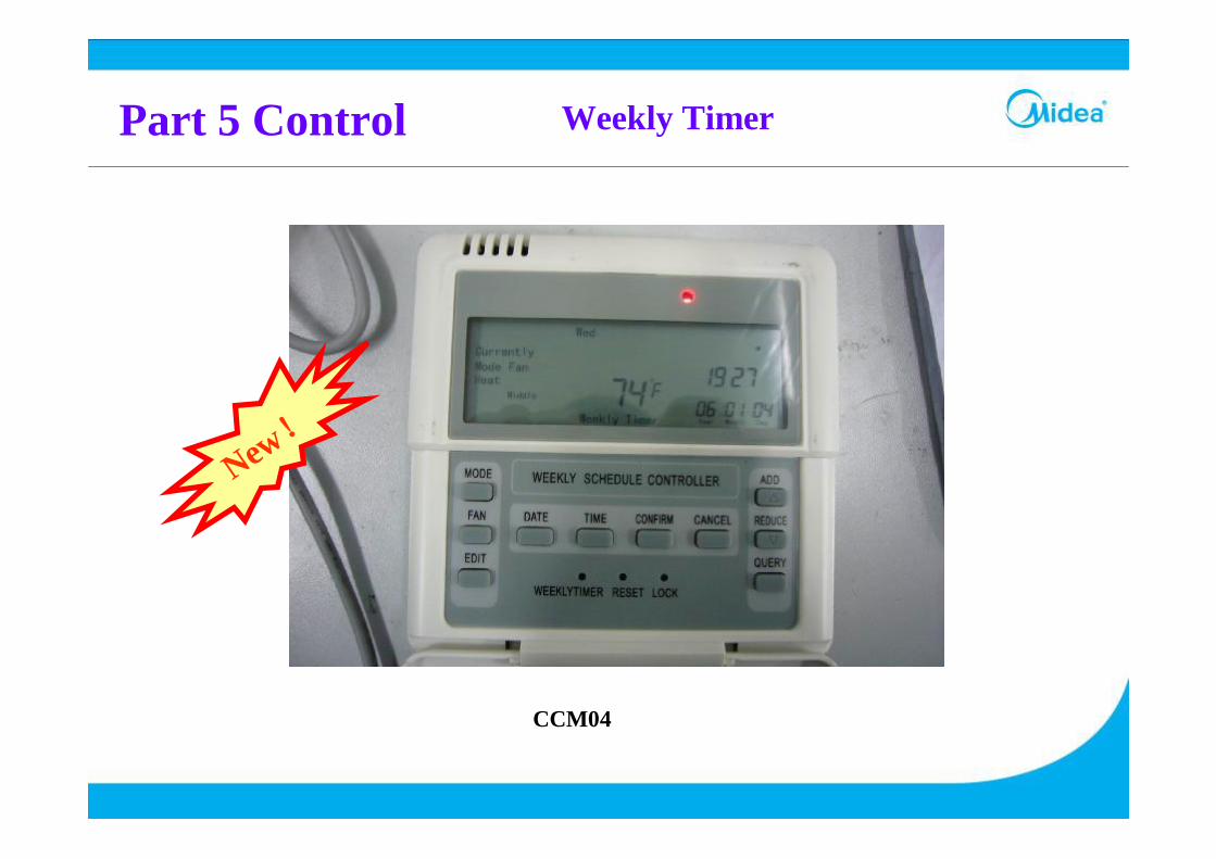
Part 5 Control Weekly Timer
CCM04
New!

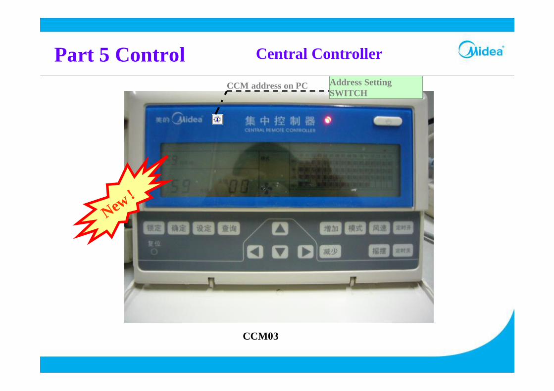
Part 5 Control Central Controller
CCM01
Address Setting SWITCHCCM address on PC
Part 5 Control Central Controller
CCM03
New!
Address Setting SWITCH
CCM address on PC
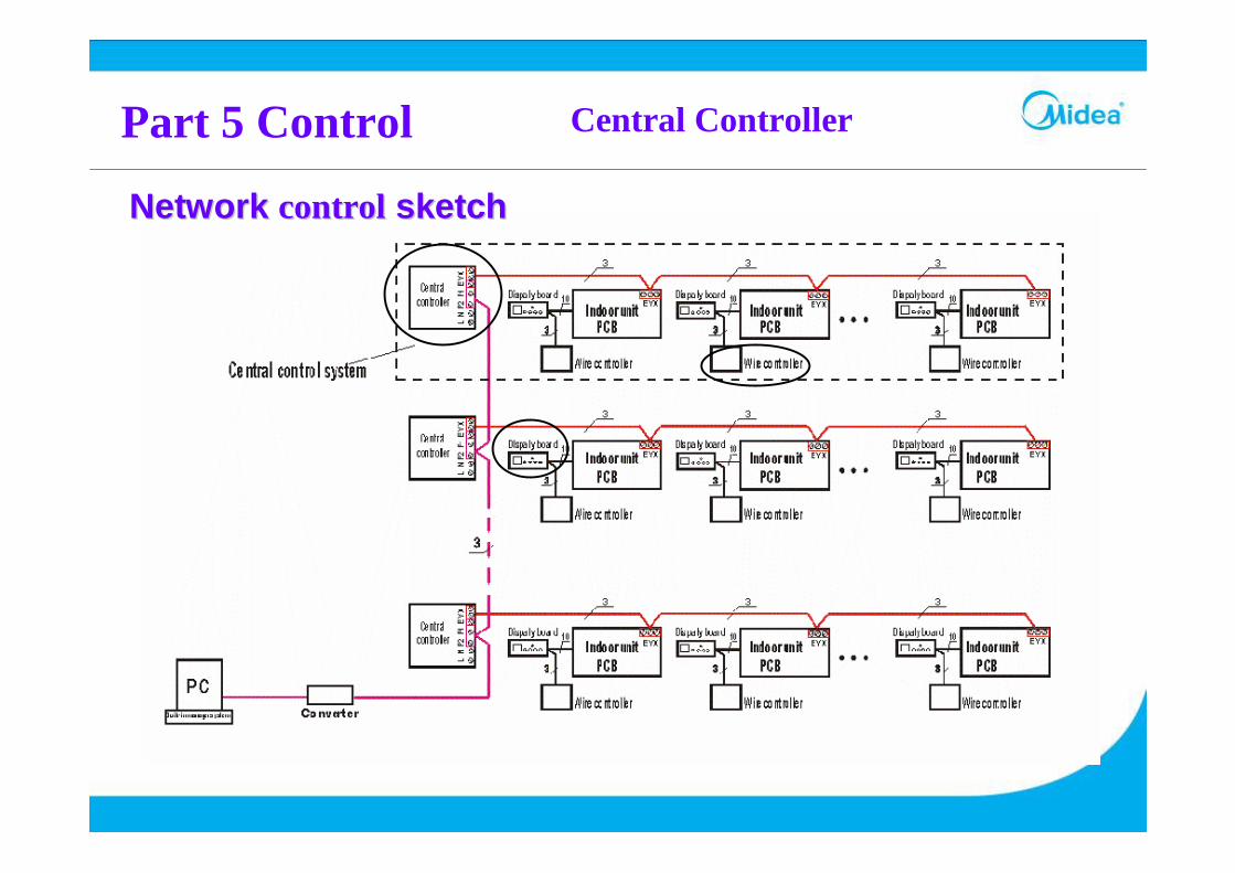
Network Network controlcontrol sketchsketch
Part 5 Control Central Controller
New!
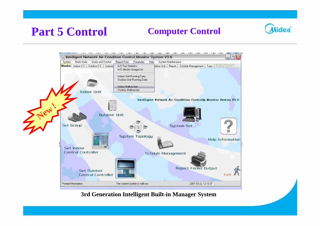
Part 5 Control Computer Control
3rd Generation Intelligent Built-in Manager System
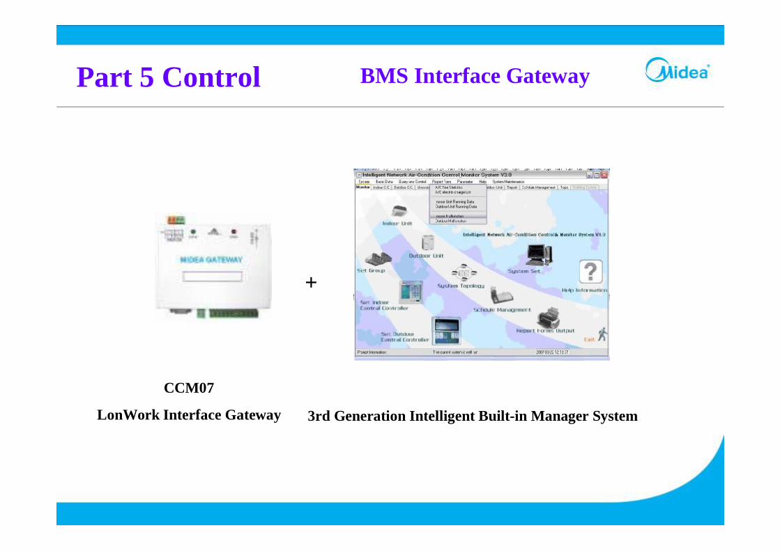
Part 5 Control BMS Interface Gateway
+
3rd Generation Intelligent Built-in Manager System
CCM07
LonWork Interface Gateway

Part 5 Control
CCM08
Central Controller Built-in LonWork/BACNET Interface
Central Controller Built-in BMS Interface

Thank You!
Creates A Better Life