Embed Size (px)
Citation preview
SGP-SI series Solar Pumping Inverter
Solar Pumping Inverter User Manual
Figure 1 SGP solar pumping inverter
www.sgp-france.com
2 / 19
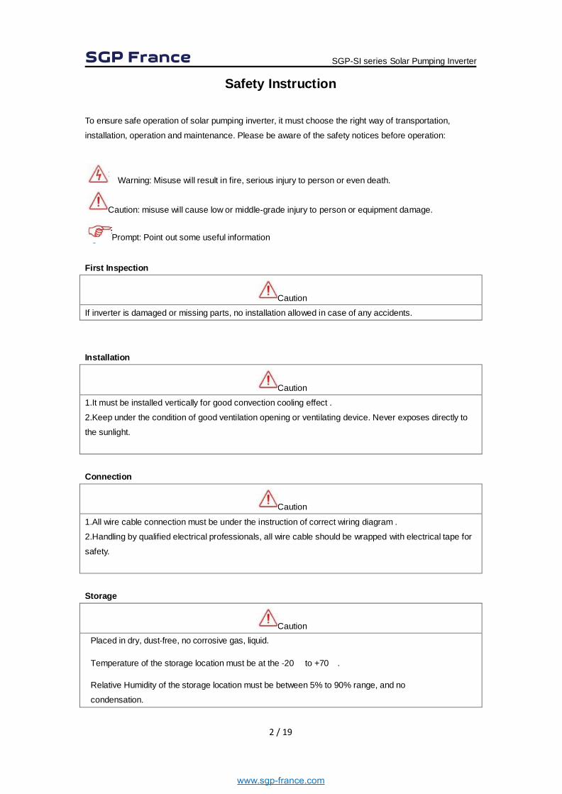
Safety Instruction To ensure safe operation of solar pumping inverter, it must choose the right way of transportation,
installation, operation and maintenance. Please be aware of the safety notices before operation:
Warning: Misuse will result in fire, serious injury to person or even death.
Caution: misuse will cause low or middle-grade injury to person or equipment damage.
Prompt: Point out some useful information
First Inspection
Caution
If inverter is damaged or missing parts, no installation allowed in case of any accidents.
Installation
Caution
1.It must be installed vertically for good convection cooling effect .
2.Keep under the condition of good ventilation opening or ventilating device. Never exposes directly to
the sunlight.
Connection
Caution
1.All wire cable connection must be under the instruction of correct wiring diagram .
2.Handling by qualified electrical professionals, all wire cable should be wrapped with electrical tape for
safety.
Storage
Caution Placed in dry, dust‐free, no corrosive gas, liquid.
Temperature of the storage location must be at the ‐20℃ to +70℃.
Relative Humidity of the storage location must be between 5% to 90% range, and no
condensation.
SGP-SI series Solar Pumping Inverter
www.sgp-france.com
3 / 19
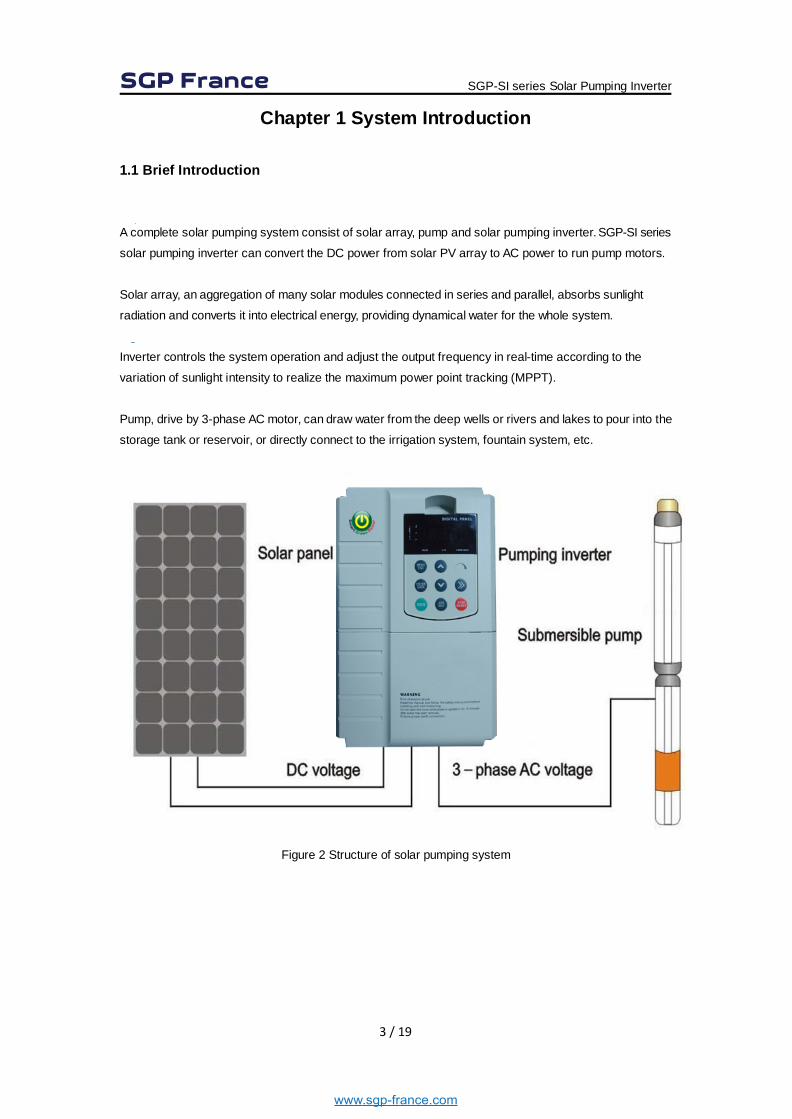
Chapter 1 System Introduction 1.1 Brief Introduction A complete solar pumping system consist of solar array, pump and solar pumping inverter. SGP-SI series
solar pumping inverter can convert the DC power from solar PV array to AC power to run pump motors.
Solar array, an aggregation of many solar modules connected in series and parallel, absorbs sunlight
radiation and converts it into electrical energy, providing dynamical water for the whole system.
Inverter controls the system operation and adjust the output frequency in real-time according to the
variation of sunlight intensity to realize the maximum power point tracking (MPPT).
Pump, drive by 3-phase AC motor, can draw water from the deep wells or rivers and lakes to pour into the
storage tank or reservoir, or directly connect to the irrigation system, fountain system, etc.
Figure 2 Structure of solar pumping system
SGP-SI series Solar Pumping Inverter
www.sgp-france.com
4 / 19
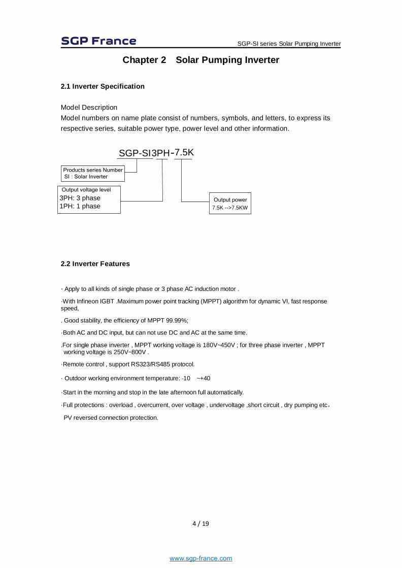
Chapter 2 Solar Pumping Inverter 2.1 Inverter Specification Model Description Model numbers on name plate consist of numbers, symbols, and letters, to express its respective series, suitable power type, power level and other information.
-Products series NumberSI : Solar Inverter
Output voltage level
Output power
2.2 Inverter Features
· Apply to all kinds of single phase or 3 phase AC induction motor .
·With Infineon IGBT .Maximum power point tracking (MPPT) algorithm for dynamic VI, fast response speed,
. Good stability, the efficiency of MPPT 99.99%;
·Both AC and DC input, but can not use DC and AC at the same time.
.For single phase inverter , MPPT working voltage is 180V~450V ; for three phase inverter , MPPT working voltage is 250V~800V .
·Remote control , support RS323/RS485 protocol.
· Outdoor working environment temperature: ‐10℃~+40℃
·Start in the morning and stop in the late afternoon full automatically.
·Full protections : overload , overcurrent, over voltage , undervoltage ,short circuit , dry pumping etc,
PV reversed connection protection.
SGP-SI series Solar Pumping Inverter
SGP-SI3PH 7.5K
3PH: 3 phase1PH: 1 phase
www.sgp-france.com
7.5K -->7.5KW
5 / 19
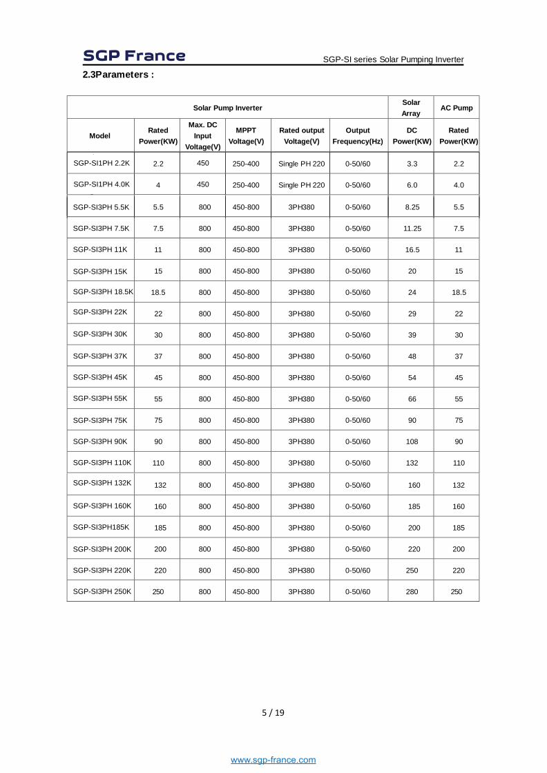
2.3Parameters :
Solar Pump Inverter Solar Array
AC Pump
Model Rated
Power(KW)
Max. DC Input
Voltage(V)
MPPT Voltage(V)
Rated output Voltage(V)
Output Frequency(Hz)
DC Power(KW)
Rated Power(KW)
2.2 450 250-400 Single PH 220 0-50/60 3.3 2.2
4 450 250-400 Single PH 220 0-50/60 6.0 4.0
5.5 800 450-800 3PH380 0-50/60 8.25 5.5
7.5 800 450-800 3PH380 0-50/60 11.25 7.5
11 800 450-800 3PH380 0-50/60 16.5 11
15 800 450-800 3PH380 0-50/60 20 15
18.5 800 450-800 3PH380 0-50/60 24 18.5
22 800 450-800 3PH380 0-50/60 29 22
30 800 450-800 3PH380 0-50/60 39 30
37 800 450-800 3PH380 0-50/60 48 37
45 800 450-800 3PH380 0-50/60 54 45
55 800 450-800 3PH380 0-50/60 66 55
75 800 450-800 3PH380 0-50/60 90 75
90 800 450-800 3PH380 0-50/60 108 90
110 800 450-800 3PH380 0-50/60 132 110
SGP-SI series Solar Pumping Inverter
www.sgp-france.com
SGP-SI1PH 2.2K
SGP-SI1PH 4.0K
SGP-SI3PH 5.5K
SGP-SI3PH 7.5K
SGP-SI3PH 11K
SGP-SI3PH 15K
SGP-SI3PH 18.5K
SGP-SI3PH 22K
SGP-SI3PH 30K
SGP-SI3PH 37K
SGP-SI3PH 45K
SGP-SI3PH 55K
SGP-SI3PH 75K
SGP-SI3PH 90K
SGP-SI3PH 110K
132 800 450-800 3PH380 0-50/60 160
160 800 450-800 3PH380 0-50/60 185
185 800 450-800 3PH380 0-50/60 200
200 800 450-800 3PH380 0-50/60 220
220 800 450-800 3PH380 0-50/60 250
250 800 450-800 3PH380 0-50/60 280
SGP-SI3PH185K
SGP-SI3PH 200K
SGP-SI3PH 220K
SGP-SI3PH 250K
SGP-SI3PH 132K
SGP-SI3PH 160K
132
160
185
200
220
250

6 / 19
2.3Parameters :
Solar Pump Inverter Solar Array
AC Pump
Model Rated
Power(KW)
Max. DC Input
Voltage(V)
MPPT Voltage(V)
Rated output Voltage(V)
Output Frequency(Hz)
DC Power(KW)
Rated Power(KW)
SGP-SI series Solar Pumping Inverter
www.sgp-france.com
280 800 450-800 3PH380 0-50/60 315
315 800 450-800 3PH380 0-50/60 355
SGP-SI3PH 280K
SGP-SI3PH 315K
355 800 450-800 3PH380 0-50/60 400
400 800 450-800 3PH380 0-50/60 450
455 800 450-800 3PH380 0-50/60 500
500 800 450-800 3PH380 0-50/60 560
560 800 450-800 3PH380 0-50/60 630
630 800 450-800 3PH380 0-50/60 710
SGP-SI3PH 455K
SGP-SI3PH 500K
SGP-SI3PH 560K
SGP-SI3PH 630K
SGP-SI3PH 355K
SGP-SI3PH 400K
280
315
355
400
455
500
560
630
7 / 19
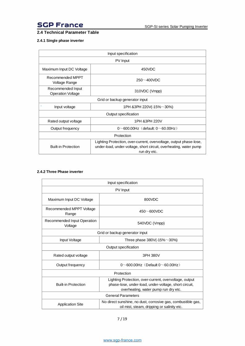
2.4 Technical Parameter Table
2.4.1 Single phase inverter
Input specification
PV Input
Maximum Input DC Voltage 450VDC
Recommended MPPT Voltage Range 250~400VDC
Recommended Input Operation Voltage 310VDC (Vmpp)
Grid or backup generator input
Input voltage 1PH &3PH 220V(-15%~30%)
Output specification
Rated output voltage 1PH &3PH 220V
Output frequency 0~600.00Hz(default: 0~60.00Hz)
Protection
Built-in Protection Lighting Protection, over-current, overvoltage, output phase-lose, under-load, under-voltage, short circuit, overheating, water pump
run dry etc. 2.4.2 Three Phase inverter
Input specification
PV Input
Maximum Input DC Voltage 800VDC
Recommended MPPT Voltage Range 450~600VDC
Recommended Input Operation Voltage 540VDC (Vmpp)
Grid or backup generator input
Input Voltage Three phase 380V(-15%~30%)
Output specification
Rated output voltage 3PH 380V
Output frequency 0~600.00Hz(Default 0~60.00Hz)
Protection
Built-in Protection Lighting Protection, over-current, overvoltage, output phase-lose, under-load, under-voltage, short circuit,
overheating, water pump run dry etc. General Parameters
Application Site No direct sunshine, no dust, corrosive gas, combustible gas, oil mist, steam, dripping or salinity etc.
SGP-SI series Solar Pumping Inverter
www.sgp-france.com
8 / 19
Altitude 0~2000 m
Derated use above 1000m,per 100m, the rated output current decrease 1%.
Environment Temperature -10℃~40℃ (Environment Temperature be 40℃~50℃, please keep derated use.)
Humidity 5~95%,non-condensation
Vibration less than 5.9 m/s2(0.6g)
Storage Temperature -20℃~+70℃
Efficiency Rated Power Run≥93%
Installation Wall or rail mounting
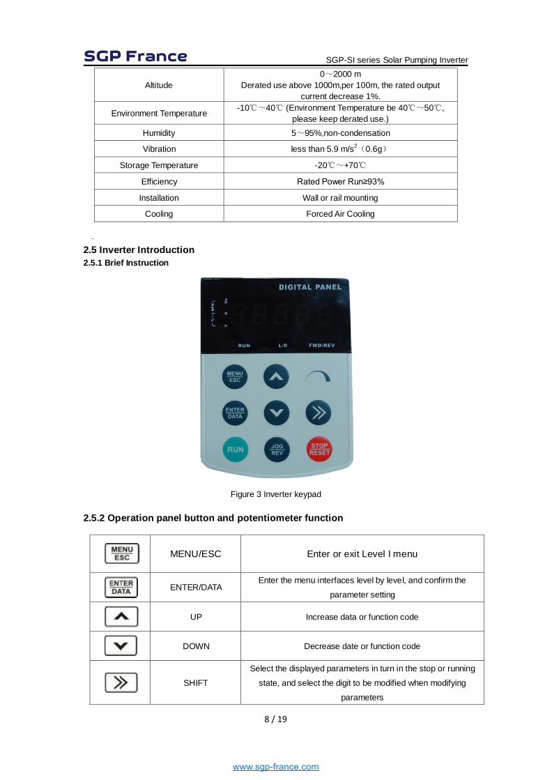
Cooling Forced Air Cooling 2.5 Inverter Introduction 2.5.1 Brief Instruction
Figure 3 Inverter keypad 2.5.2 Operation panel button and potentiometer function
MENU/ESC Enter or exit Level I menu
ENTER/DATA
Enter the menu interfaces level by level, and confirm the
parameter setting
UP Increase data or function code
DOWN Decrease date or function code
SHIFT
Select the displayed parameters in turn in the stop or running
state, and select the digit to be modified when modifying
parameters
SGP-SI series Solar Pumping Inverter
www.sgp-france.com
9 / 19
RUN Start the inverter in the keypad control mode
STOP/RESET
Stop the inverter when it is in the running state and perform the
reset operation when it is in the fault state
JOG/REV
Perform function switchover (such as jog run and quick
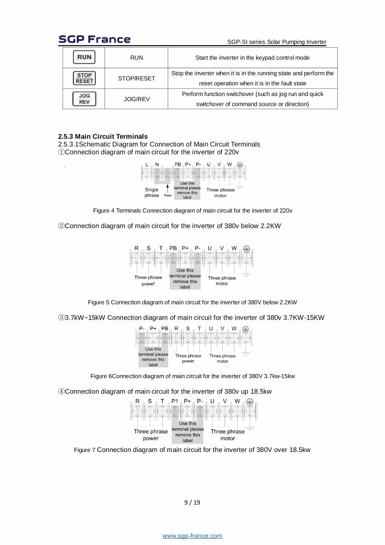
switchover of command source or direction) 2.5.3 Main Circuit Terminals 2.5.3.1Schematic Diagram for Connection of Main Circuit Terminals ①Connection diagram of main circuit for the inverter of 220v
Figure 4 Terminals Connection diagram of main circuit for the inverter of 220v
②Connection diagram of main circuit for the inverter of 380v below 2.2KW
Figure 5 Connection diagram of main circuit for the inverter of 380V below 2.2KW ③3.7kW~15kW Connection diagram of main circuit for the inverter of 380v 3.7KW-15KW
Figure 6Connection diagram of main circuit for the inverter of 380V 3.7kw-15kw
④Connection diagram of main circuit for the inverter of 380v up 18.5kw
Figure 7 Connection diagram of main circuit for the inverter of 380V over 18.5kw
SGP-SI series Solar Pumping Inverter
www.sgp-france.com
10 / 19
2.5.3.2 Instructions of main circuit terminals of inverter:
Terminals Function Instruction
L,N single-phase 220V input terminal, external connection of grid single phase 220V AC power
R,S,T input terminal of AC 3-phase power, external connection of grid 3phase AC power U,V,W output terminal of 3phase power, external connection of AC 3phase motor
P+,P- Negative and positive terminals of DC power, external connection of brake unit terminal
P+,PB External connecting of brake resistor terminal P1,P+ External connection of DC electric reactor terminal
Earth terminal
DANGER ● the voltage class of VD300A series inverter 3phase power has 2 class: 220V, 380V, before connecting power, please make sure the power class on inverter nameplate is the same with the accessing power. Otherwise do not connect. ● DC bus P+ P-terminal: take note that when power outrage there is residual voltage on DC bus P+ P- terminal, need to wait for a while until CHARGE LED off. Otherwise it is danger of electric shock. ●When selecting external brake unit, note the polarity of P= P- cannot be reversely connected, otherwise it can result in damage or even fire. Do not directly connect brake resistor to DC bus, it may result damage or fire.
WARNING
1) Input power L,N or R, S T: the cable connection at input side of the inverter has no phase sequence requirement. 2) Brake unit cable length should not exceed 10m, twisted pair or double cable parallel wiring should be used. 3)Brake resistor connecting terminal P+ P-: confirm whether the device has built-in brake unit, its brake resistor connecting terminal is effect. The brake resistor selection table 2-4 recommending value and the wiring distance should less than 5M. Other it can damage inverter. 4)External DC electric reactor connecting terminal P1 P+: for external DC reactor to 18.5Kw and above power inverter, get rid off the connector between P1 P+ terminal during installation, reactor is installed between the 2 terminal. 5)Inverter output side U V W: the output side cannot connect capacitor or surge absorber, otherwise it will affect inverter in self-protection frequently or damage. 6)In case the motor cable is too long, it may generate electrical resonance easily due to the impact of distributed capacitance, thus damaging the motor insulation or generating higher leakage current to invoke over current protection of the inverter. When the length of motor cables longer than 100 meters, it needs to install a AC output reactor. 7)Earth terminal PE: This terminal shall be earthed reliably, with resistance of earth cable of less than 10Ω.Otherwise, it may cause fault or damage the inverter. Do not share the earth terminal with zero line N terminal, otherwise it will result equipment abnormal running or damage.
SGP-SI series Solar Pumping Inverter
www.sgp-france.com
11 / 19
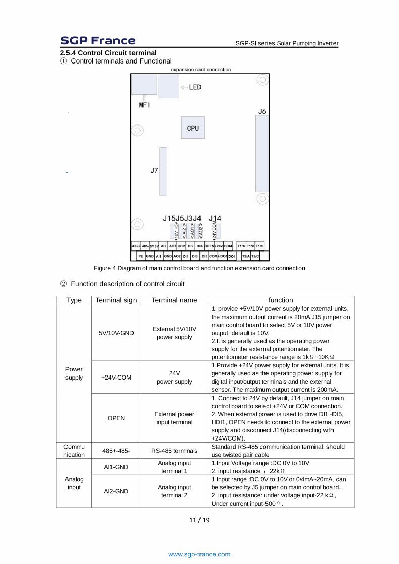
2.5.4 Control Circuit terminal ① Control terminals and Functional
Figure 4 Diagram of main control board and function extension card connection
② Function description of control circuit
Type Terminal sign Terminal name function
Power supply
5V/10V-GND External 5V/10V power supply
1. provide +5V/10V power supply for external-units, the maximum output current is 20mA.J15 jumper on main control board to select 5V or 10V power output, default is 10V. 2.It is generally used as the operating power supply for the external potentiometer. The potentiometer resistance range is 1kΩ~10KΩ
+24V-COM 24V power supply
1.Provide +24V power supply for external units. It is generally used as the operating power supply for digital input/output terminals and the external sensor. The maximum output current is 200mA.
OPEN External power input terminal
1. Connect to 24V by default, J14 jumper on main control board to select +24V or COM connection. 2. When external power is used to drive DI1~DI5, HDI1, OPEN needs to connect to the external power supply and disconnect J14(disconnecting with +24V/COM).
Commu nication 485+-485- RS-485 terminals Standard RS-485 communication terminal, should
use twisted pair cable
Analog input
AI1-GND Analog input terminal 1
1.Input Voltage range :DC 0V to 10V 2. input resistance :22kΩ
AI2-GND Analog input terminal 2
1.Input range :DC 0V to 10V or 0/4mA~20mA, can be selected by J5 jumper on main control board. 2. input resistance: under voltage input-22 kΩ, Under current input-500Ω.
SGP-SI series Solar Pumping Inverter
www.sgp-france.com
12 / 19
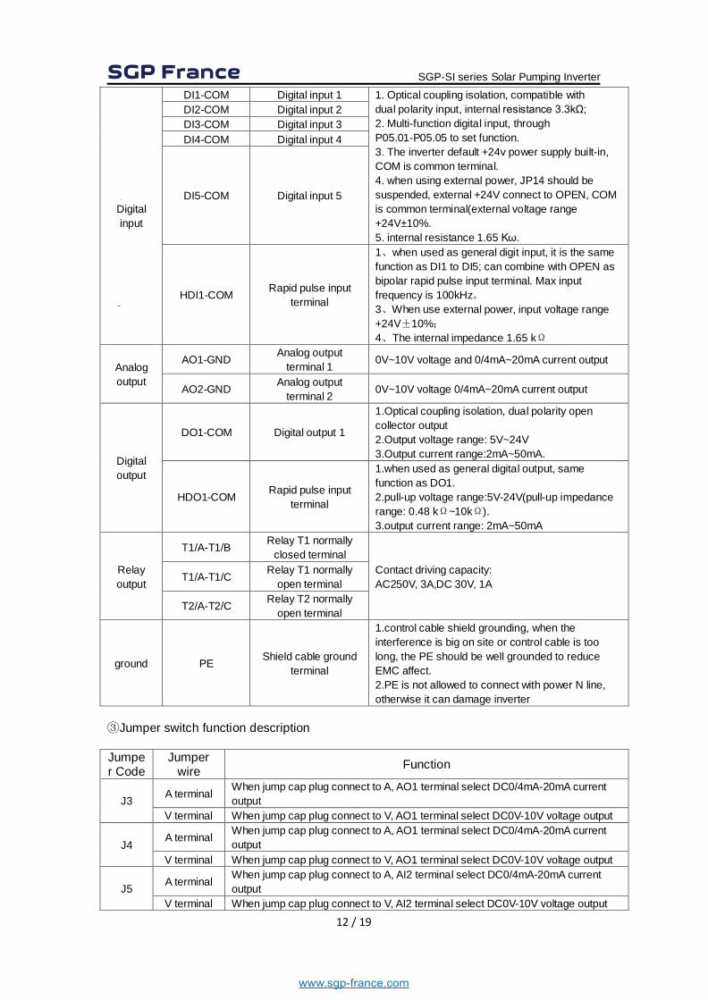
Digital input
DI1-COM Digital input 1 1. Optical coupling isolation, compatible with dual polarity input, internal resistance 3.3kΩ; 2. Multi-function digital input, through P05.01-P05.05 to set function. 3. The inverter default +24v power supply built-in, COM is common terminal. 4. when using external power, JP14 should be suspended, external +24V connect to OPEN, COM is common terminal(external voltage range +24V±10%. 5. internal resistance 1.65 Kω.
DI2-COM Digital input 2 DI3-COM Digital input 3 DI4-COM Digital input 4
DI5-COM Digital input 5
HDI1-COM Rapid pulse input terminal
1、when used as general digit input, it is the same function as DI1 to DI5; can combine with OPEN as bipolar rapid pulse input terminal. Max input frequency is 100kHz。 3、When use external power, input voltage range +24V±10%; 4、The internal impedance 1.65 kΩ
Analog output
AO1-GND Analog output terminal 1 0V~10V voltage and 0/4mA~20mA current output
AO2-GND Analog output terminal 2 0V~10V voltage 0/4mA~20mA current output
Digital output
DO1-COM Digital output 1
1.Optical coupling isolation, dual polarity open collector output 2.Output voltage range: 5V~24V 3.Output current range:2mA~50mA.
HDO1-COM Rapid pulse input terminal
1.when used as general digital output, same function as DO1. 2.pull-up voltage range:5V-24V(pull-up impedance range: 0.48 kΩ~10kΩ). 3.output current range: 2mA~50mA
Relay output
T1/A-T1/B Relay T1 normally closed terminal
Contact driving capacity: AC250V, 3A,DC 30V, 1A T1/A-T1/C Relay T1 normally
open terminal
T2/A-T2/C Relay T2 normally open terminal
ground PE Shield cable ground terminal
1.control cable shield grounding, when the interference is big on site or control cable is too long, the PE should be well grounded to reduce EMC affect. 2.PE is not allowed to connect with power N line, otherwise it can damage inverter
③Jumper switch function description Jumper Code
Jumper wire Function
J3 A terminal When jump cap plug connect to A, AO1 terminal select DC0/4mA-20mA current output
V terminal When jump cap plug connect to V, AO1 terminal select DC0V-10V voltage output
J4 A terminal When jump cap plug connect to A, AO1 terminal select DC0/4mA-20mA current
output V terminal When jump cap plug connect to V, AO1 terminal select DC0V-10V voltage output
J5 A terminal When jump cap plug connect to A, AI2 terminal select DC0/4mA-20mA current output
V terminal When jump cap plug connect to V, AI2 terminal select DC0V-10V voltage output
SGP-SI series Solar Pumping Inverter
www.sgp-france.com
13 / 19
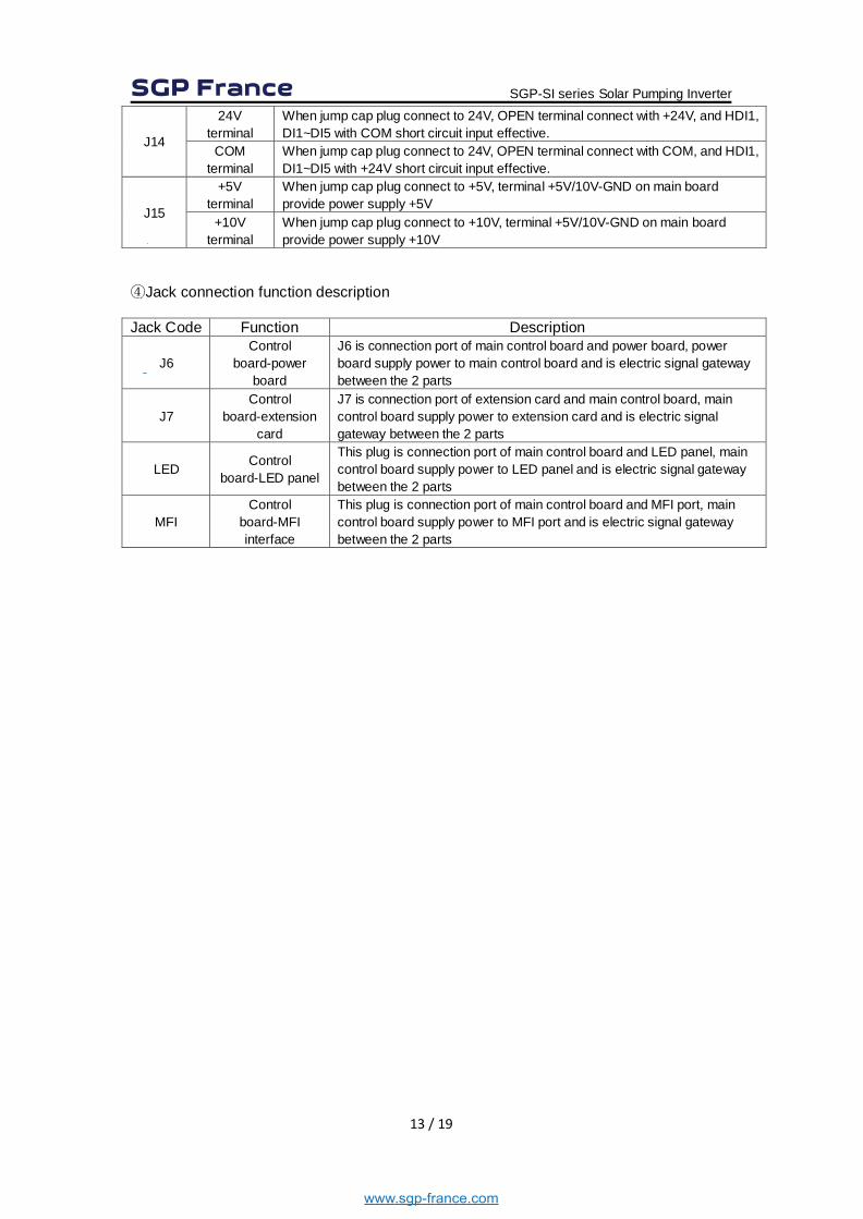
J14
24V terminal
When jump cap plug connect to 24V, OPEN terminal connect with +24V, and HDI1, DI1~DI5 with COM short circuit input effective.
COM terminal
When jump cap plug connect to 24V, OPEN terminal connect with COM, and HDI1, DI1~DI5 with +24V short circuit input effective.
J15
+5V terminal
When jump cap plug connect to +5V, terminal +5V/10V-GND on main board provide power supply +5V
+10V terminal
When jump cap plug connect to +10V, terminal +5V/10V-GND on main board provide power supply +10V
④Jack connection function description Jack Code Function Description
J6 Control
board-power board
J6 is connection port of main control board and power board, power board supply power to main control board and is electric signal gateway between the 2 parts
J7 Control
board-extension card
J7 is connection port of extension card and main control board, main control board supply power to extension card and is electric signal gateway between the 2 parts
LED Control board-LED panel
This plug is connection port of main control board and LED panel, main control board supply power to LED panel and is electric signal gateway between the 2 parts
MFI Control
board-MFI interface
This plug is connection port of main control board and MFI port, main control board supply power to MFI port and is electric signal gateway between the 2 parts
SGP-SI series Solar Pumping Inverter
www.sgp-france.com

14 / 19
2.5.5 Tank water full and Well water dry protection: Tips:
1use the signal wire connect some screw or conductor to put the sensor inside the well or tank;
2use the water as conductor to connect A, B or disconnect A, B to control the pump inverter ;
A, Tank water full protection
B, Well water dry protection
Put the yellow ring where you want to stop the pump
Put the orange B about 0.5 meter lower than yellow A
Reminder: 1, only two ring connected by water, and that can stop the pump; when disconnect in air or only one in water, pump continue its working. 2, the distance 0.5meter means not too close that stop the pump without water full, or not too far away that can’t connect each other even both of them inside water. 3, Yellow A and Orange B can exchange the position.
Put the Red A above the pump motor
Put Black B about 0.5 meter lower than Red A
Reminder: 1, only two ring disconnected from water, and that can stop the pump; when connect inside the water, pump continue its working. 2, the distance 0.5meter means not too close that cann’t stop the pump when water dry, or not too far away that pump cann’t start since always disconnected . 3, Red A and Black B can exchange the position.
Important remark:
For water dry protection, after the sensor connected ready, we need set: P11.33 = 1. For water full protection, no need parameter setting. For the Screw or conductor, we'd better use Anti-oxidant material. otherwise, we need to change a new one in case of rusty or corrosion after few months.
SGP-SI series Solar Pumping Inverter
www.sgp-france.com
15 / 19
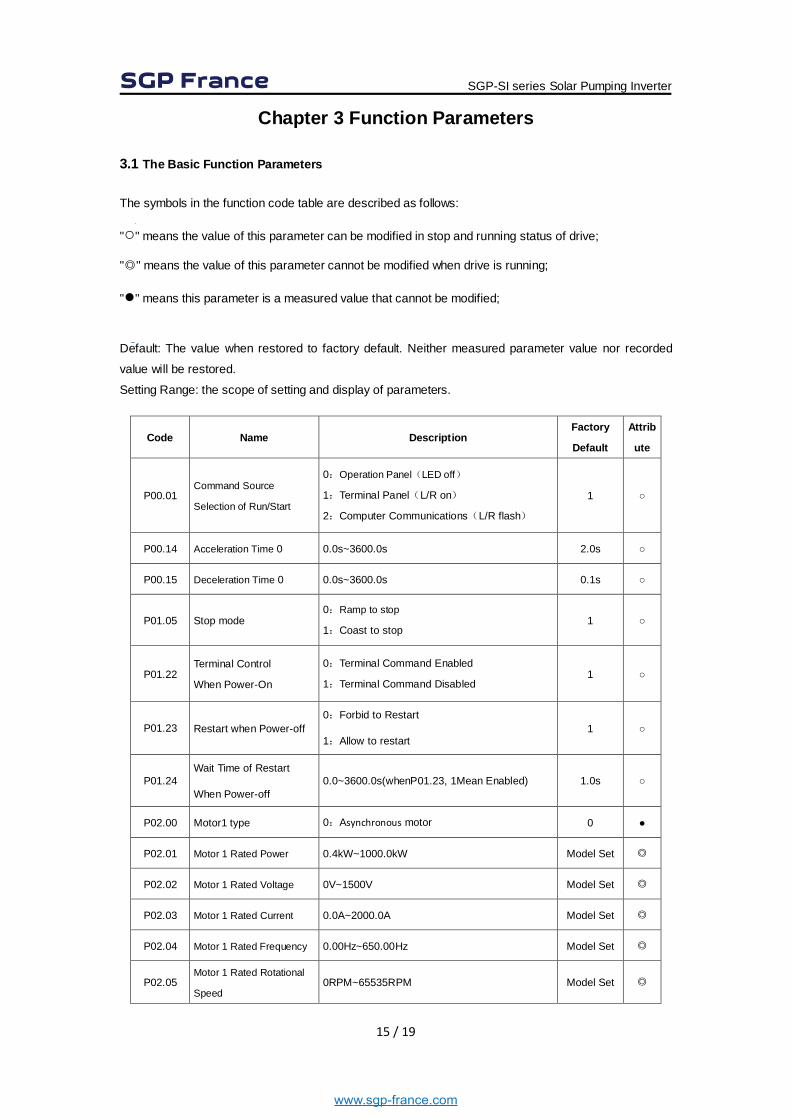
Chapter 3 Function Parameters 3.1 The Basic Function Parameters The symbols in the function code table are described as follows:
"○" means the value of this parameter can be modified in stop and running status of drive;
"◎" means the value of this parameter cannot be modified when drive is running;
"●" means this parameter is a measured value that cannot be modified;
Default: The value when restored to factory default. Neither measured parameter value nor recorded
value will be restored.
Setting Range: the scope of setting and display of parameters.
Code Name Description Factory
Default
Attrib
ute
P00.01 Command Source
Selection of Run/Start
0:Operation Panel(LED off)
1:Terminal Panel(L/R on)
2:Computer Communications(L/R flash)
1 ○
P00.14 Acceleration Time 0 0.0s~3600.0s 2.0s ○
P00.15 Deceleration Time 0 0.0s~3600.0s 0.1s ○
P01.05 Stop mode 0:Ramp to stop
1:Coast to stop 1 ○
P01.22 Terminal Control
When Power-On
0:Terminal Command Enabled
1:Terminal Command Disabled 1 ○
P01.23 Restart when Power-off 0:Forbid to Restart
1:Allow to restart 1 ○
P01.24 Wait Time of Restart
When Power-off 0.0~3600.0s(whenP01.23, 1Mean Enabled) 1.0s ○
P02.00 Motor1 type 0:Asynchronous motor 0 ●
P02.01 Motor 1 Rated Power 0.4kW~1000.0kW Model Set ◎
P02.02 Motor 1 Rated Voltage 0V~1500V Model Set ◎
P02.03 Motor 1 Rated Current 0.0A~2000.0A Model Set ◎
P02.04 Motor 1 Rated Frequency 0.00Hz~650.00Hz Model Set ◎
P02.05 Motor 1 Rated Rotational
Speed 0RPM~65535RPM Model Set ◎
SGP-SI series Solar Pumping Inverter
www.sgp-france.com
16 / 19
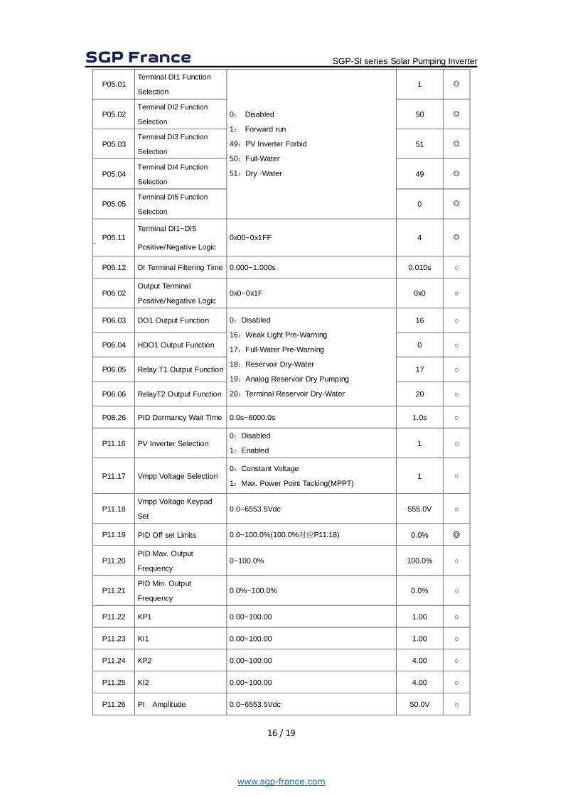
P05.01 Terminal DI1 Function
Selection
0: Disabled
1: Forward run
49:PV Inverter Forbid
50:Full-Water
51:Dry -Water
1 ◎
P05.02 Terminal DI2 Function
Selection 50 ◎
P05.03 Terminal DI3 Function
Selection 51 ◎
P05.04 Terminal DI4 Function
Selection 49 ◎
P05.05 Terminal DI5 Function
Selection 0 ◎
P05.11 Terminal DI1~DI5
Positive/Negative Logic 0x00~0x1FF 4 ◎
P05.12 DI Terminal Filtering Time 0.000~1.000s 0.010s ○
P06.02 Output Terminal
Positive/Negative Logic 0x0~0x1F 0x0 ○
P06.03 DO1 Output Function 0:Disabled
16:Weak Light Pre-Warning
17:Full-Water Pre-Warning
18:Reservoir Dry-Water
19:Analog Reservoir Dry Pumping
20:Terminal Reservoir Dry-Water
16 ○
P06.04 HDO1 Output Function 0 ○
P06.05 Relay T1 Output Function 17 ○
P06.06 RelayT2 Output Function 20 ○
P08.26 PID Dormancy Wait Time 0.0s~6000.0s 1.0s ○
P11.16 PV Inverter Selection 0:Disabled
1:Enabled 1 ○
P11.17 Vmpp Voltage Selection 0:Constant Voltage
1:Max. Power Point Tacking(MPPT) 1 ○
P11.18 Vmpp Voltage Keypad
Set 0.0~6553.5Vdc 555.0V ○
P11.19 PID Off set Limits 0.0~100.0%(100.0%对应P11.18) 0.0% ◎
P11.20 PID Max. Output
Frequency 0~100.0% 100.0% ○
P11.21 PID Min. Output
Frequency 0.0%~100.0% 0.0% ○
P11.22 KP1 0.00~100.00 1.00 ○
P11.23 KI1 0.00~100.00 1.00 ○
P11.24 KP2 0.00~100.00 4.00 ○
P11.25 KI2 0.00~100.00 4.00 ○
P11.26 PI Amplitude 0.0~6553.5Vdc 50.0V ○
SGP-SI series Solar Pumping Inverter
www.sgp-france.com

17 / 19
P11.27
Analog Channel
Selection of Reservoir
Water Level
0:Disabled
1:AI1
2:AI2
3:AI3
0 ○
P11.28 Dry-Water Threshold 0.0~100.0% 25.0% ○
P11.29 Delay Time of Dry-Water 0~10000s 10s ○
P11.30 Wake-up Delay Time of
Dry-Water 0~10000s 300s ○
P11.31 Dry Pumping Threshold 0.0~50.0% 0.0% ○
P11.32 Delay Time of Full-Water 0.0~1000.0s 60.0s ○
P11.33 Dry Pumping Function 0: Disabled
1: Enabled 0 ○
P11.34 Reset Delay of Full-Water 0.0~1000.0s 300.0s ○
P11.35 Frequency of Weak Light 0~50Hz 5.00Hz ○
P11.36 Delay Time of Weak Light 0.0~3600.0s 100.0s ○
P11.37 Reset Delay of Weak
Light 0.0~3600.0s 300.0s ○
P11.38 Reference Voltage of
Given Display 0.0~2000.0V 0V ○
P11.39 Min. Voltage of MPPT 0.0~6553.5Vdc 100.0V ○
P11.40 Max. Voltage of MPPT 0.0~6553.5Vdc 800.0V ○
P14.01 Fault Code
0:No Fault A-LS Warning of Weak Light A-LL Warning of Dry-water A-TF Warning of Full -water Er001:Acceleration Overcurrent(Hardware) Er002:Deceleration Overcurrent(Hardware) Er003:Constant-speed Overcurrent(Hardware) Er004:Acceleration Overcurrent Er005:Deceleration Overcurrent Er006:Constant-speed Overcurrent Er007:Acceleration Overvoltage Er008:Deceleration Overvoltage Er009:Constant-speed Overvoltage Er010:Bus Under voltage protection Er011:Motor Overload Er012:Inverter Overload Er013:Input Open-phase Er014:Output Open-phase Er015:Overheat Er016:Over Current Fault Er017:External Input Fault Er018:Communication Fault
0 ●
SGP-SI series Solar Pumping Inverter
www.sgp-france.com
18 / 19
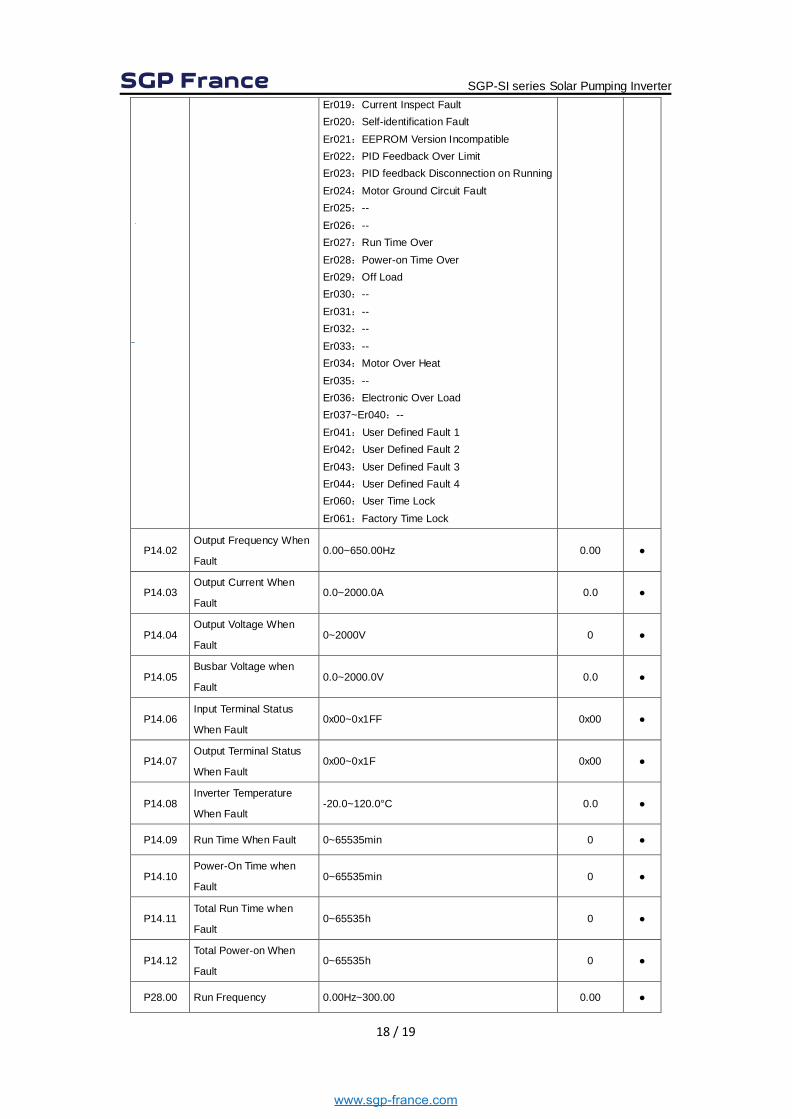
Er019:Current Inspect Fault Er020:Self-identification Fault Er021:EEPROM Version Incompatible Er022:PID Feedback Over Limit Er023:PID feedback Disconnection on Running Er024:Motor Ground Circuit Fault Er025:-- Er026:-- Er027:Run Time Over Er028:Power-on Time Over Er029:Off Load Er030:-- Er031:-- Er032:-- Er033:-- Er034:Motor Over Heat Er035:-- Er036:Electronic Over Load Er037~Er040:-- Er041:User Defined Fault 1 Er042:User Defined Fault 2 Er043:User Defined Fault 3 Er044:User Defined Fault 4 Er060:User Time Lock Er061:Factory Time Lock
P14.02 Output Frequency When
Fault 0.00~650.00Hz 0.00 ●
P14.03 Output Current When
Fault 0.0~2000.0A 0.0 ●
P14.04 Output Voltage When
Fault 0~2000V 0 ●
P14.05 Busbar Voltage when
Fault 0.0~2000.0V 0.0 ●
P14.06 Input Terminal Status
When Fault 0x00~0x1FF 0x00 ●
P14.07 Output Terminal Status
When Fault 0x00~0x1F 0x00 ●
P14.08 Inverter Temperature
When Fault -20.0~120.0°C 0.0 ●
P14.09 Run Time When Fault 0~65535min 0 ●
P14.10 Power-On Time when
Fault 0~65535min 0 ●
P14.11 Total Run Time when
Fault 0~65535h 0 ●
P14.12 Total Power-on When
Fault 0~65535h 0 ●
P28.00 Run Frequency 0.00Hz~300.00 0.00 ●
SGP-SI series Solar Pumping Inverter
www.sgp-france.com
19 / 19
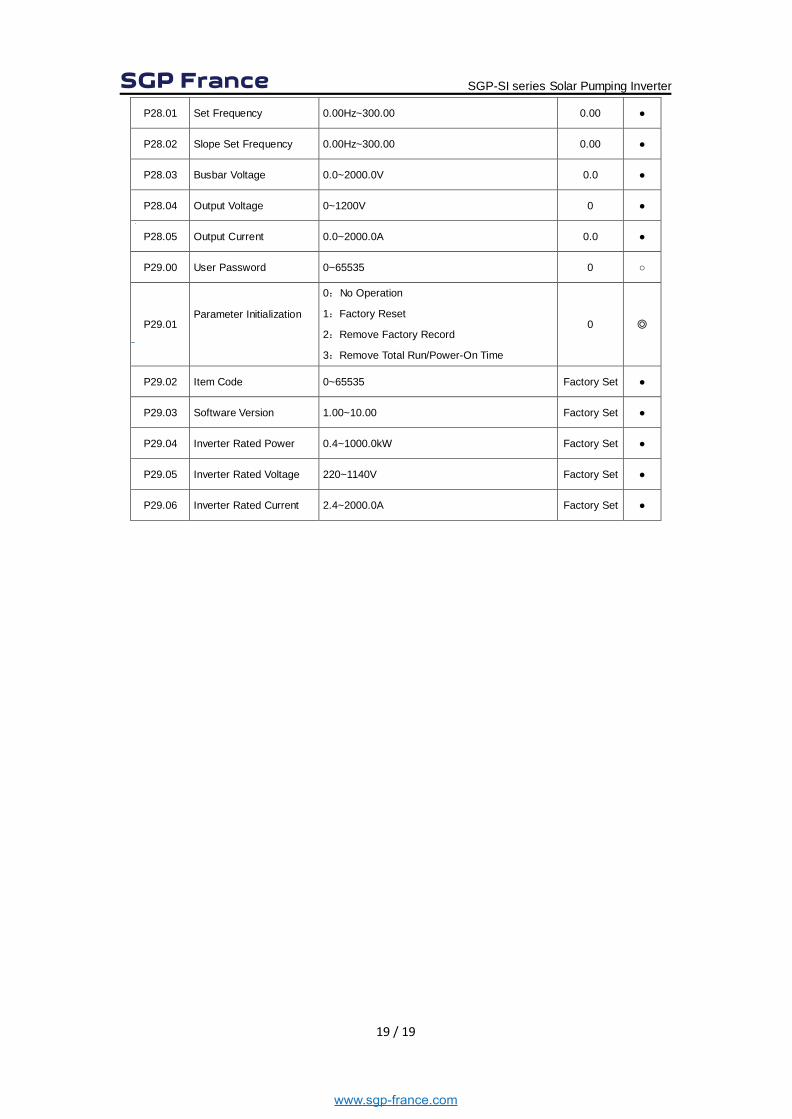
P28.01 Set Frequency 0.00Hz~300.00 0.00 ●
P28.02 Slope Set Frequency 0.00Hz~300.00 0.00 ●
P28.03 Busbar Voltage 0.0~2000.0V 0.0 ●
P28.04 Output Voltage 0~1200V 0 ●
P28.05 Output Current 0.0~2000.0A 0.0 ●
P29.00 User Password 0~65535 0 ○
P29.01 Parameter Initialization
0:No Operation
1:Factory Reset
2:Remove Factory Record
3:Remove Total Run/Power-On Time
0 ◎
P29.02 Item Code 0~65535 Factory Set ●
P29.03 Software Version 1.00~10.00 Factory Set ●
P29.04 Inverter Rated Power 0.4~1000.0kW Factory Set ●
P29.05 Inverter Rated Voltage 220~1140V Factory Set ●
P29.06 Inverter Rated Current 2.4~2000.0A Factory Set ●
SGP-SI series Solar Pumping Inverter
www.sgp-france.com