Embed Size (px)
Citation preview
Inverse Dynamics
D. Gordon E. Robertson, Ph.D.School of Human Kinetics
University of Ottawa
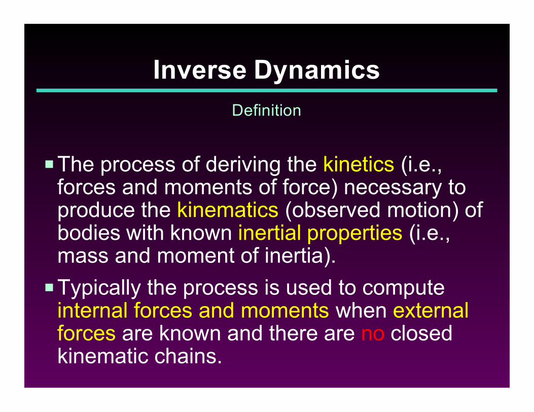
PThe process of deriving the kinetics (i.e.,forces and moments of force) necessary toproduce the kinematics (observed motion) ofbodies with known inertial properties (i.e.,mass and moment of inertia).
PTypically the process is used to computeinternal forces and moments when externalforces are known and there are no closedkinematic chains.
Inverse Dynamics
Definition
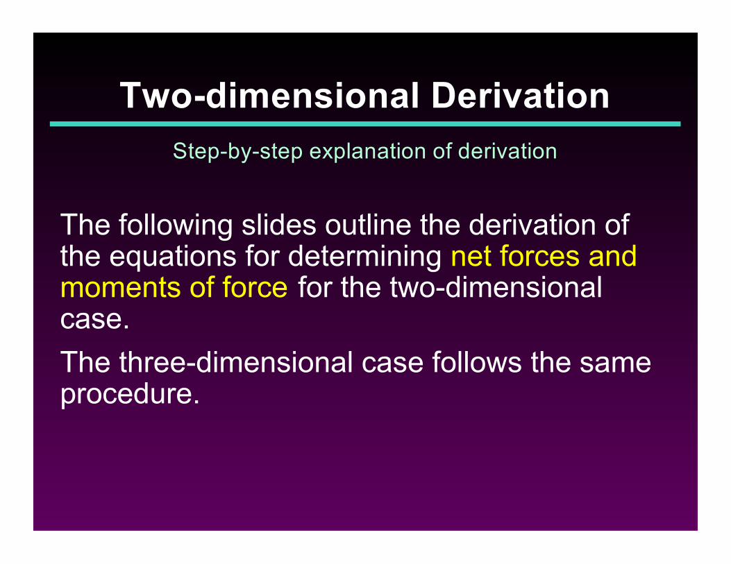
The following slides outline the derivation of the equations for determining net forces andmoments of force for the two-dimensionalcase.
The three-dimensional case follows the sameprocedure.
Two-dimensional Derivation
Step-by-step explanation of derivation
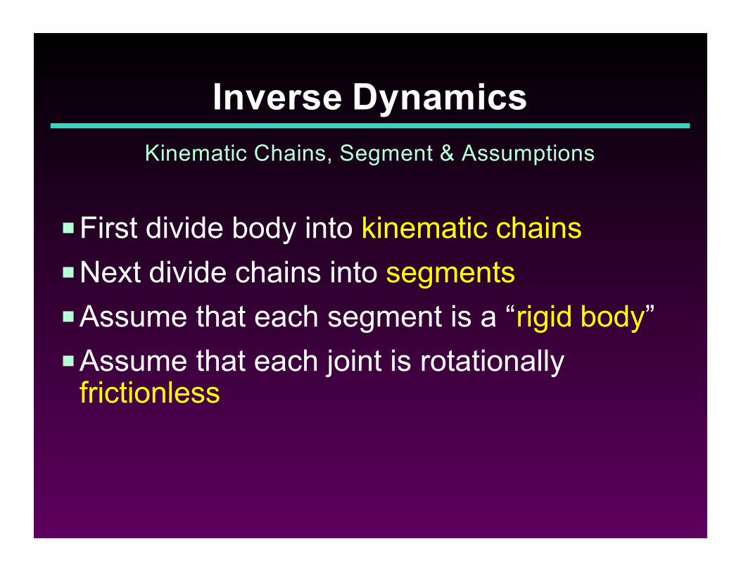
PFirst divide body into kinematic chains
PNext divide chains into segments
PAssume that each segment is a “rigid body”
PAssume that each joint is rotationallyfrictionless
Inverse Dynamics
Kinematic Chains, Segment & Assumptions
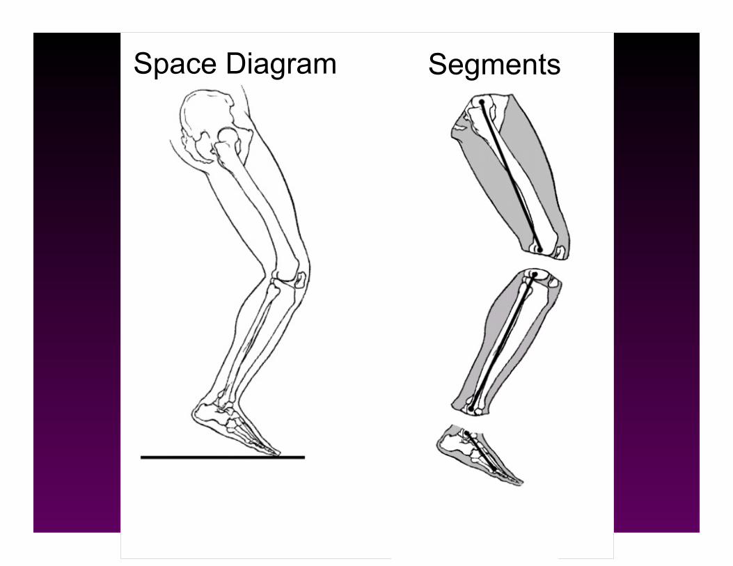
Space Diagram Segments
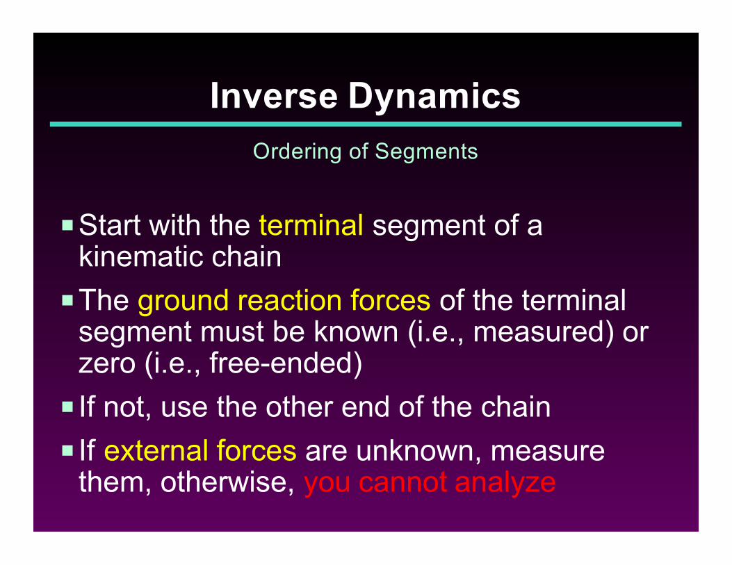
PStart with the terminal segment of akinematic chain
PThe ground reaction forces of the terminalsegment must be known (i.e., measured) orzero (i.e., free-ended)
P If not, use the other end of the chain
P If external forces are unknown, measurethem, otherwise, you cannot analyze
Inverse Dynamics
Ordering of Segments
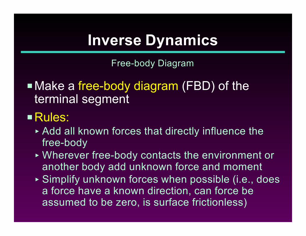
PMake a free-body diagram (FBD) of theterminal segment
PRules:< Add all known forces that directly influence the
free-body< Wherever free-body contacts the environment or
another body add unknown force and moment< Simplify unknown forces when possible (i.e., does
a force have a known direction, can force beassumed to be zero, is surface frictionless)
Inverse Dynamics
Free-body Diagram
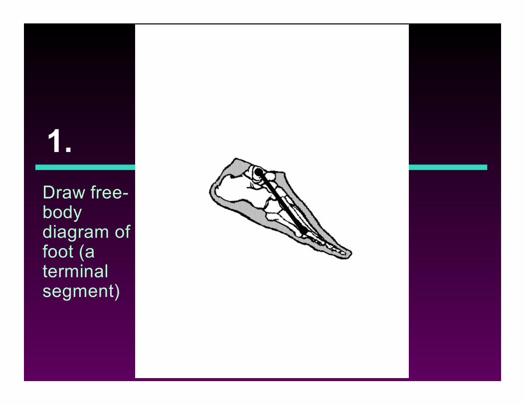
1.
Draw free-bodydiagram offoot (aterminalsegment)
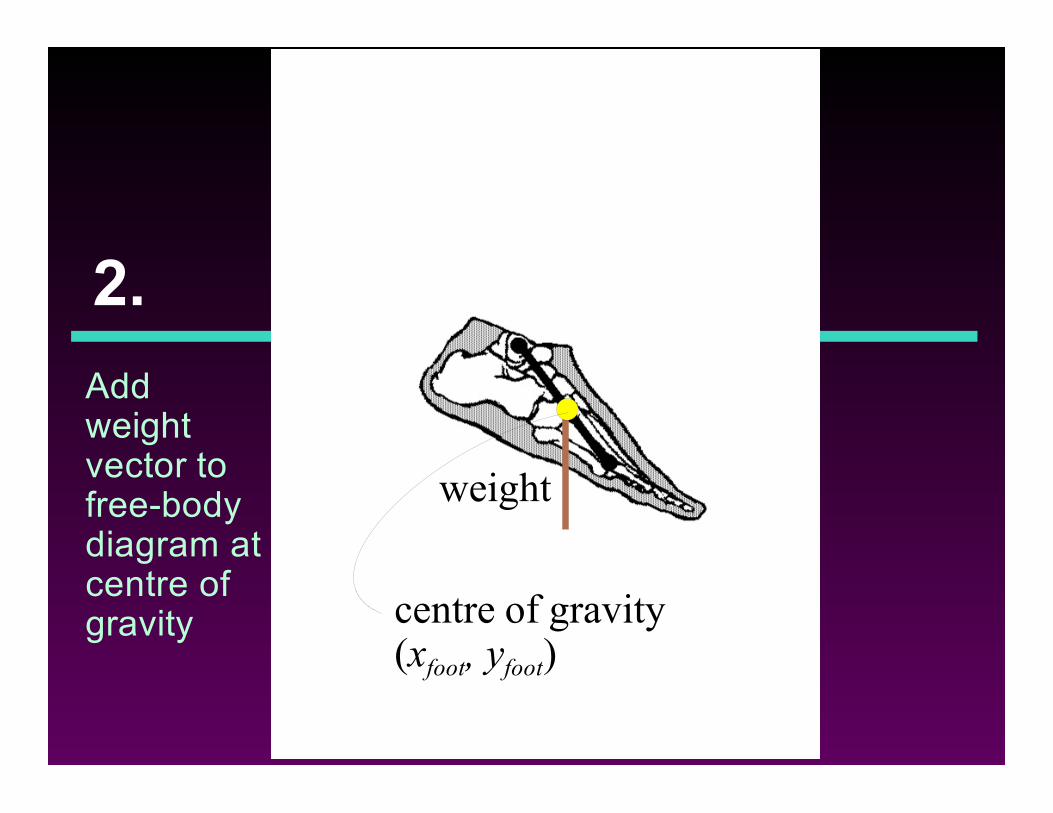
2.
Addweightvector tofree-bodydiagram atcentre ofgravity centre of gravity
(xfoot, yfoot)
weight
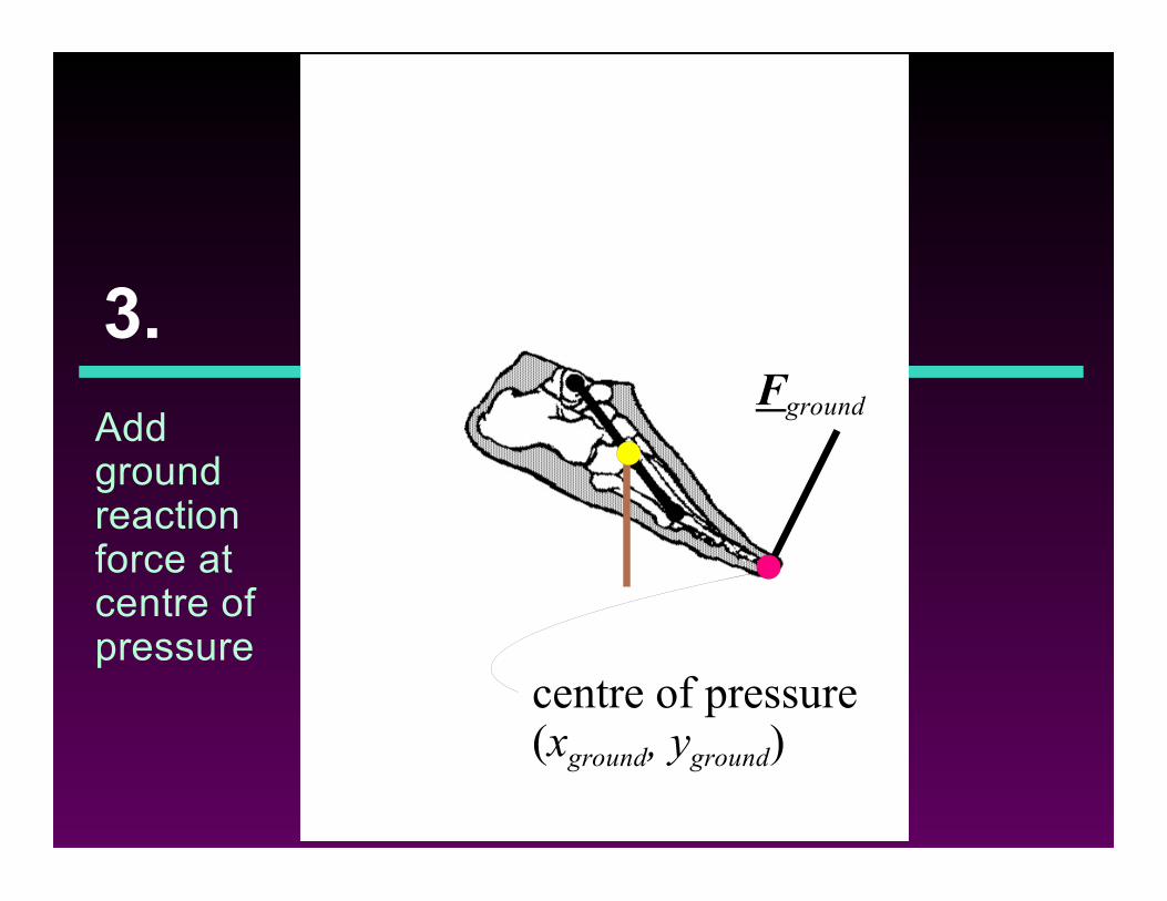
3.
Addgroundreactionforce atcentre ofpressure
Fground
centre of pressure(xground, yground)
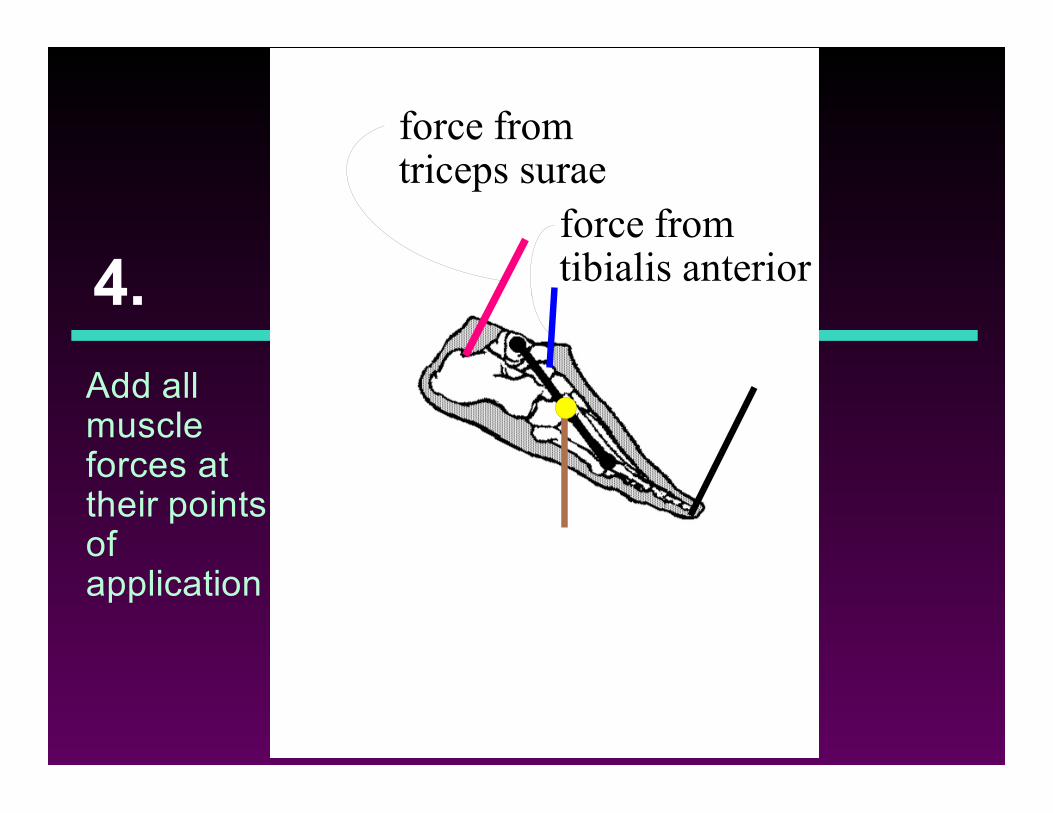
4.
Add allmuscleforces attheir pointsofapplication
force fromtriceps surae
force fromtibialis anterior
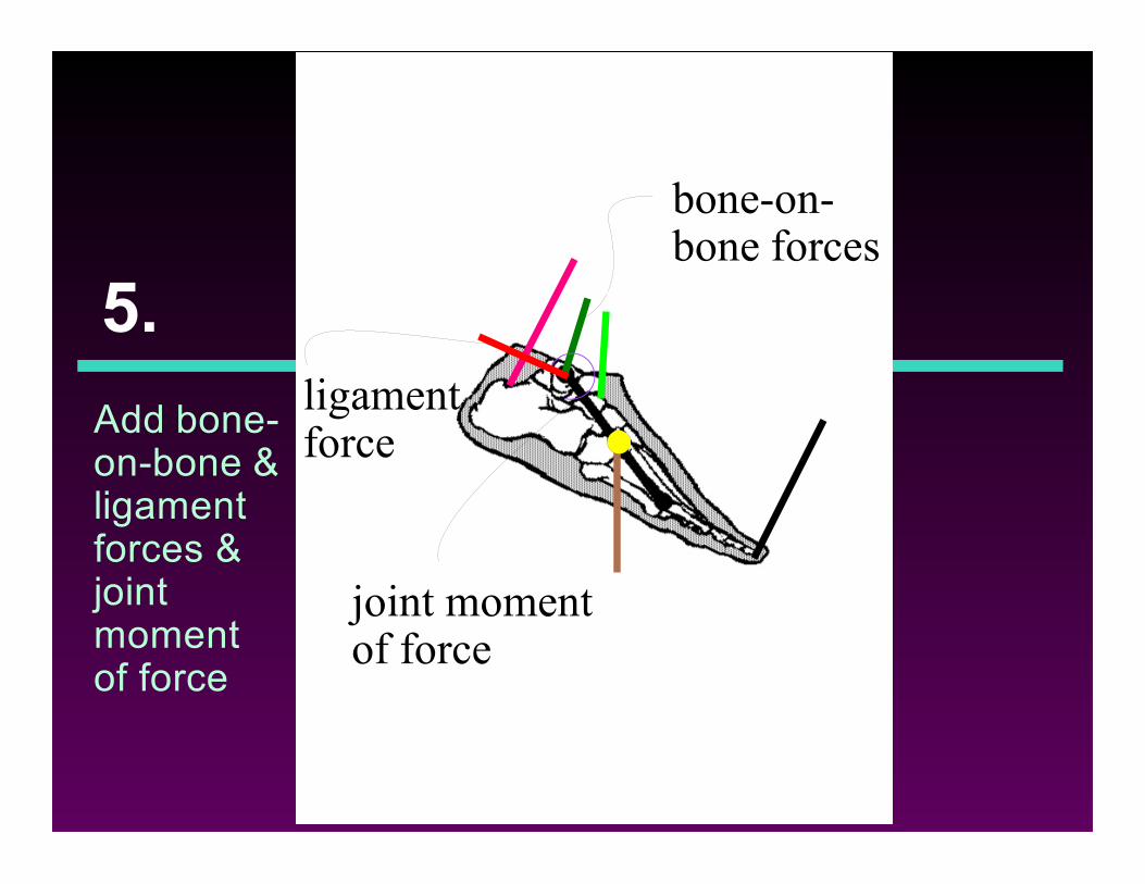
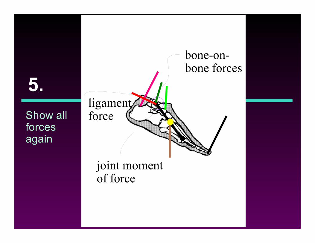
5.
Add bone-on-bone &ligamentforces &jointmomentof force
bone-on-bone forces
ligamentforce
joint momentof force
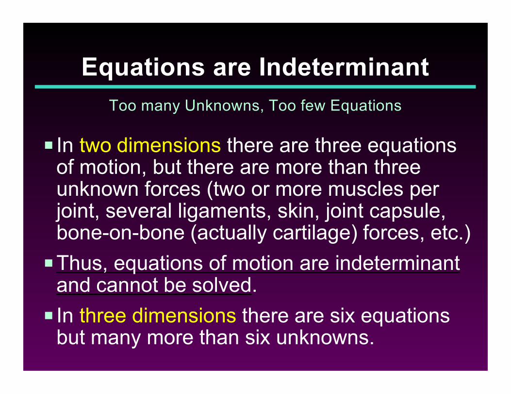
P In two dimensions there are three equationsof motion, but there are more than threeunknown forces (two or more muscles perjoint, several ligaments, skin, joint capsule,bone-on-bone (actually cartilage) forces, etc.)
PThus, equations of motion are indeterminantand cannot be solved.
P In three dimensions there are six equationsbut many more than six unknowns.
Equations are Indeterminant
Too many Unknowns, Too few Equations
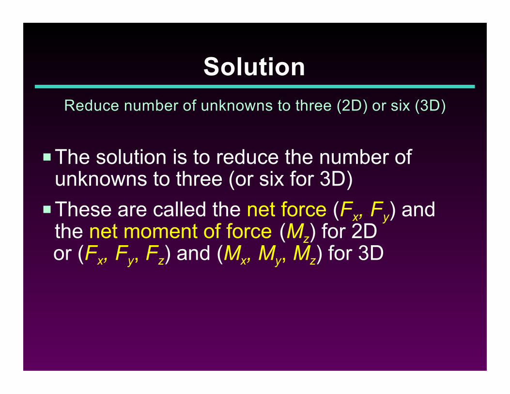
PThe solution is to reduce the number ofunknowns to three (or six for 3D)
PThese are called the net force (Fx, Fy) andthe net moment of force (Mz) for 2D
or (Fx, Fy, Fz) and (Mx, My, Mz) for 3D
Solution
Reduce number of unknowns to three (2D) or six (3D)
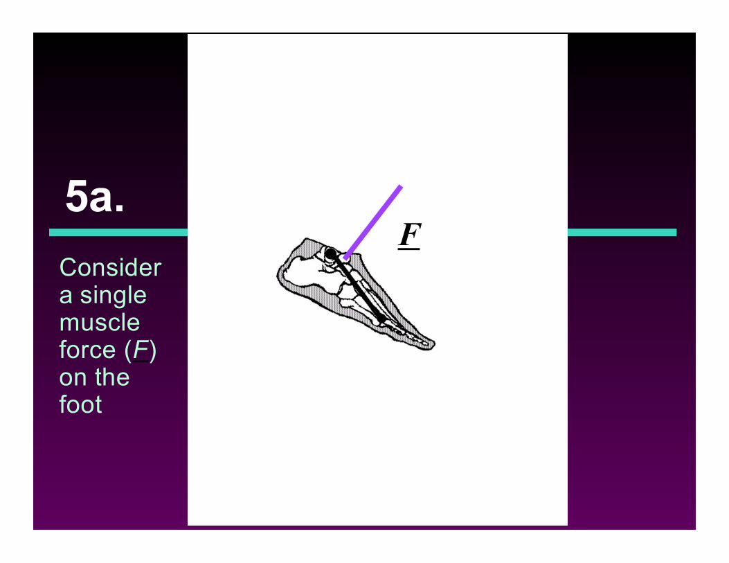
5a.
Considera singlemuscleforce (F)on thefoot
F
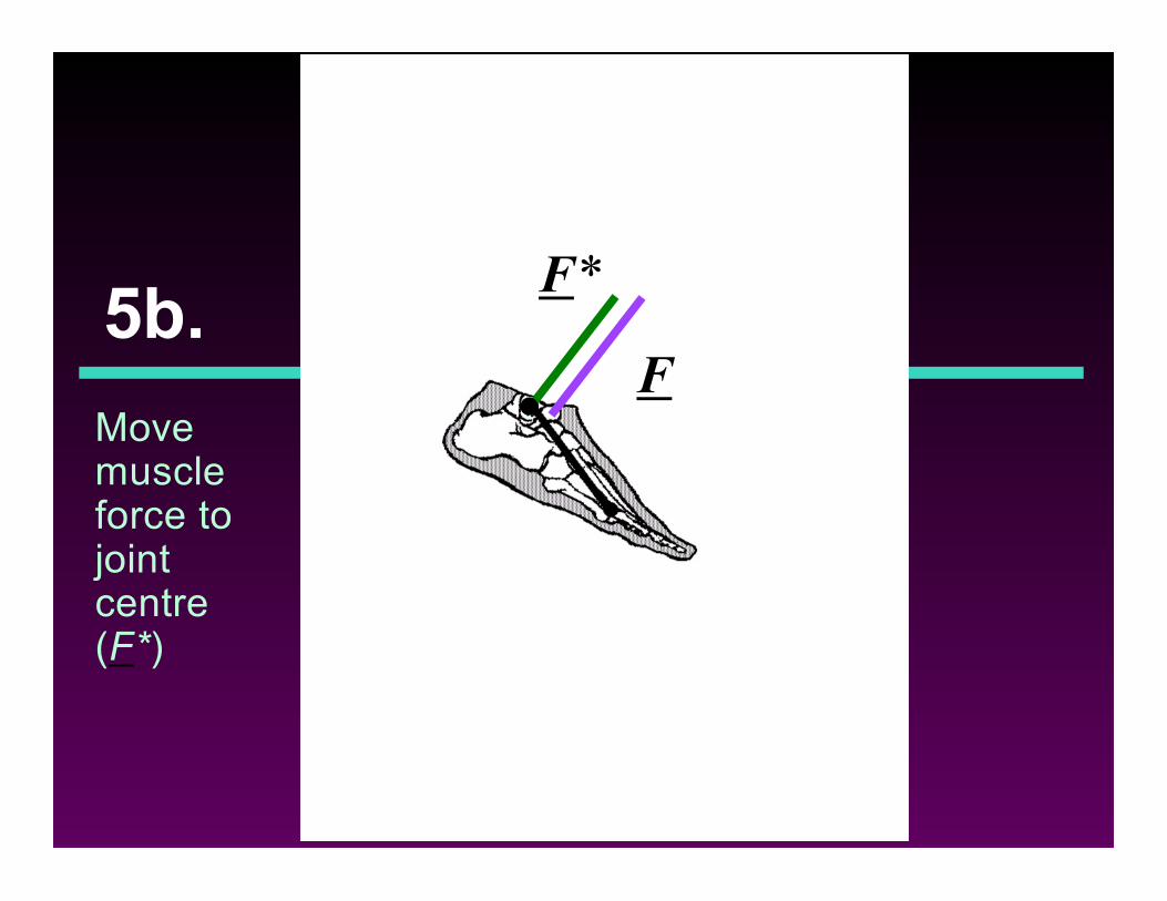
5b.
Movemuscleforce tojointcentre(F*)
F
F*
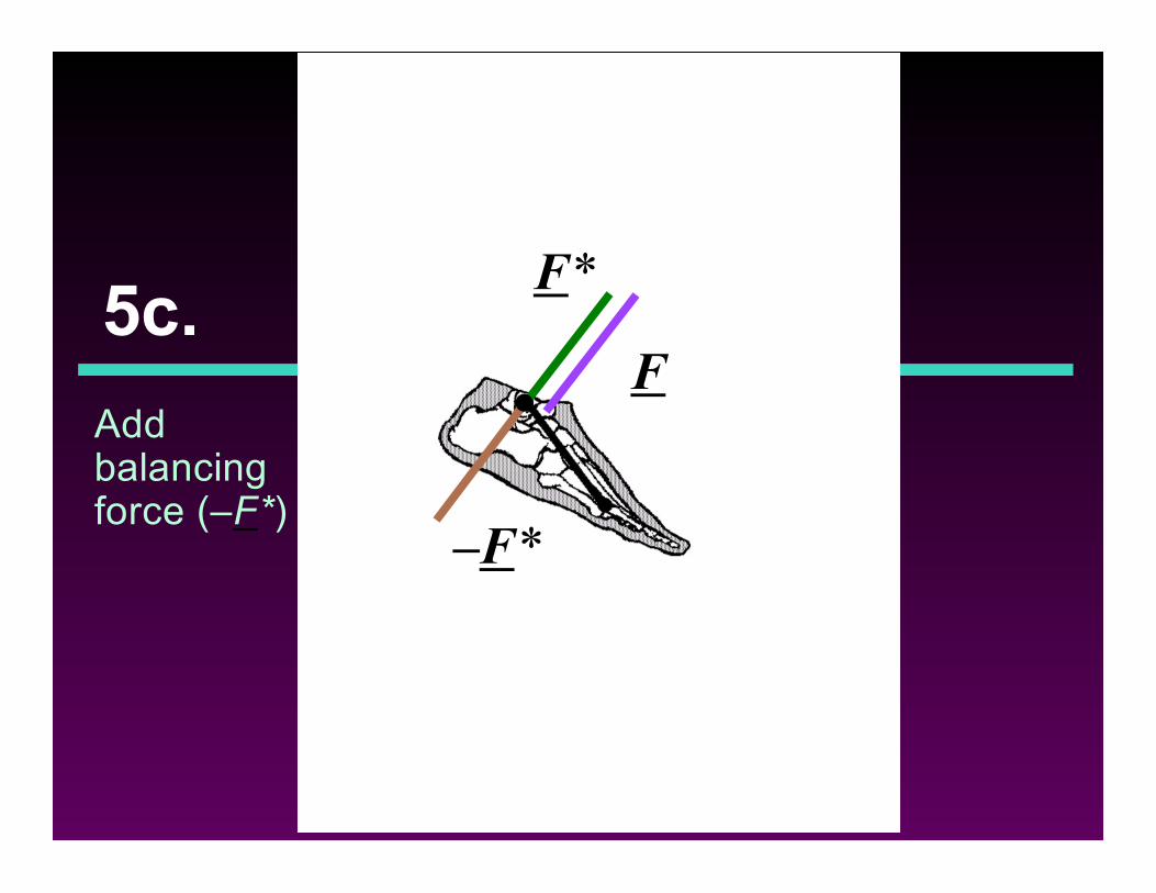
5c.
Addbalancingforce (–F*)
F
F*
–F*
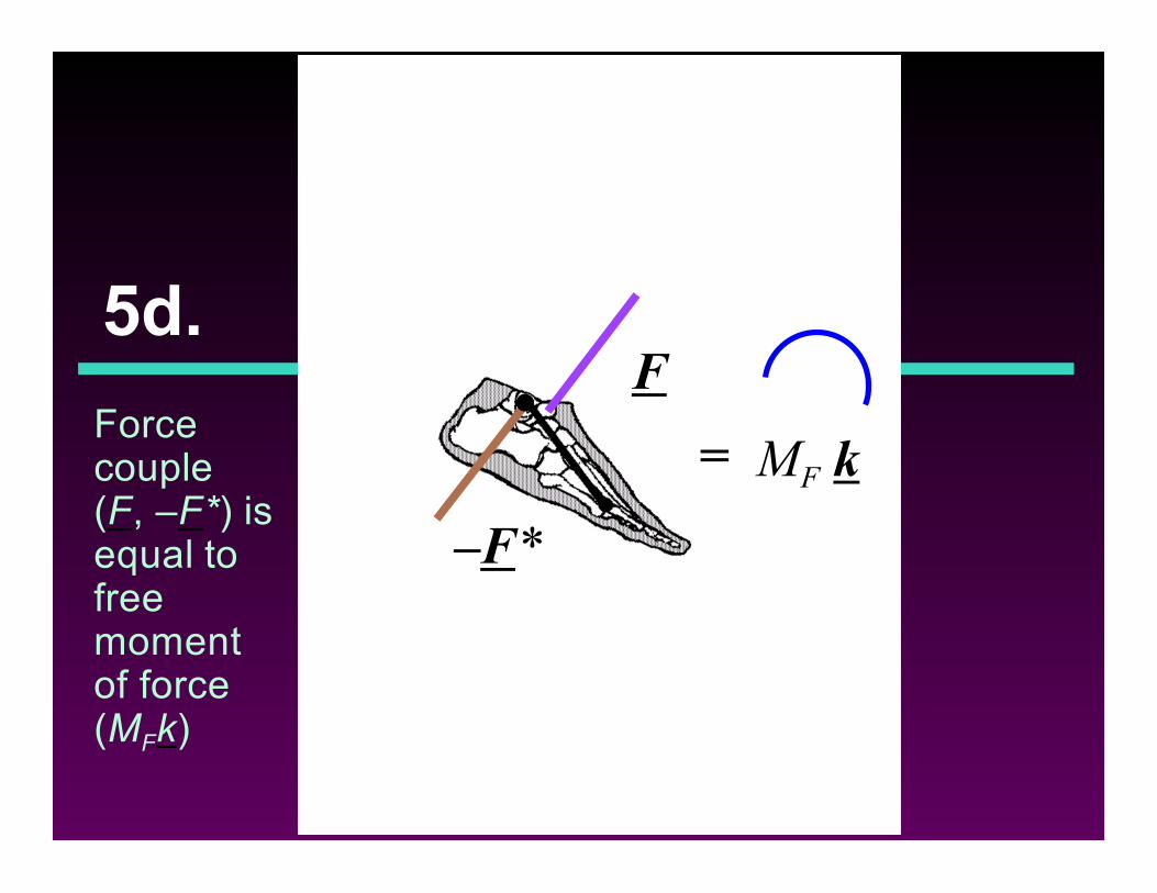
5d.
Forcecouple(F, –F*) isequal tofreemomentof force(MFk)
MF k
F
–F*
=
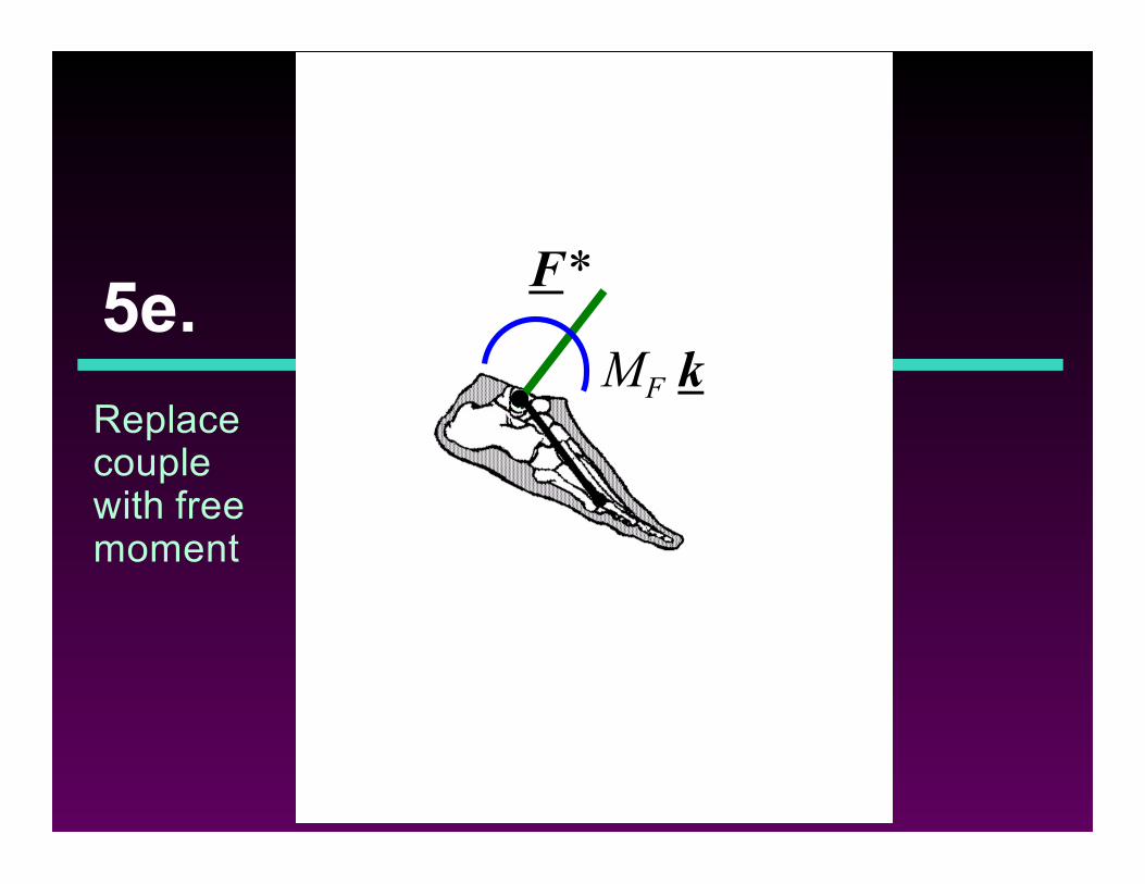
5e.
Replacecouplewith freemoment
F*
MF k
5.
Show allforcesagain
bone-on-bone forces
ligamentforce
joint momentof force
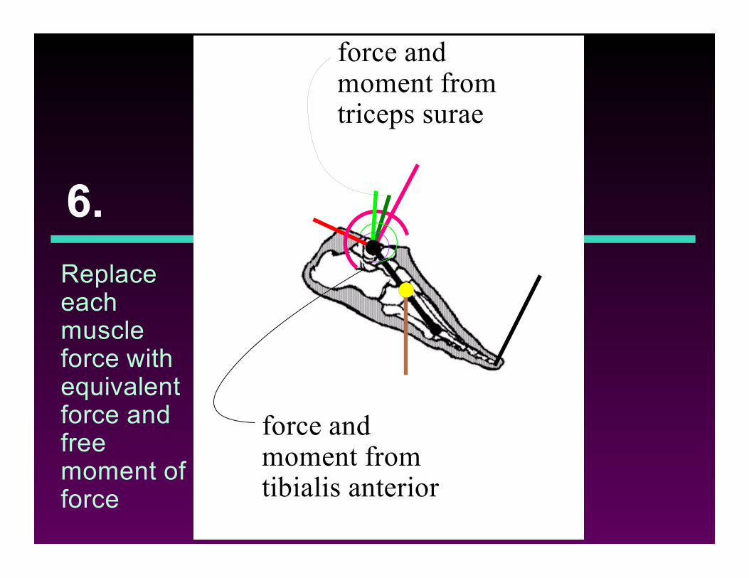
6.
Replaceeachmuscleforce withequivalentforce andfreemoment offorce
force andmoment fromtriceps surae
force andmoment fromtibialis anterior
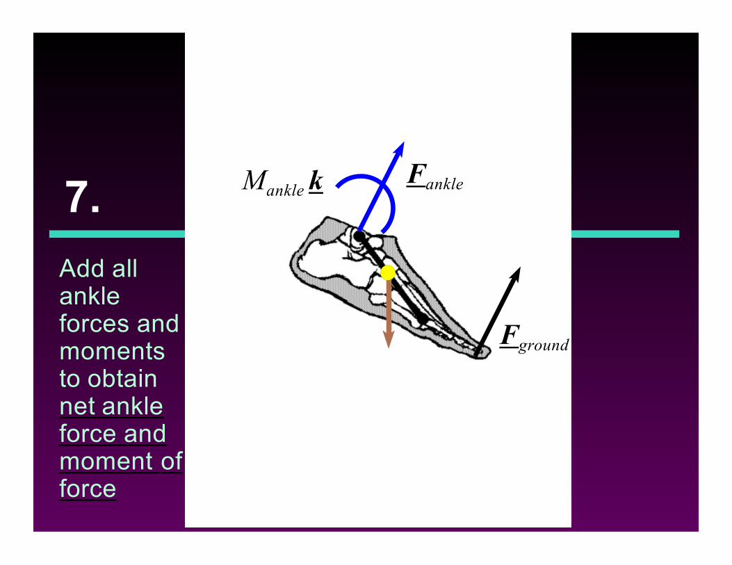
7.
Add allankleforces andmomentsto obtainnet ankleforce andmoment offorce
Mankle k Fankle
Fground
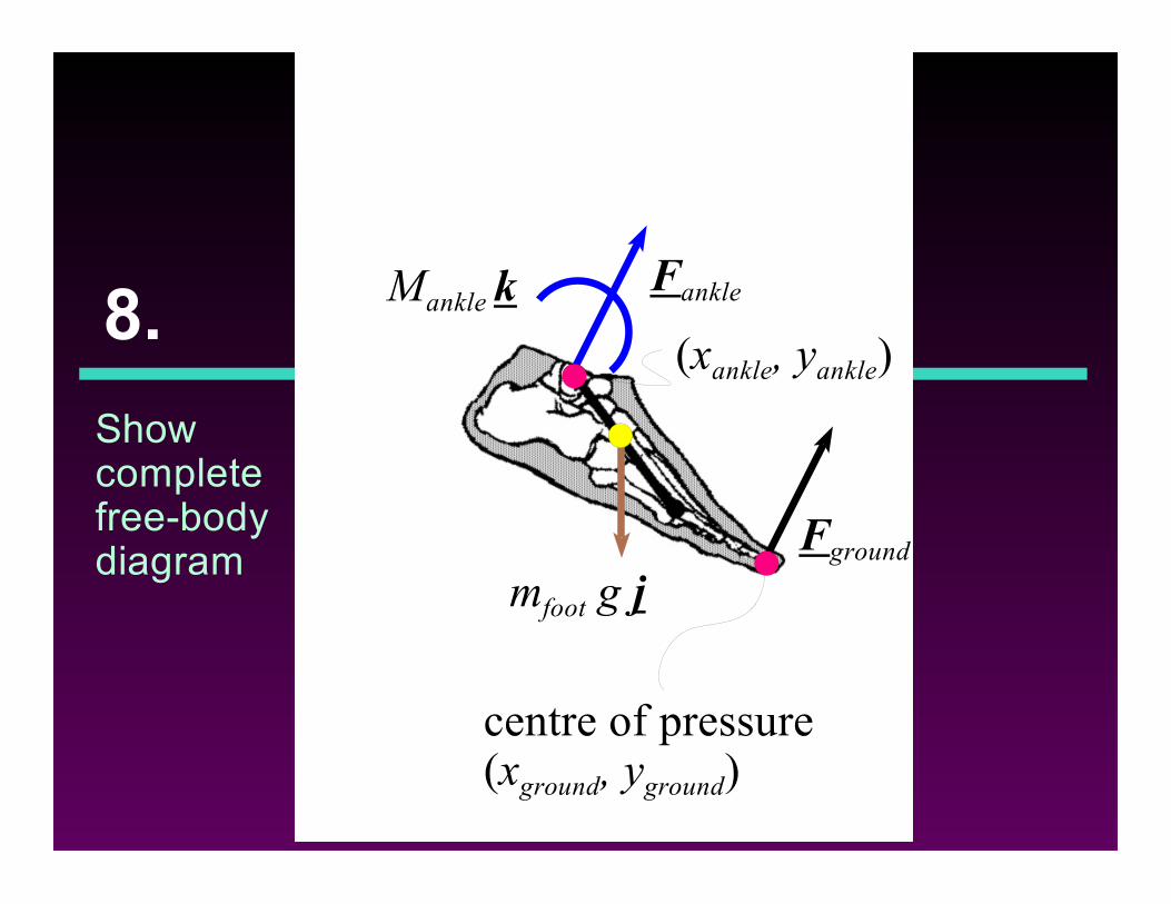
8.
Showcompletefree-bodydiagram
mfoot g jFground
FankleMankle k
centre of pressure(xground, yground)
(xankle, yankle)
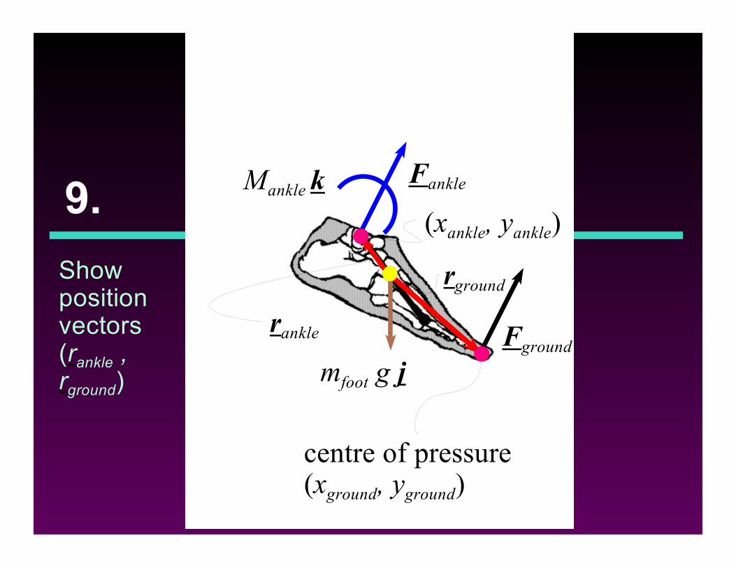
9.
Showpositionvectors(rankle ,rground)
mfoot g jFground
FankleMankle k
centre of pressure(xground, yground)
(xankle, yankle)
rground
rankle
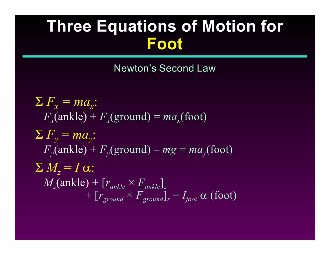
Ó Fx = max:Fx(ankle) + Fx(ground) = max(foot)
Ó Fy = may:Fy(ankle) + Fy(ground) – mg = may(foot)
Ó Mz = I a:Mz(ankle) + [rankle × Fankle]z
+ [rground × Fground]z = Ifoot a (foot)
Three Equations of Motion forFoot
Newton’s Second Law
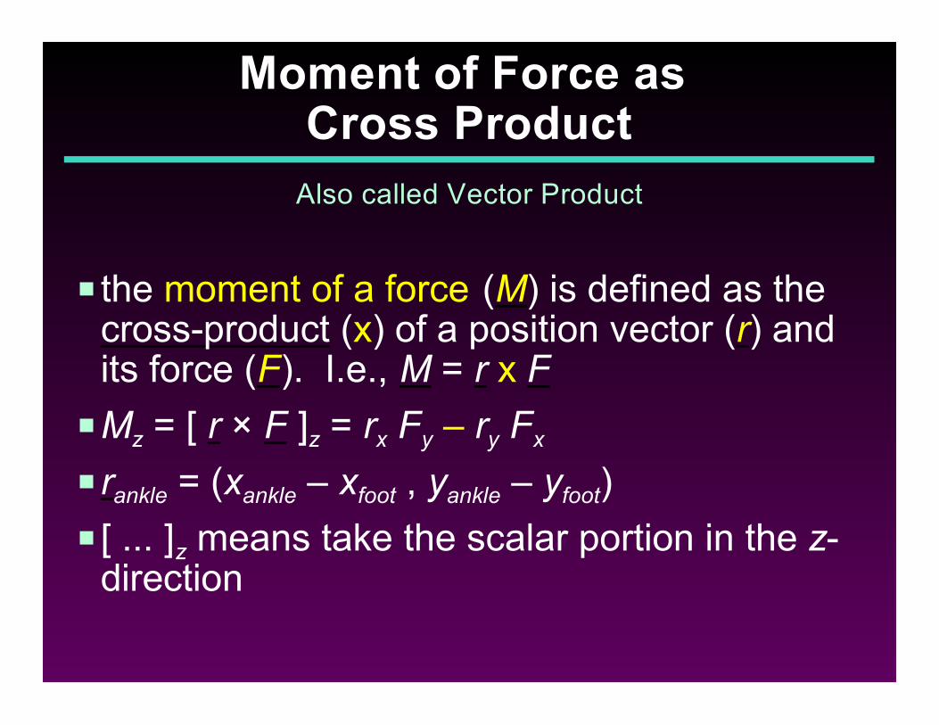
P the moment of a force (M) is defined as thecross-product (x) of a position vector (r) andits force (F). I.e., M = r x F
PMz = [ r × F ]z = rx Fy – ry Fx
P rankle = (xankle – xfoot , yankle – yfoot)
P [ ... ]z means take the scalar portion in the z-direction
Moment of Force as Cross Product
Also called Vector Product
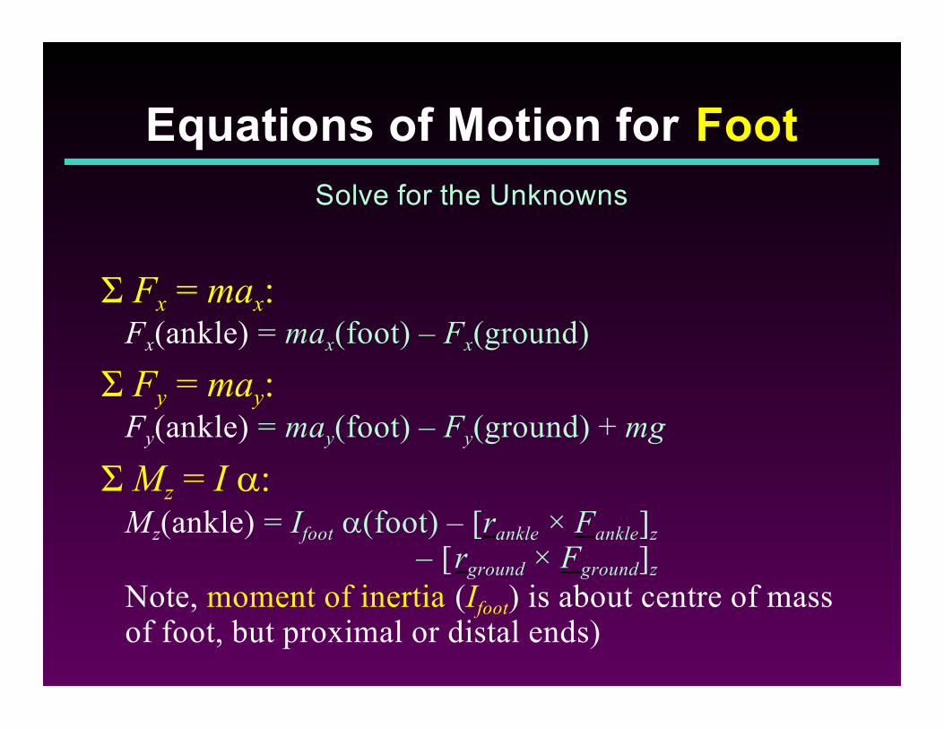
Ó Fx = max:Fx(ankle) = max(foot) – Fx(ground)
Ó Fy = may:Fy(ankle) = may(foot) – Fy(ground) + mg
Ó Mz = I a:Mz(ankle) = Ifoot a(foot) – [rankle × Fankle]z
– [rground × Fground]z Note, moment of inertia (Ifoot) is about centre of massof foot, but proximal or distal ends)
Equations of Motion for Foot
Solve for the Unknowns
PNet force and moment of force at proximalend of ankle causes reaction force andmoment of force at distal end of leg
PReactions are opposite in direction to actions
P I.e., reaction force = – action force reaction moment = – action moment
Apply Newton’s Third Law to Leg
Reaction = – Action
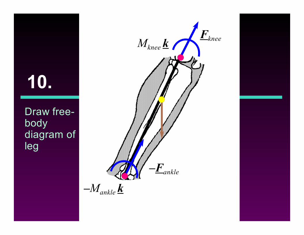
10.
Draw free-bodydiagram ofleg
FkneeMknee k
–Mankle k
–Fankle
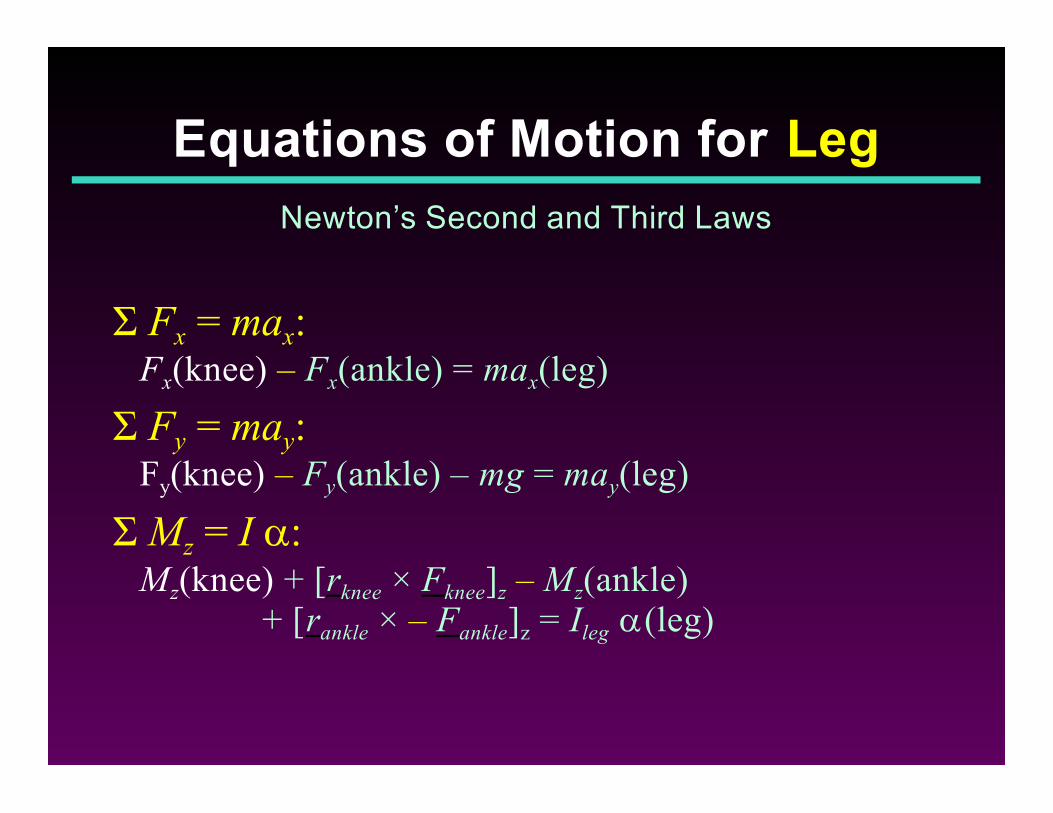
Ó Fx = max:Fx(knee) – Fx(ankle) = max(leg)
Ó Fy = may:Fy(knee) – Fy(ankle) – mg = may(leg)
Ó Mz = I a:Mz(knee) + [rknee × Fknee]z – Mz(ankle)
+ [rankle × – Fankle]z = Ileg a(leg)
Equations of Motion for Leg
Newton’s Second and Third Laws
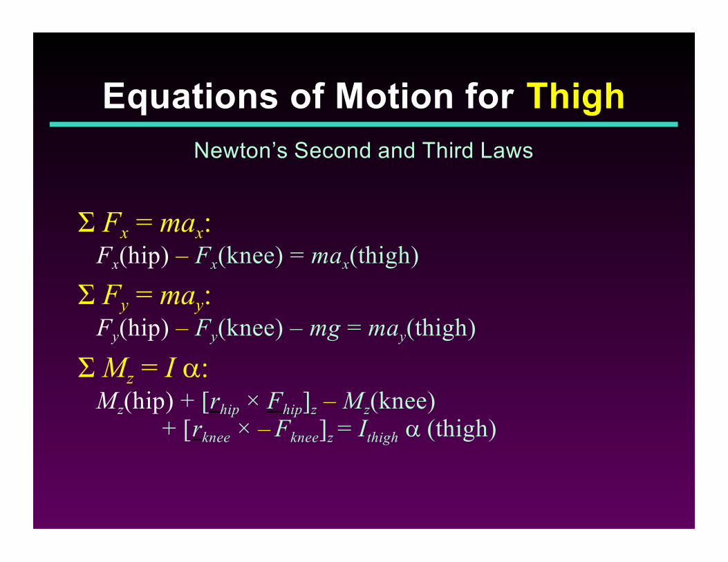
Ó Fx = max:Fx(hip) – Fx(knee) = max(thigh)
Ó Fy = may:Fy(hip) – Fy(knee) – mg = may(thigh)
Ó Mz = I a:Mz(hip) + [rhip × Fhip]z – Mz(knee)
+ [rknee × – Fknee]z = Ithigh a (thigh)
Equations of Motion for Thigh
Newton’s Second and Third Laws
PThese forces and moments aremathematical constructs NOT actual forcesand moments.
PThe actual forces inside joints and themoments across joints are higher because ofthe cocontractions of antagonists.
PFurthermore, there is no certain method toapportion the net forces and moments to theindividual anatomical structures.
Interpretation
Mathematical concepts not anatomical kinetics
Computerize the Process
E.g., 2D: Biomech Motion Analysis System;3D: Visual3D, Polygon, KinTools, KinTrak, Kwon3D
![[PPT]Biomechanical Analysis of the Soccer Kickhealth.uottawa.ca/biomech/courses/apa4311/kicking.ppt · Web view3D-Biomechanical Analysis of the Soccer Kick Introduction We chose to](https://img.pdfslide.us/doc/110x75/5ab836ae7f8b9ab62f8c5f10/pptbiomechanical-analysis-of-the-soccer-view3d-biomechanical-analysis-of-the-soccer.jpg)