Embed Size (px)
Citation preview

8/11/2019 Introduction to Finite Element Method_Chapt_02_Lect02
http://slidepdf.com/reader/full/introduction-to-finite-element-methodchapt02lect02 1/6
Lecture Notes: Introduction to Finite Element Method Chapter 2. Bar and Beam Elements
© 1998 Yijun Liu, University of Cincinnati 32
Example 2.1
Problem: Find the stresses in the two bar assembly which is
loaded with force P , and constrained at the two ends,
as shown in the figure.
Solution: Use two 1-D bar elements.
Element 1,
u u
EA
L
1 2
1
2 1 1
1 1k =
−−
Element 2,
u u
EA
L
2 3
2
1 1
1 1k =
−−
Imagine a frictionless pin at node 2, which connects the twoelements. We can assemble the global FE equation as follows,
EA
L
u
u
u
F
F
F
2 2 0
2 3 1
0 1 1
1
2
3
1
2
3
−− −
−
=
1
2 A,E
2 3
,E 1 2
8/11/2019 Introduction to Finite Element Method_Chapt_02_Lect02
http://slidepdf.com/reader/full/introduction-to-finite-element-methodchapt02lect02 2/6
Lecture Notes: Introduction to Finite Element Method Chapter 2. Bar and Beam Elements
© 1998 Yijun Liu, University of Cincinnati 33
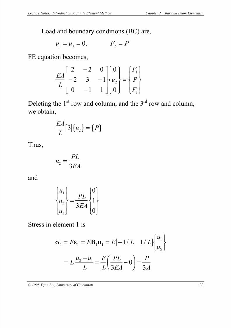
Load and boundary conditions (BC) are,
u u F P 1 3 2
0= = =,
FE equation becomes,
EA
Lu
F
P
F
2 2 0
2 3 1
0 1 1
0
0
2
1
3
−− −
−
=
Deleting the 1st row and column, and the 3rd row and column,
we obtain,
[ ]{ } { } EA
Lu P 3
2 =
Thus,
u PL
EA2
3=
and
u
u
u
PL
EA
1
2
3
3
0
1
0
=
Stress in element 1 is
[ ]σ ε1 1 1 1
1
2
2 1
1 1
30
3
= = = −
= −
= −
=
E E E L Lu
u
E u u
L
E
L
PL
EA
P
A
B u / /

8/11/2019 Introduction to Finite Element Method_Chapt_02_Lect02
http://slidepdf.com/reader/full/introduction-to-finite-element-methodchapt02lect02 3/6
Lecture Notes: Introduction to Finite Element Method Chapter 2. Bar and Beam Elements
© 1998 Yijun Liu, University of Cincinnati 34
Similarly, stress in element 2 is
[ ]σ ε2 2 2 2
2
3
3 2
1 1
03 3
= = = −
=
−= −
= −
E E E L Lu
u
E u u
L
E
L
PL
EA
P
A
B u / /
which indicates that bar 2 is in compression.
Check the results!
Notes:
• In this case, the calculated stresses in elements 1 and 2
are exact within the linear theory for 1-D bar structures.
It will not help if we further divide element 1 or 2 into
smaller finite elements.
• For tapered bars, averaged values of the cross-sectionalareas should be used for the elements.
• We need to find the displacements first in order to find
the stresses, since we are using the displacement based
FEM .

8/11/2019 Introduction to Finite Element Method_Chapt_02_Lect02
http://slidepdf.com/reader/full/introduction-to-finite-element-methodchapt02lect02 4/6
Lecture Notes: Introduction to Finite Element Method Chapter 2. Bar and Beam Elements
© 1998 Yijun Liu, University of Cincinnati 35
Example 2.2
Problem: Determine the support reaction forces at the two ends
of the bar shown above, given the following,
P E
A L =
= × = ×
= =
6 0 10 2 0 10
250 150
4 4
2
. , . ,
,
N N / mm
mm mm, 1.2 mm
2
∆
Solution:
We first check to see if or not the contact of the bar with
the wall on the right will occur. To do this, we imagine the wallon the right is removed and calculate the displacement at the
right end,
∆ ∆0
4
4
6 0 10 150
2 0 10 25018 12= = ×
× = > = PL
EA
( . )( )
( . )( ). .mm mm
Thus, contact occurs.
The global FE equation is found to be,
EA
L
u
u
u
F
F
F
1 1 0
1 2 1
0 1 1
1
2
3
1
2
3
−− −
−
=
1
,E
2 3
1 2
∆

8/11/2019 Introduction to Finite Element Method_Chapt_02_Lect02
http://slidepdf.com/reader/full/introduction-to-finite-element-methodchapt02lect02 5/6
Lecture Notes: Introduction to Finite Element Method Chapter 2. Bar and Beam Elements
© 1998 Yijun Liu, University of Cincinnati 36
The load and boundary conditions are,
F P
u u
2
4
1 3
6 0 10
0 12
= = ×
= = =
.
, .
N
mm∆FE equation becomes,
EA
Lu
F
P
F
1 1 0
1 2 1
0 1 1
0
2
1
3
−− −
−
=
∆
The 2nd equation gives,
[ ] { } EA
L
u P 2 1
2−
=∆
that is,
[ ]{ } EA
Lu P
EA
L2
2 = +
∆
Solving this, we obtain
u PL
EA2
1
215= +
=∆ . mm
and
u
u
u
1
2
3
0
15
12
=
.
.
( )mm
8/11/2019 Introduction to Finite Element Method_Chapt_02_Lect02
http://slidepdf.com/reader/full/introduction-to-finite-element-methodchapt02lect02 6/6
Lecture Notes: Introduction to Finite Element Method Chapter 2. Bar and Beam Elements
© 1998 Yijun Liu, University of Cincinnati 37
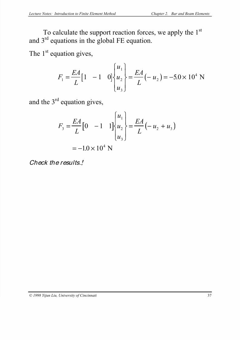
To calculate the support reaction forces, we apply the 1st
and 3rd equations in the global FE equation.
The 1st equation gives,
[ ] ( ) F EA
L
u
u
u
EA
Lu
1
1
2
3
2
41 1 0 50 10= −
= − = − ×. N
and the 3rd equation gives,
[ ] ( ) F EA
L
uu
u
EA
Lu u
3
1
2
3
2 3
4
0 1 1
10 10
= −
= − +
= − ×. N
Check the results.!