Embed Size (px)
Citation preview

The Gibson Varitone - Where’s the Disconnect? Chris Wargo 12-28-2010
Introduction The purpose of this paper is to ask (and hopefully answer) the question “Should I bother disconnecting my Varitone in my Gibson guitar?” Conventional wisdoms (aka internet fora) tell us that Varitones are evil tone-suckers that can’t be bypassed. They should be removed from a guitar, carried across the Misty Mountains and thrown into the fires of Mount Doom in order to prevent the evil from ever infecting the guitar again. What the Varitone does when it is actually used isn’t much of a controversial subject. Its effects are obvious. Love it or hate it, it does what it does and there isn’t much controversy about this. The controversy comes when the subject of bypassing the Varitone is discussed. As a fan of vintage ES-345’s I see a large numbers of these guitars on the market with disconnected, or even fully gutted Varitones. I liken these two operations to vasectomy and castration, and the question needs to be asked if this is really necessary. When the subject is discussed on the internet, the evidence in the debate usually consists of someone’s claims that they gutted their Varitone and their guitar tone went from a banjo stuffed with a wet blanket to a shimmering brass bell being hit with a chambered mahogany mallet. I have a couple of issues with this evidence. First off, I don’t know these posters. Enough said. Secondly, the posters are probably a human. I am a human, and I have spent a lot time in recording studios, both behind and in front of the board. I remember one time where I set up an outboard compressor with a mild ratio for a mix bus. With the band listening, I switched the compression in and out from the mixing desk for everyone to evaluate. We would talk about how the cymbals became a little too splashy with the comp, but the vocals got that forward spatial extension that we all liked. The bass was a little pumpy, but the rhythm section became a little better glued with the comp. After all this cork sniffing was over and we decided to go with the compression, I looked down at the compressor itself and noticed it was in bypass mode. Often times, when subtle differences are being evaluated, we hear what we want to hear. This was with direct A/B switching. I trust human perception a whole lot less when an hour or more time elapses between A and B, like the time it takes to disconnect a Varitone. I trust memory even less, so the fact that you’ve been playing that guitar for 40 years doesn’t count much in my book either. I’ve made guitars sound better by simply not playing them for a while (“damn that old Strat sounds better than I remember…”) Sometimes, sound files are provided of before and after the operation. This doesn’t work for me again, because like above, I don’t know the poster. I don’t know this person’s motivations or abilities. I’ve heard sound files where the “before” file sounded like a 16K neck humbucker with the tone knob rolled all the way down being played through an 18” bass reflex cabinet, and the “after” file sounded like a Strat being played through the “clean” setting on a Scholz Rockman. I don’t know if the microphone got kicked in between takes, if the cat turned his treble up, if the first recording was made in 1965 and the second in 2010, etc. At the end of this diatribe, I’m going to present my own sound files, but for all you know, I’m full of Shinola too. So to add to my argument, I am going to discuss the actual Varitone circuit. My goal is to present a slightly technical analysis that lies somewhere in between an analysis based on second order differential equations, and “dude, look at all that stuff, it just gotta kill your tone”.

The Varitone Circuit The schematic for the Gibson Varitone is available for download on the internet at multiple sites, gibson.com included. I’ve attached an excerpt of an ES-345 schematic below for convenience. I removed the bridge pickup, pickup selector switch, and output jack for simplicity. This is what the circuit looks like if only one pickup is selected. Other mono Varitone schematics are also available on the web.
to output
Fig 1 – Gibson Varitone schematic for an ES-345. Edited to show mono operation. Somebody who doesn’t know electronics in depth might look at this schematic and see a lot of stuff there that doesn’t need to be there, especially if the player doesn’t plan on actually using the unit. I respect this skepticism, and I myself often subscribe to the “less-is-more” philosophy for audio electronics design. But let’s start looking at the schematic in simplified format as a function of which setting is selected. We’ll start by looking at position 2. Right off the bat, let’s remove the standard volume and tone controls and focus on the Varitone circuit. When switched to position 2, we can ignore all the circuitry from the other positions, since even the anti-Varitone coalitions should agree that any impact they have on the sound can be ignored compared to the major impact from the engaged position. This leaves us with the following schematic:
Figure 2 – Gibson Varitone with position 2 engaged. Volume and tone pots removed for clarity.
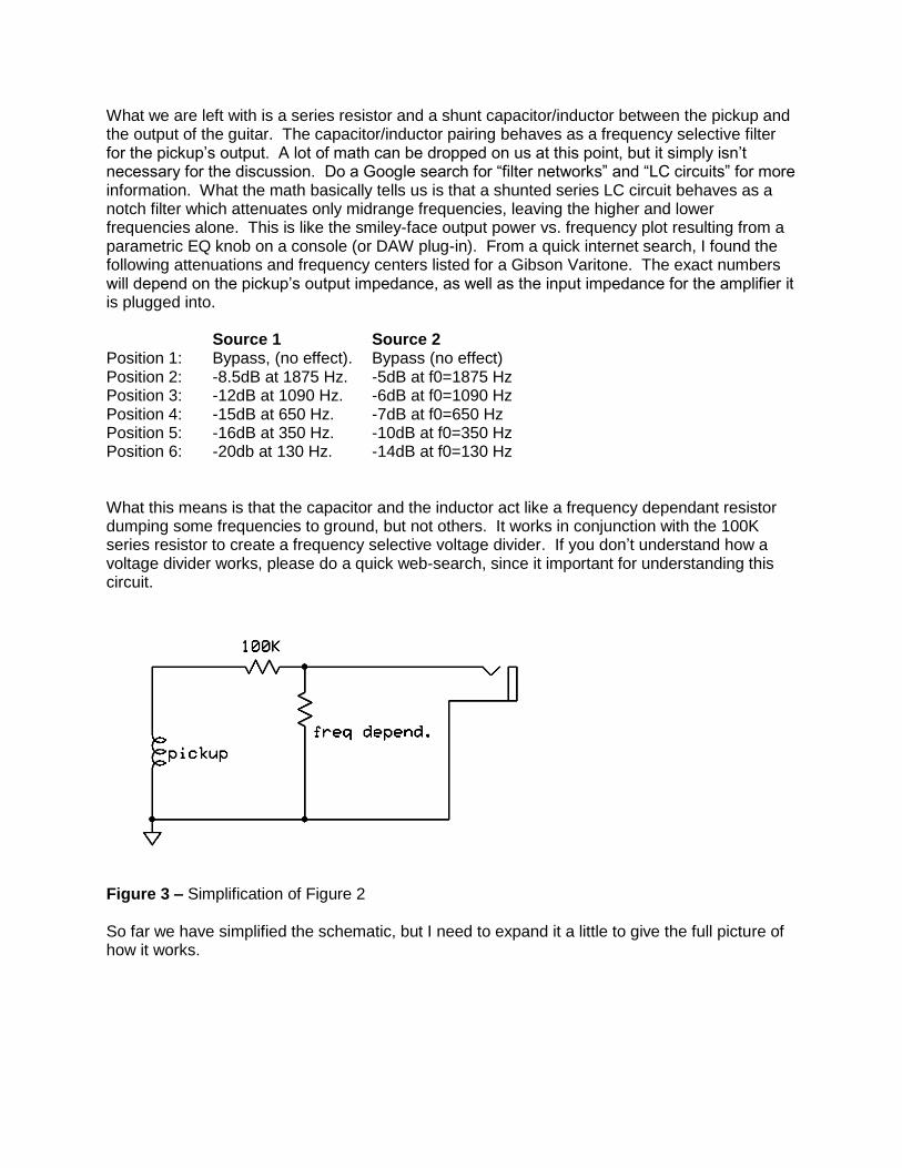
What we are left with is a series resistor and a shunt capacitor/inductor between the pickup and the output of the guitar. The capacitor/inductor pairing behaves as a frequency selective filter for the pickup’s output. A lot of math can be dropped on us at this point, but it simply isn’t necessary for the discussion. Do a Google search for “filter networks” and “LC circuits” for more information. What the math basically tells us is that a shunted series LC circuit behaves as a notch filter which attenuates only midrange frequencies, leaving the higher and lower frequencies alone. This is like the smiley-face output power vs. frequency plot resulting from a parametric EQ knob on a console (or DAW plug-in). From a quick internet search, I found the following attenuations and frequency centers listed for a Gibson Varitone. The exact numbers will depend on the pickup’s output impedance, as well as the input impedance for the amplifier it is plugged into.
Source 1 Source 2 Position 1: Bypass, (no effect). Bypass (no effect) Position 2: -8.5dB at 1875 Hz. -5dB at f0=1875 Hz Position 3: -12dB at 1090 Hz. -6dB at f0=1090 Hz Position 4: -15dB at 650 Hz. -7dB at f0=650 Hz Position 5: -16dB at 350 Hz. -10dB at f0=350 Hz Position 6: -20db at 130 Hz. -14dB at f0=130 Hz What this means is that the capacitor and the inductor act like a frequency dependant resistor dumping some frequencies to ground, but not others. It works in conjunction with the 100K series resistor to create a frequency selective voltage divider. If you don’t understand how a voltage divider works, please do a quick web-search, since it important for understanding this circuit.
Figure 3 – Simplification of Figure 2 So far we have simplified the schematic, but I need to expand it a little to give the full picture of how it works.
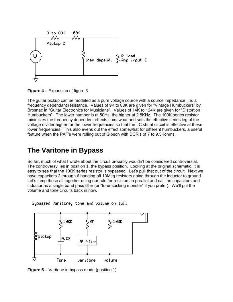
Figure 4 – Expansion of figure 3 The guitar pickup can be modeled as a pure voltage source with a source impedance, i.e. a frequency dependant resistance. Values of 9K to 83K are given for “Vintage Humbuckers” by Brosnac in “Guitar Electronics for Musicians”. Values of 14K to 124K are given for “Distortion Humbuckers”. The lower number is at 50Hz, the higher at 2.5KHz. The 100K series resistor minimizes the frequency dependent effects somewhat and sets the effective series leg of the voltage divider higher for the lower frequencies so that the LC shunt circuit is effective at these lower frequencies. This also evens out the effect somewhat for different humbuckers, a useful feature when the PAF’s were rolling out of Gibson with DCR’s of 7 to 9.5Kohms.
The Varitone in Bypass So far, much of what I wrote about the circuit probably wouldn’t be considered controversial. The controversy lies in position 1, the bypass position. Looking at the original schematic, it is easy to see that the 100K series resistor is bypassed. Let’s pull that out of the circuit. Next we have capacitors 2 through 6 hanging off 10Meg resistors going through the inductor to ground. Let’s lump these all together using our rule for resistors in parallel and call the capacitors and inductor as a single band pass filter (or “tone-sucking monster” if you prefer). We’ll put the volume and tone circuits back in now.
Figure 5 – Varitone in bypass mode (position 1)

This leaves us with the schematic depicted above. Note that the “tone-sucking monster” is being blocked by a very high net resistor value, 2M. The other “tone-sucking monster”, your tone pot (ironic isn’t it) is only being blocked by a 500K resistor, which is your tone pot turned all the way up. Let’s also note that the tone pot circuit is essentially a high pass filter, working only on the high frequencies. The Varitone is a band pass filter working on mid and low frequencies. Since the series resistor in the Varitone circuit has been removed, the output impedance of the pickup is the only thing left to make the voltage divider with the LC circuit. You have a very strong shunt resistor blocking the band pass filter of the Varitone, and a weakened series resistor that is particularly weak at the frequencies that the Varitone is designed to filter. On the other hand, you have a weaker shunt resistor on the tone capacitor (HP filter) and a stronger series resistor at the frequencies that the tone cap works at. In the case of the Varitone in bypass , the capacitors are summed to give a single capacitor of 0.264 microfarads, almost the same as position 6 by itself. This means that the Varitone is set to filter out low frequencies if anything can get by it. In schematic form:
Figures 6 and 7 – Varitone vs tone circuits. It should also be noted that the 500K pot is the value used in vintage Gibsons. Gibsons from the 70’s and 80’s used 300K and 100K pots at times, further adding to the “tone” knob suckery. Looking at the schematics above, which do you think has a greater effect on your tone?

As a side note, you might be wondering at this point why the 10M resistors were even added to the circuit if they don’t have an effect on the sound. They are used so that the Varitone doesn’t pop when switched.
Spice Modeling of Bypass vs. True Bypass
Spice models were made up of the Varitone circuit, position 1 and a true bypass setup with the Varitone removed from the guitar completely (thanks to Gus Smalley for the simulations). The results confirm that the Varitone in position 1 does not cause a change in frequency response compared to the Varitone removed from the circuit entirely. In fact, the model suggests that there is actually a little more HF extension in Position1 compared to complete removal, but within the limits of accuracy of any simplified mathematical model, we might conclude that the results are equivalent.
Figure 8 - Spice model of the Varitone circuit
Figures 9 and 10 - Frequency and phase response of position 1 and true bypass

Figure 11 - Frequency and phase response of position 4 on the Varitone
Figure 11 above shows a model of the typical scooped response when the Varitone is engaged. As the knob is turned up, the frequency center is lowered, until position 6 is reached and the frequency center is so low as to effectively make a low cut response at the guitar’s output.
Varitone Issues that Aren’t Varitone Issues
I once spoke with a fellow who hated Varitones and insisted that his sound improved 100% when he had his Varitone removed from his ES-345. He had always left the Varitone in bypass, but felt that his tone was always a little wonky compared to his ES-335. After talking to him more, it turns out that he was one of those atypical players that use both pickups together more than 90% of the time. He also used a summing cable to play the guitar through a standard mono amplifier (see below). Since the ES-345 has the pickups out of phase with each other, what he was hearing was the difference between the pickups, rather than the summation of them. When the 345 was redone to 335 specs, the pickups were put back in phase by flipping one of the magnets. No more wonkiness. And I feel obliged to advise, please don’t do this to a PAF, or even a nice clean Patent number pickup. In addition to the phase issue mentioned above, there is one more issue with a Varitone equipped ES-345. It’s a stereo issue. Think of an ES-345 (or any other stereo guitar) as two separate guitars, one with a neck pickup and one with a bridge pickup. If these two guitars are summed together with a simple Y cable, then the controls of one guitar will affect the controls of the other guitar when both guitars are switched in. The same thing would happen if you played a strat and a les Paul together into a single amp with an A-B-AB box. If both guitars are switched on, the Les Paul tone and volume will control the output of the Strat. Also, both sets of volume and tone controls will load both guitars, so in this case, it would be like playing your Strat with 166K pots on the volume and tone (or 250K with two Gibsons). This is no longer a problem when only one of the guitars is switched to the amp (A or B, not AB). An ES-345 is wired with the pickup selector before the volume/tone/Varitone controls. With a summing cable, it would be the equivalent of having both guitars turned on all the time with the A-B-AB switcher. You can still select pickups, but you lose independent volume and tone controls and your pots become 250K pots, essentially. So what is the best way to use a stereo guitar with rewiring it? I’ll discuss this at the end of the document, but for now, let’s get back to Varitones.

Varitones That Do Affect your Tone in Bypass I do own a guitar with a Varitone that can’t be bypassed properly, and that’s my ’64 Epiphone EAP-7. This guitar has individual switches instead of a single rotary switch. Notice that there isn’t a single series resistor, but rather individual series resistors that sum up the higher the switch number you use. This design was done so that the gain loss from the Varitone is evened out between settings.
Figure 12 – Varitone on a ’64 Epiphone EA7-P (made by Gibson).
Figure 13 – Switch 3 active
Figure 14 – Bypass
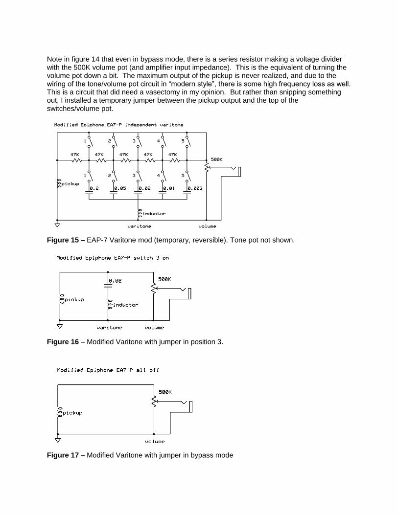
Note in figure 14 that even in bypass mode, there is a series resistor making a voltage divider with the 500K volume pot (and amplifier input impedance). This is the equivalent of turning the volume pot down a bit. The maximum output of the pickup is never realized, and due to the wiring of the tone/volume pot circuit in “modern style”, there is some high frequency loss as well. This is a circuit that did need a vasectomy in my opinion. But rather than snipping something out, I installed a temporary jumper between the pickup output and the top of the switches/volume pot.
Figure 15 – EAP-7 Varitone mod (temporary, reversible). Tone pot not shown.
Figure 16 – Modified Varitone with jumper in position 3.
Figure 17 – Modified Varitone with jumper in bypass mode
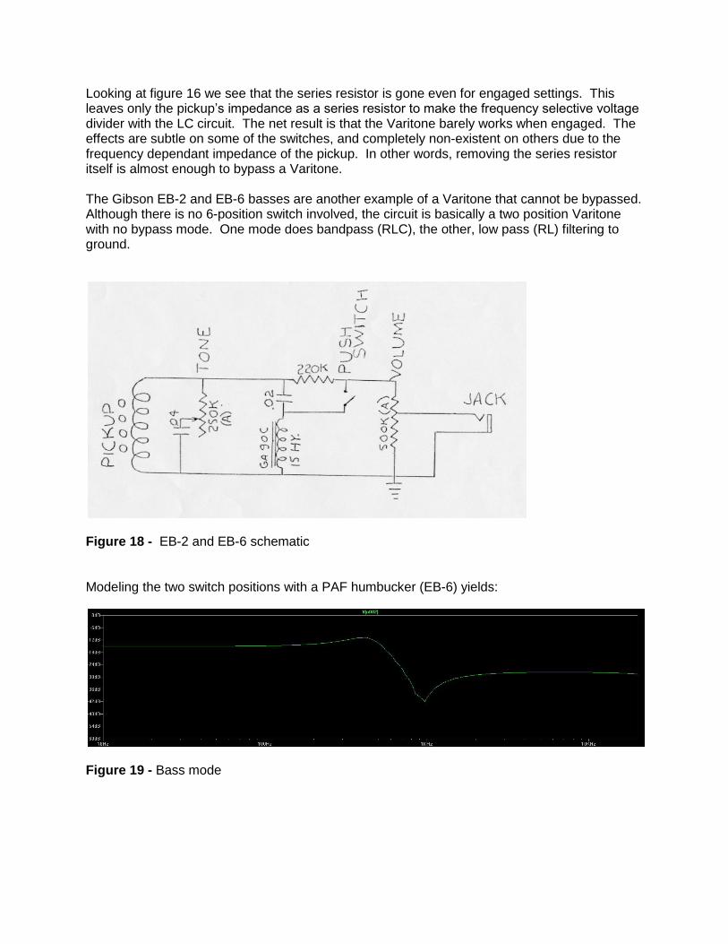
Looking at figure 16 we see that the series resistor is gone even for engaged settings. This leaves only the pickup’s impedance as a series resistor to make the frequency selective voltage divider with the LC circuit. The net result is that the Varitone barely works when engaged. The effects are subtle on some of the switches, and completely non-existent on others due to the frequency dependant impedance of the pickup. In other words, removing the series resistor itself is almost enough to bypass a Varitone. The Gibson EB-2 and EB-6 basses are another example of a Varitone that cannot be bypassed. Although there is no 6-position switch involved, the circuit is basically a two position Varitone with no bypass mode. One mode does bandpass (RLC), the other, low pass (RL) filtering to ground.
Figure 18 - EB-2 and EB-6 schematic Modeling the two switch positions with a PAF humbucker (EB-6) yields:
Figure 19 - Bass mode

Figure 20 - Baritone mode I’ve also heard complaints about the Varitone in the Gibson L6S (usually form people who don’t own one). That’s a simple one to discuss. That isn’t a Varitone. It’s a pickup selector switch that gives series/parallel and in/out phase settings as well. Beware, not all 5 or 6 position switches with chicken-heads are Varitones.
The Ins and Outs of Using a Stereo Guitar
OK, fine, so maybe I’ve convinced you not to rip out your Varitone, but admittedly, there are some issues with using a stereo guitar. Let’s discuss what your options are, and what the benefits and drawbacks of each are.
Method 1: Use it stereo, man! Go down to Radioshack, buy a ¼” stereo Y-cable, and plug it into two amps (or a single stereo amp). Until you have tried this, you’re missing something truly spectacular. It’s fullness like you’ve never heard. Run one pickup clean, one dirty. Run them both full-range, or tune the neck input for bass and the bridge input for treble. Run two effect chains, chorus on one, delay on the other, stereo reverb on both, etc. I promise you, you won’t leave your house for a week. When you do, bring two 40lb amps to the gig instead of one 80lb amp. Your ears, your audience, and your back will thank you (but the sound man might think you’re a diva). Pots: Normal values Phase when using both pickups: Depends on the amps (some invert, some don’t) Controls: Neck and bridge controls are isolated from each other Method 2: Use a stereo Y cable with a two-channel amp. You’ll lose the juicy spaciousness, but the guitar will pretty much behave like a regular guitar (ala ES-335 or Les Paul). The only difference is that each pickup will have its own gain and tone stack (probably a good thing). In my opinion, this is better than normal ES-335 wiring and you don’t need to perform surgery on your guitar to get it. The only downside is that you’re not using a standard cord. Note, a single channel amp with two inputs won’t have the same effect. That configuration is equivalent to method 4. Pots: Normal values Phase when using both pickups: Depends on the amp (some channels invert, some don’t) Controls: Neck and bridge controls are isolated from each other

Method 3: Use a regular guitar cord. Plug it all the way in, or half way in to select your pickups. The downsides are that it is sometimes a little tricky to get the setting that you want, and switching pickups quickly is pretty much out of the question. Also, it’s often impossible to get both pickups to work at once. If you do, then it’s the equivalent of using a summing cable (see below). This is in my opinion a less than ideal solution, but it works and doesn’t affect your tone. If you forget your Y-cable, this is an easy work around and gets you back up and running. Great for the studio, not so great for live. Pots: Normal values Phase when using both pickups: Usually can’t do both pickups Controls: Neck and bridge controls are isolated from each other unless using both pickups Method 4: Use a summing cable. This is a cable with a stereo (TRS) plug on one end, and a mono (TS) plug on the other. Tip and ring are wired to tip, and ring is wired to ring (ground/shield). This cable is the equivalent of using the AB setting on the AB box we discussed earlier. The downsides are as mentioned before. Pots: Half of the normal values Phase when using both pickups: As designed (out of phase on an ES-345) Controls: Not independent (on an ES-345). Neck controls bridge, and visa versa. Some other stereo guitars may not have this problem. Method 5: Use a custom stereo guitar box. As far as I know, there isn’t anything like this on the market, but there should be. I’ve built my own, but this can also be cobbled together from some pedals that you might already own. Any electronics tech should be able to perfboard something like this in an afternoon. An A-B-AB pedal with an isolation transformer for polarity switching can get you pretty close to this setup. The block flow diagram is pretty much like this:
buffer or boost(clean, dirty, orwhatever)
Neck
Bridge
buffer or boost(clean, dirty, orwhatever)
Stereo input
OptionalEffects Loop
OptionalEffects Loop
Summing
Stereo out -Neck
Stereo out - Bridge
This stage can be made to switchbetween invertingand non invertingto do in/out phaseswitching.
Mono Out
Figure 21– Block diagram for a stereo guitar interface box

This is by far the most elegant and powerful solution for all cases. The unit can be used for both stereo and mono operation. It can act as a buffer to change your input impedance to whatever you like (1G, 1M, whatever). It can allow you to use different effects on each pickup. It can serve as a clean or dirty boost to overdrive your amp. It can sum the signals to mono for a single input amplifier. Basically, anything you can squeeze into a single box can be thrown in. Overdrive anyone? How about two overdrives tuned to each pickup specifically? Woman tone when the neck is switched in, clear crunch for the bridge. No tap dancing every time the pickups are switched. Try to do that with your stupid ol’ 335… The only downside is that you need to carry around and extra foot pedal and a stereo cable. But since most pedal boards these days are about the size of the pedal display case in a music store 20 years ago, that probably isn’t an issue for many. Pots: Normal values Phase when using both pickups: Can be selected with a footswitch Controls: Neck and bridge controls are isolated from each other
Figure 22 – My home brew stereo guitar interface pedal

Summary
When bypassed, Varitones have a 2M resistor blocking the LC band-pass circuit.
When bypassed, Varitones loose the series resistor and rely only on the relatively low output impedance of the pickup to form the series resistor of the voltage divider.
The loss of the series resistor from a Varitone circuit is by itself almost enough to effectively bypass the circuit.
When bypassed, tone knobs only have a 100K to 500K resistor blocking the capacitive Hi-pass circuit.
The output impedance of the pickup is higher at the frequencies that the tone knob functions at.
This results in more information being lost to the tone control than the Varitone control, and that information is HF for the tone and LF for the Varitone.
While the Varitone itself does nothing to the guitar’s tone when bypassed, there are some quirks regarding the stereo guitars they are often found in. These quirks are easily overcome however, and are minor compared to the coolness and power that a stereo guitar can yield.
Conclusion
Varitones do not affect your frequency response of your guitar when in the bypass position. Your tone knob is much more detrimental to your frequency output than the Varitone is (again, irony noted). If you are the type of person that turns your pedals at 45 degree angles and paints the knobs on your amp with green magic marker to enhance your tone, disconnect your tone pot or install a no-load pot. Leave your Varitone alone. I might buy your guitar some day and you will save me some work with the soldering iron.
Talk is Cheap
So what about those sound files I promised you?
A video can be seen at:
http://www.youtube.com/watch?v=cvuwQmKSQwE
The video contains a URL to download a wav file of the audio.
About the author
You probably don’t know me. I haven’t written a book, I don’t own a vintage guitar store, and I’m not an internet alpha poster. I’m not an electronics engineer, but I play one at work sometimes. I’m a chemical engineer who works in electronic materials (silver nano technology and conductive inks). In past lives, I was the bass player/songwriter for Nudeswirl, an early 90’s

grunge band (cringe) on Megaforce/Polygram. I also ran a commercial project studio for about 5 years. Now I’m just a guy who likes to build amps, pickups, studio gear, and guitars. I also have great affection for vintage Gibson ES-345’s and hate it when people talk badly about the Varitone, and hate it even more when they rip it out of a guitar for no good reason.
Questions and comments can be directed to [email protected]