Embed Size (px)
Citation preview

Introduction
Conduits, general
Contact to SGB
Conduit Plan
Grounding
Place to mount
Pedestal Measurem.
A/1Issue 1.3
SGB LEAK PREVENTION SYSTEM
SGB GmbHHofstrasse 10
DE-57076 SiegenGERMANY
Tel: + 49 (0)271-48964-0Fax: + 49 (0)271-48964-6
Site-prep Manual
Issue: 1.3; 2010-09-01

Introduction
Conduits, general
Contact to SGB
Conduit Plan
Grounding
Place to mount
Pedestal Measurem.
A/2Issue 1.3
Introduction
This document
• is an overview about the necessary steps • is an overview about the necessary equipment
• is based on the information laid down in GDS – the different sections are referenced
• is a summary with regard to the site preparation to install a leak detection system
Designed for:
• Architects• PMC’s• Main Contractors
Introduction
Conduits, general
Contact to SGB
Conduit Plan
Grounding
Place to mount
Pedestal Measurem.
A/3Issue 1.3
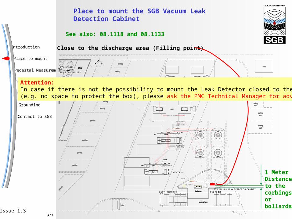
Place to mount the SGB Vacuum Leak Detection Cabinet
See also: 08.1118 and 08.1133
Close to the discharge area (Filling point)
500
350 600
variable
400
variable
isla
nd
1200
4500
500
350 600
variable
400
variable
isla
nd 1
200
4500PRODUCT PIPELINE
FILL POINT
VENTS
VR
REGULAR PETROLV-POWER PETROLV-POWER DIESELDIESEL
REGULAR PETROL
REGULAR PETROL
REGULAR PETROLV-POWER PETROLV-POWER DIESELDIESEL
63mm UPP
500
350 600
variable
400
variable
isla
nd
1200
4500
500
350 600
variable
400
variable
isla
nd 1
200
4500
1-
1-
TAN
K 2
RE
GU
LAR
PE
TR
OL
TAN
K 4
DIE
SE
L
TAN
K 1
V-P
OW
ER
PE
TR
OL
TAN
K 3
V-P
OW
ER
DIE
SE
L
SGB VACUUM LEAK DETECTION CABINETEARTH CHAMBER FILL POINT
VENTS
TO SWITCH BOARD,ATG CONSOLE ANDFORECOURT CONTROLLER
1 MeterDistanceto thecorbingsorbollards
Attention:In case if there is not the possibility to mount the Leak Detector closed to the filling(e.g. no space to protect the box), please ask the PMC Technical Manager for advice

Introduction
Conduits, general
Contact to SGB
Conduit Plan
Grounding
Place to mount
Pedestal Measurem.
A/4Issue 1.3
Place to mount the SGB Vacuum Leak Detection Cabinet
DO‘s: - Place closed to the filling-point
DONT‘s: - „too-early“ mounting of the box Due to risks of damages during site civil works- Wrong conduits are used Entry seals to avoid migration of vapors cannot be installed

Introduction
Conduits, general
Contact to SGB
Conduit Plan
Grounding
Place to mount
Pedestal Measurem.
A/5Issue 1.3
Pedestal for the Leak Detection Cabinet
There a pedestal has to be built:
1. Horizontal measurements of the concrete pedestal
2. Measurements of the protection box
3. Space for the conduits (opening of the protection box)RED AREA is the space to terminate the conduits
600 mm
1100 mm
300 mm
800 mm
700 mm
180 mm
Introduction
Conduits, general
Contact to SGB
Conduit Plan
Grounding
Place to mount
Pedestal Measurem.
A/6Issue 1.3
Pedestal for the Leak Detection Cabinet
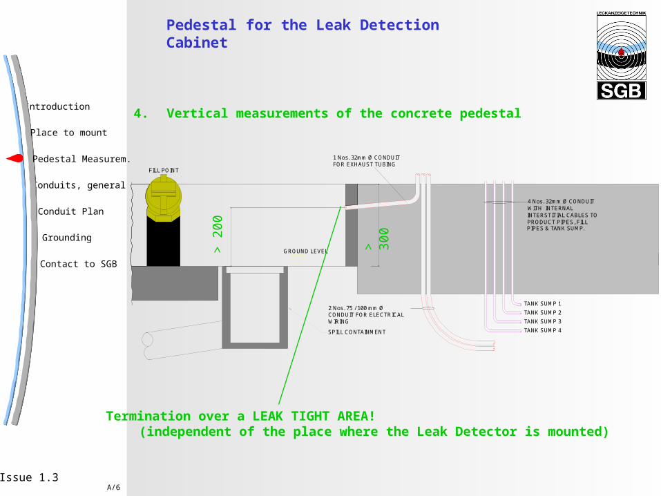
4. Vertical measurements of the concrete pedestal
2 Nos. 75 / 100 mm Ø CONDUIT FOR ELECTRICALWIRING
GROUND LEVEL
4 Nos. 32mm Ø CONDUIT
1 Nos. 32mm Ø CONDUITFOR EXHAUST TUBING
WITH INTERNALINTERSTITIAL CABLES TOPRODUCT PIPES, FILLPIPES & TANK SUMP.
TANK SUMP 1
TANK SUMP 2
TANK SUMP 3
TANK SUMP 4SPILL CONTAINMENT
FILL POINT
> 2
00
> 3
00
Termination over a LEAK TIGHT AREA!(independent of the place where the Leak Detector is mounted)

Introduction
Conduits, general
Contact to SGB
Conduit Plan
Grounding
Place to mount
Pedestal Measurem.
A/7Issue 1.3
Conduits, general
Conduits are required for:
1. Electrical wiring between Protection Box and Indicating Unit (Shop)(for information: 4 wires + Ground)Electrical wiring between Protection Box and VISY INPUT (Fafnir)(for information: 2 wires per sensor in one cable e.g. 4 sensors means one cable with 8 wires)
2. The tubing between the monitored interstitial space of the pressure lines and the manifold in the Protection BoxCAUTION: If there are more than 3 tubes to routed through oneconduit, install a second conduit to the same manhole.
3. The Tubing for the exhaust line
An Animation for these Conduits follows next page!
See also: 08.1118 and 08.1114 + 08.1116

Introduction
Conduits, general
Contact to SGB
Conduit Plan
Grounding
Place to mount
Pedestal Measurem.
A/8Issue 1.3
Conduits, general
Requirements for the conduits:
1. Routed with a continuous fall to the manhole
2. Buried at a depth that the tubes are Frost protected (~ 60 cm)
3. The distance between manhole and Leak Detector should not exceed 50 m
4. Routed from every manhole to the place where the Leak Detector ismounted (concrete pedestal)
5. D=75 mm (or 100 mm) for electrical wiring
6. D=32 mm, for Tubing, recommendation: UPP
7. Use specified Conduit Entry Boot to enter the manhole
See also: 08.1123

Introduction
Conduits, general
Contact to SGB
Conduit Plan
Grounding
Place to mount
Pedestal Measurem.
A/9Issue 1.3
TAN
K 2
RE
GU
LAR
PE
TR
OL
TAN
K 4
DIE
SE
L
TAN
K 1
V-P
OW
ER
PE
TR
OL
TAN
K 3
V-P
OW
ER
DIE
SE
L
SGB VACUUM LEAK DETECTION CABINET
FILL POINT
VENTS
Conduit Plan Conduit exhaust, 32 mm
Conduit pressure lines, 32 mm
Conduit electrical, 75 or 100 mm

Introduction
Conduits, general
Contact to SGB
Conduit Plan
Grounding
Place to mount
Pedestal Measurem.
A/10Issue 1.3
Conduit Plan Conduit exhaust, 32 mm
Conduit pressure lines, 32 mm
Conduit electrical, 75 or 100 mm
2 Nos. 75 / 100 mm Ø CONDUIT FOR ELECTRICALWIRING
GROUND LEVEL
4 Nos. 32mm Ø CONDUIT
1 Nos. 32mm Ø CONDUITFOR EXHAUST TUBING
WITH INTERNALINTERSTITIAL CABLES TOPRODUCT PIPES, FILLPIPES & TANK SUMP.
TANK SUMP 1
TANK SUMP 2
TANK SUMP 3
TANK SUMP 4SPILL CONTAINMENT
FILL POINT

Introduction
Conduits, general
Contact to SGB
Conduit Plan
Grounding
Place to mount
Pedestal Measurem.
A/11Issue 1.3
Routing of the Conduits
Place where the concrete pedestalfor the leak detector will be built
Conduits for theleak detection system

Introduction
Conduits, general
Contact to SGB
Conduit Plan
Grounding
Place to mount
Pedestal Measurem.
A/12Issue 1.3
Grounding of the box
See also: 08.1118 and 08.1137
TAN
K 2
RE
GU
LAR
PE
TR
OL
TAN
K 4
DIE
SE
L
SGB VACUUM LEAK DETECTION CABINETEARTH CHAMBER FILL POINT
VENTS
Prepare the grounding, that also the protection box can be grounded
Grounding point in the box
Existing grounding plan

Introduction
Conduits, general
Contact to SGB
Conduit Plan
Grounding
Place to mount
Pedestal Measurem.
A/13Issue 1.3
If you need more information
Martin Huecking + 49 (0)271-48964-40(Technical Director) + 49 (0)160-964 63 229
Jost Berg + 49 (0)271-48964-14(President) [email protected]
Hans-Gerd Jersemann + 49 (0)271-48964-44(Sales Engineer) [email protected]
or if you have proposals to optimize our documentation
or if you need assistance for a site lay-out
Please contact:

![[Strangeways I.C.] Precipitation Theory, Measurem(BookFi.org)](https://img.pdfslide.us/doc/110x75/55cf8e14550346703b8e50e0/strangeways-ic-precipitation-theory-measurembookfiorg.jpg)