Embed Size (px)
Citation preview

Introduction 1-1
Chapter 1Part 3Delay, loss and throughput
These slides derived from Computer Networking: A Top Down Approach ,6th edition. Jim Kurose, Keith RossAddison-Wesley, March 2012.
Comp 365Computer Networks
Fall 2014

Introduction 1-2
Chapter 1: roadmap
1.1 What is the Internet?1.2 Network edge
end systems, access networks, links
1.3 Network core circuit switching, packet switching, network structure
1.4 Delay, loss and throughput in packet-switched networks
1.5 Protocol layers, service models1.6 Networks under attack: security1.7 History

Delay, Loss, and Throughput
Three concepts important at all layers of networks
Want to minimize delay and loss, maximize throughput
Introduction 1-3

Introduction 1-4
How do loss and delay occur?packets queue in router buffers packet arrival rate to link exceeds output link
capacity packets queue, wait for turn
A
B
packet being transmitted (delay)
packets queueing (delay)
free (available) buffers: arriving packets dropped (loss) if no free buffers

Introduction 1-5
Four sources of packet delay
nodal processing queueing Transmission delay Propagation delay
AB
propagation
transmission
nodalprocessing queueing
We’ll study routers in detail in chapter 4
We’ll study routers in detail in chapter 4

Introduction 1-6
Four sources of packet delay
1. dproc (nodal processing): check bit errors determine output link Typical delay: < msec
AB
propagation
transmission
nodalprocessing queueing
We’ll study routers in detail in chapter 4
We’ll study routers in detail in chapter 4

Introduction 1-7
Four sources of packet delay
AB
propagation
transmission
nodalprocessing queueing
2. dqueue (queueing) time waiting at output
link for transmission depends on congestion
level of router Typical delay: micro to
milliseconds
We’ll study routers in detail in chapter 4
We’ll study routers in detail in chapter 4
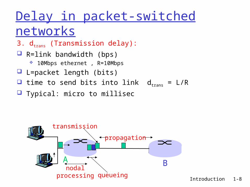
Introduction 1-8
Delay in packet-switched networks3. dtrans (Transmission delay): R=link bandwidth (bps)
10Mbps ethernet , R=10Mbps
L=packet length (bits) time to send bits into link dtrans = L/R Typical: micro to millisec
A B
propagation
transmission
nodalprocessing queueing
Introduction 1-9
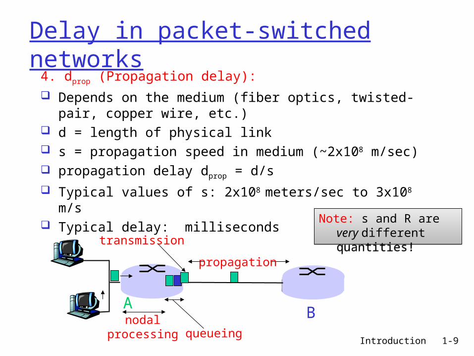
Delay in packet-switched networks
4. dprop (Propagation delay): Depends on the medium (fiber optics, twisted-pair,
copper wire, etc.) d = length of physical link s = propagation speed in medium (~2x10⁸ m/sec) propagation delay dprop = d/s Typical values of s: 2x10⁸ meters/sec to 3x10⁸ m/s Typical delay: milliseconds
AB
propagation
transmission
nodalprocessing queueing
Note: s and R are very different quantities!
Note: s and R are very different quantities!
Introduction 1-10
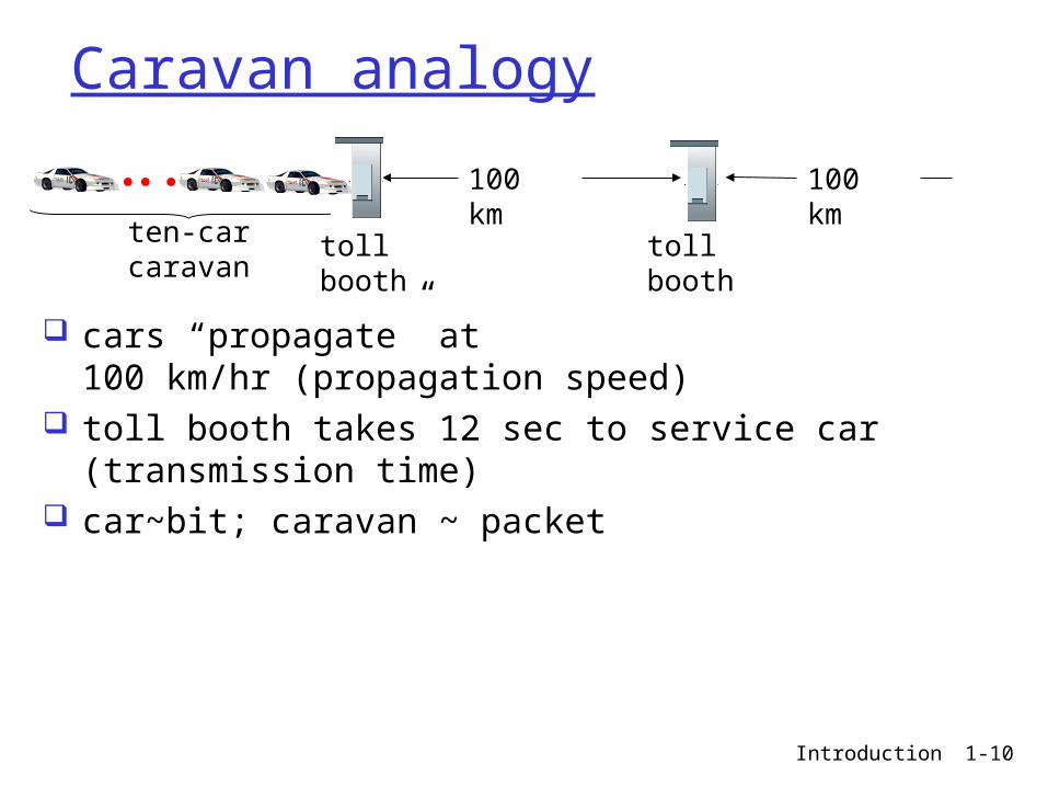
Caravan analogy
cars “propagate” at 100 km/hr (propagation speed)
toll booth takes 12 sec to service car (transmission time)
car~bit; caravan ~ packet
toll booth
toll booth
ten-car caravan
100 km
100 km

Introduction 1-11
Caravan analogy
Q: How long until caravan is lined up before 2nd toll booth?
Time to “push” entire caravan through toll booth onto highway = 12*10 = 120 sec
Time for last car to propagate from 1st to 2nd toll both: 100km/(100km/hr)= 1 hr
A: 62 minutes
toll booth
toll booth
ten-car caravan
100 km
100 km

Introduction 1-12
Caravan analogy (more)
Cars now “propagate” at 1000 km/hr Toll booth now takes 1 min to service a car Q: Will cars arrive to 2nd booth before all cars
serviced at 1st booth?
toll booth
toll booth
ten-car caravan
100 km
100 km

Introduction 1-13
Caravan analogy (more)
Cars now “propagate” at 1000 km/hr Toll booth now takes 1 min to service a car Q: Will cars arrive to 2nd booth before all cars
serviced at 1st booth? Yes! After 7 min, 1st car at 2nd booth and 3 cars
still at 1st booth. 1st bit of packet can arrive at 2nd router before
packet is fully transmitted at 1st router! See Ethernet applet at AWL Web site
toll booth
toll booth
ten-car caravan
100 km
100 km

Introduction 1-14
Nodal delay
dproc = processing delay typically a few microsecs or less
dqueue = queuing delay depends on congestion
dtrans = transmission delay = L/R, significant for low-speed links
dprop = propagation delay a few microsecs to hundreds of msecs

Example: End-to-end delay
Do Interactive Exercise “one-hop delay” from the online student resources:
http://wps.pearsoned.com/ecs_kurose_compnetw_6/216/55463/14198700.cw/index.html
Introduction 1-15

Example: End-to-end delay
Do Interactive Exercise “End-to-end delay” from the online student resources:
http://wps.pearsoned.com/ecs_kurose_compnetw_6/216/55463/14198700.cw/index.html
Introduction 1-16

Introduction 1-17
Queueing delay (revisited)
R=link bandwidth (bps) this is transmission time
L=packet length (bits) a=average packet arrival
rate
traffic intensity = La/R
La/R ~ 0: average queueing delay small La/R -> 1: delays become large La/R > 1: more “work” arriving than can
be serviced, average delay infinite!
Introduction 1-18
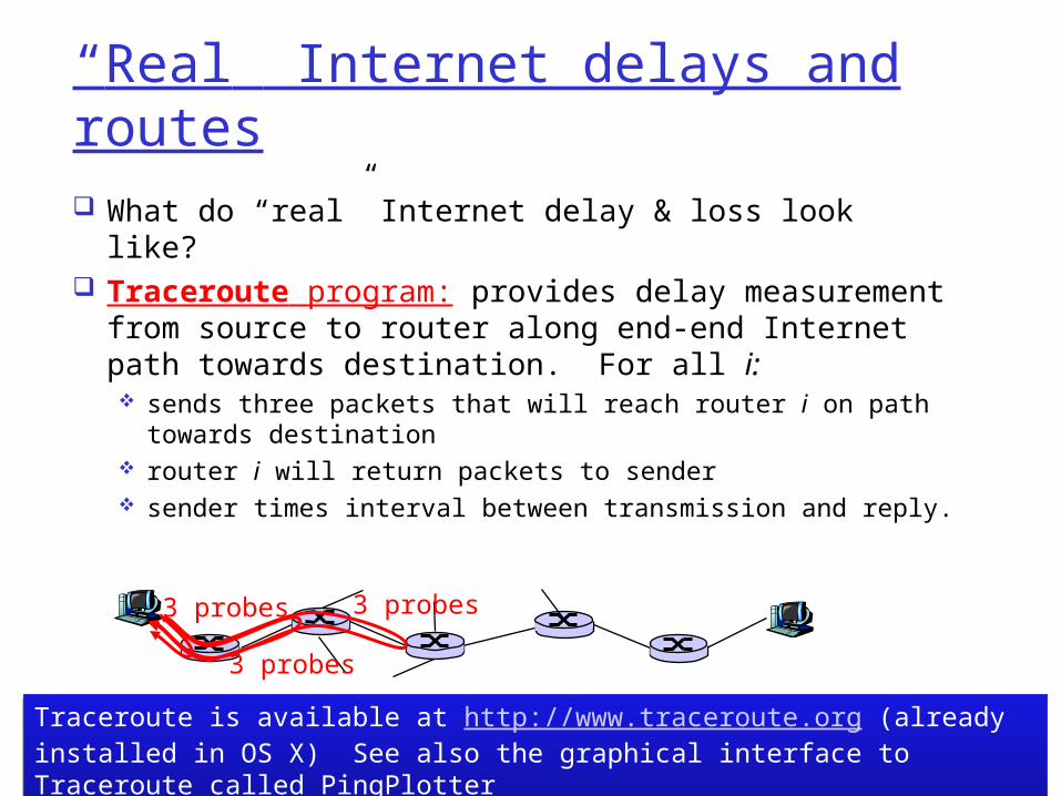
“Real” Internet delays and routes
What do “real” Internet delay & loss look like? Traceroute program: provides delay
measurement from source to router along end-end Internet path towards destination. For all i: sends three packets that will reach router i on path
towards destination router i will return packets to sender sender times interval between transmission and reply.
3 probes
3 probes
3 probes
Traceroute is available at http://www.traceroute.org (already installed in OS X) See also the graphical interface to Traceroute called PingPlotter Traceroute is available at http://www.traceroute.org (already installed in OS X) See also the graphical interface to Traceroute called PingPlotter

Introduction 1-19
“Real” Internet delays and routes
1 cs-gw (128.119.240.254) 1 ms 1 ms 2 ms2 border1-rt-fa5-1-0.gw.umass.edu (128.119.3.145) 1 ms 1 ms 2 ms3 cht-vbns.gw.umass.edu (128.119.3.130) 6 ms 5 ms 5 ms4 jn1-at1-0-0-19.wor.vbns.net (204.147.132.129) 16 ms 11 ms 13 ms 5 jn1-so7-0-0-0.wae.vbns.net (204.147.136.136) 21 ms 18 ms 18 ms 6 abilene-vbns.abilene.ucaid.edu (198.32.11.9) 22 ms 18 ms 22 ms7 nycm-wash.abilene.ucaid.edu (198.32.8.46) 22 ms 22 ms 22 ms8 62.40.103.253 (62.40.103.253) 104 ms 109 ms 106 ms9 de2-1.de1.de.geant.net (62.40.96.129) 109 ms 102 ms 104 ms10 de.fr1.fr.geant.net (62.40.96.50) 113 ms 121 ms 114 ms11 renater-gw.fr1.fr.geant.net (62.40.103.54) 112 ms 114 ms 112 ms12 nio-n2.cssi.renater.fr (193.51.206.13) 111 ms 114 ms 116 ms13 nice.cssi.renater.fr (195.220.98.102) 123 ms 125 ms 124 ms14 r3t2-nice.cssi.renater.fr (195.220.98.110) 126 ms 126 ms 124 ms15 eurecom-valbonne.r3t2.ft.net (193.48.50.54) 135 ms 128 ms 133 ms16 194.214.211.25 (194.214.211.25) 126 ms 128 ms 126 ms17 * * *18 * * *19 fantasia.eurecom.fr (193.55.113.142) 132 ms 128 ms 136 ms
traceroute: gaia.cs.umass.edu to www.eurecom.frThree delay measurements from gaia.cs.umass.edu to cs-gw.cs.umass.edu
* means no response (probe lost, router not replying)
trans-oceaniclink

traceroute
How do you use it? A230247$ traceroute gaia.cs.umass.edu
Introduction 1-20
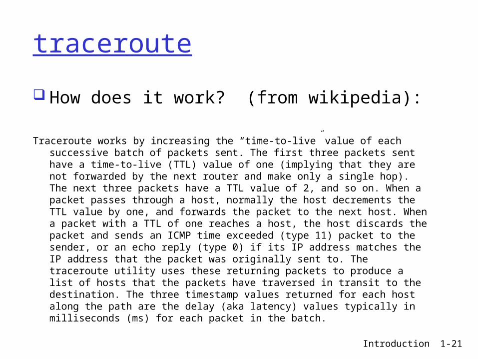
traceroute
How does it work? (from wikipedia):
Traceroute works by increasing the “time-to-live” value of each successive batch of packets sent. The first three packets sent have a time-to-live (TTL) value of one (implying that they are not forwarded by the next router and make only a single hop). The next three packets have a TTL value of 2, and so on. When a packet passes through a host, normally the host decrements the TTL value by one, and forwards the packet to the next host. When a packet with a TTL of one reaches a host, the host discards the packet and sends an ICMP time exceeded (type 11) packet to the sender, or an echo reply (type 0) if its IP address matches the IP address that the packet was originally sent to. The traceroute utility uses these returning packets to produce a list of hosts that the packets have traversed in transit to the destination. The three timestamp values returned for each host along the path are the delay (aka latency) values typically in milliseconds (ms) for each packet in the batch.
Introduction 1-21

“Real” Internet delays and routes
Exercise Each person pick a different time Each person pick a different destination
(continental or outside continent) Use traceroute or PingPlotter Report back results tomorrow
Introduction 1-22

Introduction 1-23
Packet loss
queue (aka buffer) preceding link in buffer has finite capacity
packet arriving to full queue dropped (aka lost)
lost packet may be retransmitted by previous node, by source end system, or not at allA
B
packet being transmitted
packet arriving tofull buffer is lost
buffer (waiting area)

Other Delays
Dial-up modems have large encoding/decoding delays (other technologies don’t)
Some protocols purposely delay transmission (to share medium). Chap 5.
Media packetization delay (as in VOIP) Must digitize speech & encode it
Introduction 1-24

1-25
Throughput
throughput: rate (bits/time unit) at which bits transferred between sender/receiver
instantaneous: rate at given point in time at which the destination host is receiving the file
average: rate over longer period of time
File = F bitstransfer takes T seconds for host to receiveaverage throughput = F/T bits/sec
Some downloading apps display the instantaneous rate as you download
Some downloading apps display the instantaneous rate as you download

1-26
Throughput
throughput: rate (bits/time unit) at which bits transferred between sender/receiver
throughput is determined by the transmission and propagation rates of all the switches and links and by the delays encountered
With throughput, however, we don’t look for individual rates/delays but just measure how fast bits arrive.
throughput is a coarse-grained measure

Introduction 1-27
Throughput
throughput: rate (bits/time unit) at which bits transferred between sender/receiver
server, withfile of F bits
to send to client
link capacity
Rs bits/sec
link capacity
Rc bits/sec pipe that can carry
fluid at rate
Rs bits/sec)
pipe that can carryfluid at rate
Rc bits/sec)
server sends bits
(fluid) into pipe
the server can pump Rs bits through the first pipe and the router can pump Rc bits through the second pipe
Think of throughput as the width of the pipe not the length of the pipe.
Think of throughput as the width of the pipe not the length of the pipe.

Introduction 1-28
Throughput (more)
Rs < Rc What is average end-end throughput?
Rs bits/sec Rc bits/sec
link on end-end path that constrains end-end throughput
bottleneck link
The server can only pump Rs bits through its pipe. The router could pump more, but it’s only receiving Rs bits so it can only pump Rs bits.

Introduction 1-29
Throughput (more)
Rs > Rc What is average end-end throughput?
Rs bits/sec Rc bits/sec
link on end-end path that constrains end-end throughput
bottleneck link
The router receives Rs bits, but can only pump Rc
bits so the rate at which the client receives bits is Rc
Throughput
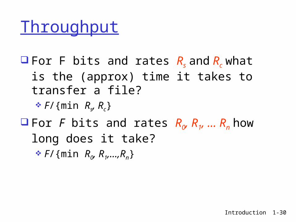
For F bits and rates Rs and Rc what is the (approx) time it takes to transfer a file? F/{min Rs, Rc}
For F bits and rates R0, R1, … Rn how long does it take? F/{min R0, R1,…,Rn}
Introduction 1-30

Introduction 1-31
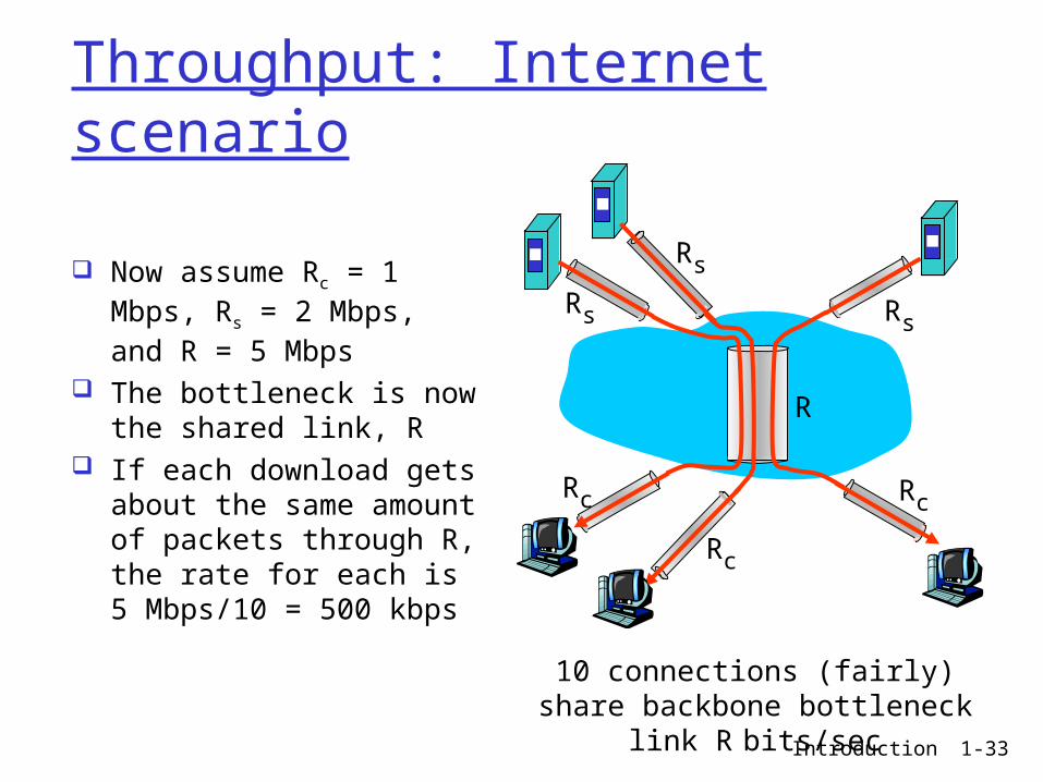
Throughput: Internet scenario
10 connections (fairly) share backbone bottleneck link R
bits/sec
Rs
Rs
Rs
Rc
Rc
Rc
R
per-connection end-end throughput: min(Rc,Rs,R/10)
in practice: Rc or Rs is often bottleneck
Backbone is, in general, over provisioned; seldom causes delay. Tier 2, 3, etc. cause
delay.
Backbone is, in general, over provisioned; seldom causes delay. Tier 2, 3, etc. cause
delay.

Introduction 1-32
Throughput: Internet scenario
10 connections (fairly) share backbone bottleneck link R
bits/sec
Rs
Rs
Rs
Rc
Rc
Rc
R
Assume all connections except Rc and Rs and R are very large
if R >> Rc and Rs the bottleneck is Rc or Rs
Backbone is, in general, over provisioned; seldom causes delay. Tier 2, 3, etc. cause
delay.
Backbone is, in general, over provisioned; seldom causes delay. Tier 2, 3, etc. cause
delay.
Introduction 1-33
Throughput: Internet scenario
10 connections (fairly) share backbone bottleneck link R
bits/sec
Rs
Rs
Rs
Rc
Rc
Rc
R
Now assume Rc = 1 Mbps, Rs = 2 Mbps, and R = 5 Mbps
The bottleneck is now the shared link, R
If each download gets about the same amount of packets through R, the rate for each is 5 Mbps/10 = 500 kbps
Throughput: Example
Do Interactive Exercise “End to End Throughput” from
http://wps.pearsoned.com/ecs_kurose_compnetw_6/216/55463/14198700.cw/index.html
Introduction 1-34


![64250639 HSDPA Low Throughput[1]](https://img.pdfslide.us/doc/110x75/577cbce71a28aba7118dd370/64250639-hsdpa-low-throughput1.jpg)