Embed Size (px)
Citation preview
Part 5: Data Link Layer
CSE 3461/5461
Reading: Chapter 5, Kurose and Ross
1
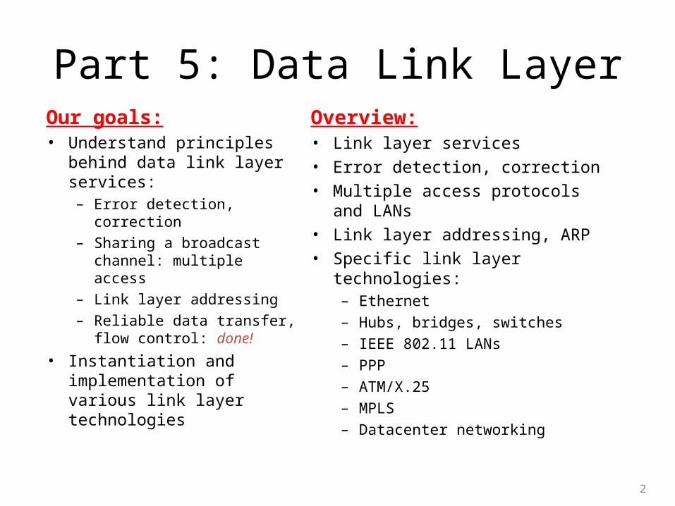
Part 5: Data Link LayerOur goals: • Understand principles behind
data link layer services:– Error detection, correction
– Sharing a broadcast channel: multiple access
– Link layer addressing
– Reliable data transfer, flow control: done!
• Instantiation and implementation of various link layer technologies
Overview:• Link layer services
• Error detection, correction
• Multiple access protocols and LANs
• Link layer addressing, ARP
• Specific link layer technologies:– Ethernet
– Hubs, bridges, switches
– IEEE 802.11 LANs
– PPP
– ATM/X.25
– MPLS
– Datacenter networking
2
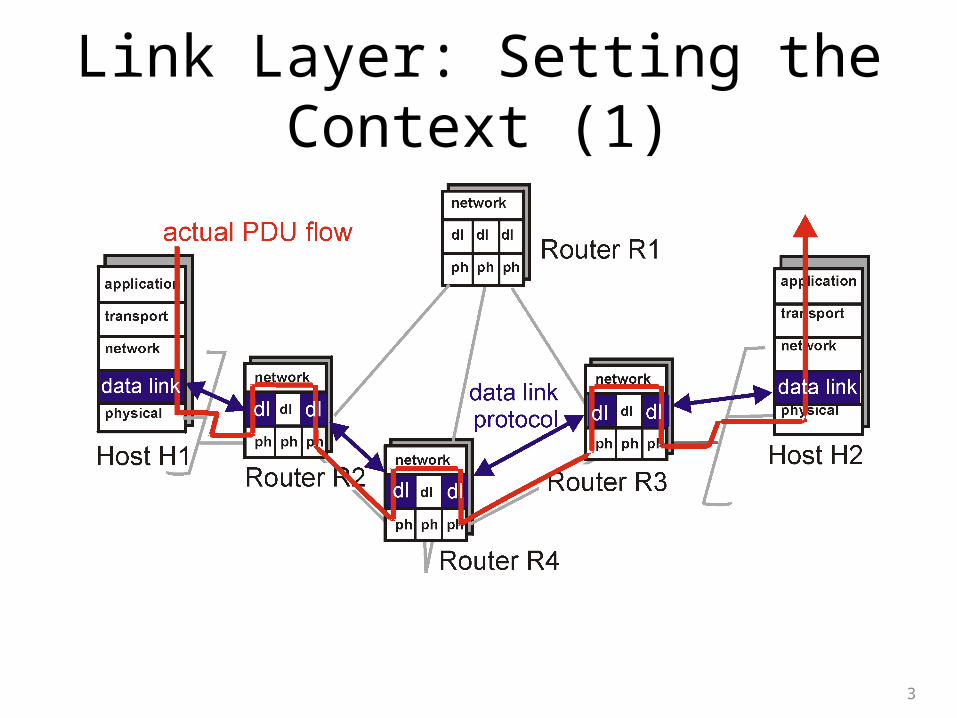
Link Layer: Setting the Context (1)
3
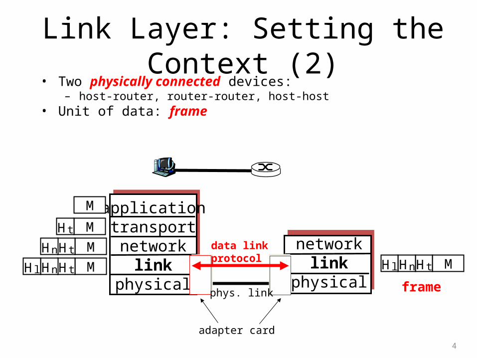
Link Layer: Setting the Context (2)• Two physically connected devices:
– host-router, router-router, host-host• Unit of data: frame
4
applicationtransportnetwork
linkphysical
networklink
physical
M
M
M
M
Ht
HtHn
HtHnHl MHtHnHl
framephys. link
data linkprotocol
adapter card
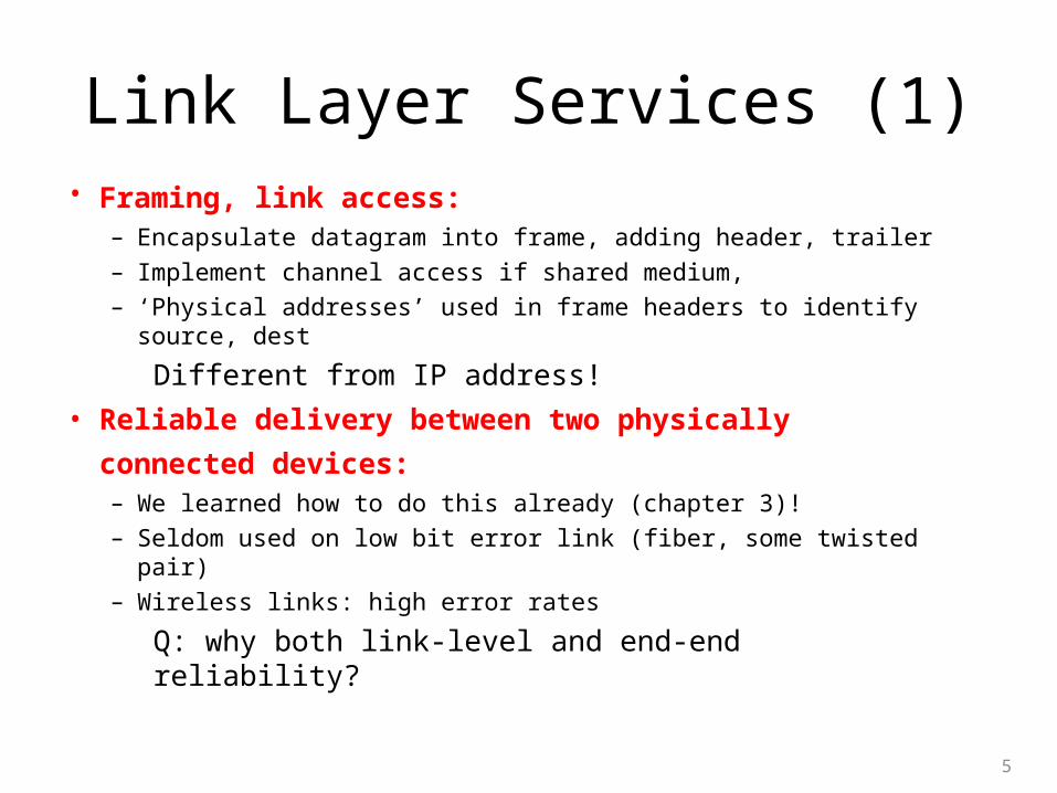
Link Layer Services (1)• Framing, link access:
– Encapsulate datagram into frame, adding header, trailer
– Implement channel access if shared medium,
– ‘Physical addresses’ used in frame headers to identify source, dest
Different from IP address!
• Reliable delivery between two physically connected
devices: – We learned how to do this already (chapter 3)!
– Seldom used on low bit error link (fiber, some twisted pair)
– Wireless links: high error rates
Q: why both link-level and end-end reliability?
5
Link Layer Services (2)
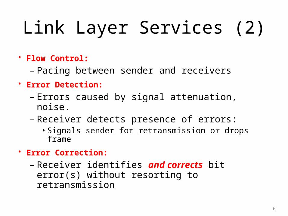
• Flow Control: – Pacing between sender and receivers
• Error Detection: – Errors caused by signal attenuation, noise. – Receiver detects presence of errors: • Signals sender for retransmission or drops frame
• Error Correction: – Receiver identifies and corrects bit error(s)
without resorting to retransmission
6
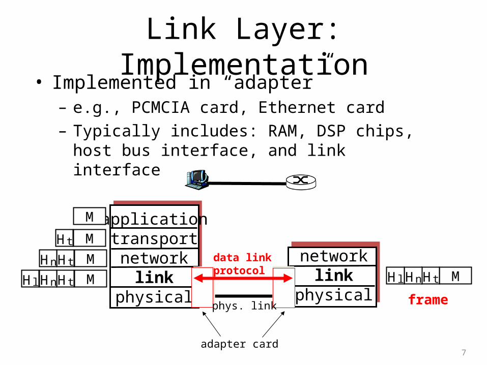
Link Layer: Implementation• Implemented in “adapter” – e.g., PCMCIA card, Ethernet card
– Typically includes: RAM, DSP chips, host bus interface, and link interface
7
applicationtransportnetwork
linkphysical
networklink
physical
M
M
M
M
Ht
HtHn
HtHnHl MHtHnHl
framephys. link
data linkprotocol
adapter card
Error Detection
8
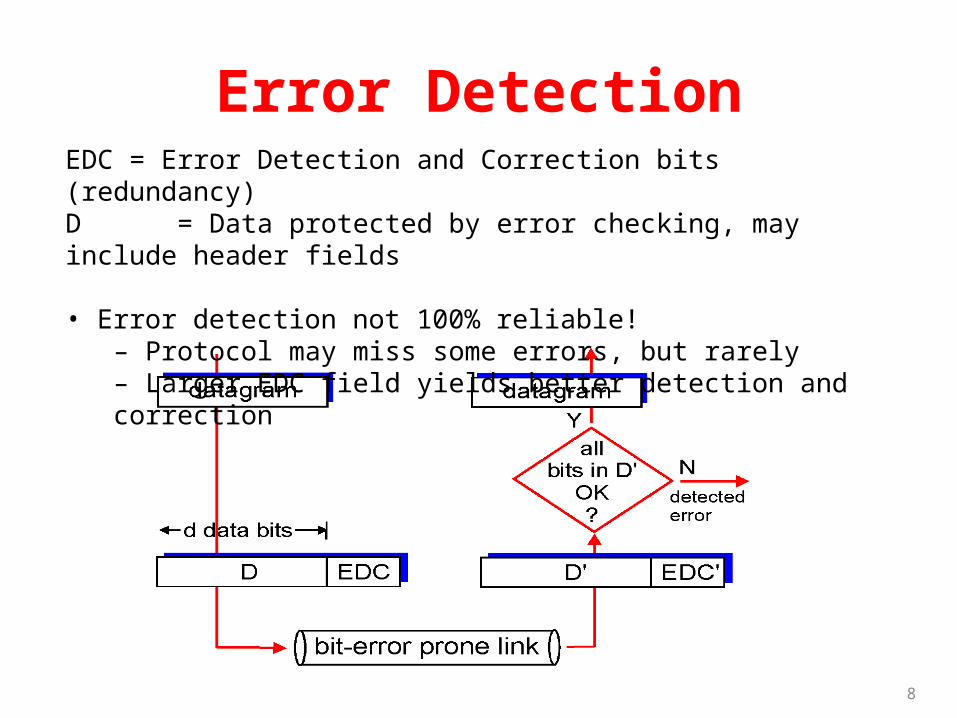
EDC = Error Detection and Correction bits (redundancy)D = Data protected by error checking, may include header fields
• Error detection not 100% reliable!– Protocol may miss some errors, but rarely– Larger EDC field yields better detection and correction
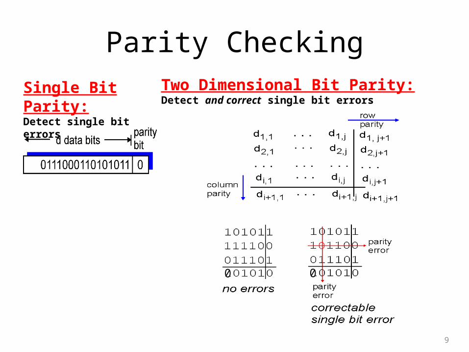
Parity Checking
9
Single Bit Parity:Detect single bit errors
Two Dimensional Bit Parity:Detect and correct single bit errors
0 0
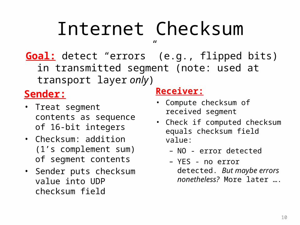
Internet Checksum
Sender:• Treat segment contents as
sequence of 16-bit integers
• Checksum: addition (1’s complement sum) of segment contents
• Sender puts checksum value into UDP checksum field
Receiver:• Compute checksum of received
segment
• Check if computed checksum equals checksum field value:
– NO - error detected
– YES - no error detected. But maybe errors nonetheless? More later ….
10
Goal: detect “errors” (e.g., flipped bits) in transmitted segment (note: used at transport layer only)
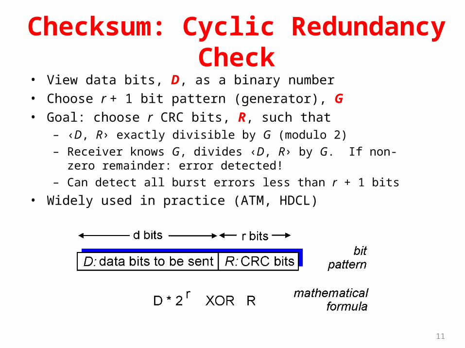
Checksum: Cyclic Redundancy Check• View data bits, D, as a binary number
• Choose r + 1 bit pattern (generator), G
• Goal: choose r CRC bits, R, such that– ‹D, R› exactly divisible by G (modulo 2)
– Receiver knows G, divides ‹D, R› by G. If non-zero remainder: error detected!
– Can detect all burst errors less than r + 1 bits
• Widely used in practice (ATM, HDCL)
11
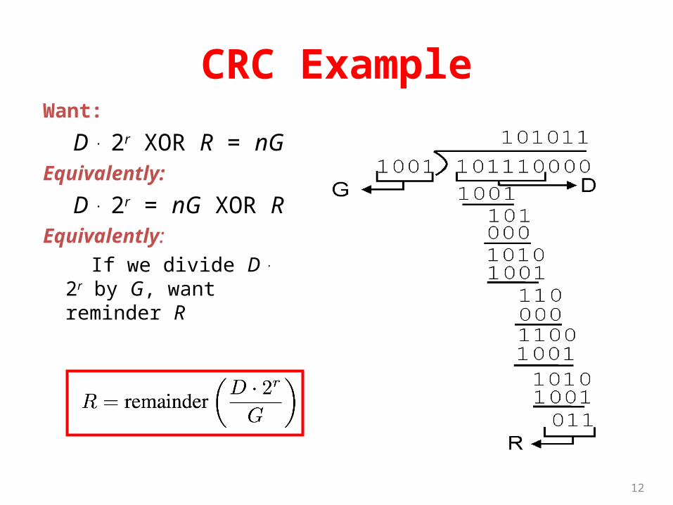
CRC ExampleWant:
D . 2r XOR R = nGEquivalently:
D . 2r = nG XOR R Equivalently:
If we divide D . 2r by G, want reminder R
12
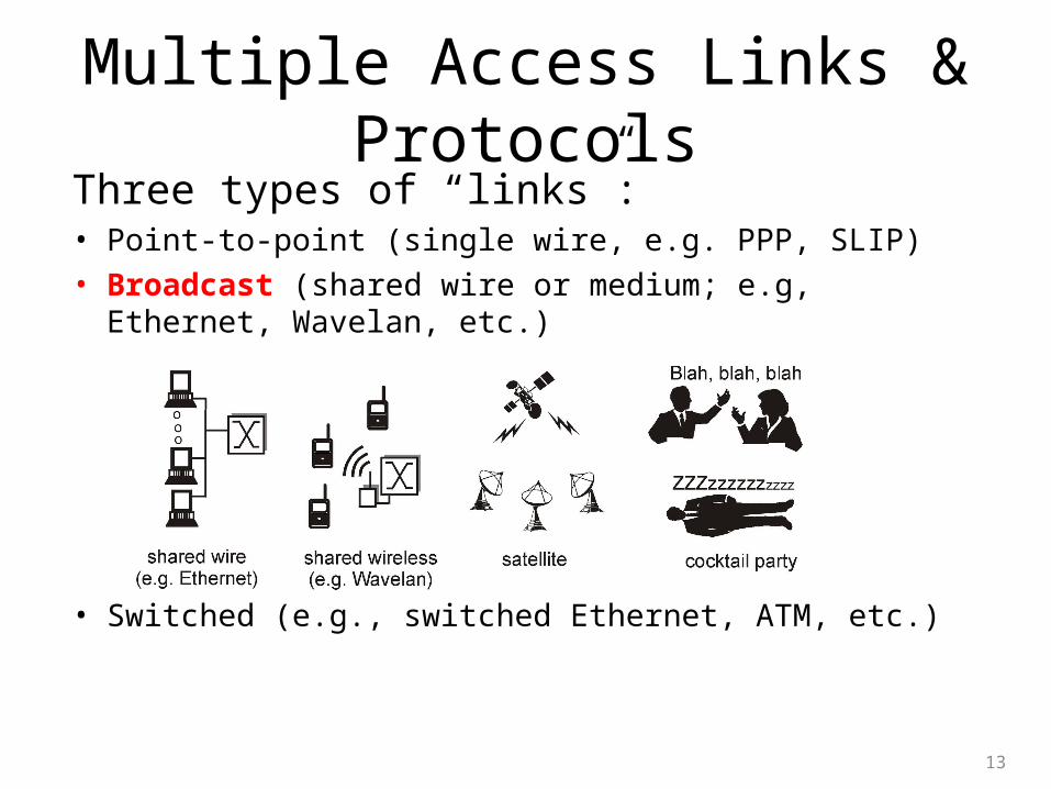
Multiple Access Links & ProtocolsThree types of “links”:• Point-to-point (single wire, e.g. PPP, SLIP)
• Broadcast (shared wire or medium; e.g, Ethernet, Wavelan, etc.)
• Switched (e.g., switched Ethernet, ATM, etc.)
13
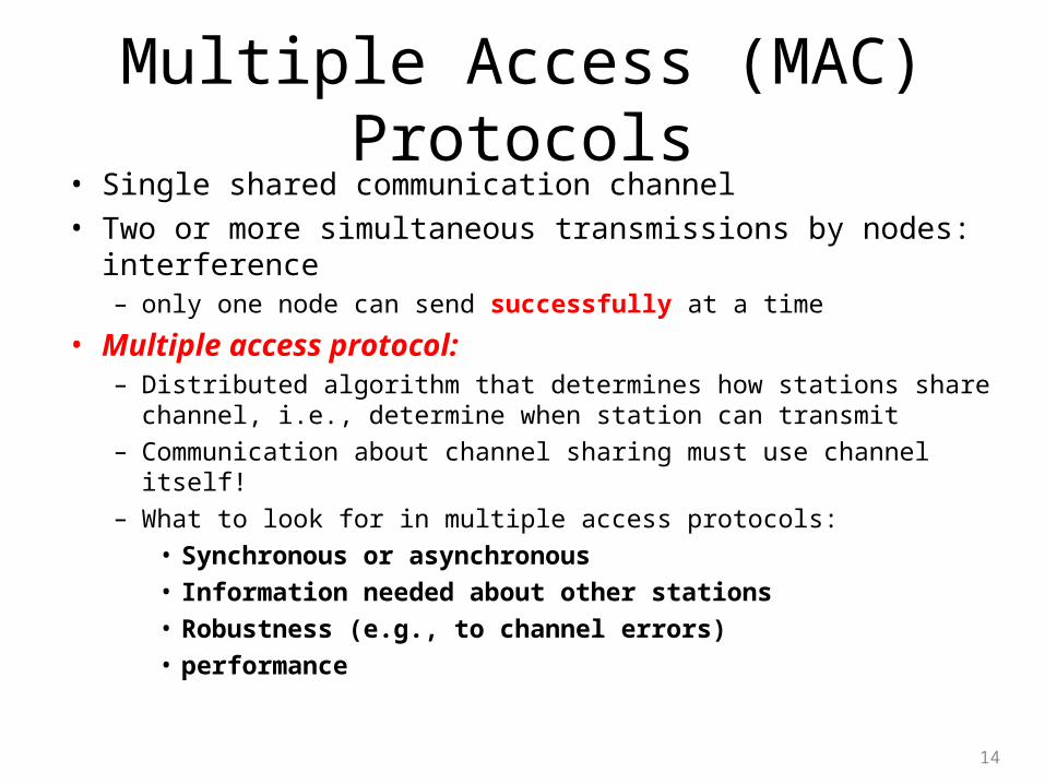
Multiple Access (MAC) Protocols• Single shared communication channel
• Two or more simultaneous transmissions by nodes: interference – only one node can send successfully at a time
• Multiple access protocol:– Distributed algorithm that determines how stations share channel, i.e.,
determine when station can transmit
– Communication about channel sharing must use channel itself!
– What to look for in multiple access protocols:
• Synchronous or asynchronous
• Information needed about other stations
• Robustness (e.g., to channel errors)
• performance
14
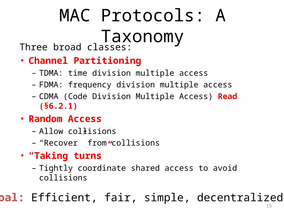
MAC Protocols: A TaxonomyThree broad classes:
• Channel Partitioning– TDMA: time division multiple access
– FDMA: frequency division multiple access
– CDMA (Code Division Multiple Access) Read (§6.2.1)
• Random Access– Allow collisions
– “Recover” from collisions
• “Taking turns”– Tightly coordinate shared access to avoid collisions
15
Goal: Efficient, fair, simple, decentralized
Random Access Protocols
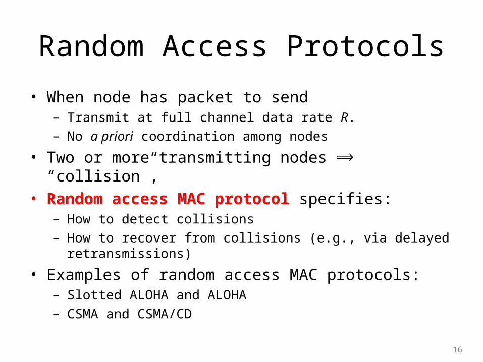
• When node has packet to send– Transmit at full channel data rate R.
– No a priori coordination among nodes
• Two or more transmitting nodes “collision”,⟹• Random access MAC protocol specifies:
– How to detect collisions
– How to recover from collisions (e.g., via delayed retransmissions)
• Examples of random access MAC protocols:– Slotted ALOHA and ALOHA
– CSMA and CSMA/CD
16
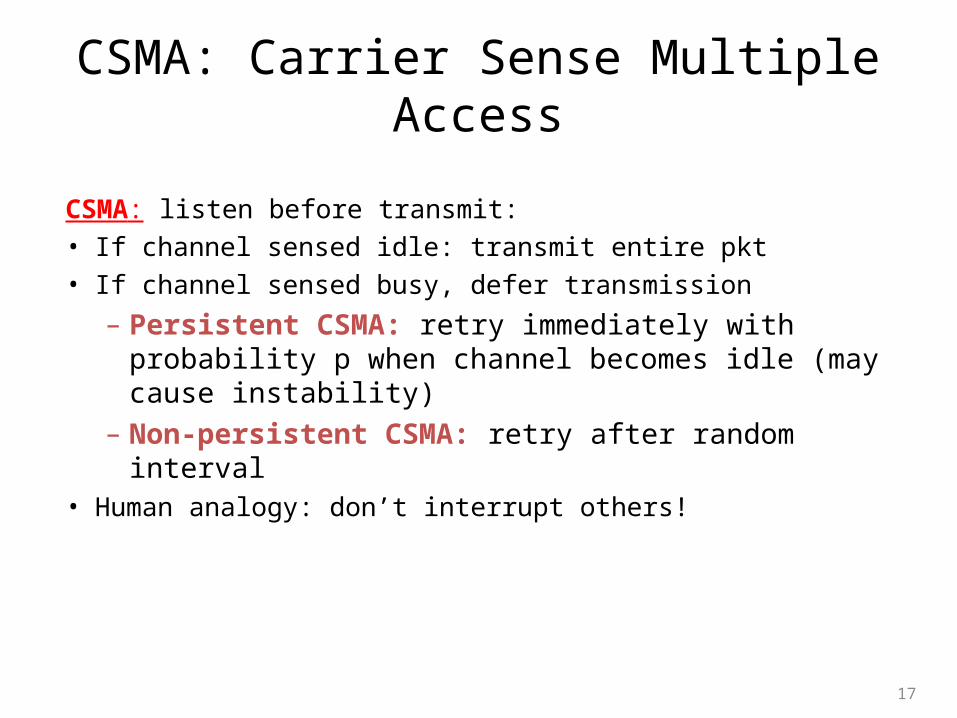
CSMA: Carrier Sense Multiple Access
CSMA: listen before transmit:
• If channel sensed idle: transmit entire pkt
• If channel sensed busy, defer transmission
– Persistent CSMA: retry immediately with probability p when channel becomes idle (may cause instability)
– Non-persistent CSMA: retry after random interval• Human analogy: don’t interrupt others!
17
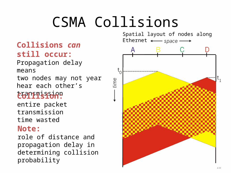
CSMA Collisions
18
Collisions can still occur:Propagation delay means two nodes may not yearhear each other’s transmission
Collision:entire packet transmission time wasted
Spatial layout of nodes along Ethernet
Note:role of distance and propagation delay in determining collision probability
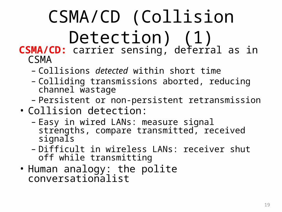
CSMA/CD (Collision Detection) (1)CSMA/CD: carrier sensing, deferral as in CSMA– Collisions detected within short time– Colliding transmissions aborted, reducing channel
wastage – Persistent or non-persistent retransmission
• Collision detection: – Easy in wired LANs: measure signal strengths,
compare transmitted, received signals– Difficult in wireless LANs: receiver shut off while
transmitting• Human analogy: the polite conversationalist
19
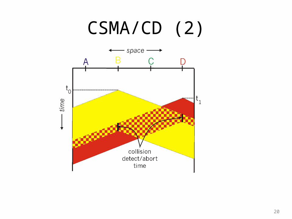
CSMA/CD (2)
20
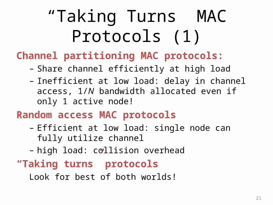
“Taking Turns” MAC Protocols (1)
Channel partitioning MAC protocols:– Share channel efficiently at high load
– Inefficient at low load: delay in channel access, 1/N bandwidth allocated even if only 1 active node!
Random access MAC protocols– Efficient at low load: single node can fully utilize channel
– high load: collision overhead
“Taking turns” protocolsLook for best of both worlds!
21
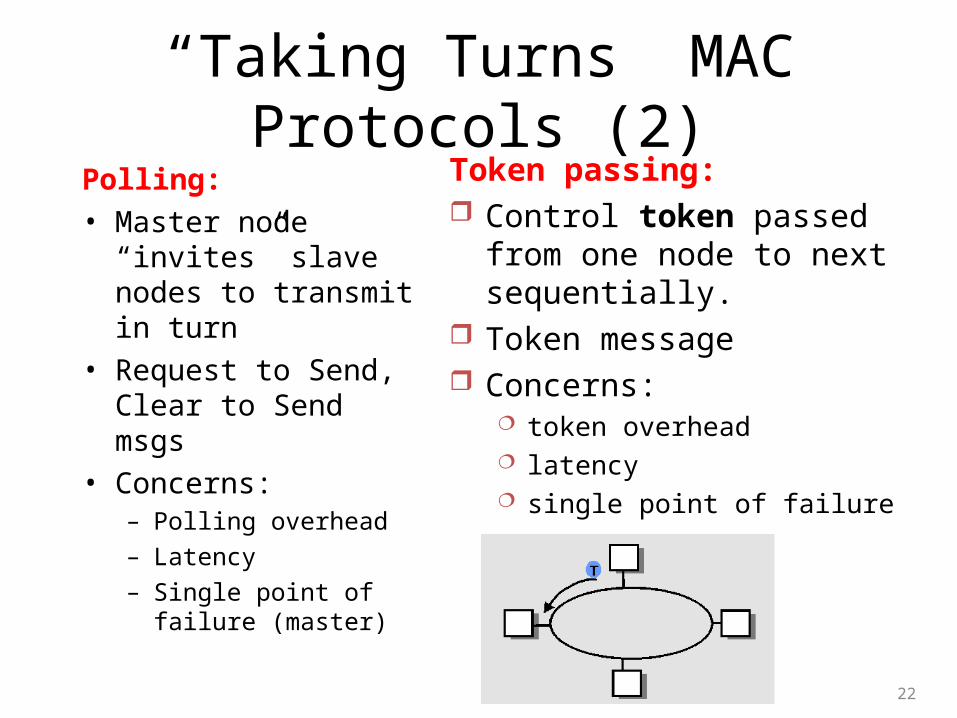
“Taking Turns” MAC Protocols (2)Polling:
• Master node “invites” slave nodes to transmit in turn
• Request to Send, Clear to Send msgs
• Concerns:– Polling overhead
– Latency
– Single point of failure (master)
22
Token passing: Control token passed from one
node to next sequentially. Token message Concerns:
token overhead latency single point of failure (token)
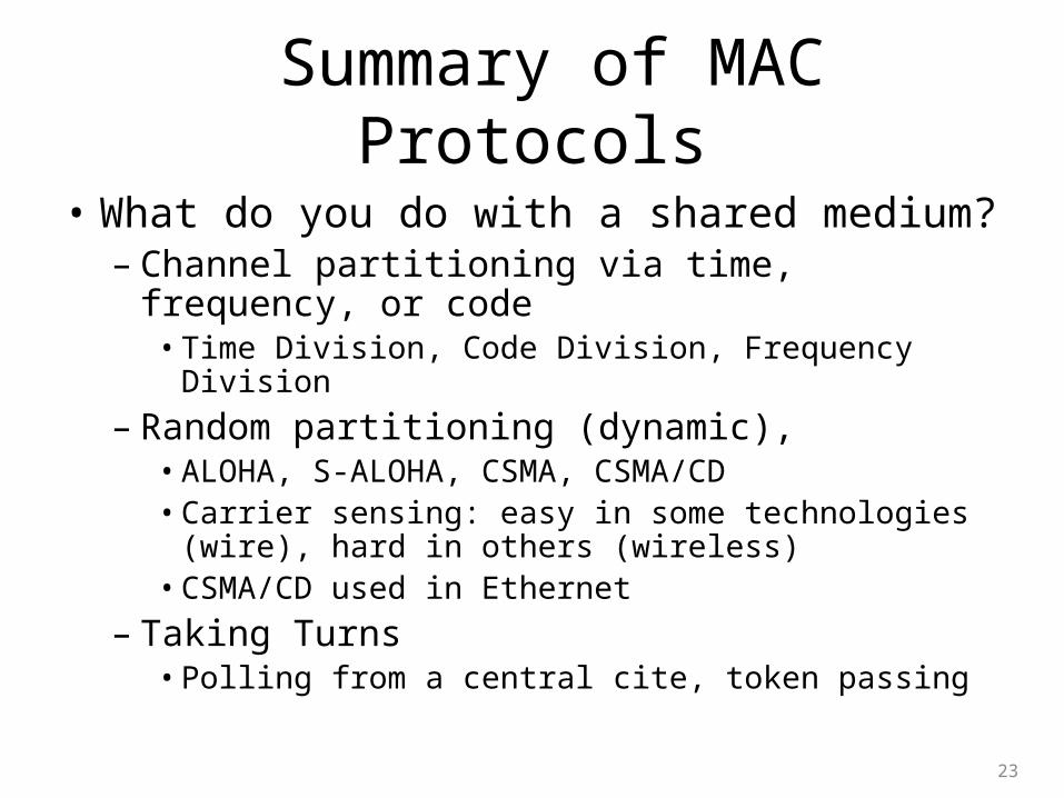
Summary of MAC Protocols
• What do you do with a shared medium?– Channel partitioning via time, frequency, or code• Time Division, Code Division, Frequency Division
– Random partitioning (dynamic), • ALOHA, S-ALOHA, CSMA, CSMA/CD• Carrier sensing: easy in some technologies (wire), hard
in others (wireless)• CSMA/CD used in Ethernet
– Taking Turns• Polling from a central cite, token passing
23
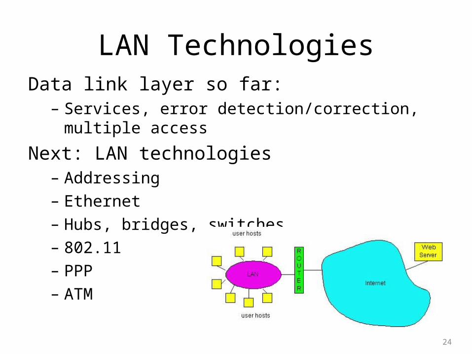
LAN TechnologiesData link layer so far:– Services, error detection/correction, multiple access
Next: LAN technologies– Addressing
– Ethernet
– Hubs, bridges, switches
– 802.11
– PPP
– ATM
24
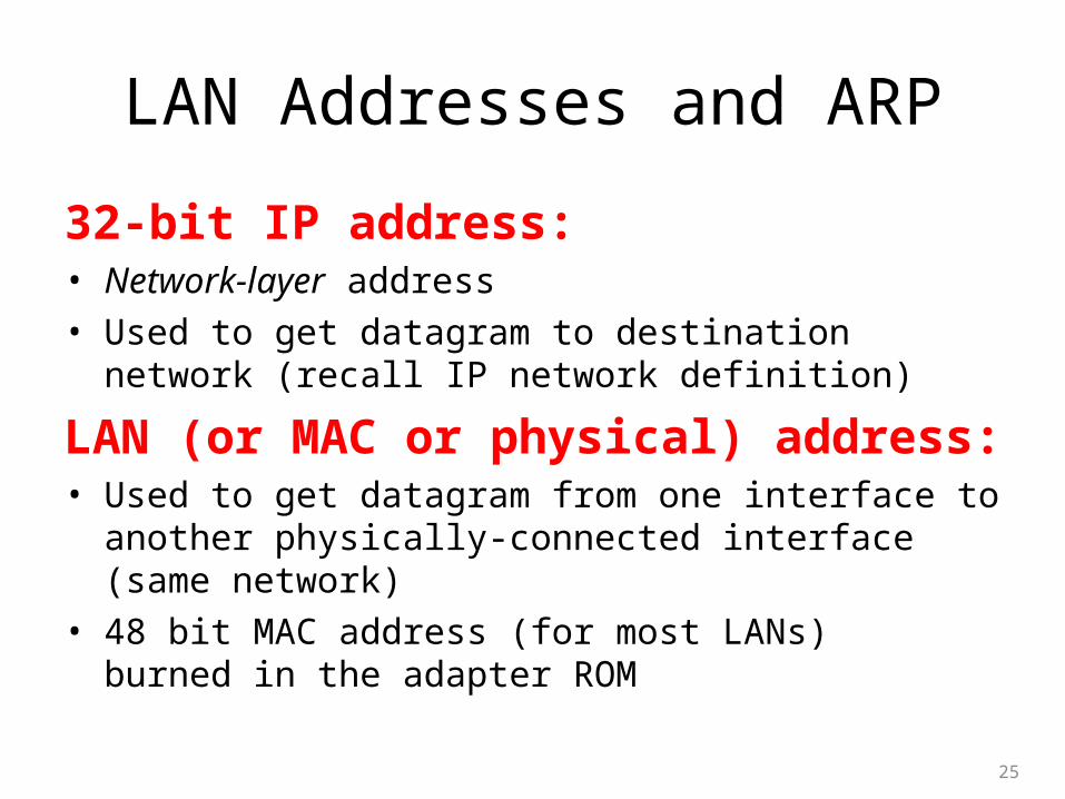
LAN Addresses and ARP
32-bit IP address: • Network-layer address
• Used to get datagram to destination network (recall IP network definition)
LAN (or MAC or physical) address: • Used to get datagram from one interface to another physically-
connected interface (same network)
• 48 bit MAC address (for most LANs) burned in the adapter ROM
25
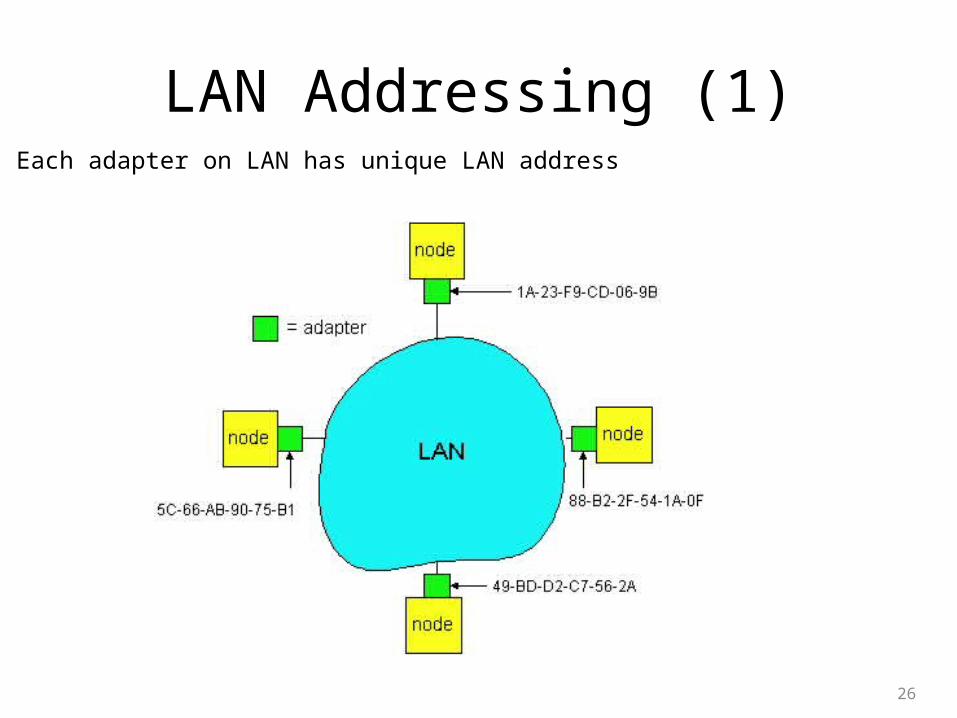
LAN Addressing (1)
26
Each adapter on LAN has unique LAN address
LAN Addressing (2)
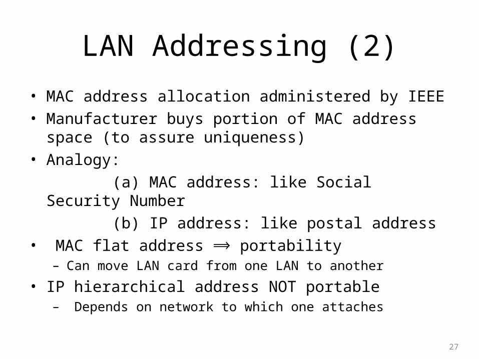
• MAC address allocation administered by IEEE
• Manufacturer buys portion of MAC address space (to assure uniqueness)
• Analogy:
(a) MAC address: like Social Security Number
(b) IP address: like postal address
• MAC flat address portability ⟹– Can move LAN card from one LAN to another
• IP hierarchical address NOT portable– Depends on network to which one attaches
27
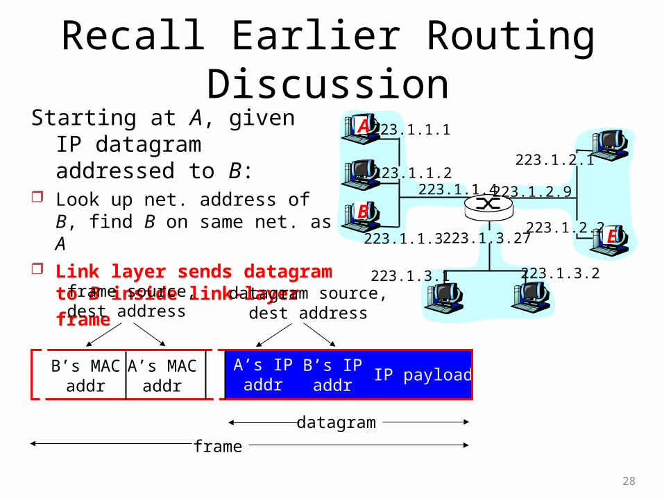
Recall Earlier Routing Discussion
28
223.1.1.1
223.1.1.2
223.1.1.3
223.1.1.4 223.1.2.9
223.1.2.2
223.1.2.1
223.1.3.2223.1.3.1
223.1.3.27
A
BE
Starting at A, given IP datagram addressed to B:
Look up net. address of B, find B on same net. as A
Link layer sends datagram to B
inside link-layer frame
B’s MACaddr
A’s MACaddr
A’s IPaddr
B’s IPaddr
IP payload
datagram
frame
frame source,dest address
datagram source,dest address
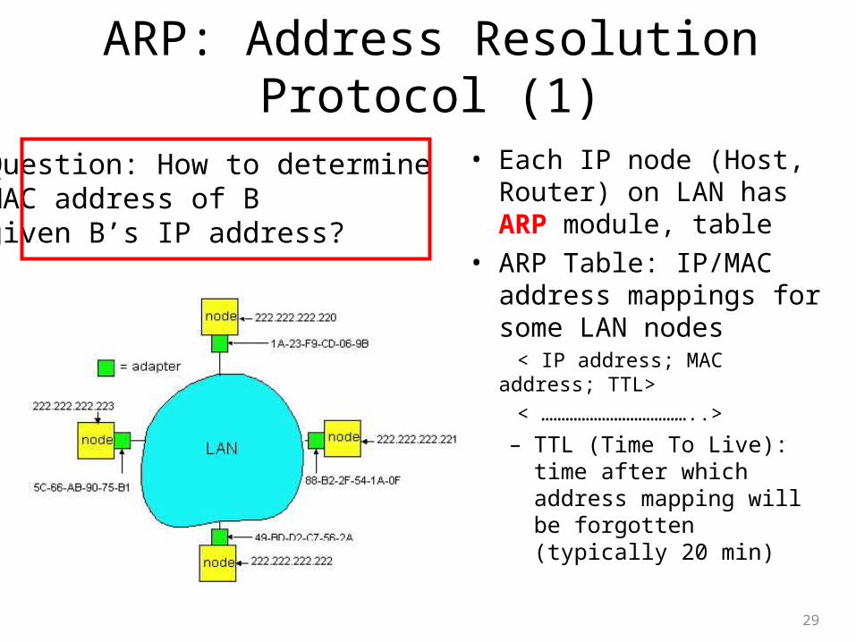
ARP: Address Resolution Protocol (1)
• Each IP node (Host, Router) on LAN has ARP module, table
• ARP Table: IP/MAC address mappings for some LAN nodes
< IP address; MAC address; TTL>
< ………………………………..>
– TTL (Time To Live): time after which address mapping will be forgotten (typically 20 min)
29
Question: How to determineMAC address of Bgiven B’s IP address?
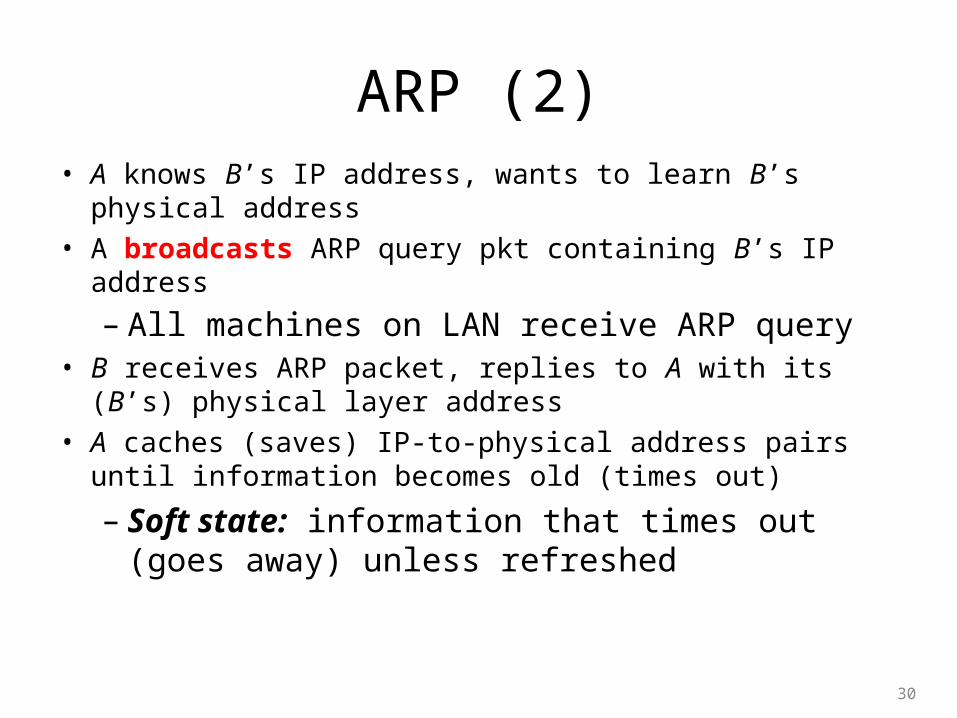
ARP (2)• A knows B’s IP address, wants to learn B’s physical
address
• A broadcasts ARP query pkt containing B’s IP address
– All machines on LAN receive ARP query
• B receives ARP packet, replies to A with its (B’s) physical layer address
• A caches (saves) IP-to-physical address pairs until information becomes old (times out)
– Soft state: information that times out (goes away) unless refreshed
30
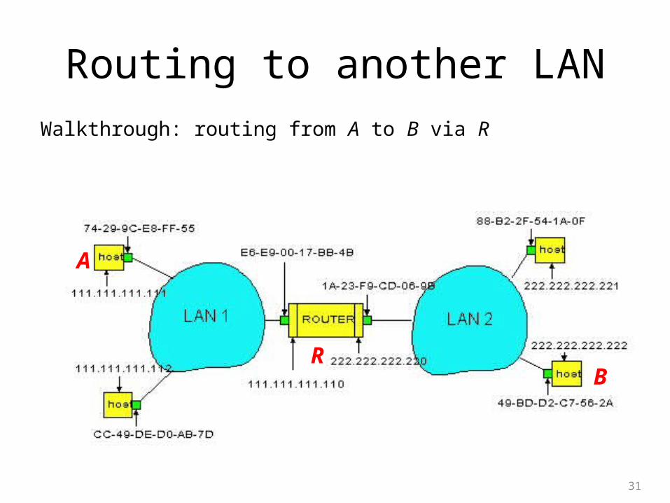
Routing to another LAN
Walkthrough: routing from A to B via R
• In routing table at source Host, find router 111.111.111.110• In ARP table at source, find MAC address E6-E9-00-17-BB-4B, etc
31
A
RB
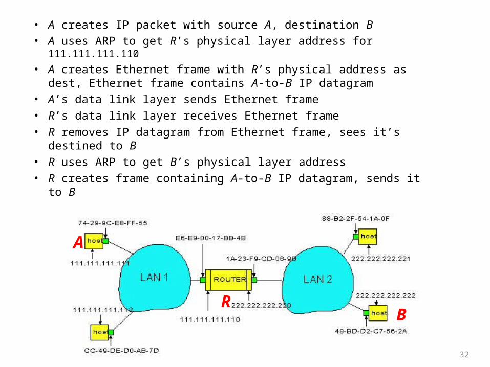
• A creates IP packet with source A, destination B • A uses ARP to get R’s physical layer address for 111.111.111.110
• A creates Ethernet frame with R’s physical address as dest, Ethernet frame contains A-to-B IP datagram
• A’s data link layer sends Ethernet frame
• R’s data link layer receives Ethernet frame
• R removes IP datagram from Ethernet frame, sees it’s destined to B
• R uses ARP to get B’s physical layer address
• R creates frame containing A-to-B IP datagram, sends it to B
32
A
RB
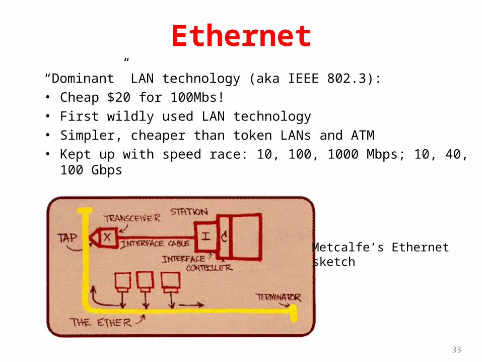
Ethernet“Dominant” LAN technology (aka IEEE 802.3):
• Cheap $20 for 100Mbs!
• First wildly used LAN technology
• Simpler, cheaper than token LANs and ATM
• Kept up with speed race: 10, 100, 1000 Mbps; 10, 40, 100 Gbps
33
Metcalfe’s Ethernetsketch
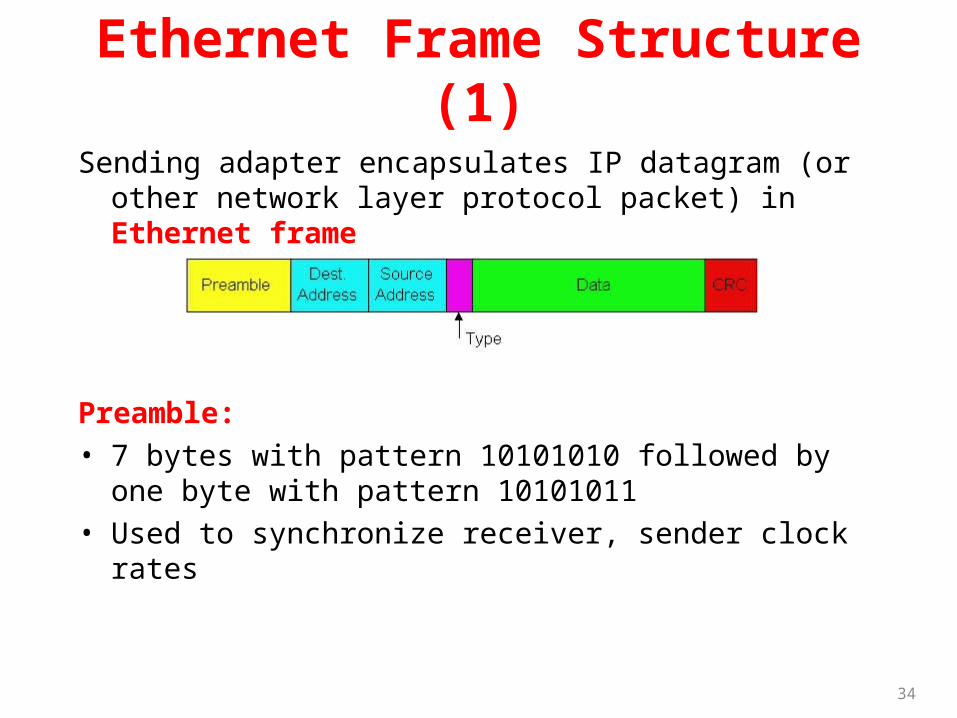
Ethernet Frame Structure (1)
Sending adapter encapsulates IP datagram (or other network layer protocol packet) in Ethernet frame
Preamble:
• 7 bytes with pattern 10101010 followed by one byte with pattern 10101011
• Used to synchronize receiver, sender clock rates
34
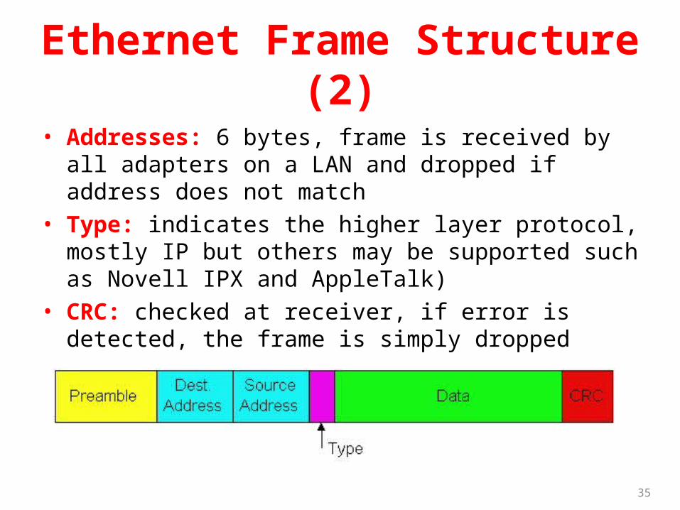
Ethernet Frame Structure (2)
• Addresses: 6 bytes, frame is received by all adapters on a LAN and dropped if address does not match
• Type: indicates the higher layer protocol, mostly IP but others may be supported such as Novell IPX and AppleTalk)
• CRC: checked at receiver, if error is detected, the frame is simply dropped
35
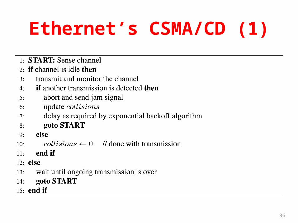
Ethernet’s CSMA/CD (1)
36
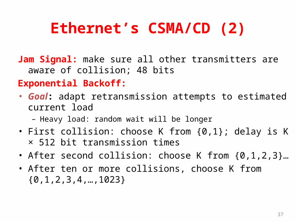
Ethernet’s CSMA/CD (2)
Jam Signal: make sure all other transmitters are aware of collision; 48 bits
Exponential Backoff:
• Goal: adapt retransmission attempts to estimated current load– Heavy load: random wait will be longer
• First collision: choose K from {0,1}; delay is K × 512 bit transmission times
• After second collision: choose K from {0,1,2,3}…
• After ten or more collisions, choose K from {0,1,2,3,4,…,1023}
37
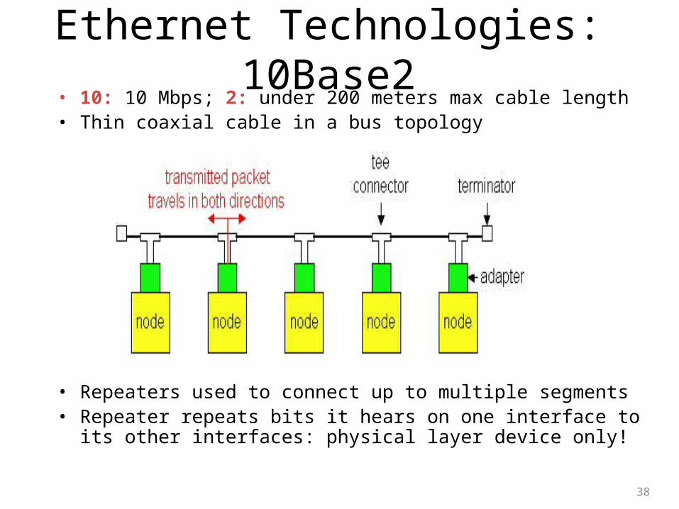
Ethernet Technologies: 10Base2• 10: 10 Mbps; 2: under 200 meters max cable length• Thin coaxial cable in a bus topology
• Repeaters used to connect up to multiple segments• Repeater repeats bits it hears on one interface to its other
interfaces: physical layer device only!
38
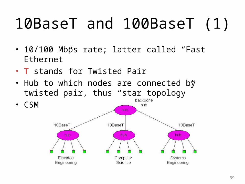
10BaseT and 100BaseT (1)
• 10/100 Mbps rate; latter called “Fast Ethernet”
• T stands for Twisted Pair
• Hub to which nodes are connected by twisted pair, thus “star topology”
• CSMA/CD implemented at hub
39
10BaseT and 100BaseT (2)
• Max distance from node to Hub is 100 meters
• Hub can disconnect “jabbering adapter”
• Hub can gather monitoring information, statistics for display to LAN administrators
40
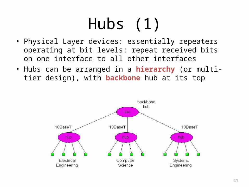
Hubs (1)• Physical Layer devices: essentially repeaters operating at
bit levels: repeat received bits on one interface to all other interfaces
• Hubs can be arranged in a hierarchy (or multi-tier design), with backbone hub at its top
41
Hubs (2)
• Each connected LAN referred to as LAN segment
• Hubs do not isolate collision domains: node may collide with any node residing at any segment in LAN
• Hub Advantages:
– Simple, inexpensive device
– Multi-tier provides graceful degradation: portions of the LAN continue to operate if one hub malfunctions
– Extends maximum distance between node pairs (100 m per hub)
42
Hub Limitations
• Single collision domain results in no increase in max throughput– Multi-tier throughput same as single segment throughput
• Individual LAN restrictions pose limits on number of nodes in same collision domain and on total allowed geographical coverage
• Cannot connect different Ethernet types (e.g., 10BaseT and 100baseT)
43
Ethernet Switch• Link-layer device: takes an active role– Store, forward Ethernet frames
– Examine incoming frame’s MAC address, selectively forward frame to one-or-more outgoing links when frame is to be forwarded on segment, uses CSMA/CD to access segment
• Transparent– Hosts are unaware of presence of switches
• Plug-and-play, self-learning– Switches do not need to be configured
44
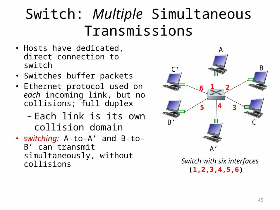
Switch: Multiple Simultaneous Transmissions
• Hosts have dedicated, direct connection to switch
• Switches buffer packets• Ethernet protocol used on each
incoming link, but no collisions; full duplex
– Each link is its own collision domain
• switching: A-to-A’ and B-to-B’ can transmit simultaneously, without collisions Switch with six interfaces
(1,2,3,4,5,6)
A
A’
B
B’ C
C’
1 2
345
6
45
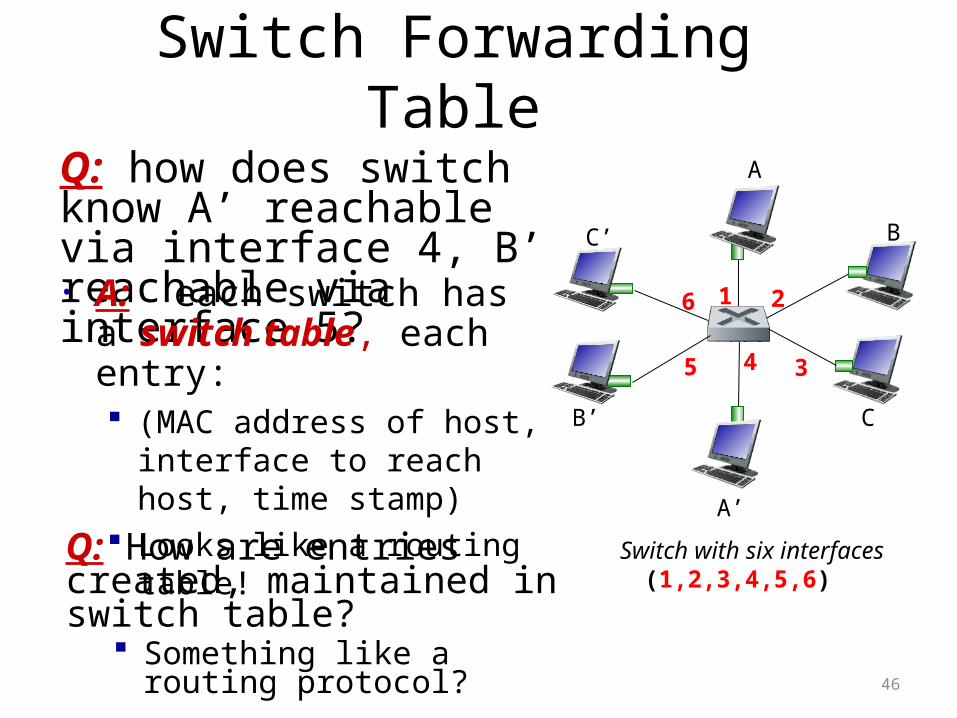
Switch Forwarding Table
Q: how does switch know A’ reachable via interface 4, B’ reachable via interface 5?
Switch with six interfaces(1,2,3,4,5,6)
A
A’
B
B’ C
C’
1 2
345
6• A: each switch has a switch table, each entry: (MAC address of host, interface
to reach host, time stamp) Looks like a routing table!
Q: How are entries created, maintained in switch table?
Something like a routing protocol?
46
A
A’
B
B’ C
C’
1 2
345
6
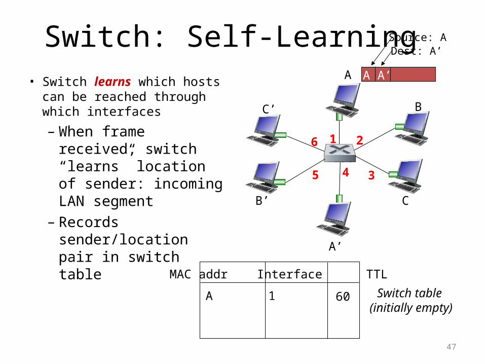
Switch: Self-Learning• Switch learns which hosts can
be reached through which interfaces
– When frame received, switch “learns” location of sender: incoming LAN segment
– Records sender/location pair in switch table
A A’
Source: ADest: A’
MAC addr Interface TTL
Switch table (initially empty)
A 1 60
47
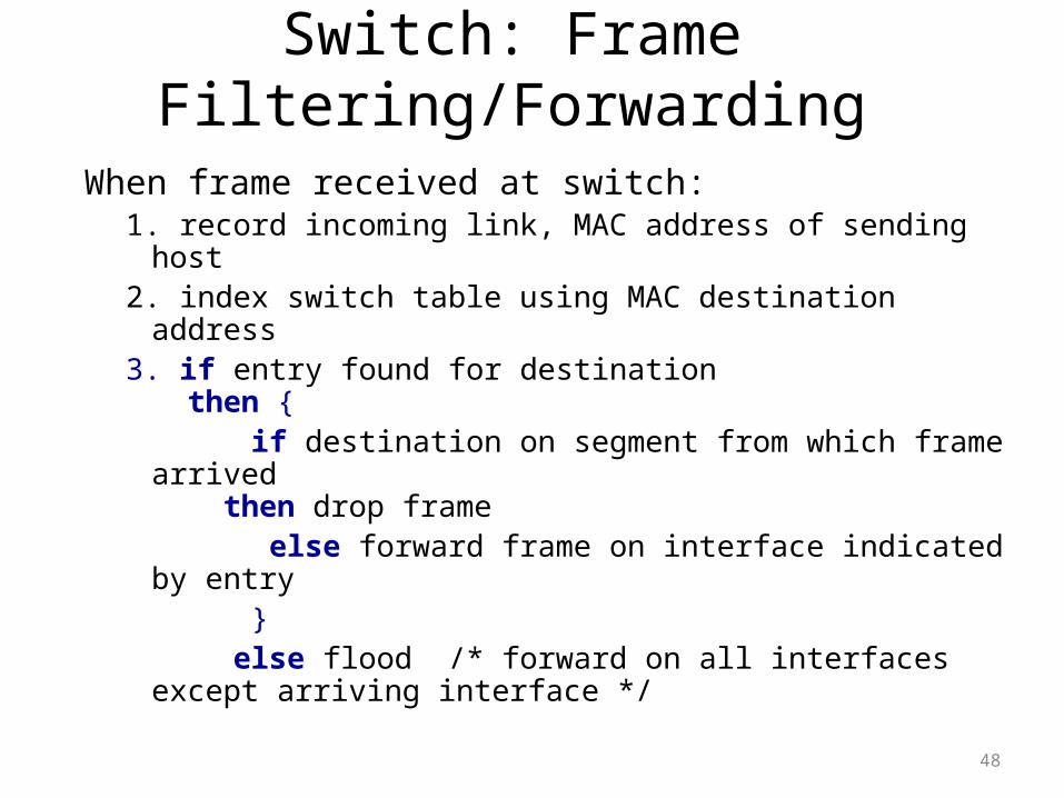
Switch: Frame Filtering/Forwarding
When frame received at switch:1. record incoming link, MAC address of sending host2. index switch table using MAC destination address3. if entry found for destination
then { if destination on segment from which frame arrived
then drop frame else forward frame on interface indicated by entry } else flood /* forward on all interfaces except
arriving interface */
48
A
A’
B
B’ C
C’
1 2
345
6
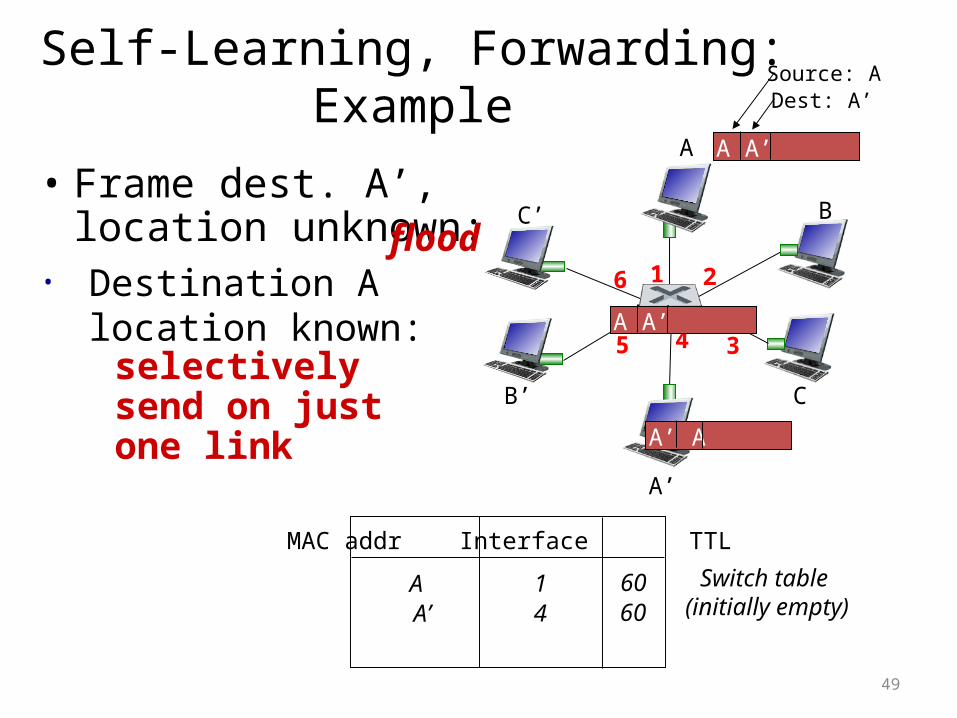
Self-Learning, Forwarding: ExampleA A’
Source: ADest: A’
MAC addr Interface TTL
Switch table (initially empty)
A 1 60
A A’A A’A A’A A’A A’
• Frame dest. A’, location unknown: flood
A’ A
• Destination A location known:
A’ 4 60
selectively send on just one link
49
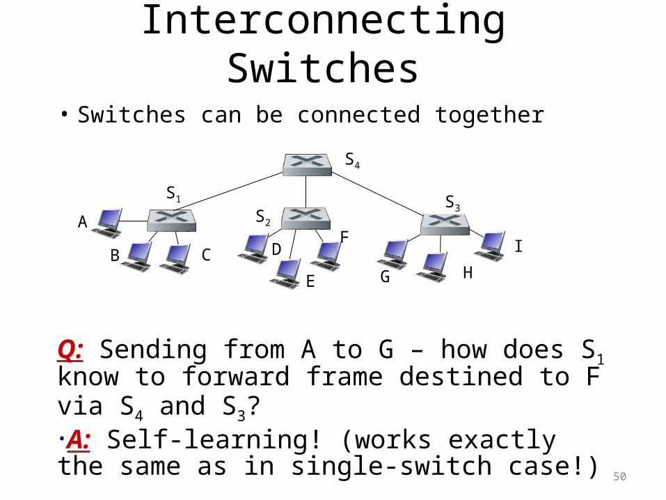
Interconnecting Switches
• Switches can be connected together
Q: Sending from A to G – how does S1 know to forward frame destined to F via S4 and S3?•A: Self-learning! (works exactly the same as in single-switch case!)
A
B
S1
C D
E
FS2
S4
S3
H
I
G
50
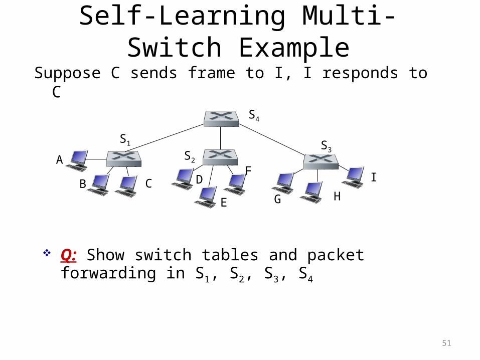
Self-Learning Multi-Switch Example
Suppose C sends frame to I, I responds to C
Q: Show switch tables and packet forwarding in S1, S2, S3, S4
A
B
S1
C D
E
FS2
S4
S3
H
I
G
51
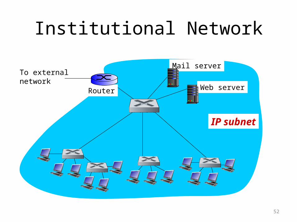
Institutional Network
To externalnetwork
Router
IP subnet
Mail server
Web server
52
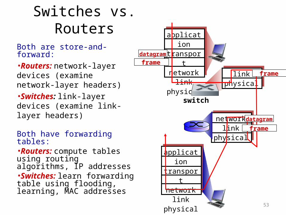
Switches vs. Routers
Both are store-and-forward:
•Routers: network-layer devices (examine network-layer headers)
•Switches: link-layer devices (examine link-layer headers)
Both have forwarding tables:•Routers: compute tables using routing algorithms, IP addresses•Switches: learn forwarding table using flooding, learning, MAC addresses
applicationtransportnetwork
linkphysical
networklink
physical
linkphysical
switch
datagram
applicationtransportnetwork
linkphysical
frame
frame
frame
datagram
53
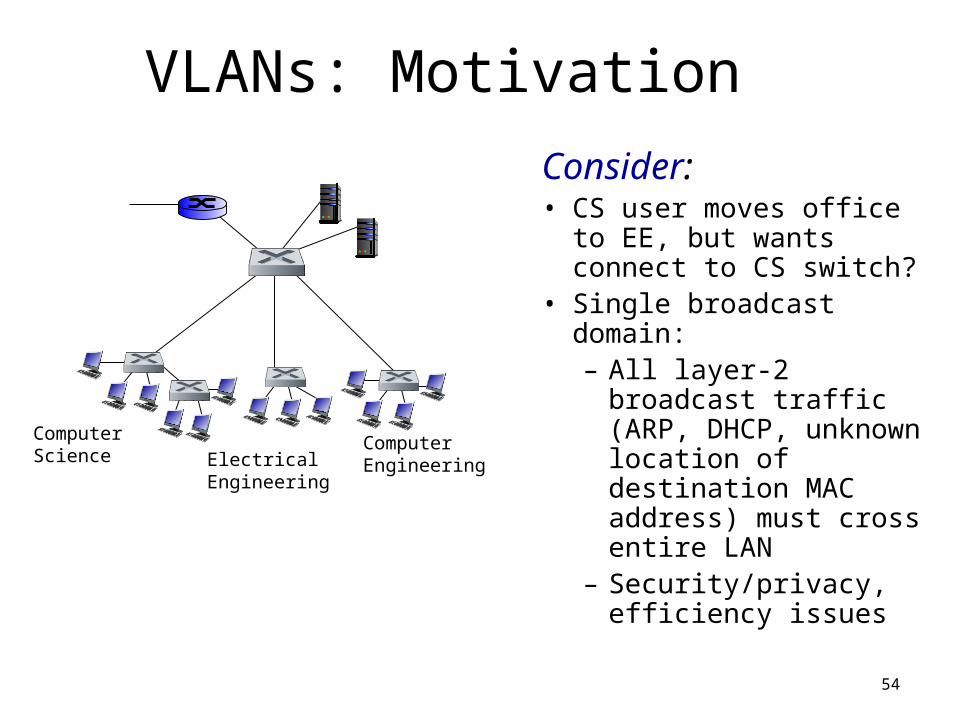
VLANs: Motivation
Consider:• CS user moves office to
EE, but wants connect to CS switch?
• Single broadcast domain:– All layer-2 broadcast
traffic (ARP, DHCP, unknown location of destination MAC address) must cross entire LAN
– Security/privacy, efficiency issues
54
Computer Science Electrical
Engineering
ComputerEngineering
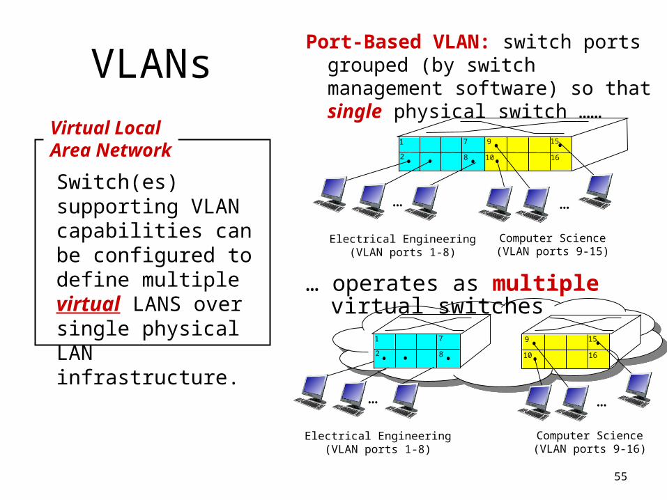
VLANsPort-Based VLAN: switch ports
grouped (by switch management software) so that single physical switch ……
55
Switch(es) supporting VLAN capabilities can be configured to define multiple virtual LANS over single physical LAN infrastructure.
Virtual Local Area Network
1
8
9
16102
7
…
Electrical Engineering(VLAN ports 1-8)
Computer Science(VLAN ports 9-15)
15
…
Electrical Engineering(VLAN ports 1-8)
…
1
82
7 9
1610
15
…
Computer Science(VLAN ports 9-16)
… operates as multiple virtual switches
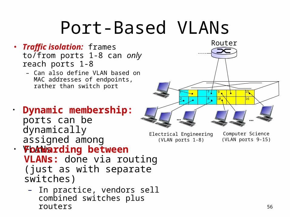
Port-Based VLANs• Traffic isolation: frames to/from
ports 1-8 can only reach ports 1-8– Can also define VLAN based on
MAC addresses of endpoints, rather than switch port
56
1
8
9
16102
7
…
Electrical Engineering(VLAN ports 1-8)
Computer Science(VLAN ports 9-15)
15
…• Dynamic membership:
ports can be dynamically assigned among VLANs
Router
• Forwarding between VLANs: done via routing (just as with separate switches)– In practice, vendors sell combined
switches plus routers
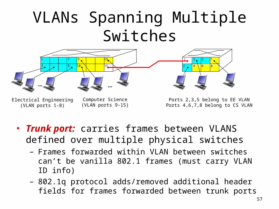
VLANs Spanning Multiple Switches
• Trunk port: carries frames between VLANS defined over multiple physical switches– Frames forwarded within VLAN between switches can’t be vanilla
802.1 frames (must carry VLAN ID info)
– 802.1q protocol adds/removed additional header fields for frames forwarded between trunk ports
57
1
8
9
102
7
…
Electrical Engineering(VLAN ports 1-8)
Computer Science(VLAN ports 9-15)
15
…
2
73
Ports 2,3,5 belong to EE VLANPorts 4,6,7,8 belong to CS VLAN
5
4 6 816
1
58
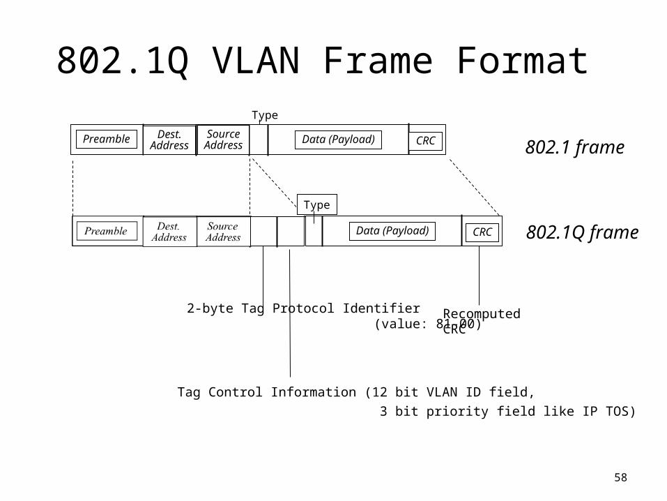
Type
2-byte Tag Protocol Identifier (value: 81-00)
Tag Control Information (12 bit VLAN ID field,
3 bit priority field like IP TOS)
Recomputed CRC
802.1Q VLAN Frame Format
802.1 frame
802.1Q frame
Dest.Address
SourceAddress Data (Payload) CRCPreamble
Data (Payload) CRC
Type
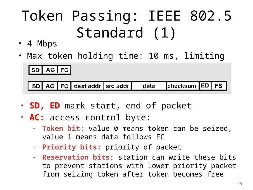
Token Passing: IEEE 802.5 Standard (1)• 4 Mbps
• Max token holding time: 10 ms, limiting frame length
59
• SD, ED mark start, end of packet • AC: access control byte:
– Token bit: value 0 means token can be seized, value 1 means data follows FC
– Priority bits: priority of packet – Reservation bits: station can write these bits to prevent stations with
lower priority packet from seizing token after token becomes free
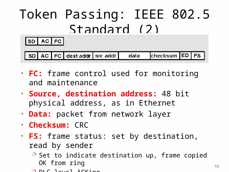
Token Passing: IEEE 802.5 Standard (2)
60
• FC: frame control used for monitoring and maintenance • Source, destination address: 48 bit physical address, as in
Ethernet • Data: packet from network layer • Checksum: CRC • FS: frame status: set by destination, read by sender
Set to indicate destination up, frame copied OK from ring DLC-level ACKing
Interconnecting LANs
Q: Why not just one big LAN? • Limited amount of supportable traffic: on single LAN, all
stations must share bandwidth
• Limited length: 802.3 specifies maximum cable length
• Large “collision domain” (can collide with many stations)
• Limited number of stations: 802.5 have token passing delays at each station
61
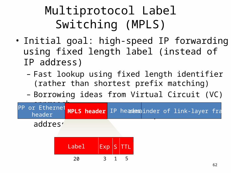
Multiprotocol Label Switching (MPLS)
• Initial goal: high-speed IP forwarding using fixed length label (instead of IP address) – Fast lookup using fixed length identifier (rather than shortest
prefix matching)
– Borrowing ideas from Virtual Circuit (VC) approach
– But IP datagrams still keep their IP addresses!
62
PPP or Ethernet header
IP header remainder of link-layer frameMPLS header
Label Exp S TTL
20 3 1 5
MPLS-Capable Routers
• A.k.a. label-switched router• Forward packets to outgoing interface based only
on label value (don’t inspect IP address)– MPLS forwarding table distinct from IP forwarding
tables• Flexibility: MPLS forwarding decisions can differ
from those of IP– Use destination and source addresses to route flows to
same destination differently (traffic engineering)– Re-route flows quickly if link fails: pre-computed
backup paths (useful for VoIP)
63
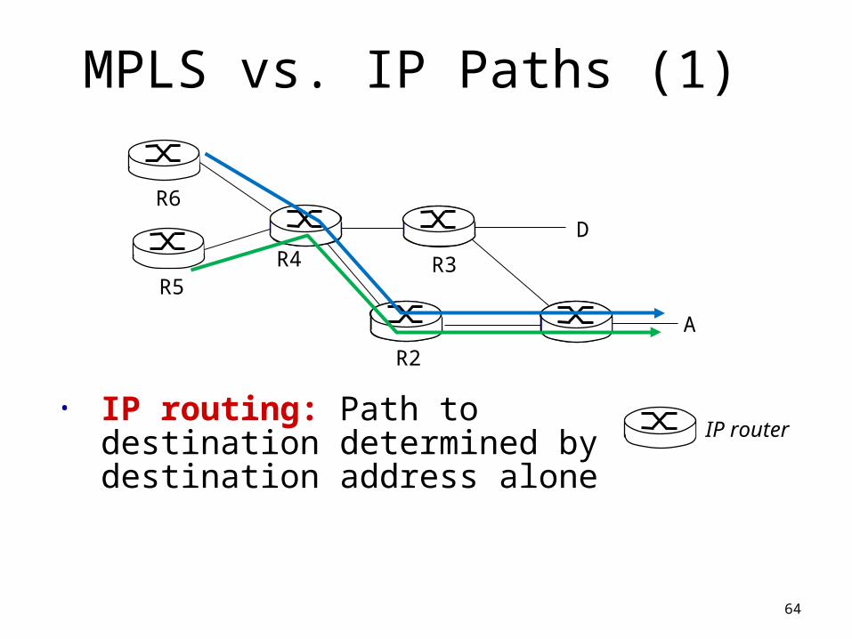
MPLS vs. IP Paths (1)
64
R2
D
R3R5
A
R6
IP router• IP routing: Path to destination
determined by destination address alone
R4
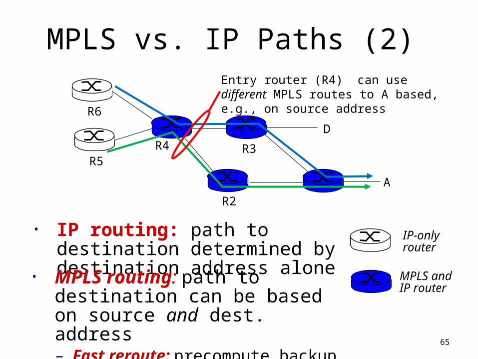
MPLS vs. IP Paths (2)
65
R2
D
R3R4R5
A
R6
IP-onlyrouter
• IP routing: path to destination determined by destination address alone
MPLS and IP router
• MPLS routing: path to destination can be based on source and dest. address– Fast reroute: precompute backup routes
in case of link failure
Entry router (R4) can use different MPLS routes to A based, e.g., on source address
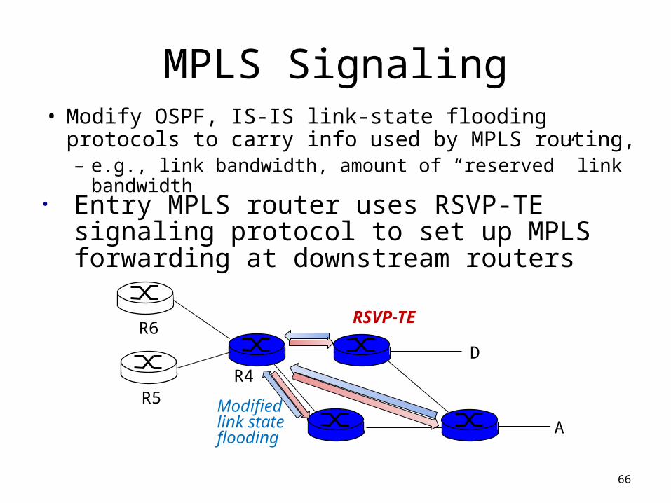
MPLS Signaling• Modify OSPF, IS-IS link-state flooding protocols to
carry info used by MPLS routing, – e.g., link bandwidth, amount of “reserved” link bandwidth
66
DR4
R5
A
R6
• Entry MPLS router uses RSVP-TE signaling protocol to set up MPLS forwarding at downstream routers
Modified link state flooding
RSVP-TE
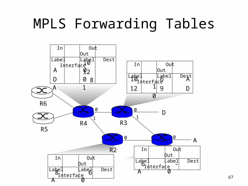
MPLS Forwarding Tables
67
R1R2
D
R3R4R5
0
1
00
A
R6
In Out OutLabel Label Dest Interface
6 - A 0
In Out OutLabel Label Dest Interface
10 6 A 1
12 9 D 0
In Out OutLabel Label Dest Interface
10 A 0
12 D 0
1
In Out OutLabel Label Dest Interface
8 6 A 0
0
8 A 1
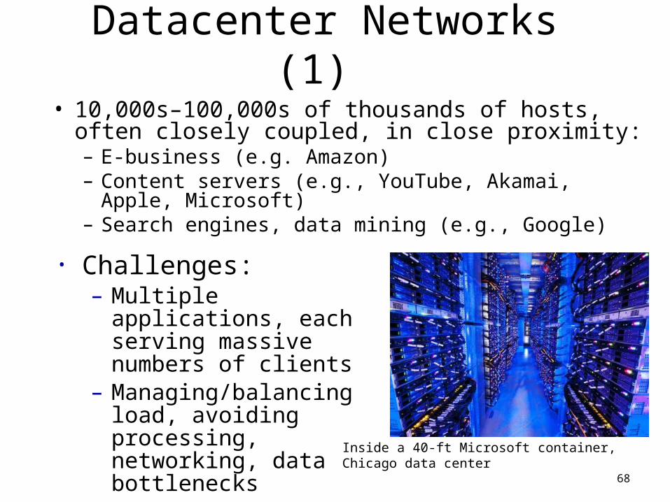
Datacenter Networks (1)
• 10,000s–100,000s of thousands of hosts, often closely coupled, in close proximity:– E-business (e.g. Amazon)– Content servers (e.g., YouTube, Akamai, Apple, Microsoft)– Search engines, data mining (e.g., Google)
68
• Challenges:– Multiple applications, each
serving massive numbers of clients
– Managing/balancing load, avoiding processing, networking, data bottlenecks
Inside a 40-ft Microsoft container, Chicago data center
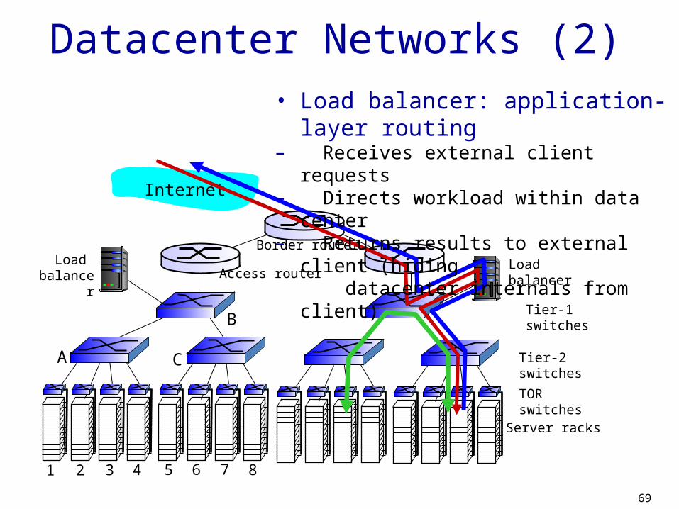
69
Server racks
TOR switches
Tier-1 switches
Tier-2 switches
Load balancer
Load balancer
B
1 2 3 4 5 6 7 8
A C
Border router
Access router
Internet
Datacenter Networks (2)• Load balancer: application-layer routing– Receives external client requests– Directs workload within data center– Returns results to external client (hiding
datacenter internals from client)
Server racks
TOR switches
Tier-1 switches
Tier-2 switches
1 2 3 4 5 6 7 8
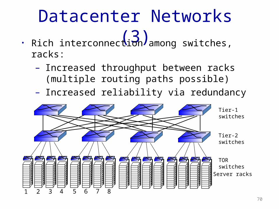
Datacenter Networks (3)• Rich interconnection among switches, racks:
– Increased throughput between racks (multiple routing paths possible)
– Increased reliability via redundancy
70
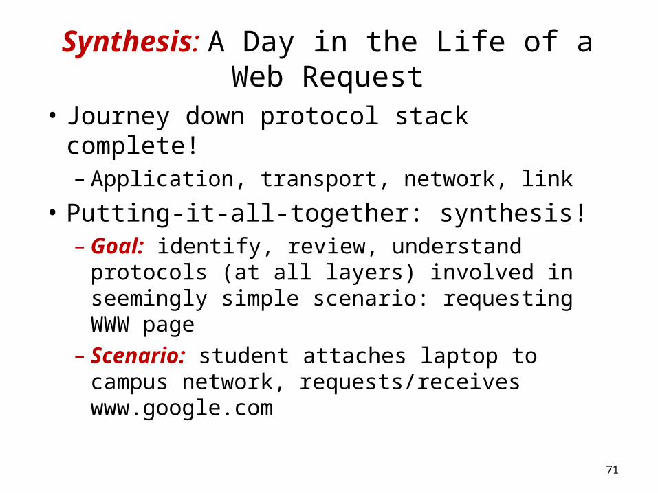
Synthesis: A Day in the Life of a Web Request
• Journey down protocol stack complete!– Application, transport, network, link
• Putting-it-all-together: synthesis!– Goal: identify, review, understand protocols (at
all layers) involved in seemingly simple scenario: requesting WWW page
– Scenario: student attaches laptop to campus network, requests/receives www.google.com
71
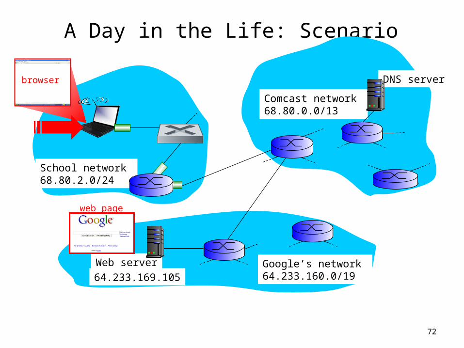
A Day in the Life: Scenario
72
Comcast network 68.80.0.0/13
Google’s network 64.233.160.0/19 64.233.169.105
Web server
DNS server
School network 68.80.2.0/24
web page
browser
Router(Runs DHCP)
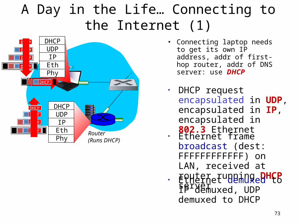
A Day in the Life… Connecting to the Internet (1)
• Connecting laptop needs to get its own IP address, addr of first-hop router, addr of DNS server: use DHCP
73
DHCPUDP
IPEthPhy
DHCP
DHCP
DHCP
DHCP
DHCP
DHCPUDP
IPEthPhy
DHCP
DHCP
DHCP
DHCPDHCP
• DHCP request encapsulated in UDP, encapsulated in IP, encapsulated in 802.3 Ethernet
• Ethernet frame broadcast (dest: FFFFFFFFFFFF) on LAN, received at router running DHCP server
• Ethernet demuxed to IP demuxed, UDP demuxed to DHCP
Router(runs DHCP)
A Day in the Life… Connecting to the Internet (2)
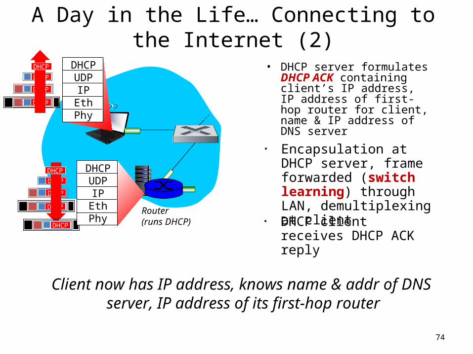
• DHCP server formulates DHCP ACK containing client’s IP address, IP address of first-hop router for client, name & IP address of DNS server
74
DHCPUDP
IPEthPhy
DHCP
DHCP
DHCP
DHCP
DHCPUDP
IPEthPhy
DHCP
DHCP
DHCP
DHCP
DHCP
• Encapsulation at DHCP server, frame forwarded (switch learning) through LAN, demultiplexing at client
Client now has IP address, knows name & addr of DNS server, IP address of its first-hop router
• DHCP client receives DHCP ACK reply
Router(runs DHCP)
A Day in the Life… ARP (Before DNS, HTTP)
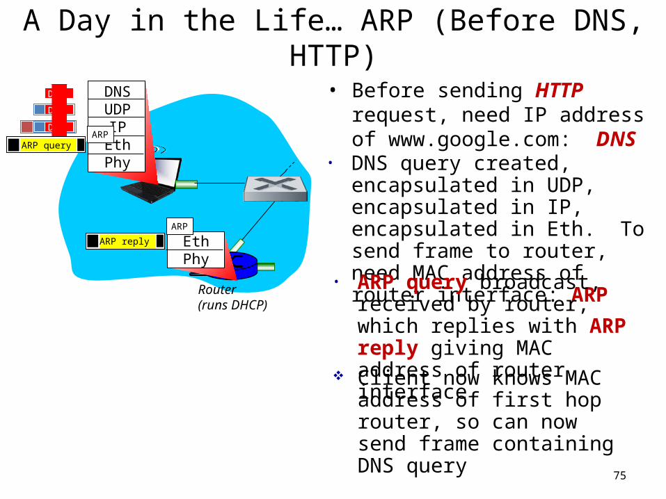
• Before sending HTTP request, need IP address of www.google.com: DNS
75
DNSUDP
IPEthPhy
DNS
DNS
DNS
• DNS query created, encapsulated in UDP, encapsulated in IP, encapsulated in Eth. To send frame to router, need MAC address of router interface: ARP
• ARP query broadcast, received by router, which replies with ARP reply giving MAC address of router interface
Client now knows MAC address of first hop router, so can now send frame containing DNS query
ARP query
EthPhy
ARP
ARP
ARP reply
Router(runs DHCP)
A Day in the Life… Using DNS
76
DNSUDP
IPEthPhy
DNS
DNS
DNS
DNS
DNS
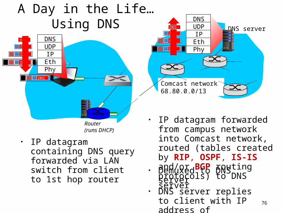
• IP datagram containing DNS query forwarded via LAN switch from client to 1st hop router
• IP datagram forwarded from campus network into Comcast network, routed (tables created by RIP, OSPF, IS-IS and/or BGP routing protocols) to DNS server
• Demuxed to DNS server• DNS server replies to client
with IP address of www.google.com
Comcast network 68.80.0.0/13
DNS server
DNSUDP
IPEthPhy
DNS
DNS
DNS
DNS
Router(runs DHCP)
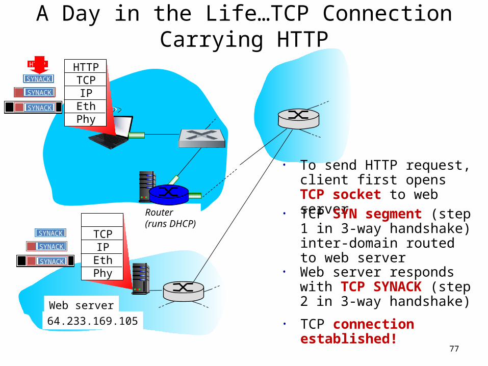
A Day in the Life…TCP Connection Carrying HTTP
77
HTTPTCPIP
EthPhy
HTTP
• To send HTTP request, client first opens TCP socket to web server
• TCP SYN segment (step 1 in 3-way handshake) inter-domain routed to web server
• TCP connection established!64.233.169.105
Web server
SYN
SYN
SYN
SYN
TCPIP
EthPhy
SYN
SYN
SYN
SYNACK
SYNACK
SYNACK
SYNACK
SYNACK
SYNACK
SYNACK
• Web server responds with TCP SYNACK (step 2 in 3-way handshake)
Router(runs DHCP)
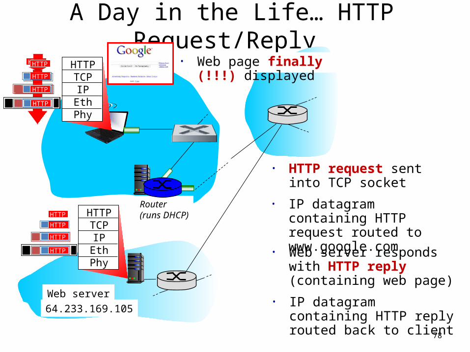
A Day in the Life… HTTP Request/Reply
78
HTTPTCPIP
EthPhy
HTTP
• HTTP request sent into TCP socket
• IP datagram containing HTTP request routed to www.google.com
• IP datagram containing HTTP reply routed back to client
64.233.169.105
Web server
HTTPTCPIP
EthPhy
• Web server responds with HTTP reply (containing web page)
HTTP
HTTP
HTTPHTTP
HTTP
HTTP
HTTP
HTTP
HTTP
HTTP
HTTP
HTTP
HTTP
• Web page finally (!!!) displayed
Part 5: Summary• Principles behind data link layer services:
– Error detection, correction– Sharing a broadcast channel: multiple access– Link layer addressing, ARP
• Various link layer technologies– Ethernet– hubs, bridges, switches– IEEE 802.11 LANs– PPP– ATM– X.25, Frame Relay– MPLS– Datacenter Networking
• Journey down the protocol stack now OVER!
79