Embed Size (px)
Citation preview

Intersection-free Contouring on An Octree Grid
Tao JuWashington University in St. Louis
One Brookings DriveSt. Louis, MO 63130, USA
Tushar UdeshiZyvex Corporation
1321 North Plano RoadRichardson, Texas 75081-2426, USA
Abstract
A method for extracting intersection-free iso-surfacesfrom volumetric data with an octree structure is presented.Unlike contouring techniques designed for uniform grids(such as Marching Cubes), adaptive contouring methods(such as Dual Contouring) can and do often generate inter-secting polygons. Our main contribution is a polygon gen-eration algorithm that produces triangles enclosed in non-overlapping volumes, which guarantees an intersection-freemesh. Like other adaptive contouring methods, this newmethod generates crack-free and feature-preserving sur-faces on both uniform and octree grids. We demonstratethe method on both scanned objects and industrial models.
1. Introduction
Contouring is the process of extracting iso-surfaces fromvolumetric data. Many applications, such as Finite ElementAnalysis, require their input surface to be a closed meshwith no intersecting polygons. Traditional contouring tech-niques, such as the Marching Cubes [13] method and itsvariations [4, 2, 15, 12], fulfill this requirement because theygenerate triangles enclosed in grid cells and, within eachcell, the triangles are not intersecting. However, these meth-ods are typically confined to a uniform grid structure andthe resulting mesh size may become prohibitive for largevolumes.
Dual Contouring, introduced by Ju et al. [11], is de-signed for extracting iso-surfaces with adaptive resolution.By extending the polygon generation scheme proposed inSurfaceNet [7] from a uniform grid onto an octree, DualContouring generates crack-free contours in an adaptivemanner. In addition, DC is capable of reproducing sharpgeometry features when Hermite data is available.
Unfortunately, unlike Marching Cubes, a polygon gen-erated by Dual Contouring is not contained in a grid cell,and hence guaranteeing intersecting-free surfaces becomes
Figure 1. Adaptive contouring of the Actua-tor Pads model using Dual Contouring (top),which contains self-intersections (shown onright), and using intersection-free contouring(bottom).
difficult. In fact, we observed in our experiments that thesurface produced by Dual Contouring israrely intersection-free (an example is shown in Figure 1 (top)). Althoughsubsequent work [19, 1, 17, 20, 14] has improved upon thetopology representation in DC, the problem of geometricintersections has remained un-addressed.
Several other methods have also been proposed for adap-tive contouring [9, 3]. These methods use a polygon gener-ation technique similar to Dual Contouring, and hence theymay also produce intersecting polygons. In addition, we
12
43
5
6
7
12
7
3
5
6
4
12
7
3
5
6
4
12
34
5
67
1
2
3
45
67
1
2
3
45
67
(a) (b) (c) (d)
Figure 2. Resolving intersecting polygons on a uniform (top ) and octree (bottom) grid. (a): Signs atgrid points (black for positive and white for negative). (b, c): Non-intersecting (b) and intersecting(c) triangles generated by DC for the thickened grid edges in (a). (d): Our method resolves the self-intersections in (c) by changing the triangulation (top) an d introducing additional vertices on twogrid faces (empty squares) and a grid edge (empty circle).
note that one class of mesh-repair methods [3, 10] relieson volumetric scan-conversion and adaptive contouring tofix geometrically incorrect (e.g., self-intersecting) meshes.The effectiveness of these methods become questionableas the output of contouring may again contain new self-intersections.
1.1. Contributions
To date, we have not seen any study on the geometriccorrectness of adaptive contouring methods. In this paper,we analyze intersecting polygons created by Dual Contour-ing, and propose an intersection-free solution for adaptivecontouring. Just as Marching Cubes generates triangles en-closed in grid cells, our method creates triangles enclosedinnon-overlapping volumes, and hence avoids potential inter-sections. In particular, we make the following observationsand contributions:
• We show that the polygon generation technique inDual Contouring can, and often does, yield intersect-ing polygons on both uniform grids and octrees.
• We introduce a simple polygon generation techniquethat is guaranteed to produce intersection-free and
crack-free meshes on an octree, but at the cost of anexcessive number of output triangles.
• We improve upon the above technique by employingmultiple polygon generation rules, which dramaticallyreduces the number of output triangles while still guar-anteeing geometric correctness.
2. Primal and dual contouring
We start by investigating two competing contouringschemes. Given a uniform grid of signed scalar values, theMarching Cubes (MC) method [13] creates one vertex foreach edge on the grid that contains a sign change, which arethen connected by triangles that lie within cubic grid cells.Since the triangles within each cell are non-intersecting,andsince all cells are disjoint, the surface extracted by MC isalways intersection-free. Unfortunately, it is difficult to ex-tend MC beyond a uniform grid, because cracks may oc-cur between polygons extracted from grid cells of differentsizes.
To extract crack-free iso-surfaces on adaptive grids, DualContouring (DC) [11] extends a polygon generation methodthat was first proposed in SurfaceNet [7] on a uniform grid.

Given a signed octree grid, DC creates one vertex for eachgrid cell that contains a sign change, and builds one polygonfor each grid edge exhibiting a sign change, which connectsthe vertices of the cells sharing that edge1. The surface isguaranteed to be topologically closed as each polygon edgeis shared by an even number of polygons.2
Note that a vertex (polygon) generated by DC is topolog-ically dual to a polygon (vertex) generated by MC. Hencewe refer to MC as aprimal method, and call DC and othermethods using polygon generation mechanisms similar toDC [7, 19, 1, 14, 20, 9, 3]dual methods.
Unlike MC, the polygons generated by dual methods arenot constrained to lie within grid cells, and they may geo-metrically intersect. Figure 2 shows two examples of self-intersections resulted from applying DC on a uniform gridand on an octree.3 Notice that the same sign configurationmay yield either non-intersecting or intersecting polygons,depending on the geometric locations of the vertices withinthe grid cells.
3. A hybrid approach
We first introduce a simple, hybrid method that combinesprimal and dual contouring to generate both crack-free andintersection-free iso-surfaces on octree grids. Recall thatMC [13] generates intersection-free surfaces because thetriangles are contained within disjoint volumes (i.e., cubicgrid cells), and within each volume, the triangles do not in-tersect. In the same spirit, our hybrid approach generatestriangles contained in non-overlapping volumes, calleden-velopes, and within each envelope, triangles do not inter-sect.
As described in the previous section, a primal contour-ing method creates vertices on grid edges, whereas a dualmethod creates vertices within grid cells. In the hybridmethod, we associate oneedge vertex, face vertex, or cellvertexon each grid edge, face or cell that contains a signchange (the placement of these vertices are discussed innext section). To create the polygons, we generate a tri-angle fan for each grid edgee that contains a sign change,where each triangle connects the edge vertexve on e, theface vertexvf on a facef sharinge, and the cell vertexvc
in a cellc sharingf , as shown Figure 3 (top). Since a gridedge may be shared by 3 or 4 cells on an octree, a fan of 6or 8 triangles will be generated.
Note that each triangle fan generated by this hybridmethod is a tessellation of a polygon produced by the DC
1In our discussion, a grid edge (face) on an octree refers to a minimaledge (face) that does not contain smaller edges (faces).
2DC may produce non-manifold surfaces, which has been studied inseveral other works [1, 20, 14].
3Every quadrilateral generated by DC is split into two triangles alongan arbitrary diagonal.
evf
ve vc
vc
evf
Ee
vc vf
Figure 3. Triangle fan (top) generated by thehybrid method at a grid edge e, a single tetra-hedron (middle) and the union of all tetrahe-dra that form the envelope Ee (bottom). Cellvertices, face vertices and edge vertices aredrawn as filled circles, empty squares andempty circles.
method. Like DC, this hybrid approach generates a crack-free surface. However, unlike DC, adding extra vertices onedges and faces provides us with additional geometric free-dom to place triangles so that they do not intersect:
Proposition 1 Triangles generated by the hybrid methoddo not intersect if each cell vertex, face vertex and edgevertex lies interior to the corresponding cell, face or edge.
Proof: We define theenvelopeEe at a grid edgee as theunion of (6 or 8) tetrahedra, each formed by edgee, vertexvf on a facef sharinge, and vertexvc in a cell c sharingf . In Figure 3, we show one such tetrahedron in the middleand the union of all tetrahedra at the bottom. In particular,Ee is called avalid envelope if each face vertexvf and cellvertexvc lies interior to the facef or cell c.
We first observe that valid envelopesEe of differentedgese are disjoint. This is because different envelopes do

t1t2
e
d f
evf
(a) (b)
e
t1
e
dt’
(c) (d)
Figure 4. A trivial triangulation (a), and thepolygon-edge intersections for the first (b)and second (c,d) condition in Proposition 1to determine if the triangulation is containedin the envelope.
not share common tetrahedra, and each tetrahedron ofEe
formed bye, a face vertexve and a cell vertexvc (e.g., Fig-ure 3 (middle)) is contained within the cellc and is disjointfrom other tetrahedra in the same cell. Next, when the edgevertexve lies interior to the edgee, the triangles generatedby the hybrid method arounde are contained in separatetetrahedra of the envelopeEe. Since valid envelopes aredisjoint, the triangulated surface is intersection-free.�
4. Intersection-free contouring
The hybrid method creates a geometrically correct sur-face, unfortunately at the cost of a significant increase inmesh size. In particular, at a grid edge where DC wouldproduce 1 or 2 triangles, the hybrid method creates 6 or 8triangles. Next we present our full algorithm, which gen-erates far fewer triangles than the hybrid method yet stillensures an intersection-free output. The idea is to replacea triangle fan created by the hybrid method with a smallernumber of triangles which are still contained in a valid en-velope.
4.1. Trivial triangulation
Given a grid edgee containing a sign change, we definea trivial triangulation Te as the one triangle (ife is sharedby 3 cells) or two triangles (ife is shared by 4 cells) thatconnect cell vertices between cells sharinge. A trivial tri-angulation with two triangles is an arbitrary triangulation ofa quadrilateral generated by DC, as shown in Figure 4 (a).
Ideally, we would like to use the trivial triangulation inplace of a fan of 6 or 8 triangles (e.g., Figure 3 (top)) when-ever possible. In particular, we observe that ifTe is con-tained inside some valid envelopeEe, replacing the trianglefan generated in the hybrid method with the trivial triangu-lation Te will not introduce intersecting polygons. This isbecause valid envelopes are disjoint (as shown in the proofof Proposition 1). To determine if a valid envelope exists forTe, we develop the following tests (see proof in AppendixA):
Proposition 2 Let e be an edge on an octree grid contain-ing a sign change. Trivial triangulationTe is contained ina valid envelope if and only if:
1. Each edge ofTe that connects vertices of cells sharinga common grid facef must intersectf (Figure 4 (b)).
2. If Te is a triangle,e must intersectTe. If Te consistsof two trianglest1, t2 sharing a diagonald (Figure 4(a)), thene must intersectt1 (or t2) (Figure 4 (c)),andd must intersect the trianglet′ formed bye and thevertex ofTe not contained int1 (or t2) (Figure 4 (d)).
Intuitively, the two tests examine the envelopeEe con-structed by placing the face vertexvf on each facef shar-ing e at the intersection betweenf and a side ofTe (Fig-ure 4 (b)). While the first condition checks ifEe is valid,the second condition further verifies if the triangulationTe
is completely contained withinEe. Note that performingthe above tests on an octree edge involves no more than6 polygon-edge intersections (4 for the first condition, and2 for the second), which can be computed efficiently usingthe Separating Axes Theorem [8]. In addition, since the firstcondition is always satisfied when the vertices of an edge ofTe lie in cells at the same level on the octree, the number ofintersections tests can be further reduced in such situations.
4.2. The algorithm
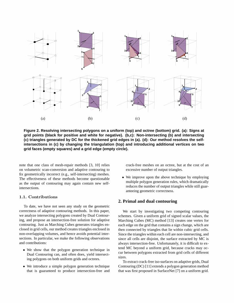
To create a crack-free and intersection-free iso-surface,we apply different polygon generation rules when contour-ing an octree grid. At each grid edgee exhibiting a signchange, we perform the two tests in Proposition 2 and pro-ceed by the following rules, as illustrated in Figure 5:
Rule 1: If both conditions in Proposition 2 hold, we outputthe trivial triangulationTe (Figure 5 (a)). Note thatwhene is shared by four cells, there are two possibletriangulations made by swapping the diagonal. Eithertriangulation that satisfies Proposition 2 is used.
Rule 2: If condition (1) holds but condition (2) fails, wegenerate a fan of triangles from the edge vertexve tocell verticesvc in all cellsc sharinge (Figure 5 (b)).
Te
ve
vc vc
vevf
Te
vc
ve
vc
ve vf
(a) (b) (c)
Figure 5. A top-down view of the three poly-gon generation rules for a grid edge sharedby four cells (top) and three cells (bottom).Cell vertices, face vertices and edge verticesare drawn as filled circles, empty squaresand empty circles.
Rule 3: If condition (1) fails, we generate a fan of trianglesfrom the edge vertexve to cell verticesvc in all cellsc
sharinge as well as face verticesvf on only those gridfacesf where condition (1) fails (Figure 5 (c)).
When the cell vertices, face vertices and edge verticesare placed interior to their corresponding cells, faces andedges, each polygon generation rule above results in trian-gles contained in a valid envelope, and hence the resultingtriangulated surface contains no intersecting polygons. Thesurface is also crack-free as the introduction of a face ver-tex on a grid face is consistent when processing every gridedge on that face. This polygon generation process can beefficiently implemented as recursive traversals on the octreeusing the procedures described in [11], which visits eachedge on the grid with running time linear to the size of theoctree.
Figure 2 (d) compares the result of intersection-free con-touring with that of DC on both uniform grid and octree.Note that self-intersections at the top and bottom of 2 (c)are resolved in the new contouring method respectively bypolygon generationRule 1 (i.e., by flipping the diagonal ofthe trivial triangulation) andRule 3.
4.3. Geometry creation
We follow the DC method [11] in computing the cell ver-tices. Specifically, given a signed uniform grid with Her-mite data attached to edges of the grid [10], the location of
each cell vertex is computed by minimizing a Quadratic En-ergy Function [6] defined by the Hermite data on the edgesof the cell. The minimization allows representation of sharpfeatures such as edges and corners. The uniform grid canbe adaptively simplified into an octree by merging cell ver-tices. Note that cell vertices can also be created from dis-tance maps as in SurfaceNet [7] or from scalar fields [16].
Given cell vertices on an octree, the remaining face ver-tices and edge vertices are placed to approximate the ge-ometry represented by the cell vertices while maintaining asmooth appearance.4 To locate an edge vertexve, we in-terpolate the locations of the cell vertices of cells sharinge. This is done by computing 2D barycentric coordinatesfor the cell vertices projected onto a plane orthogonal toe.Specifically, assume that the grid edgee has end points at{x, y, z−} and{x, y, z+}, and let each cell vertex aroundehave coordinate{xi, yi, zi}, thez component ofve is com-puted as:
z =∑
i
wizi
wherewi are affine weights satisfying∑
i wi = 1. To bet-ter approximate the underlying geometry, we further requirethat when{xi, yi, zi} forms a triangle or a planar quadrilat-eral,{x, y, z} should lie on the same plane. Thereforewi
must also satisfy thelinear precisionproperty:
x =∑
i
wixi, and y =∑
i
wiyi (1)
There are a wealth of techniques for computing weightsof this form on a 2D plane. We choose the Mean Valueweights [5] due to its stability and positivity even for non-convex shapes (which are common for the projected poly-gon{xi, yi}). To ensure thatve lies on the edgee, we fur-ther clampz to be within[z−, z+].
To locate a face vertexvf , we take the intersection of thesupporting plane of the grid facef with the line connectingthe two cell vertices on each side off . If the intersectionpoint lies outsidef , we place the face vertexvf at the cen-troid of the edge vertices of all grid edges onf (observefrom polygon generationRule 3 that an edge vertex is cre-ated for each grid edge shared by a facef containing a facevertex).
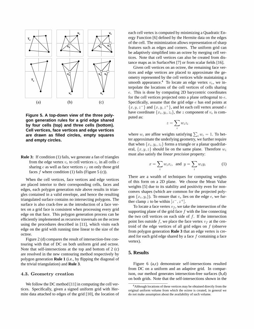
5. Results
Figure 6 (a,c) demonstrate self-intersections resultedfrom DC on a uniform and an adaptive grid. In compar-ison, our method generates intersection-free surfaces (b,d)on both grids. Note that the self-intersections shown in the
4Although locations of these vertices may be obtained directly from theoriginal uniform volume from which the octree is created, in general wedo not make assumption about the availability of such volume.

(a) (b) (c) (d)
Figure 6. Contouring a bunny on a uniform grid (a,b) and an oct ree grid (c,d). Dual Contouringcreates undesirable intersections in both cases (a,c), whe reas our method generates intersection-free surfaces (b,d).
(a) (b) (c)
Figure 7. Adaptive contouring of a simulated MEMS mirror mod el at octree depth 30 using DualContouring (a) and our method (b,c).
close-up views are resolved either by choosing an appropri-ate trivial triangulations (as in (b)) or by generating a trian-gle fan (as in (d)).
We next apply our method to extract iso-surfaces for oc-tree models of Micro Electro Mechanical (MEMS) devicesgenerated using the MEMulatorTM software [18]. Thesemodels (Figure 1 and 7) are generated by geometric model-ing a MEMS fabrication process using 2D layout masks asinput. A water-tight, intersection-free surface mesh needs tobe generated from the octree so that Finite Element Analysiscan be performed. The octree in each example has depth 30and is created from a scalar volume in a bottom-up fashion[16]. Observe from the figures that our new method pro-duces a geometrically correct mesh while preserving sur-face details.
Figure 8 compares our method with DC on large scannedmodels. The Dragon model was converted to Hermite dataat octree depth 10 using the PolyMender software [10], andthe surfaces shown are extracted after adaptive simplifica-
tion with increasing error thresholds. Although difficult tosee, Dual Contouring (top) generates 4583, 401, 74, and 30self-intersections respectively on each model. On the otherhand, the surfaces generated by our new method (bottom)contain no intersecting polygons.
Table 1 reports the performance of the algorithm on var-ious examples and compares it with DC. All tests are runon a P4 3.4GHz computer with 2GB memory. Our methodtypically takes 2 to 3 times longer than Dual Contouring,with the extra time spent on performing triangle-edge inter-section tests and computing locations of new vertices.
Note from Table 1 that when the octree is mostly “re-stricted” (i.e., the octree levels of two adjacent cells dif-fer at most by 1), such as examples in Figure 1, 7 and6 (a), our method results in little increase in total trian-gles because the two conditions in Proposition 2 are morelikely to hold. Since such restricted octrees are desirablein FEA-type applications to provide graded meshes withoutwildly varying element size, our method provides a low-

(a) (b) (c) (d)
Figure 8. Adaptive simplification of a complex model. DC (top ) results in 4583, 401, 74 and 30 self-intersections respectively on each surface. The surfaces g enerated by our method (bottom) areintersection-free.
overhead, intersection-free iso-surfacing solution for theseapplications. When applying our method to adaptively sim-plified scanned models, where the octree can be highly non-restricted, a larger increase in the polygon count is ob-served. Nevertheless, such increase is typically less than50% even in the most complex examples.
Time Triangles Intersections Time Triangles(DC) (DC) (DC) (IC) (IC)
Fig 1 0.015 6644 16 0.016 6918Fig 6 (b) 0.016 16194 58 0.047 22594Fig 6 (a) 0.062 91720 438 0.109 91728
Fig 7 0.047 80990 109 0.11 81850Fig 8 (d) <1ms 1712 30 <1ms 2353Fig 8 (c) 0.016 11128 74 0.031 15255Fig 8 (b) 0.063 72366 401 0.203 103724Fig 8 (a) 0.547 659948 4583 2.64 1025807
Table 1. Polygon generation time in secondsof Dual Contouring (DC) and our intersection-free contouring (IC) (timing excludes I/O andoctree simplification).
6. Discussion
In this paper we present a new method for extractingcrack-free and intersection-free surfaces on adaptive grids.Computing geometrically correct iso-surfaces is an impor-tant yet under-addressed area. As future work, we planto incorporate recent developments in adaptive contouring[19, 1, 20] to improve topological flexibility of the currentalgorithm, e.g., to allow multiple vertices in a cell, on aface or on an edge and to generate a topologically man-
ifold surface. Moreover, we shall also investigate tighterconditions than those in Theorem 1 to further reduce thetriangle overhead of the current method. For example, aninteresting question that we are still seeking an answer foris whether applying polygon generationRule 1 (i.e., alwaysusing a trivial triangulation) alone is sufficient to createanintersection-free surface on an uniform grid.
7. Acknowledgement
We would like to thank Zyvex Corporation for the per-mission to use the Mirror and Actuator Pads models, andthanks to the Stanford 3D Scanning Repository for theBunny and Dragon models.
References
[1] K. Ashida and N. I. Badler. Feature preserving manifoldmesh from an octree. InSymposium on Solid Modeling andApplications, pages 292–297, 2003.
[2] H. Baker. Building surfaces of evolution: The weaving wall.IJCV, 3:51–71, 1989.
[3] S. Bischoff, D. Pavic, and L. Kobbelt. Automatic restorationof polygon models.ACM Trans. Graph., 24(4):1332–1352,2005.
[4] J. Bloomenthal. Polygonization of implicit surfaces.Com-puter Aided Geometric Design, 5(4):341–356, 1988.
[5] M. S. Floater. Mean value coordinates.Computer AidedGeometric Design, 20(1):19–27, 2003.
[6] M. Garland and P. S. Heckbert. Surface simplification us-ing quadric error metrics. InProceedings of SIGGRAPH 97,Computer Graphics Proceedings, Annual Conference Series,pages 209–216, Los Angeles, California, August 1997. ACMSIGGRAPH / Addison Wesley.
[7] S. F. F. Gibson. Using distance maps for accurate surfacereconstruction in sampled volumes. In1998 Volume Visual-ization Symposium, pages 23–30. IEEE, October 1998.

[8] S. Gottschalk. Separating axis theorem.Technical ReportTR96-024, Dept. of Computer Science, UNC Chapel Hill,1996.
[9] A. Greß and R. Klein. Efficient representation and extractionof 2-manifold isosurfaces using kd-trees.Graphical Models,66(6):370–397, 2004.
[10] T. Ju. Robust repair of polygonal models.ACM Trans.Graph., 23(3):888–895, 2004.
[11] T. Ju, F. Losasso, S. Schaefer, and J. Warren. Dual con-touring of hermite data.ACM Transactions on Graphics,21(3):339–346, July 2002. ISSN 0730-0301 (Proceedingsof ACM SIGGRAPH 2002).
[12] L. P. Kobbelt, M. Botsch, U. Schwanecke, and H.-P. Seidel.Feature-sensitive surface extraction from volume data. InProceedings of SIGGRAPH 2001, Computer Graphics Pro-ceedings, Annual Conference Series, pages 57–66. ACMPress / ACM SIGGRAPH, August 2001.
[13] W. E. Lorensen and H. E. Cline. Marching cubes: A highresolution 3d surface construction algorithm. InComputerGraphics (Proceedings of SIGGRAPH 87), volume 21, pages163–169, Anaheim, California, July 1987.
[14] G. M. Nielson. Dual marching cubes. InVIS ’04: Proceed-ings of the conference on Visualization ’04, pages 489–496,Washington, DC, USA, 2004. IEEE Computer Society.
[15] G. M. Nielson and B. Hamann. The asymptotic decider: Re-solving the ambiguity in marching cubes. InIEEE Visualiza-tion, pages 83–93, 1991.
[16] E. Parker and T. Udeshi. Exploiting self-similarity in geom-etry for voxel based solid modeling. InSM ’03: Proceedingsof the eighth ACM symposium on Solid modeling and appli-cations, pages 157–166, New York, NY, USA, 2003. ACMPress.
[17] S. Schaefer and J. Warren. Dual marching cubes: Primal con-touring of dual grids. InPG ’04: Proceedings of the Com-puter Graphics and Applications, 12th Pacific Conference on(PG’04), pages 70–76, Washington, DC, USA, 2004. IEEEComputer Society.
[18] T. Udeshi and E. Parker. MEMulatorTM , a fast and accurategeometric modeling, visualization and mesh generation toolfor 3D MEMS design and simulation.Technical Proceedingsof the 2003 Nanotechnology Conference and Trade Show,pages 480–484, 2003.
[19] G. Varadhan, S. Krishnan, Y. Kim, and D. Manocha. Feature-sensitive subdivision and iso-surface reconstruction. InIEEEVisualization 2003, pages 99–106. IEEE, 2003.
[20] N. Zhang, W. Hong, and A. Kaufman. Dual contouring withtopology-preserving simplification using enhanced cell rep-resentation. InVIS ’04: Proceedings of the conference onVisualization ’04, pages 505–512, Washington, DC, USA,2004. IEEE Computer Society.
A. Proof of proposition 2Proof: Recall that an envelopeEe involves the grid edgee,the cell vertices in cells sharinge, and face vertices on facessharinge. When condition 1 holds, we can construct a validenvelope by placing the face vertexvf on each facef at theintersection betweenf and an edge ofTe connecting cellvertices in face-adjacent cells (see Figure 4 (b)). If condi-tion 1 fails at some edge ofTe, no placement of face verticeswill result in a valid envelope that contains that edge ofTe.
We next show that, when condition (1) holds andEe isconstructed as above,Te is completely contained inEe ifand only if condition (2) is satisfied. One point that wewill be relying on is thatEe now becomes the union of thetetrahedra each formed bye and one edge ofTe connectingcell vertices in face-adjacent cells.
If Te is a triangle, and assuming thatTe intersectse atve,we can splitTe into three triangles usingve, each of whichlies in the tetrahedra formed bye and an edge ofTe. There-fore Te lies in Ee, which is the union of these tetrahedra.To show necessity, we assumeTe is contained inEe. Sinceeach edge ofTe passes through a grid face that sharese,Te intersects with the supporting line ofe at some pointve.Note thatve must lie one, because the extension ofe is notcontained in the envelopeEe.
v1 v4
v2 v3
ve
p
v1 v4
v2 v3
ve
p
(a) (b)
Figure 9. Notations for proving Proposition 2.
If Te consists of two trianglest1, t2 that form a quadri-lateral, let the triangles have verticest1 = {v1, v2, v3} andt2 = {v1, v3, v4}. Without loss of generality, assume thatt1intersectse at ve and that diagonald = {v1, v3} intersectsthe trianglet′ formed bye andv4 at p, as shown in Fig-ure 9 (a). We can useve, p to split the two triangles into 6smaller triangles, as shown in Figure 9 (b). We observe that{v1, v2, ve} lies in the tetrahedron formed bye and{v1, v2},{v2, v3, ve} lies in the tetrahedron formed bye and{v2, v3},{v3, p, ve} and{v3, v4, p} lie in the tetrahedron formed byeand{v3, v4}, and{v1, ve, p} and{v1, p, v4} lie in the tetra-hedron formed bye and{v4, v1}. Therefore, the originaltrianglest1, t2 are contained in the envelopeEe, which isunion of the four tetrahedra. To show necessity, we assumethat t1, t2 are contained inEe. Following a similar argu-ment as above, eithert1 or t2 must intersect with the sup-porting line ofe at some pointve, and thatve must lie one. Assuming thatve lies ont1, the diagonald must inter-sect the supporting plane of the trianglet′ at some pointp,which lies in the cell containingv4. Note thatp must lie ont′, as the extension oft′ on its supporting plane within thecell containingv4 is not contained in the envelopeEe. �