Embed Size (px)
Citation preview
International Journal of Heat and Mass Transfer 68 (2014) 703–715
Contents lists available at ScienceDirect
International Journal of Heat and Mass Transfer
journal homepage: www.elsevier .com/locate / i jhmt
Flow boiling phenomena in a single annular flow regimein microchannels (I): Characterization of flow boiling heattransfer
0017-9310/$ - see front matter � 2013 Elsevier Ltd. All rights reserved.http://dx.doi.org/10.1016/j.ijheatmasstransfer.2013.09.058
⇑ Corresponding author.E-mail address: [email protected] (C. Li).
Fanghao Yang a, Xianming Dai a, Yoav Peles b, Ping Cheng c, Jamil Khan a, Chen Li a,⇑a Department of Mechanical Engineering, University of South Carolina, 300 Main St, Columbia, SC 29208, USAb Department of Mechanical, Aerospace & Nuclear Engineering, Rensselaer Polytechnic Institute, 110 8th St, Troy, NY 12180, USAc School of Mechanical and Power Engineering, Shanghai Jiaotong University, 800 Dong Chuan Rd, Shanghai 200240, China
a r t i c l e i n f o a b s t r a c t
Article history:Available online 17 October 2013
Keywords:Enhanced flow boilingMicrochannelSuperhydrophilic silicon nanowireSingle annular flow
Flow boiling with deionized water in silicon (Si) microchannels was drastically enhanced in a singleannular flow boiling regime enabled by superhydrophilic Si nanowire inner walls. Part I of this studyfocuses on characterizing enhanced flow boiling heat transfer. Part II focuses on revealing mechanismsin governing pressure drop and critical heat flux (CHF). Compared to flow boiling in plain-wall micro-channels without using inlet restrictors (IRs), the average heat transfer coefficient (HTC) and CHF wereenhanced by up to 326% and 317% at a mass flux of 389 kg/m2 s, respectively. Additionally, comparedwith flow boiling in microchannels with IRs, HTC of flow boiling in the single annular flow was enhancedby up to 248%; while CHF in the new flow boiling regime was 6.4–25.8% lower. The maximum HTCreached 125.4 kW/m2 K at a mass flux of 404 kg/m2 s near the exits of microchannels. The significantlypromoted nucleate boiling, induced liquid film renewal, and enhanced thin-film evaporation in theself-stabilized and single flow boiling regime are the primary reasons behind the significant heat transferenhancements during flow boiling.
� 2013 Elsevier Ltd. All rights reserved.
1. Introduction
Flow boiling in microchannels has been extensively studied inthe last decade [1–4] as it advantages for a range of applicationsincluding cooling high power microelectronics [1,5,6], compactheat exchangers, and chemical reactors [7–10]. Significant progresshas been made in understanding two-phase heat transfermechanisms [11,12], two-phase flow instabilities [13–15], andcritical heat flux (CHF) mechanisms [16–18]. Various techniquessuch as micro reentry cavities [19], microporous structures [12],nanostructures [20–22], inlet restrictors (IRs) [15,23], pin fins[24], microjets [25], and seed bubbles [26,27] were developed topromote flow boiling in microchannels. Specifically, micro cavitiesand micro/nanostructures can improve nucleate boiling byincreasing active nucleation site density. IRs can improve CHFconditions by effectively suppressing reverse flows and hence flowboiling instabilities. Microjets were used to promote convectionsby disturbing flows in microchannels. However, these reportedtechniques have various drawbacks, such as the dramaticallyincreased pressure drop resulting from IRs [15], reduced reliabilityinduced by complex structures [25–27], and low HTC on IRs and
finned boiling surfaces [4,15,23,24,28]. Most recently, thermallyinduced high frequency two-phase oscillations were inducedto generate mixing and hence significantly enhance flow boilingin microchannels [29,30]. However, none of these techniquesaimed to enhance flow boiling in microchannels throughmanipulating or even controlling two-phase flow structures, i.e.,regimes.
During flow boiling in microchannels, boiling surfaces play crit-ical roles in governing bubble nucleation, growth, separations,interactions, and two-phase flow regimes. Microchannels are usu-ally microfabricated on silicon substrates by wet-etching or deepreactive ion etching (DRIE) [6,8,31,32]. The peak-to-peak roughnessof etched silicon wafers can be as low as 3 nm at the bottom wall[33] and less than 300 nm at scalloped sidewalls [34], which arenot favored by nucleate boiling due to the lack of favorable nucle-ation cavities, consequently, result in explosive boiling and lowheat transfer rate because of high onset of nucleate boiling (ONB)[35]. Various artificial nucleation cavities were developed toenhance nucleate boiling [12,36,37]. Recently, one dimensional(1D) nanosturctures such as nanowires (NWs) [38,39] and carbonnanotubes (CNTs) [40–42] were used to enhance nucleate poolboiling and convective boiling in microchannels [20–22,40,43,44].Enhanced HTC and CHF were reported because of the higher nucle-ation site density and enhanced wettability. However, the role of
Nomenclature
A area, m2
Cp heat capacity at constant pressure, J/kg KD diameter, m_Db bubble growth velocity, m/sF force, NG mass flux, kg/m2 s�h average heat transfer coefficient, W/m2 Khfg latent heat of vaporization, kJ/kgH channel height, mI electrical current, Ak thermal conductivity, W/m KK slope of linear function, X/KL channel Length, mm parameter for pin efficiency_m mass flow rate, kg/s
N number of microchannelsp pressure, N/m2
P power, W_Q heat loss, W
q00 heat flux, W/cm2
R electrical resistance, Xt thickness, mT temperature, �CT average temperature, �CDT superheat, KDTsub subcooling temperature, Ku velocity, m/s�u average flow velocity, m/sV electrical voltage, V
W microchannel width, mWunit the width of a microchannel unit, m
Greek symbolsc surface tension, N/mh contact angleg fin efficiencyv vapor qualityq density, kg/m3
dt boundary layer thickness, m
Subscriptsb bubbleCHF critical heat fluxc cross-sectionald departuree exiteff effectiveHTC heat transfer coefficienti inletl liquids silicon layer between heater and microchannel basesat saturated1/ single-phase2/ two-phasev vaporw wall
θ
θ
(a)
(c)
(b)
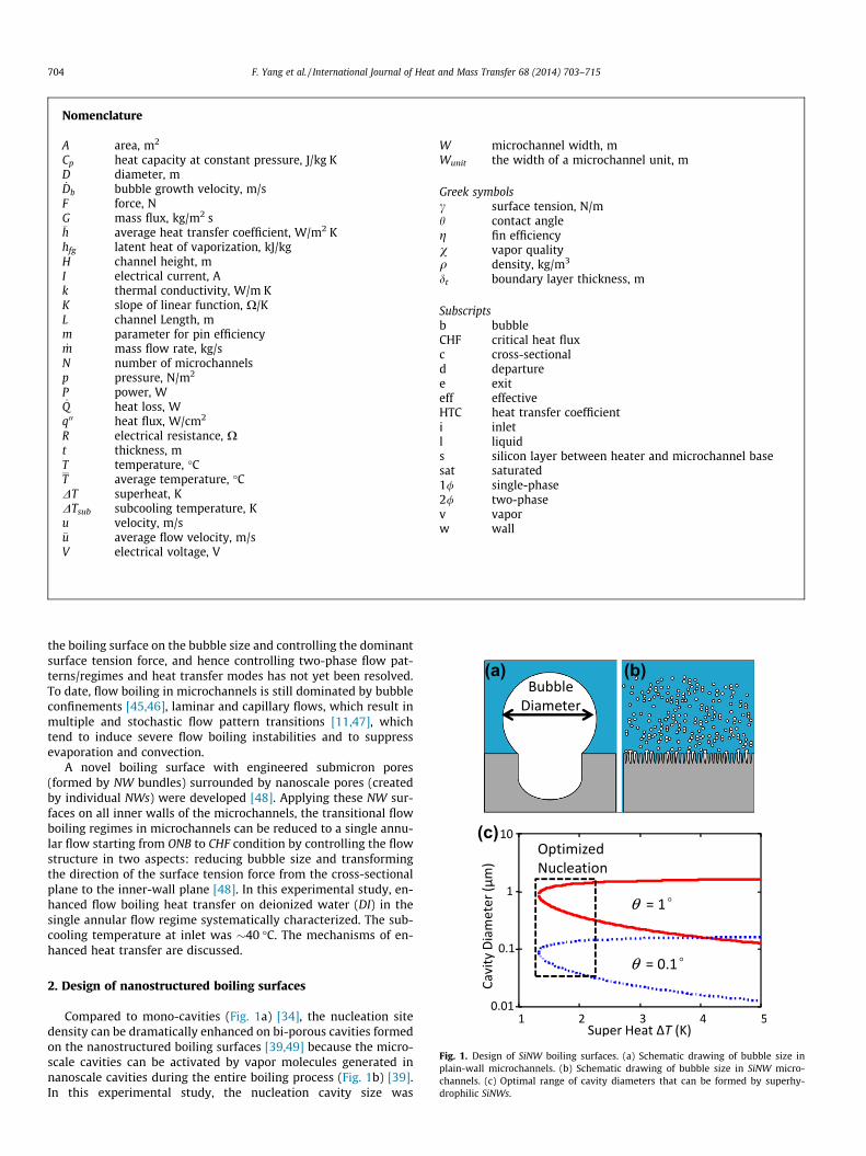
Fig. 1. Design of SiNW boiling surfaces. (a) Schematic drawing of bubble size inplain-wall microchannels. (b) Schematic drawing of bubble size in SiNW micro-channels. (c) Optimal range of cavity diameters that can be formed by superhy-drophilic SiNWs.
704 F. Yang et al. / International Journal of Heat and Mass Transfer 68 (2014) 703–715
the boiling surface on the bubble size and controlling the dominantsurface tension force, and hence controlling two-phase flow pat-terns/regimes and heat transfer modes has not yet been resolved.To date, flow boiling in microchannels is still dominated by bubbleconfinements [45,46], laminar and capillary flows, which result inmultiple and stochastic flow pattern transitions [11,47], whichtend to induce severe flow boiling instabilities and to suppressevaporation and convection.
A novel boiling surface with engineered submicron pores(formed by NW bundles) surrounded by nanoscale pores (createdby individual NWs) were developed [48]. Applying these NW sur-faces on all inner walls of the microchannels, the transitional flowboiling regimes in microchannels can be reduced to a single annu-lar flow starting from ONB to CHF condition by controlling the flowstructure in two aspects: reducing bubble size and transformingthe direction of the surface tension force from the cross-sectionalplane to the inner-wall plane [48]. In this experimental study, en-hanced flow boiling heat transfer on deionized water (DI) in thesingle annular flow regime systematically characterized. The sub-cooling temperature at inlet was �40 �C. The mechanisms of en-hanced heat transfer are discussed.
2. Design of nanostructured boiling surfaces
Compared to mono-cavities (Fig. 1a) [34], the nucleation sitedensity can be dramatically enhanced on bi-porous cavities formedon the nanostructured boiling surfaces [39,49] because the micro-scale cavities can be activated by vapor molecules generated innanoscale cavities during the entire boiling process (Fig. 1b) [39].In this experimental study, the nucleation cavity size was
F. Yang et al. / International Journal of Heat and Mass Transfer 68 (2014) 703–715 705
optimized to enhance HTC by reducing the superheat, DT, i.e., thetemperature difference between wall and saturation temperature.As shown in Fig. 1c, the range of active cavity opening diameter, Dc,was estimated from Eq. (1) [50].
Dc max;min ¼dt sin h
2ð1þ cos hÞ �DT
DT þ DTsub
� �
� 1�ffiffiffiffiffiffiffiffiffiffiffiffiffiffiffiffiffiffiffiffiffiffiffiffiffiffiffiffiffiffiffiffiffiffiffiffiffiffiffiffiffiffiffiffiffiffiffiffiffiffiffiffiffiffiffiffiffiffiffiffiffiffiffiffiffiffiffiffiffiffiffiffiffiffi1� 8rf ðDT þ DTsubÞTsatð1þ cos hÞ
qvhfgdtDT2
s" #ð1Þ
where hfg, DTsub, h, rf, qv, and dt denote latent heat of vaporization,subcooling temperature, contact angle, surface tension, vapor den-sity, and thermal boundary layer thickness, respectively. With Eq.(1), the optimal range of nucleation cavity size on superhydrophilicsurfaces for water was estimated to be between 100 and 2000 nmwhen assuming the apparent contact angles between 0.1� and 1�.
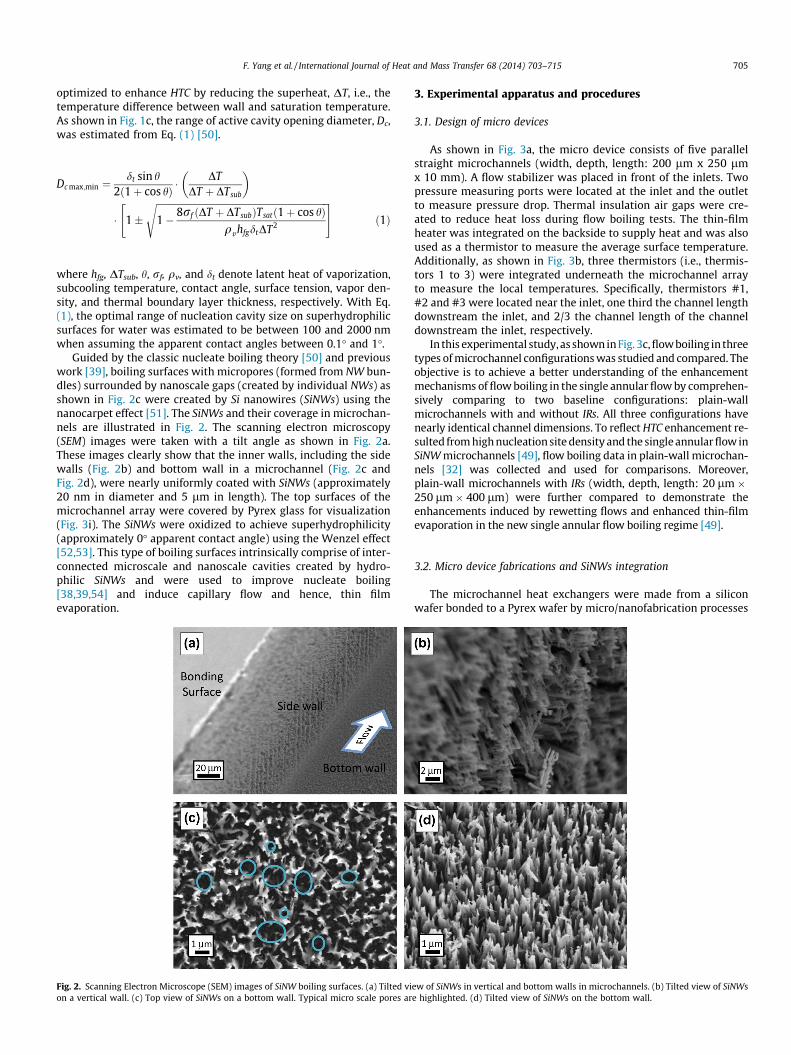
Guided by the classic nucleate boiling theory [50] and previouswork [39], boiling surfaces with micropores (formed from NW bun-dles) surrounded by nanoscale gaps (created by individual NWs) asshown in Fig. 2c were created by Si nanowires (SiNWs) using thenanocarpet effect [51]. The SiNWs and their coverage in microchan-nels are illustrated in Fig. 2. The scanning electron microscopy(SEM) images were taken with a tilt angle as shown in Fig. 2a.These images clearly show that the inner walls, including the sidewalls (Fig. 2b) and bottom wall in a microchannel (Fig. 2c andFig. 2d), were nearly uniformly coated with SiNWs (approximately20 nm in diameter and 5 lm in length). The top surfaces of themicrochannel array were covered by Pyrex glass for visualization(Fig. 3i). The SiNWs were oxidized to achieve superhydrophilicity(approximately 0� apparent contact angle) using the Wenzel effect[52,53]. This type of boiling surfaces intrinsically comprise of inter-connected microscale and nanoscale cavities created by hydro-philic SiNWs and were used to improve nucleate boiling[38,39,54] and induce capillary flow and hence, thin filmevaporation.
Fig. 2. Scanning Electron Microscope (SEM) images of SiNW boiling surfaces. (a) Tilted vion a vertical wall. (c) Top view of SiNWs on a bottom wall. Typical micro scale pores ar
3. Experimental apparatus and procedures
3.1. Design of micro devices
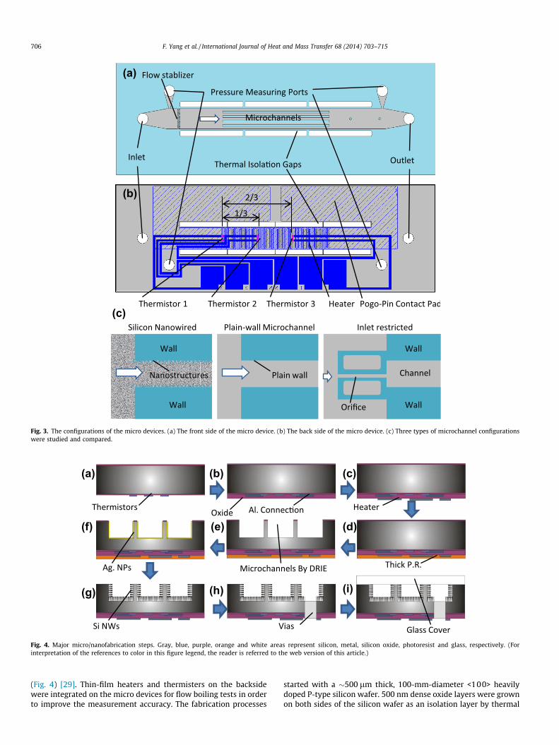
As shown in Fig. 3a, the micro device consists of five parallelstraight microchannels (width, depth, length: 200 lm x 250 lmx 10 mm). A flow stabilizer was placed in front of the inlets. Twopressure measuring ports were located at the inlet and the outletto measure pressure drop. Thermal insulation air gaps were cre-ated to reduce heat loss during flow boiling tests. The thin-filmheater was integrated on the backside to supply heat and was alsoused as a thermistor to measure the average surface temperature.Additionally, as shown in Fig. 3b, three thermistors (i.e., thermis-tors 1 to 3) were integrated underneath the microchannel arrayto measure the local temperatures. Specifically, thermistors #1,#2 and #3 were located near the inlet, one third the channel lengthdownstream the inlet, and 2/3 the channel length of the channeldownstream the inlet, respectively.
In this experimental study, as shown in Fig. 3c, flow boiling in threetypes of microchannel configurations was studied and compared. Theobjective is to achieve a better understanding of the enhancementmechanisms of flow boiling in the single annular flow by comprehen-sively comparing to two baseline configurations: plain-wallmicrochannels with and without IRs. All three configurations havenearly identical channel dimensions. To reflect HTC enhancement re-sulted from high nucleation site density and the single annular flow inSiNW microchannels [49], flow boiling data in plain-wall microchan-nels [32] was collected and used for comparisons. Moreover,plain-wall microchannels with IRs (width, depth, length: 20 lm �250 lm� 400 lm) were further compared to demonstrate theenhancements induced by rewetting flows and enhanced thin-filmevaporation in the new single annular flow boiling regime [49].
3.2. Micro device fabrications and SiNWs integration
The microchannel heat exchangers were made from a siliconwafer bonded to a Pyrex wafer by micro/nanofabrication processes
ew of SiNWs in vertical and bottom walls in microchannels. (b) Tilted view of SiNWse highlighted. (d) Tilted view of SiNWs on the bottom wall.
(a)
(b)
(c)
Fig. 3. The configurations of the micro devices. (a) The front side of the micro device. (b) The back side of the micro device. (c) Three types of microchannel configurationswere studied and compared.
(a) (b)
(f) (e)
(c)
(d)
(g) (h) (i)
Fig. 4. Major micro/nanofabrication steps. Gray, blue, purple, orange and white areas represent silicon, metal, silicon oxide, photoresist and glass, respectively. (Forinterpretation of the references to color in this figure legend, the reader is referred to the web version of this article.)
706 F. Yang et al. / International Journal of Heat and Mass Transfer 68 (2014) 703–715
(Fig. 4) [29]. Thin-film heaters and thermisters on the backsidewere integrated on the micro devices for flow boiling tests in orderto improve the measurement accuracy. The fabrication processes
started with a �500 lm thick, 100-mm-diameter <100> heavilydoped P-type silicon wafer. 500 nm dense oxide layers were grownon both sides of the silicon wafer as an isolation layer by thermal
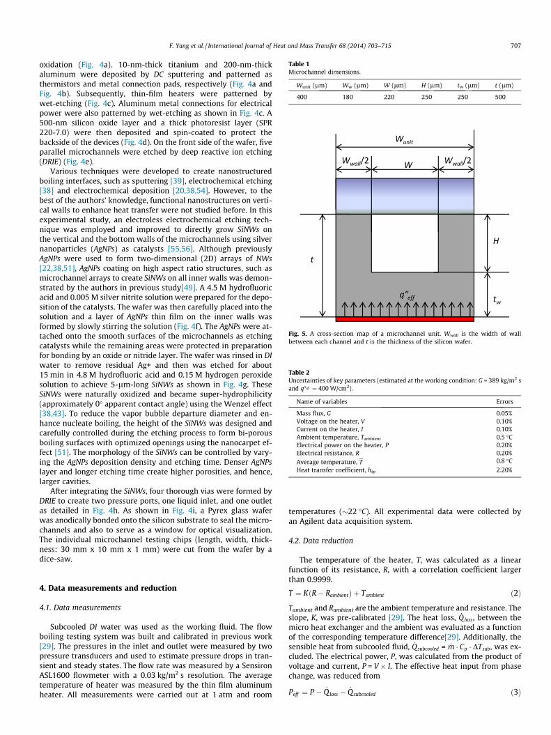
Table 1Microchannel dimensions.
Wunit (lm) Ww (lm) W (lm) H (lm) tw (lm) t (lm)
400 180 220 250 250 500
Fig. 5. A cross-section map of a microchannel unit. Wwall is the width of wallbetween each channel and t is the thickness of the silicon wafer.
Table 2Uncertainties of key parameters (estimated at the working condition: G = 389 kg/m2 sand q00eff ¼ 400 W/cm2).
Name of variables Errors
Mass flux, G 0.05%Voltage on the heater, V 0.10%Current on the heater, I 0.10%Ambient temperature, Tambient 0.5 �CElectrical power on the heater, P 0.20%Electrical resistance, R 0.20%Average temperature, T 0.8 �CHeat transfer coefficient, htp 2.20%
F. Yang et al. / International Journal of Heat and Mass Transfer 68 (2014) 703–715 707
oxidation (Fig. 4a). 10-nm-thick titanium and 200-nm-thickaluminum were deposited by DC sputtering and patterned asthermistors and metal connection pads, respectively (Fig. 4a andFig. 4b). Subsequently, thin-film heaters were patterned bywet-etching (Fig. 4c). Aluminum metal connections for electricalpower were also patterned by wet-etching as shown in Fig. 4c. A500-nm silicon oxide layer and a thick photoresist layer (SPR220-7.0) were then deposited and spin-coated to protect thebackside of the devices (Fig. 4d). On the front side of the wafer, fiveparallel microchannels were etched by deep reactive ion etching(DRIE) (Fig. 4e).
Various techniques were developed to create nanostructuredboiling interfaces, such as sputtering [39], electrochemical etching[38] and electrochemical deposition [20,38,54]. However, to thebest of the authors’ knowledge, functional nanostructures on verti-cal walls to enhance heat transfer were not studied before. In thisexperimental study, an electroless electrochemical etching tech-nique was employed and improved to directly grow SiNWs onthe vertical and the bottom walls of the microchannels using silvernanoparticles (AgNPs) as catalysts [55,56]. Although previouslyAgNPs were used to form two-dimensional (2D) arrays of NWs[22,38,51], AgNPs coating on high aspect ratio structures, such asmicrochannel arrays to create SiNWs on all inner walls was demon-strated by the authors in previous study[49]. A 4.5 M hydrofluoricacid and 0.005 M silver nitrite solution were prepared for the depo-sition of the catalysts. The wafer was then carefully placed into thesolution and a layer of AgNPs thin film on the inner walls wasformed by slowly stirring the solution (Fig. 4f). The AgNPs were at-tached onto the smooth surfaces of the microchannels as etchingcatalysts while the remaining areas were protected in preparationfor bonding by an oxide or nitride layer. The wafer was rinsed in DIwater to remove residual Ag+ and then was etched for about15 min in 4.8 M hydrofluoric acid and 0.15 M hydrogen peroxidesolution to achieve 5-lm-long SiNWs as shown in Fig. 4g. TheseSiNWs were naturally oxidized and became super-hydrophilicity(approximately 0� apparent contact angle) using the Wenzel effect[38,43]. To reduce the vapor bubble departure diameter and en-hance nucleate boiling, the height of the SiNWs was designed andcarefully controlled during the etching process to form bi-porousboiling surfaces with optimized openings using the nanocarpet ef-fect [51]. The morphology of the SiNWs can be controlled by vary-ing the AgNPs deposition density and etching time. Denser AgNPslayer and longer etching time create higher porosities, and hence,larger cavities.
After integrating the SiNWs, four thorough vias were formed byDRIE to create two pressure ports, one liquid inlet, and one outletas detailed in Fig. 4h. As shown in Fig. 4i, a Pyrex glass waferwas anodically bonded onto the silicon substrate to seal the micro-channels and also to serve as a window for optical visualization.The individual microchannel testing chips (length, width, thick-ness: 30 mm x 10 mm x 1 mm) were cut from the wafer by adice-saw.
4. Data measurements and reduction
4.1. Data measurements
Subcooled DI water was used as the working fluid. The flowboiling testing system was built and calibrated in previous work[29]. The pressures in the inlet and outlet were measured by twopressure transducers and used to estimate pressure drops in tran-sient and steady states. The flow rate was measured by a SensironASL1600 flowmeter with a 0.03 kg/m2 s resolution. The averagetemperature of heater was measured by the thin film aluminumheater. All measurements were carried out at 1 atm and room
temperatures (�22 �C). All experimental data were collected byan Agilent data acquisition system.
4.2. Data reduction
The temperature of the heater, T, was calculated as a linearfunction of its resistance, R, with a correlation coefficient largerthan 0.9999.
T ¼ KðR� RambientÞ þ Tambient ð2Þ
Tambient and Rambient are the ambient temperature and resistance. Theslope, K, was pre-calibrated [29]. The heat loss, _Qloss, between themicro heat exchanger and the ambient was evaluated as a functionof the corresponding temperature difference[29]. Additionally, thesensible heat from subcooled fluid, _Qsubcooled = _m � Cp � DTsub, was ex-cluded. The electrical power, P, was calculated from the product ofvoltage and current, P = V � I. The effective heat input from phasechange, was reduced from
Peff ¼ P � _Q loss � _Q subcooled ð3Þ
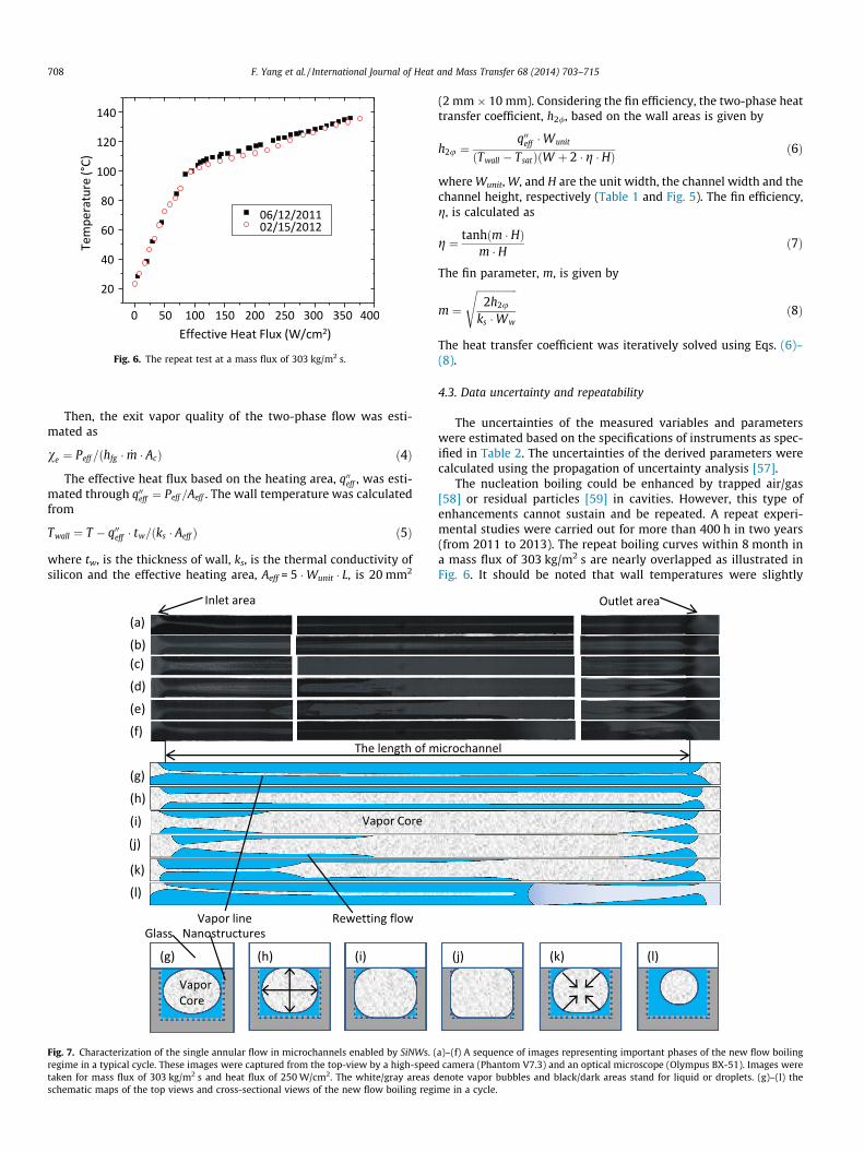
Fig. 6. The repeat test at a mass flux of 303 kg/m2 s.
708 F. Yang et al. / International Journal of Heat and Mass Transfer 68 (2014) 703–715
Then, the exit vapor quality of the two-phase flow was esti-mated as
ve ¼ Peff =ðhfg � _m � AcÞ ð4Þ
The effective heat flux based on the heating area, q00eff , was esti-mated through q00eff ¼ Peff =Aeff . The wall temperature was calculatedfrom
Twall ¼ T � q00eff � tw=ðks � Aeff Þ ð5Þ
where tw, is the thickness of wall, ks, is the thermal conductivity ofsilicon and the effective heating area, Aeff = 5 �Wunit � L, is 20 mm2
Fig. 7. Characterization of the single annular flow in microchannels enabled by SiNWs. (regime in a typical cycle. These images were captured from the top-view by a high-speedtaken for mass flux of 303 kg/m2 s and heat flux of 250 W/cm2. The white/gray areas dschematic maps of the top views and cross-sectional views of the new flow boiling regi
(2 mm � 10 mm). Considering the fin efficiency, the two-phase heattransfer coefficient, h2/, based on the wall areas is given by
h2u ¼q00eff �Wunit
ðTwall � TsatÞðW þ 2 � g � HÞ ð6Þ
where Wunit, W, and H are the unit width, the channel width and thechannel height, respectively (Table 1 and Fig. 5). The fin efficiency,g, is calculated as
g ¼ tanhðm � HÞm � H ð7Þ
The fin parameter, m, is given by
m ¼
ffiffiffiffiffiffiffiffiffiffiffiffiffiffiffiffi2h2u
ks �Ww
sð8Þ
The heat transfer coefficient was iteratively solved using Eqs. (6)–(8).
4.3. Data uncertainty and repeatability
The uncertainties of the measured variables and parameterswere estimated based on the specifications of instruments as spec-ified in Table 2. The uncertainties of the derived parameters werecalculated using the propagation of uncertainty analysis [57].
The nucleation boiling could be enhanced by trapped air/gas[58] or residual particles [59] in cavities. However, this type ofenhancements cannot sustain and be repeated. A repeat experi-mental studies were carried out for more than 400 h in two years(from 2011 to 2013). The repeat boiling curves within 8 month ina mass flux of 303 kg/m2 s are nearly overlapped as illustrated inFig. 6. It should be noted that wall temperatures were slightly
a)–(f) A sequence of images representing important phases of the new flow boilingcamera (Phantom V7.3) and an optical microscope (Olympus BX-51). Images were
enote vapor bubbles and black/dark areas stand for liquid or droplets. (g)–(l) theme in a cycle.
(a) (b)
(c) (d)
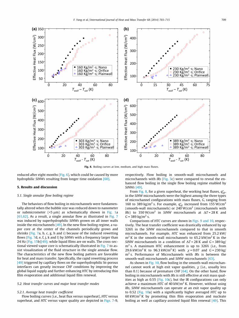
Fig. 8. Boiling curves at low, medium, and high mass fluxes.
F. Yang et al. / International Journal of Heat and Mass Transfer 68 (2014) 703–715 709
reduced after eight months (Fig. 6), which could be caused by morehydrophilic SiNWs resulting from longer time oxidation [60].
5. Results and discussion
5.1. Single annular flow boiling regime
The behaviors of flow boiling in microchannels were fundamen-tally altered when the bubble size was reduced down to nanometeror submicrometer (<5 lm) as schematically shown in Fig. 1a[61,62]. As a result, a single annular flow as illustrated in Fig. 7was induced by superhydrophilic SiNWs grown on all inner wallsinside the microchannels [49]. In the new flow boiling regime, a va-por core at the center of the channels periodically grows andshrinks (Fig. 7a, b, c, g, h and i) because of the induced rewettingflows (Fig. 7d, e, f, j, k and l) by SiNWs with a frequency larger than24 Hz (Fig. 15b)[49]; while liquid films are on walls. The cross-sec-tional viewed vapor core is schematically illustrated in Fig. 7 to as-sist visualization of the fluid structure in the single annular flow.The characteristics of the new flow boiling pattern are favorablefor heat and mass transfer. Specifically, the rapid rewetting process[49] triggered by capillary flows on the superhydrophilic bi-porousinterfaces can greatly increase CHF conditions by improving theglobal liquid supply and further enhancing HTC by introducing thinfilm evaporation and additional liquid film renewal.
5.2. Heat transfer curves and major heat transfer modes
5.2.1. Average heat transfer coefficientFlow boiling curves (i.e., heat flux versus superheat), HTC versus
superheat, and HTC versus vapor quality are depicted in Figs. 7-9,
respectively. Flow boiling in smooth-wall microchannels andmicrochannels with IRs (Fig. 3c) were compared to reveal the en-hanced flow boiling in the single flow boiling regime enabled bySiNWs [49].
From Fig. 8, for a given superheat, the working heat fluxes, q00eff ,in the SiNW microchannels were the highest among the three typesof microchannel configurations with mass fluxes, G, ranging from160 to 389 kg/m2 s. For example, q00eff increased from 155 W/cm2
(smooth-wall microchannels) or 240 W/cm2 (microchannels withIRs) to 350 W/cm2 in SiNW microchannels at DT = 28 K andG = 389 kg/m2 s.
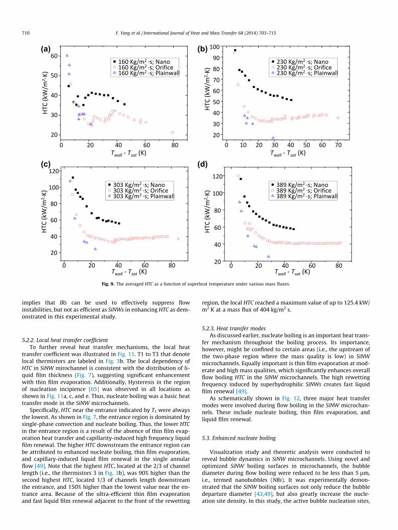
Comparisons of HTC curves are shown in Figs. 9 and 10, respec-tively. The heat transfer coefficient was drastically enhanced by up326% in the SiNW microchannels compared to that in smoothmicrochannels. For example, HTC was enhanced from 25.2 kW/m2 K in the smooth-wall microchannels to 65.2 kW/m2 K in theSiNW microchannels in a condition of DT = 28 K and G = 389 kg/m2 s. A maximum HTC enhancement is up to 326% (i.e., from29.6 kW/m2 K to 96.3 kW/m2 K) with v = 0.07 and G = 230 kg/m2 s. Performance of Microchannels with IRs is between thesmooth-wall microchannels and SiNW microchannels [63].
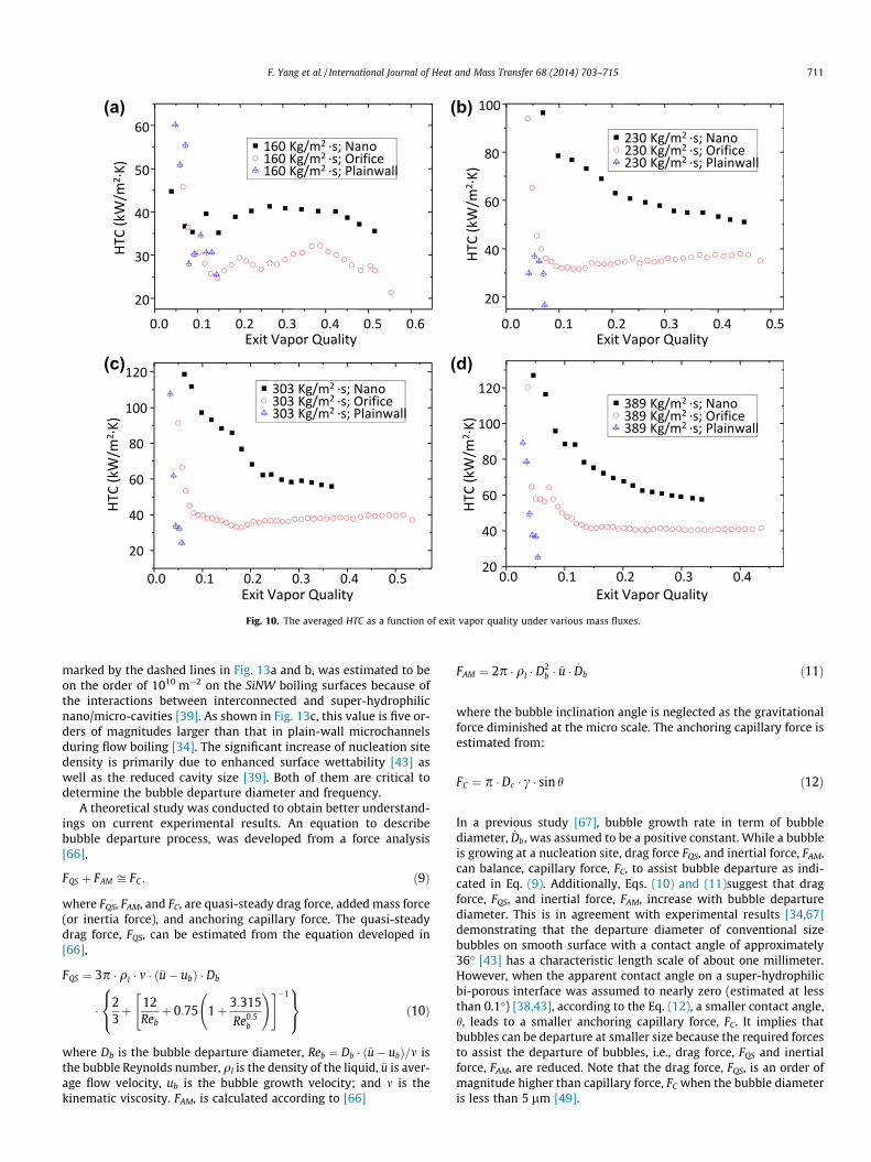
As shown in Fig. 10, flow boiling in the smooth-wall microchan-nel cannot work at high exit vapor qualities, v (i.e., usually lessthan 0.1) because of premature CHF [64]. On the other hand, flowboiling in microchannels with IRs is still effective at exit mass qual-ities as high as 0.55 (Fig. 10c), but the IR configurations can onlyachieve a maximum HTC of 40 kW/m2 K. However, without usingIRs, SiNW microchannels can operate at an exit vapor quality upto 0.52 (Fig. 10a) with a significantly higher averaged HTC up to60 kW/m2 K by promoting thin film evaporation and nucleateboiling as well as capillary-assisted liquid film renewal [49]. This
(a) (b)
(c) (d)
Fig. 9. The averaged HTC as a function of superheat temperature under various mass fluxes.
710 F. Yang et al. / International Journal of Heat and Mass Transfer 68 (2014) 703–715
implies that IRs can be used to effectively suppress flowinstabilities, but not as efficient as SiNWs in enhancing HTC as dem-onstrated in this experimental study.
5.2.2. Local heat transfer coefficientTo further reveal heat transfer mechanisms, the local heat
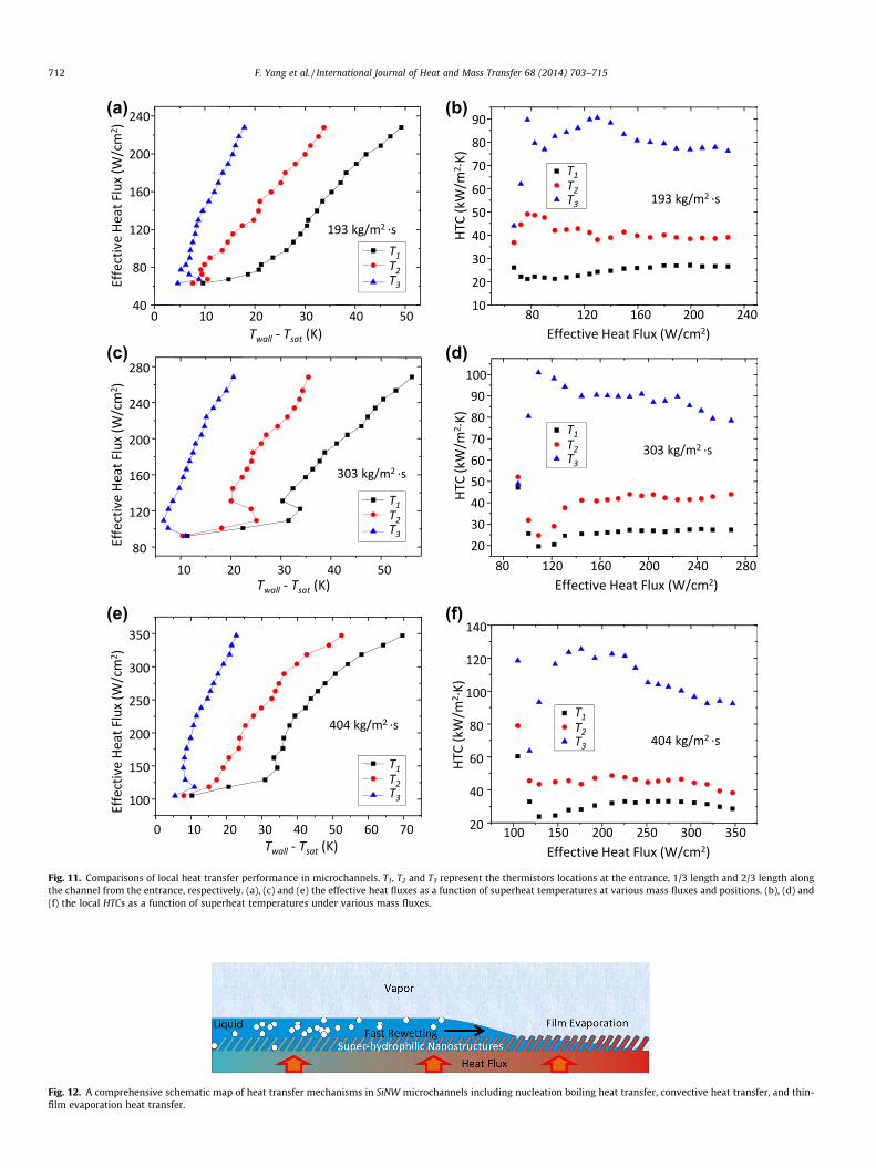
transfer coefficient was illustrated in Fig. 11. T1 to T3 that denotelocal thermistors are labeled in Fig. 3b. The local dependency ofHTC in SiNW mirochannel is consistent with the distribution of li-quid film thickness (Fig. 7), suggesting significant enhancementwith thin film evaporation. Additionally, Hysteresis in the regionof nucleation incipience [65] was observed in all locations asshown in Fig. 11a, c, and e. Thus, nucleate boiling was a basic heattransfer mode in the SiNW microchannels.
Specifically, HTC near the entrance indicated by T1 were alwaysthe lowest. As shown in Fig. 7, the entrance region is dominated bysingle-phase convection and nucleate boiling. Thus, the lower HTCin the entrance region is a result of the absence of thin film evap-oration heat transfer and capillarity-induced high frequency liquidfilm renewal. The higher HTC downstream the entrance region canbe attributed to enhanced nucleate boiling, thin film evaporation,and capillary-induced liquid film renewal in the single annularflow [49]. Note that the highest HTC, located at the 2/3 of channellength (i.e., the thermistors 3 in Fig. 3b), was 90% higher than thesecond highest HTC, located 1/3 of channels length downstreamthe entrance, and 150% higher than the lowest value near the en-trance area. Because of the ultra-efficient thin film evaporationand fast liquid film renewal adjacent to the front of the rewetting
region, the local HTC reached a maximum value of up to 125.4 kW/m2 K at a mass flux of 404 kg/m2 s.
5.2.3. Heat transfer modesAs discussed earlier, nucleate boiling is an important heat trans-
fer mechanism throughout the boiling process. Its importance,however, might be confined to certain areas (i.e., the upstream ofthe two-phase region where the mass quality is low) in SiNWmicrochannels. Equally important is thin film evaporation at mod-erate and high mass qualities, which significantly enhances overallflow boiling HTC in the SiNW microchannels. The high rewettingfrequency induced by superhydrophilic SiNWs creates fast liquidfilm renewal [49].
As schematically shown in Fig. 12, three major heat transfermodes were involved during flow boiling in the SiNW microchan-nels. These include nucleate boiling, thin film evaporation, andliquid film renewal.
5.3. Enhanced nucleate boiling
Visualization study and theoretic analysis were conducted toreveal bubble dynamics in SiNW microchannels. Using novel andoptimized SiNW boiling surfaces in microchannels, the bubblediameter during flow boiling were reduced to be less than 5 lm,i.e., termed nanobubbles (NBs). It was experimentally demon-strated that the SiNW boiling surfaces not only reduce the bubbledeparture diameter [43,49], but also greatly increase the nucle-ation site density. In this study, the active bubble nucleation sites,
(a) (b)
(c) (d)
Fig. 10. The averaged HTC as a function of exit vapor quality under various mass fluxes.
F. Yang et al. / International Journal of Heat and Mass Transfer 68 (2014) 703–715 711
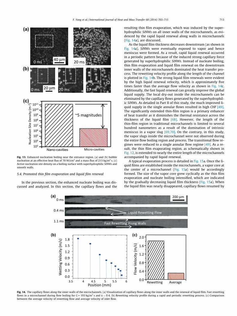
marked by the dashed lines in Fig. 13a and b, was estimated to beon the order of 1010 m�2 on the SiNW boiling surfaces because ofthe interactions between interconnected and super-hydrophilicnano/micro-cavities [39]. As shown in Fig. 13c, this value is five or-ders of magnitudes larger than that in plain-wall microchannelsduring flow boiling [34]. The significant increase of nucleation sitedensity is primarily due to enhanced surface wettability [43] aswell as the reduced cavity size [39]. Both of them are critical todetermine the bubble departure diameter and frequency.
A theoretical study was conducted to obtain better understand-ings on current experimental results. An equation to describebubble departure process, was developed from a force analysis[66],
FQS þ FAM ffi FC ; ð9Þ
where FQS, FAM, and FC, are quasi-steady drag force, added mass force(or inertia force), and anchoring capillary force. The quasi-steadydrag force, FQS, can be estimated from the equation developed in[66],
FQS ¼ 3p � ql � m � ð�u� ubÞ � Db
� 23þ 12
Rebþ 0:75 1þ 3:315
Re0:5b
!" #�18<:
9=; ð10Þ
where Db is the bubble departure diameter, Reb ¼ Db � ð�u� ubÞ=m isthe bubble Reynolds number, ql is the density of the liquid, �u is aver-age flow velocity, ub is the bubble growth velocity; and m is thekinematic viscosity. FAM, is calculated according to [66]
FAM ¼ 2p � ql � D2b � �u � _Db ð11Þ
where the bubble inclination angle is neglected as the gravitationalforce diminished at the micro scale. The anchoring capillary force isestimated from:
FC ¼ p � Dc � c � sin h ð12Þ
In a previous study [67], bubble growth rate in term of bubblediameter, _Db, was assumed to be a positive constant. While a bubbleis growing at a nucleation site, drag force FQS, and inertial force, FAM,can balance, capillary force, FC, to assist bubble departure as indi-cated in Eq. (9). Additionally, Eqs. (10) and (11)suggest that dragforce, FQS, and inertial force, FAM, increase with bubble departurediameter. This is in agreement with experimental results [34,67]demonstrating that the departure diameter of conventional sizebubbles on smooth surface with a contact angle of approximately36� [43] has a characteristic length scale of about one millimeter.However, when the apparent contact angle on a super-hydrophilicbi-porous interface was assumed to nearly zero (estimated at lessthan 0.1�) [38,43], according to the Eq. (12), a smaller contact angle,h, leads to a smaller anchoring capillary force, FC. It implies thatbubbles can be departure at smaller size because the required forcesto assist the departure of bubbles, i.e., drag force, FQS and inertialforce, FAM, are reduced. Note that the drag force, FQS, is an order ofmagnitude higher than capillary force, FC when the bubble diameteris less than 5 lm [49].
(a) (b)
(c) (d)
(e) (f)
Fig. 11. Comparisons of local heat transfer performance in microchannels. T1, T2 and T3 represent the thermistors locations at the entrance, 1/3 length and 2/3 length alongthe channel from the entrance, respectively. (a), (c) and (e) the effective heat fluxes as a function of superheat temperatures at various mass fluxes and positions. (b), (d) and(f) the local HTCs as a function of superheat temperatures under various mass fluxes.
Fig. 12. A comprehensive schematic map of heat transfer mechanisms in SiNW microchannels including nucleation boiling heat transfer, convective heat transfer, and thin-film evaporation heat transfer.
712 F. Yang et al. / International Journal of Heat and Mass Transfer 68 (2014) 703–715
μ
μ
Nano-cavities
(a)
(b)
(c)
Fig. 13. Enhanced nucleation boiling near the entrance region. (a) and (b) bubblenucleation at an effective heat flux of 70 W/cm2 and a mass flux of 213 kg/m2 s. (c)Active nucleation site density on a boiling surface with superhydrophilic SiNWs andsmooth walls.
F. Yang et al. / International Journal of Heat and Mass Transfer 68 (2014) 703–715 713
5.4. Promoted thin film evaporation and liquid film renewal
In the previous section, the enhanced nucleate boiling was dis-cussed and analyzed. In this section, the capillary flows and the
(a)
(b)
Fig. 14. The capillary flows along the inner walls of the microchannels. (a) Visualization oflows in a microchannel during flow boiling for G = 193 kg/m2 s and �u ¼ 0:4. (b) Rewetbetween the average velocity of rewetting flow and average velocity of inlet flow.
resulting thin film evaporation, which was induced by the super-hydrophilic SiNWs on all inner walls of the microchannels, as evi-denced by the rapid liquid renewal along walls in microchannels(Fig. 14a), are discussed.
As the liquid film thickness decreases downstream (as shown inFig. 14a), SiNWs were eventually exposed to vapor and hencemeniscus were formed. As a result, rapid liquid renewal occurredin a periodic pattern because of the induced strong capillary forcegenerated by superhydrophilic SiNWs. Instead of nucleate boiling,thin film evaporation and liquid film renewal on the downstreaminner walls of the microchannels dominated the heat transfer pro-cess. The rewetting velocity profile along the length of the channelis plotted in Fig. 14b. The strong liquid film renewals were evidentby the high liquid renewal velocity, which is approximately fivetimes faster than the average flow velocity as shown in Fig. 14c.Additionally, the fast liquid renewal can greatly improve the globalliquid supply. The local dry-out inside the microchannels can beeliminated by the capillary flows generated by the superhydrophil-ic SiNWs. As detailed in Part II of this study, the much improved li-quid supply in the single annular flows resulted in high CHF [49].The significantly extended thin-film region is a primary enhancerof heat transfer as it diminishes the thermal resistance across thethickness of the liquid film [68]. However, the length of thethin-film region in traditional microchannels is limited to severalhundred nanometers as a result of the domination of intrinsicmeniscus in a vapor slug [69,70]. On the contrary, in this study,the vapor slugs inside the microchannel were not observed duringthe entire flow boiling region and process. The transitional flow re-gimes were reduced to a single annular flow regime [49]. As a re-sult, the thin film evaporating region, as schematically shown inFig. 12, is extended to nearly the entire length of the microchannelsaccompanied by rapid liquid renewal.
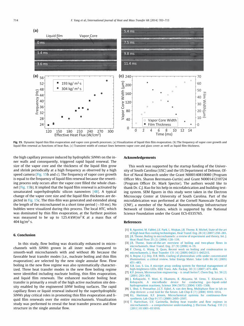
A typical evaporation process is detailed in Fig. 15a. Once the li-quid films are established inside the microchannels, a vapor core atthe center of a microchannel (Fig. 15a) would be accordinglyformed. The size of the vapor core grew cyclically as the thin filmevaporation and nucleate boiling intensified, which are indicatedby the gradually decreasing liquid film thickness (Fig. 15a). Whenthe liquid film was nearly disappeared, capillary flows resumed by
μ
(c)
f capillary flows along the inner walls and the renewal of liquid film. Fast rewettingting velocity profile during a rapid and periodic rewetting process. (c) Comparison
(a)
(a) (c)
Fig. 15. Dynamic liquid thin film evaporation and vapor core growth processes. (a) Visualization of liquid thin film evaporation. (b) The frequency of vapor core growth andliquid film renewal as functions of heat flux. (c) Transient width of contact lines between vapor core and glass cover as well as liquid film thickness.
714 F. Yang et al. / International Journal of Heat and Mass Transfer 68 (2014) 703–715
the high capillary pressure induced by hydrophilic SiNWs on the in-ner walls and consequently, triggered rapid liquid renewal. Thesize of the vapor core and the thickness of the liquid film growand shrink periodically at a high frequency as observed by a highspeed camera (Fig. 15b and c). The frequency of vapor core growthis equal to the frequency of liquid film renewal because the rewett-ing process only occurs after the vapor core filled the whole chan-nel (Fig. 15b). It implied that the liquid film renewal is activated byunsaturated superhydrophilic silicon nanowires [48]. A typicalchange of the vapor core size and the liquid film thickness are de-picted in Fig. 15c. The thin-film was generated and extended alongthe length of the microchannel in a short time period (�10 ms). Nobubbles were visualized during this process. The local HTC, whichwas dominated by thin film evaporation, at the furthest positionwas measured to be up to 125.4 kW/m2 K at a mass flux of404 kg/m2 s.
6. Conclusion
In this study, flow boiling was drastically enhanced in micro-channels with SiNWs grown in all inner walls compared tosmooth-wall microchannels with and without IRs because thefavorable heat transfer modes (i.e., nucleate boiling and thin filmevaporation) are selected by the new single annular flow. Flowboiling in the new flow regime was also systematically character-ized. Three heat transfer modes in the new flow boiling regimewere identified including nucleate boiling, thin film evaporation,and liquid film renewals. The enhanced nucleate boiling heattransfer is primarily a result of the high active nucleation site den-sity enabled by the engineered SiNW boiling surfaces. The rapidcapillary flows or liquid renewal induced by the superhydrophilicSiNWs play critical roles in promoting thin film evaporation and li-quid film renewals over the entire microchannels. Visualizationstudy was performed to reveal the heat transfer process and flowstructure in the single annular flow.
Acknowledgements
This work was supported by the startup funding of the Univer-sity of South Carolina (USC) and the US Department of Defense, Of-fice of Naval Research under the Grant N000140810080 (ProgramOfficer Mrs. Sharon Beermann-Curtin) and Grant N000141210724(Program Officer Dr. Mark Spector). The authors would like tothank Dr. C.J. Kuo for his help in microfabrication and building test-ing system. SEM figures in this study were taken in the ElectronMicroscopy Center at University of South Carolina. Part of themicrofabrication was performed at the Cornell Nanoscale Facility(CNF), a member of the National Nanotechnology InfrastructureNetwork of United States, which is supported by the NationalScience Foundation under the Grant ECS-0335765.
References
[1] B. Agostini, M. Fabbri, J.E. Park, L. Wojtan, J.R. Thome, B. Michel, State of the artof high heat flux cooling technologies, Heat Transf. Eng. 28 (4) (2007) 258–281.
[2] J.R. Thome, Boiling in microchannels: a review of experiment and theory, Int. J.Heat Fluid Flow 25 (2) (2004) 128–139.
[3] J.R. Thome, State-of-the-art overview of boiling and two-phase flows inmicrochannels, Heat Transf. Eng. 27 (9) (2006) 4–19.
[4] P. Cheng, G. Wang, X. Quan, Recent work on boiling and condensation inmicrochannels, J. Heat Transfer 131 (4) (2009) 043211–043215.
[5] A. Royne, C.J. Dey, D.R. Mills, Cooling of photovoltaic cells under concentratedillumination: a critical review, Solar Energy Mater. Solar Cells 86 (4) (2005)451–483.
[6] X.B. Luo, S. Liu, A microjet array cooling system for thermal management ofhigh-brightness LEDs, IEEE Trans. Adv. Packag. 30 (3) (2007) 475–484.
[7] K.F. Jensen, Microreaction engineering – is small better?, Chem Eng. Sci. 56 (2)(2001) 293–303.
[8] J. Kobayashi, Y. Mori, K. Okamoto, R. Akiyama, M. Ueno, T. Kitamori, S.Kobayashi, A microfluidic device for conducting gas–liquid–solidhydrogenation reactions, Science 304 (5675) (2004) 1305–1308.
[9] L. Shui, S. Pennathur, J.C.T. Eijkel, A. van den Berg, Multiphase flow in lab onchip devices: a real tool for the future, Lab Chip 8 (7) (2008) 1010–1014.
[10] R.L. Hartman, K.F. Jensen, Microchemical systems for continuous-flowsynthesis, Lab Chip 9 (17) (2009) 2495–2507.
[11] T. Harirchian, S.V. Garimella, Boiling heat transfer and flow regimes inmicrochannels – a comprehensive understanding, J. Electron. Packag. 133 (1)(2011) 011001–011010.
F. Yang et al. / International Journal of Heat and Mass Transfer 68 (2014) 703–715 715
[12] W. Hailei, R.B. Peterson, Enhanced boiling heat transfer in parallelmicrochannels with diffusion brazed wire mesh, IEEE Trans. Compon.Packag. Technol. 33 (4) (2010) 784–793.
[13] S.G. Kandlikar, W.K. Kuan, D.A. Willistein, J. Borrelli, Stabilization of flowboiling in microchannels using pressure drop elements and fabricatednucleation sites, J. Heat Transfer 128 (4) (2006) 389–396.
[14] T. Zhang, T. Tong, J.-Y. Chang, Y. Peles, R. Prasher, M.K. Jensen, J.T. Wen, P.Phelan, Ledinegg instability in microchannels, Int. J. Heat Mass Transf. 52 (25–26) (2009) 5661–5674.
[15] G. Wang, P. Cheng, A.E. Bergles, Effects of inlet/outlet configurations on flowboiling instability in parallel microchannels, Int. J. Heat Mass Transf. 51 (9–10)(2008) 2267–2281.
[16] L. Wojtan, R. Revellin, J.R. Thome, Investigation of saturated critical heat flux ina single, uniformly heated microchannel, Exp. Therm. Fluid Sci. 30 (8) (2006)765–774.
[17] S. Vafaei, D. Wen, Critical heat flux (CHF) of subcooled flow boiling of aluminananofluids in a horizontal microchannel, J. Heat Transfer 132 (10) (2010)102404–102407.
[18] S.-S. Hsieh, C.-Y. Lin, Correlation of critical heat flux and two-phase frictionfactor for subcooled convective boiling in structured surface microchannels,Int. J. Heat Mass Transf. 55 (1–3) (2012) 32–42.
[19] A. Kosar, C.J. Kuo, Y. Peles, Boiling heat transfer in rectangular microchannelswith reentrant cavities, Int. J. Heat Mass Transf. 48 (23–24) (2005) 4867–4886.
[20] A.K.M.M. Morshed, F. Yang, M. Yakut Ali, J.A. Khan, C. Li, Enhanced flow boilingin a microchannel with integration of nanowires, Appl. Therm. Eng. 32 (2012)68–75.
[21] N. Singh, V. Sathyamurthy, W. Peterson, J. Arendt, D. Banerjee, Flow boilingenhancement on a horizontal heater using carbon nanotube coatings, Int. J.Heat Fluid Flow 31 (2) (2010) 201–207.
[22] D. Li, G.S. Wu, W. Wang, Y.D. Wang, D. Liu, D.C. Zhang, Y.F. Chen, G.P. Peterson,R. Yang, Enhancing flow boiling heat transfer in microchannels for thermalmanagement with monolithically-integrated silicon nanowires, Nano Lett.(2012).
[23] A. Kosar, C.J. Kuo, Y. Peles, Suppression of boiling flow oscillations in parallelmicrochannels by inlet restrictors, J. Heat Transf.-Trans. ASME 128 (3) (2006)251–260.
[24] S. Krishnamurthy, Y. Peles, Flow boiling heat transfer on micro pin finsentrenched in a microchannel, J. Heat Transfer 132 (4) (2010) 041007–041010.
[25] D. Guo, J.J. Wei, Y.H. Zhang, Enhanced flow boiling heat transfer with jetimpingement on micro-pin-finned surfaces, Appl. Therm. Eng. 31 (11–12)(2011) 2042–2051.
[26] G.H. Liu, J.L. Xu, Y.P. Yang, A.W. Zhang, Active control of flow and heat transferin silicon microchannels, J. Micromech. Microeng. 20 (4) (2010).
[27] J. Xu, G. Liu, W. Zhang, Q. Li, B. Wang, Seed bubbles stabilize flow and heattransfer in parallel microchannels, Int. J. Multiph. Flow 35 (8) (2009) 773–790.
[28] S.G. Kandlikar, Fundamental issues related to flow boiling in minichannels andmicrochannels, Exp. Thermal Fluid Sci. 26 (2–4) (2002) 389–407.
[29] F. Yang, X. Dai, C.-J. Kuo, Y. Peles, J. Khan, C. Li, Enhanced flow boiling inmicrochannels by self-sustained high frequency two-phase oscillations, Int. J.Heat Mass Transf. 58 (1–2) (2013) 402–412.
[30] F. Yang, X. Dai, C. Li, High frequency microbubble-switched oscillationsmodulated by microfluidic transistors, Appl. Phys. Lett. 101 (7) (2012).073509-073504.
[31] M.W. Losey, R.J. Jackman, S.L. Firebaugh, M.A. Schmidt, K.F. Jensen, Design andfabrication of microfluidic devices for multiphase mixing and reaction, J.Microelectromech. Syst. 11 (6) (2002) 709–717.
[32] C.J. Kuo, Y. Peles, Flow boiling instabilities in microchannels and means formitigation by reentrant cavities, J. Heat Transf.-Trans. ASME 130 (7) (2008).
[33] S. Chandrasekaran, S. Sundararajan, Effect of microfabrication processes onsurface roughness parameters of silicon surfaces, Surf. Coat. Technol. 188–189(2004) 581–587.
[34] C.J. Kuo, A. Kosar, Y. Peles, S. Virost, C. Mishra, M.K. Jensen, Bubble dynamicsduring boiling in enhanced surface microchannels, J. Microelectromech. Syst.15 (6) (2006) 1514–1527.
[35] J. Li, G.P. Peterson, P. Cheng, Dynamic characteristics of transient boiling on asquare platinum microheater under millisecond pulsed heating, Int. J. HeatMass Transf. 51 (1–2) (2008) 273–282.
[36] H.Z. Cao, H.B. Xu, N. Liang, C.Q. Tian, Experiment investigation of R134a flowboiling process in microchannel with cavitation structure, Heat Transf. Eng. 32(7–8) (2011) 542–553.
[37] H.T.H. Kubo, Hiroshi Honda, Effects of size and number density of micro-reentrant cavities on boiling heat transfer from a silicon chip immersed indegassed and gas-dissolved FC-72, J. Enhanced Heat Transf. 6 (2–4) (1999)151–160.
[38] R. Chen, M.C. Lu, V. Srinivasan, Z. Wang, H.H. Cho, A. Majumdar, Nanowires forenhanced boiling heat transfer, Nano Lett. 9 (2) (2009) 548–553.
[39] C. Li, Z. Wang, P.-I. Wang, Y. Peles, N. Koratkar, G.P. Peterson, Nanostructuredcopper interfaces for enhanced boiling, Small 4 (8) (2008) 1084–1088.
[40] V. Khanikar, I. Mudawar, T. Fisher, Effects of carbon nanotube coating on flowboiling in a micro-channel, Int. J. Heat Mass Transf. 52 (15–16) (2009) 3805–3817.
[41] S. Ujereh, T. Fisher, I. Mudawar, Effects of carbon nanotube arrays on nucleatepool boiling, Int. J. Heat Mass Transf. 50 (19–20) (2007) 4023–4038.
[42] X. Dai, X. Huang, F. Yang, X. Li, J. Sightler, Y. Yang, C. Li, Enhanced nucleateboiling on horizontal hydrophobic-hydrophilic carbon nanotube coatings,Appl. Phys. Lett. 102 (16) (2013) 161605-1–161605-5.
[43] T.Y. Liu, P.L. Li, C.W. Liu, C. Gau, Boiling flow characteristics in microchannelswith very hydrophobic surface to super-hydrophilic surface, Int. J. Heat MassTransf. 54 (1–3) (2011) 126–134.
[44] A.S. Kousalya, C.N. Hunter, S.A. Putnam, T. Miller, T.S. Fisher, Photonicallyenhanced flow boiling in a channel coated with carbon nanotubes, Appl. Phys.Lett. 100 (7) (2012).
[45] A. Rashid, P. Bjorn, M.C. Claudi, H.M. Mohammad, Flow patterns and flowpattern maps for microchannels, in: Thermal Issues in Emerging TechnologiesTheory and Applications (ThETA), 2010 3rd International Conference on, 2010,pp. 33–42.
[46] S.G. Kandlikar, Scale effects on flow boiling heat transfer in microchannels: Afundamental perspective, Int. J. Therm. Sci. 49 (7) (2010) 1073–1085.
[47] A. Serizawa, Z. Feng, Z. Kawara, Two-phase flow in microchannels, Exp.Thermal Fluid Sci. 26 (6–7) (2002) 703–714.
[48] F. Yang, X. Dai, Y. Peles, P. Cheng, C. Li, Can multiple flow boiling regimes bereduced into a single one in microchannels?, Appl Phys. Lett. 103 (4) (2013)043122–043125.
[49] F. Yang, X. Dai, Y. Peles, P. Cheng, C. Li, Can Transitional Flow Boiling RegimesBe Reduced into a Single One in Microchannels?, Applied Physics Letters, Inprint (2013).
[50] Y.Y. Hsu, On the size range of active nucleation cavities on a heating surface, J.Heat Transfer 84 (1962) 207–216.
[51] J.G. Fan, D. Dyer, G. Zhang, Y.P. Zhao, Nanocarpet effect: pattern formationduring the wetting of vertically aligned nanorod arrays, Nano Lett. 4 (11)(2004) 2133–2138.
[52] C.Y. Kuo, C. Gau, Control of superhydrophilicity and superhydrophobicity of asuperwetting silicon nanowire surface, J. Electrochem. Soc. 157 (9) (2010).K201-K205.
[53] R.N. Wenzel, Surface Roughness and Contact Angle, The Journal of Physical andColloid Chemistry 53 (9) (1948) 1466–1467.
[54] S. Li, R. Furberg, M.S. Toprak, B. Palm, M. Muhammed, Nature-Inspired BoilingEnhancement by Novel Nanostructured Macroporous Surfaces, Adv. Funct.Mater. 18 (15) (2008) 2215–2220.
[55] K.Q. Peng, Y.J. Yan, S.P. Gao, J. Zhu, Synthesis of large-area silicon nanowirearrays via self-assembling nanoelectrochemistry, Adv. Mater. 14 (16) (2002)1164–1167.
[56] M.-L. Zhang, K.-Q. Peng, X. Fan, J.-S. Jie, R.-Q. Zhang, S.-T. Lee, N.-B. Wong,Preparation of large-area uniform silicon nanowires arrays through metal-assisted chemical etching, J. Phys. Chem. C 112 (12) (2008) 4444–4450.
[57] S.J. Kline, F.A. McClintock, Describing uncertainties in single-sampleexperiments, Mechanical Engineering 75 (1) (1953) 3–8.
[58] C.H. Wang, V.K. Dhir, On the gas entrapment and nucleation site densityduring pool boiling of saturated water, J. Heat Transfer 115 (3) (1993) 670–679.
[59] X.Y. Wu, H.Y. Wu, P. Cheng, Pressure drop and heat transfer of Al2O3–H2Onanofluids through silicon microchannels, J. Micromech. Microeng. 19 (10)(2009).
[60] S. Hosaka, H. Koyanagi, T. Hasegawa, S. Hosoki, A. Hiraiwa, Observation ofnatural oxide growth on silicon facets using an atomic force microscope withcurrent measurement, J. Appl. Phys. 72 (2) (1992) 688–691.
[61] B.M. Borkent, S.M. Dammer, H. Schönherr, G.J. Vancso, D. Lohse, Superstabilityof surface nanobubbles, Phys. Rev. Lett. 98 (20) (2007) 204502.
[62] F. Jin, X. Gong, J. Ye, T. Ngai, Direct measurement of the nanobubble-inducedweak depletion attraction between a spherical particle and a flat surface in anaqueous solution, Soft Matter 4 (5) (2008) 968–971.
[63] B. Schneider, A. Kosar, C.J. Kuo, C. Mishra, G.S. Cole, R.P. Scaringe, Y. Peles,Cavitation enhanced heat transfer in microchannels, J. Heat Transf.-Trans.ASME 128 (12) (2006) 1293–1301.
[64] A.E. Bergles, S.G. Kandlikar, On the nature of critical heat flux inmicrochannels, J. Heat Transf.-Trans. ASME 127 (1) (2005) 101–107.
[65] S. Nukiyama, The maximum and minimum values of the heat Q transmittedfrom metal to boiling water under atmospheric pressure, Int. J. Heat MassTransf. 9 (12) (1966) 1419–1433.
[66] G.E. Thorncroft, J.F. Klausner, BUBBLE FORCES AND DETACHMENT MODELS,Multiphase Science and Technology 13 (3&4) (2001) 42.
[67] H.Y. Li, F.G. Tseng, C. Pan, Bubble dynamics in microchannels. Part II: twoparallel microchannels, Int. J. Heat Mass Transf. 47 (25) (2004) 5591–5601.
[68] O.A. Kabov, D.V. Zaitsev, V.V. Cheverda, A. Bar-Cohen, Evaporation and flowdynamics of thin, shear-driven liquid films in microgap channels, Exp. ThermalFluid Sci. 35 (5) (2011) 825–831.
[69] H. Wang, S.V. Garimella, J.Y. Murthy, Characteristics of an evaporating thinfilm in a microchannel, Int. J. Heat Mass Transf. 50 (19–20) (2007) 3933–3942.
[70] A. Mukherjee, S.G. Kandlikar, Numerical study of an evaporating meniscus on amoving heated surface, J. Heat Transf.-Trans. ASME 128 (12) (2006) 1285–1292.


![Experimental Study of Boiling Crisis Phenomena in Nanofluidsweb.Mit.edu/nse/pdf/news/2007/07_ansstudentawards/Gerardi_ans.pdf[4] D. W. Zhou and D. Y. Liu, 2004, “Heat Transfer Characteristics](https://img.pdfslide.us/doc/110x75/5ea8297a2754357de30f5350/experimental-study-of-boiling-crisis-phenomena-in-4-d-w-zhou-and-d-y-liu.jpg)