Embed Size (px)
Citation preview
International Journal of Heat and Mass Transfer 70 (2014) 779–792
Contents lists available at ScienceDirect
International Journal of Heat and Mass Transfer
journal homepage: www.elsevier .com/locate / i jhmt
Scaling properties of the equation for passive scalar transportin wall-bounded turbulent flows
0017-9310/$ - see front matter � 2013 Elsevier Ltd. All rights reserved.http://dx.doi.org/10.1016/j.ijheatmasstransfer.2013.11.057
⇑ Corresponding author. Tel.: +61 3 8344 6748; fax: +61 3 8344 4290.E-mail addresses: [email protected] (S. Saha), klewicki@unimel-
b.edu.au (J.C. Klewicki), [email protected] (A.S.H. Ooi), [email protected] (H.M. Blackburn), [email protected] (T. Wei).
S. Saha a,⇑, J.C. Klewicki a,b, A.S.H. Ooi a, H.M. Blackburn c, T. Wei d
a Department of Mechanical Engineering, University of Melbourne, Melbourne, VIC 3010, Australiab Department of Mechanical Engineering, University of New Hampshire, Durham, NH 03824, USAc Department of Mechanical and Aerospace Engineering, Monash University, VIC 3800, Australiad Department of Mechanical Engineering, New Mexico Institute of Mining and Technology, Socorro, NM 87801, USA
a r t i c l e i n f o
Article history:Received 25 June 2013Received in revised form 8 November 2013Accepted 17 November 2013
Keywords:Turbulent channel flowHeat transferPrandtl numberReynolds numberScaling
a b s t r a c t
Data from direct numerical simulations (DNS) of fully-developed turbulent channel flows subjected to aconstant surface heat-flux are used to explore the scaling behaviours admitted by the mean thermalenergy equation. Following the framework of Wei et al. (2005) [1,2], the analysis employs a theory basedon the magnitude ordering of terms in the mean thermal energy equation of wall-bounded turbulent heattransfer. A four layer thermal structure has been identified from the leading order terms in the meanenergy equation. A review of the limitations of traditional and existing scaling of mean temperatureand turbulent heat flux is conducted. The possibilities of a new scaling approach with the introductionof generalized thermal length scale are discussed within the context of the four-layer framework. Thismethodology generally seeks to determine the invariant form(s) admitted by the relevant equation.Investigation of normalized statistical quantities applicable to inner, outer and intermediate regions ofthe flow, whose properties are dependent on a small parameter that is a function of either Reynoldsnumber or both Reynolds and Prandtl numbers, shows inconsistencies between the normalizations onthe different subdomains. Although the present scaling approach successfully explores the generalizedproperties of intermediate layer, issues pertaining to simultaneously and self-consistently reconcilingthe inner and intermediate normalizations remain unresolved.
� 2013 Elsevier Ltd. All rights reserved.
1. Introduction
Wall-bounded turbulent flows are present in numerous indus-trial, technological, aerospace and naval applications that involveheat and mass transport. The knowledge of the mean temperatureprofile is generally essential, and a number of approaches havebeen attempted to predict the variation of this scalar field overthe flow domain. Based on the Reynolds analogy between momen-tum and scalar transport, many researchers have employedapproaches that effectively assume ‘the law of wall’ [3–5]. Thisapproach supposes that the mean temperature and turbulent heatflux profiles become invariant when the viscous or inner scaleddistance from the wall is employed. Conveniently, one may thenapply this form of the ‘Reynolds analogy’ to relate the eddyviscosity to the eddy thermal diffusivity. A brief review of themany variations of this approach are listed by Dhotre and Joshi[6]. Such approaches also naturally embrace the use of higher order
closures for the Reynolds averaged momentum and heat balanceequations. Although these kinds of models are fast and amenableto use at very high Reynolds and Prandtl numbers, the correctestimation of mean quantities critically depends on the accuratedetermination of the appropriate normalizations and the length,velocity and temperature scales they employ. Earlier investigationsshowed that the normalized mean temperature only exhibits slightvariations due to the Reynolds number [7,8]. Temperature profiles,however, are seen to change much more rapidly with varying Pra-ndtl number, both in turbulent channel [7] and pipe [9] flow. Todate, the combined effects of Reynolds and Prandtl numbers havenot been systematically investigated in the context of the underly-ing transport equation. It is important, however, to understandhow the thermal transport equation can be cast into invariantforms that properly reflect the dominant physical mechanism, asthis reveals the effects of the governing parameters on the thermalfield statistics.
Traditional representations of temperature and turbulent heatflux profiles generally employ either inner or outer normalizations.These normalizations, however, fail to provide invariant profiles asthe relevant non-dimensional parameters are varied [7–25].Moreover, neither of these normalization are successful in
780 S. Saha et al. / International Journal of Heat and Mass Transfer 70 (2014) 779–792
the vicinity of the peak turbulent heat flux profiles. Innernormalization of the mean temperature uses the so-called frictiontemperature, and the wall distance is normalized by the frictionvelocity and the kinematic viscosity. This normalization, however,is traditionally relevant over a small region adjacent to the wall,the conductive sublayer [4], whose width varies as a function ofPrandtl number. Furthermore, the data from the logarithmic layerfor temperature exhibit different mean temperature profiles as afunction of both Reynolds and Prandtl numbers. This range of phe-nomena is richer than exhibited by the momentum field. It arisesfrom the additional parameter, Prandtl number.
In order to understand the underlying physics of heat transfer inturbulent flows for moderate to high Reynolds and Prandtl num-bers, dimensional and similarity analysis play central roles. In thisregard, the literature is extensive, and thus here we only discuss asubset of recent findings. Wang et al. [5] introduced the tempera-ture scaling for forced convection turbulent boundary layers usinga variant of the similarity theory by George and Castillo [26]. Apower law was found for the temperature profile in an intermedi-ate region, and this melds into a composite profile in the wake andnear-wall regions. Apart from dimensional analysis or similarityanalysis, Churchill and Chan [27] and Churchill et al. [28] intro-duced a new approach by proposing an algebraic model to predictthe mean temperature profile from a knowledge of the velocityprofile and the turbulent Prandtl number. Using the model of Chur-chill and Chan [27] and Churchill et al. [28], Le and Papavassiliou[29] developed a temperature profile for low Reynolds number tur-bulent flow. But they pointed out the limitation of the theoreticalpredictions by Churchill and co-workers at very high Prandtl num-bers. Marati et al. [30] derived the symmetry invariant mean pro-files for a passive scalar in wall-bounded turbulent flow based onthe symmetry properties of the Navier–Stokes equation and theenergy equation. Their results showed the validation of the well-known logarithmic laws as well as interpreted linear, algebraicand exponential profiles in different physical regimes.
Building upon his initial studies indicating the existence of anintermediate layer (mesolayer), Afzal [31] employed a different ap-proach to investigate the properties of the mean momentum andthermal balance in fully developed turbulent channel flow havingboth smooth and transitionally rough surfaces. Seena and Afzal[32] proposed a power law temperature distribution for a fullydeveloped turbulent channel flow for large Peclet numbers (prod-uct of Reynolds and Prandtl numbers). They supposed that both themean turbulent flow and thermal fields were divided into innerand outer layers. The matching of the velocity profile by the Isak-son–Millikan–Kolmogorov hypothesis [33–35] led to a power lawvelocity profile [36,37], in addition to the traditional log laws. Sim-ilar analyses were used to deduce a power law temperature profile[32], which was proposed to be equivalent to the log-law temper-ature profile for large Peclet numbers. Seena and Afzal [38] alsostudied the scaling properties of the intermediate layer in a fullydeveloped turbulent channel flow by employing the method ofmatched asymptotic expansions. They proposed a half-defectvelocity law and a half temperature defect law in association withthe intermediate layer. Their prediction of Reynolds shear stressand Reynolds heat flux profiles in the intermediate layer showgood agreement with available experimental and DNS data. More-over, by assuming the existence of overlap layers Seena et al. [39]constructed a closure model that leads to a series of logarithmicfunctions of the mesolayer variable for Reynolds shear stress andReynolds heat flux profiles.
Herein we take a different approach to study the scalingproperties admitted by the mean thermal energy equation. Thisframework only relies on the magnitude ordering of the terms inthe mean energy equation, and thus does not invoke additionalassumptions or resort to the use of a closure model. Recent
analyses of turbulent wall bounded flow for both pipe and channel[1,40–43] indicate that many of the statistical properties of theseflows are similar, even though they possess different geometricconfigurations. Notably, analyses of the mean momentum equa-tion can be directly employed to explore the underlying physicsand scaling of the dependent variables in that equation. Weiet al. [1] introduced a generic first-principles framework to charac-terize the four layer regime in wall bounded flows, an extension ofwhich leads to a mesoscaling of Reynolds shear stress [43] andmean velocity field [44] in turbulent channel flows. The limitingvalue of Reynolds number at which the four layer magnitudeorderings are first established has been investigated for channelflows by Elsnab et al. [45]. However, the onset of four-layer regimefor thermal field is not yet well characterized, as it is a function ofboth Reynolds and Prandtl numbers. In fact, as shown herein, anumber of conditions depending on the magnitude of Reynoldsand Prandtl numbers factor into determining the onset of thefour-layer thermal structure.
An important observation obtained from the mean momentumbalance theory [46,47] is the existence of a hierarchy of scaling lay-ers with each having an analytically well-defined characteristiclength. The conditions for logarithmic dependence of the meanvelocity profile were explored by using this approach [48,49].The analogous method was subsequently applied to channel flowheat transfer by Wei et al. [2]. This effort revealed a qualitativecharacterization of the four layer regions, Peclet number depen-dence of the scaling of temperature, and the conditions associatedwith the existence of the logarithmic mean temperature profile.However, a more comprehensive elucidation of the scaling behav-iours of the mean energy equation is still lacking, and this moti-vates the present effort.
Multiscale analyses are used herein to clarify the scaling prop-erties admitted by the mean energy equation. In order to describemean flow structure properly, a length scale intermediate to thetraditional inner and outer scales is necessary. According to thepresent theory, the transition from inner to outer scaling physicallytakes place owing to a balance breaking and exchange of the lead-ing order heat transport mechanisms as a function of scale. Thisunderlies the existence of an intermediate region between innerand outer layers (thermal mesolayer) where, in the mean, all termsin the energy equation are of equal order [2]. In order to gain a bet-ter understanding of the possibilities for generating invariant pro-files of the mean temperature and turbulent heat flux, the currentinvestigation exploits the properties of four distinct balance layersin a magnitude ordering and scaling analysis of the mean energyequation. The analyses primarily employ existing DNS data setsof Kawamura and co-workers [17,20,50].
2. Mean momentum layer structure
To provide a context for the heat transfer problem, it is useful tobriefly review the four layer structure associated with the meanmomentum balance. The relative magnitude of the terms in theReynolds-averaged Navier–Stokes equations are used to definethe layer properties. This fundamentally differs from the tradi-tional four layer structure for turbulent channel flows [51–53];namely the viscous sublayer (yþ ¼ yus=m < 5, where y is the wall-normal distance, m is the kinematic viscosity and us is the frictionvelocity), the buffer layer (5 6 yþ 6 30), the inertial (or classicallogarithmic layer, 30 6 yþK 0:15Res, where Res is the Kármánnumber, Res ¼ usd=m) and the outer boundary layer or wake layer(0:15 6 y=dK 1:0). It also fundamentally differs from the structureproposed by Wosnik et al. [54]. They divided the flow into the main‘viscous sublayer’, ‘overlap’ and ‘outer’ regions. The near-wallregion, where 0 < yþ < 30, was composed of the linear viscous
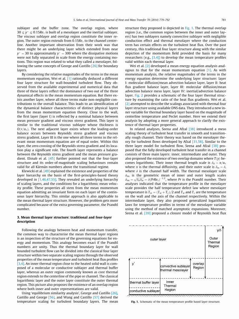
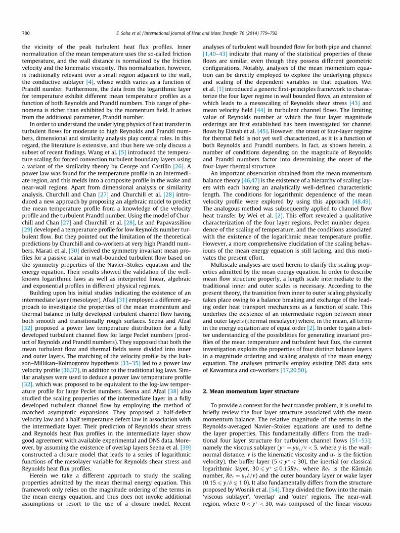
Fig. 1. Schematic of the mean temperature profile based layer structure.
S. Saha et al. / International Journal of Heat and Mass Transfer 70 (2014) 779–792 781
sublayer and the buffer zone. The overlap region, where30 K yþK 0:15Res is built of a mesolayer and the inertial sublayer.The viscous sublayer and overlap region constitute the inner re-gion. The outer region extends from 0:15Res to the channel center-line. Another important observation from their work was thatthere might be an underlying layer which extended from nearyþ ¼ 30 to approximately yþ ¼ 300 where the dissipative motionswere not fully separated in scale from the energy containing mo-tions. This region was related to what they called a mesolayer, fol-lowing the same concepts of George and Castillo [26] for boundarylayers.
By considering the relative magnitudes of the terms in the meanmomentum equation, Wei et al. [1] rationally deduced a differentfour layer structure for wall-bounded turbulent flow. They ob-served from the available experimental and numerical data thatthree of these layers reflect the dominance of two out of the threedynamical effects in the mean momentum equation. But there ex-ists another layer, where all three terms make non-negligible con-tributions to the overall balance. This leads to an identification ofthe dynamical balance characteristics of distinct physical layersfrom the mean momentum equation theory. Close to the wall,the first layer (layer I) is reflected by a nominal balance betweenmean pressure gradient and viscous stress gradient. This layer issimilar to the traditional viscous sublayer whose thickness isOðm=usÞ. The next adjacent layer exists where the leading-orderbalance occurs between Reynolds stress gradient and viscousstress gradient. Layer III is the one where all three terms in the rel-evant mean momentum equation are of equal order. Within thislayer, the zero crossing of the Reynolds stress gradient and its loca-tion play a significant role. The fourth layer represents a balancebetween the Reynolds stress gradient and the mean pressure gra-dient. Elsnab et al. [45] further pointed out that the four-layerstructure and its order-of-magnitude scaling behaviours remainvalid for all Kármán numbers above the transitional regime.
Klewicki et al. [49] explained the existence and properties of thelayer hierarchy on the basis of the first-principles-based theorydeveloped in [1,46,47,55]. They revealed an underlying hierarchyof scaling layers, and the conditions for a logarithmic mean veloc-ity profile. These properties all stem from the mean momentumequation admitting an invariant form on each layer of the contin-uous layer hierarchy. This similar approach is also applicable tothe mean thermal layer structure. However, the problem gets morecomplicated because of the extra governing parameter, the Prandtlnumber.
3. Mean thermal layer structure: traditional and four-layerdescription
Following the analogy between heat and momentum transfer,the common way to characterise the mean thermal layer regionsis an inspection of the structure of the governing equations for en-ergy and momentum. This analogy becomes exact if the Prandtlnumbers are unity. Thus the thermal boundary layer for wallbounded turbulent flow can be divided into the classical four layerstructure within two separate scaling regions through the observedproperties of the mean temperature and turbulent heat flux profiles[3,4]. An inner thermal region close to the heated solid wall is com-posed of a molecular or conductive sublayer and thermal bufferlayer, whereas an outer region commonly known as core thermalregion extends to the centerline of the pipe or channel. The classicallogarithmic layer and the outer layer constitute the outer thermalregion. This picture also proposes the existence of an overlap regionwhere both inner and outer representations are valid.
Using ‘equilibrium similarity analysis’, George and Castillo [26],Castillo and George [56], and Wang and Castillo [57] derived thetemperature scaling for turbulent boundary layers. The mean
structure they proposed is depicted in Fig. 1. The thermal overlapregion (i.e., the common region between the inner and outer lay-ers) has two sublayers namely convective sublayer with negligibleconduction effect and thermal mesolayer where the conductionterm has certain effects on the turbulent heat flux. Over the pastcentury, this traditional four layer structure along with the similardepiction of the momentum field provided the basis for manyresearchers (e.g., [3,4]) to develop the mean temperature profilesvalid within each thermal layer.
Wei et al. [2] developed a mean energy equation analysis anal-ogous to that for the mean momentum equation [1]. As withmomentum analysis, the relative magnitudes of the terms in theenergy equation determine the underlying layer structure: layerI: molecular diffusion/mean advection balance layer, layer II: heatflux gradient balance layer, layer III: molecular diffusion/meanadvection balance meso layer, layer IV: inertial/advection balancelayer. Fig. 2 provides a schematic of the four layer thermal struc-ture by examining the ratio of the heat flux gradients. Wei et al.[2] attempted to describe the scalings associated with thermal fourlayer structure using available DNS data. They introduced a new in-ner variable for thermal boundary layer based on the magnitude ofcenterline temperature and Peclet number. Here we extend theiranalysis by adopting a more general approach to clarify the exis-tence of thermal layer properties.
In related analyses, Seena and Afzal [38] introduced a mesoscaling theory of turbulent heat transfer in smooth and transition-ally rough channel. Their theory was based on the mesolayer the-ory for turbulent flows developed by Afzal [31,58]. Similar to thethree layer model for turbulent flow, Seena and Afzal [38] pro-posed that the fully developed turbulent heat transfer in a channelconsists of three main layers: inner, intermediate and outer. Theyalso proposed the existence of two overlap domains where TðyÞ be-comes logarithmic. Their inner thermal length scale is dti ¼ a=us
where a is the thermal diffusivity, and their outer scale is dto ¼ d,where d is the channel half width. The thermal mesolayer scaledtm is the geometric mean of inner and outer length scalesdtm ¼
ffiffiffiffiffiffiffiffiffiffiffidtidtop
¼ d PrResð Þ�1=2, where Pr is the Prandtl number. Theiranalyses indicated that the temperature profile in the mesolayerscale provides the half temperature defect law where mesolayertemperature is Tm ¼ Tw þ Tcð Þ=2 and Tw and Tc are the temperatureon the wall and the axis of the channel respectively. Within theintermediate layer, they also proposed generalized logarithmiclaws for temperature profiles in terms of the mesolayer variableusing the method of matched asymptotic expansions. Moreover,Seena et al. [39] proposed a closure model of Reynolds heat flux
Fig. 2. Sketch of the four layers of turbulent heat transfer in canonical flows for onePeclet number; layer I is the molecular diffusion/mean advection balance layer,layer II is the heat flux gradient balance layer, layer III is the molecular diffusion/mean advection balance meso layer and layer IV is the inertial/advection balancelayer. Note that the layer III is also called the balance breaking layer where theturbulent heat flux gradient crosses through zero.
782 S. Saha et al. / International Journal of Heat and Mass Transfer 70 (2014) 779–792
as a function of a series of logarithmic functions in the mesolayervariable. Distinct from Afzal and co-workers, the present analysesdo not assume overlap layers and do not employ asymptoticexpansions.
The mean energy balance equation is governed by the balancebetween the molecular diffusion, turbulent transport and meanstreamwise advection. Due to a balance breaking and exchangeof these mechanisms, the intermediate region (thermal mesolayer)exists between inner and outer layers where, in the mean, all thesethree terms are nearly in balance. Finding the appropriate lengthscales that allow the construction of a self-consistent invariantform of the appropriate leading order equation on the inner, outerand intermediate domains is inherently a two parameter problem.Herein we present a systematic study that clarifies the nature ofthe underlying parameter dependencies.
4. Derivation of mathematical model
4.1. Mean energy balance equation
The present analysis begins with the appropriate form of themean energy equation. The analysis considers statistically station-ary, fully developed, incompressible, pressure driven turbulentflow and heat transfer in a two-dimensional channel. The fluidproperties are assumed to be constant. Temperature is treated asa passive scalar.
The three-dimensional instantaneous energy balance equationfor an incompressible flow with constant properties and negligibleviscous heating is given by
@~T@~tþ ~ux
@~T@xþ ~uy
@~T@yþ ~uz
@~T@z¼ a
@2~T@x2 þ
@2 ~T@y2 þ
@2~T@z2
" #; ð1Þ
where ~ux, ~uy and ~uz are the instantaneous velocity components inthe x, y and z directions, ~T is the instantaneous temperature, ~t istime and q is the mass density of fluid. The terms in the aboveenergy balance equation are decomposed into their mean andfluctuating parts using:
~ux ¼ U þ u; ~uy ¼ V þ v ; ~uz ¼W þw; and ~T ¼ T þ t; ð2Þ
where U, V, W are the mean velocity components in x, y and z direc-tions, u, v, and w are the corresponding fluctuating velocity compo-nents, T is the mean temperature and t is the correspondingfluctuating temperature. The temporal average of the product ut,vt and wt are denoted by huti, hvti and hwti, respectively. Theresulting time-averaged energy balance equation is
U@T@xþV
@T@yþW
@T@z¼a
@2T@x2 þ
@2T@y2þ
@2T@z2
" #�@ uth i
@x�@ vth i
@y�@ wth i
@z:
ð3Þ
For the given flow, (3) reduces to
U@T@x¼ a
@2T@x2 þ
@2T@y2
" #� @ vth i
@y: ð4Þ
In fully developed heat transfer, the mean temperature is a linearlyincreasing function of x and the rate of increase can be determinedby applying an energy balance to a differential element of the chan-nel. This yields
@T@x¼ qw
qCpUbd; ð5Þ
where, qw ¼ kð@T=@yÞw is the heat flux applied at the upper and bot-tom walls, k is the thermal conductivity, Cp is the specific heat andUb ¼ 1
d
R d0 UðyÞdy is the bulk mean velocity. The right hand side of (5)
is constant, and using the definition of Prandtl number, Pr ¼ m=a,the averaged energy balance equation becomes
qwUqCpUbd
¼ mPr
@2T@y2 �
@ vth i@y
: ð6Þ
Eq. (6) contains two unknown functions, mean temperature T andturbulent heat flux hvti. These are the quantities of primary interest.The boundary conditions at the channel wall, y ¼ 0, are
U ¼ u ¼ v ¼ t ¼ 0;@T@y¼ qw
k; ð7Þ
and at the centerline, y ¼ d, are
@T@y¼ vth i ¼ 0: ð8Þ
4.2. Normalizations
The friction velocity us, inner length for momentum, m=us, andouter length, d, are often considered as the basic normalizationparameters for turbulent flow problems. Moreover, the normaliza-tion parameters used herein for the heat transfer problem are thefriction temperature Ts ¼ qw=qCpus and an inner normalizedlength mPr�b=us generalized by considering a power law Prandtlnumber effect. In addition to these parameters, the non-dimen-sional temperature Hþ ¼ ð Twh i � TÞ=Ts gives (6) its convectionalinner normalized form,
1Pr
d2Hþ
dyþ2 þdTþhdyþþ e2 Uþ
Uþb¼ 0; ð9Þ
where Tþh ¼ �hvtiþ is the inner normalized turbulent heat flux. Thesmall parameter e is defined by
e ¼ 1ffiffiffiffiffiffidþp ; ð10Þ
where dþ ¼ usd=m is the Reynolds number (Kármán number), so thate! 0 as dþ ! 1. The outer normalized form of (6) is found by using
S. Saha et al. / International Journal of Heat and Mass Transfer 70 (2014) 779–792 783
the channel half-width d to normalize the wall normal distanceg ¼ y=d. This gives
e2
Prd2Hþ
dg2 þdTþhdgþ Uþ
Uþb¼ 0: ð11Þ
The boundary conditions at the channel wall, yþ ¼ 0, are
Uþ ¼ Hþ ¼ Tþh ¼ 0;dHþ
dyþ¼ Pr; ð12Þ
and at the centerline, yþ ¼ dþ, are
dHþ
dyþ¼ Tþh ¼ 0: ð13Þ
Both Pr and dþ play important roles in the following analysis. Eq. (9)implies a fully developed thermal field hence there is no depen-dence on axial direction. At sufficiently high Res, Uþ=Uþb is Oð1Þfor all values of yþ values beyond the peak in the Reynolds shearstress, and in this region Uþ=Uþb ! 1 as dþ ! 1. Note that thewall-normal distance is still normalised by the length scale of theviscous sublayer, m=us.
Wei et al. [2] developed an alternative normalized form of (6)by introducing the parameter r which is a function of dþ and Pecletnumber Pes ¼ Prdþ, and is defined as
r2 dþ; Pes� �
¼maxHþ
Prdþ
� �¼
Hþ��g¼1
Pes¼ Hþm
Pes: ð14Þ
Given this, a new r-dependent temperature variable w follows andis expressed as
w ¼ Hþ
Pesr2 : ð15Þ
This renders w ¼ Oð1Þ near the channel center and r� 1. The cor-responding outer normalized form of (9) is
r2 d2wdg2 þ
dTþhdgþ R gð Þ ¼ 0; ð16Þ
where RðgÞ ¼ Uþ=Uþb is the scaled advection function. By employingthe generic inner-outer variable relation, Wei et al. [2] defined anew inner scaled distance yr as
yr ¼gr2 ; ð17Þ
which generates a scaled advection functionRrðyrÞ ¼ RðgðyrÞÞ ¼ Rðr2yrÞ. This yields a new ‘inner’ form of (6),
d2w
dy2r
þ dTþhdyrþ r2Rr yrð Þ ¼ 0; ð18Þ
Aþ Bþ C ¼ 0;
where the relationship between the inner and outer coordinates isgiven by (17). The boundary conditions on (18) are
w ¼ Tþh ¼ 0;dwdyr
0ð Þ ¼ 1 at yr ¼ 0: ð19Þ
In the following analysis, we examine three alternative forms of (6),distinct from (18), in order to clarify the dependences on Pr. Weintroduce a new inner variable yþh ¼ Prbyþ. Its use yields three casesfor (6).
Case I.
d2Hþ
dyþ2h
þdTþ/dyþhþ /2Rh yþh
� �¼ 0; ð20Þ
Aþ Bþ C ¼ 0;
where Tþ/ ¼ Pr1�bTþh and the small parameter / is defined by
/ ¼ 1ffiffiffiffiffiffiffiffiffiffiffiffiffiffiffiffiffiffidþPr2b�1
p : ð21Þ
The thermal boundary conditions at the channel wall, yþh ¼ 0, are
Hþ ¼ 0;dHþ
dyþh¼ Pr1�b: ð22Þ
Here Hþ is not scaled by Pr, and both the boundary condition andthe advection term depend on Pr. If we consider b ¼ 1, then thenew inner scaled energy equation takes the form of the traditionalinner Eq. (9).
Case II.
d2Uþ
dyþ2h
þ dTþhdyþhþ /2Rh yþh
� �¼ 0; ð23Þ
Aþ Bþ C ¼ 0;
where Uþ ¼ Prb�1Hþ and the small parameter / is defined by
/ ¼ 1ffiffiffiffiffiffiffiffiffiffiffiffidþPrb
p : ð24Þ
The thermal boundary conditions at the channel wall, yþh ¼ 0, are
Uþ ¼ 0;dUþ
dyþh¼ 1: ð25Þ
Here Tþh is not scaled by Pr, and nor are the boundary conditions atthe wall. There is, however, a Prandtl number dependence in theadvection term.
Case III.
d2Uþ
dyþ2h
þdTþ/dyþhþ /2Rh yþh
� �¼ 0; ð26Þ
Aþ Bþ C ¼ 0;
where Uþ ¼ Pr2b�1Hþ, Tþ/ ¼ PrbTþh and the small parameter / isdefined by
/ ¼ 1ffiffiffiffiffiffidþp : ð27Þ
The thermal boundary conditions at the channel wall are
Uþ ¼ 0;dUþ
dyþh¼ Prb: ð28Þ
Here there is no Pr dependence in the small parameter.All three cases of above suggest that 1=/2 must be large enough
to maintain a turbulent state for flow and heat transfer. Threedistinct mechanisms are clearly apparent in Eqs. (18), (20), (23),(26): A = gradient of the molecular diffusion flux, B = gradient ofthe turbulent transport flux and C = mean streamwise advection.
5. Data sets
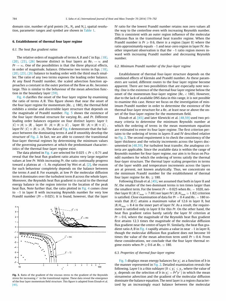
Herein we use the DNS data sets from Kawamura’s group[17,20,50] for 0:025 6 Pr 6 10:0 and 180 6 Res 6 1020. Optimally,one would like to have a high Res condition and then vary Pr. Ow-ing to existing computational limitations, high Pr and high Res are,however, not simultaneously possible. Thus, a single Kármánnumber near the onset of the four layer momentum structure(Res ¼ 180) is selected to study Pr effects, see Fig. 3 [45]. The
784 S. Saha et al. / International Journal of Heat and Mass Transfer 70 (2014) 779–792
domain size, number of grid points (Nx, Ny and Nz), spatial resolu-tion, parameter ranges and symbol are shown in Table 1.
6. Establishment of thermal four layer regime
6.1. The heat flux gradient ratios
The relative orders of magnitude of terms A, B and C in Eqs. (18),(20), (23), (26) become distinct in four layers as Res !1 andPr !1. One of the possibilities is that the three physical effects,in order of magnitude, balance. Otherwise two terms in Eqs. (18),(20), (23), (26) balance to leading order with the third much smal-ler. The ratio of any two terms exposes the leading order balance.At any fixed Prandtl number, the scaled advection function ap-proaches a constant in the outer portion of the flow as Res becomeslarge. This is similar to the behaviour of the mean advection func-tion in the boundary layer [59].
Fig. 4 clarifies the onset of the four layer regime by examiningthe ratio of terms A=B. This figure shows that near the onset ofthe four layer regime for momentum (Res K 180), the thermal fieldexhibits a similar and discernible layer structure that depends onthe magnitude of Prandtl number. Fig. 5 shows the existence ofthe four layer thermal structure for varying Res and Pr. Differentleading order balances organize on four distinct layers: layer I:jCj ffi jAj � jBj , layer II: jAj ffi jBj � jCj , layer III: jAj ffi jBj ffi jCj ,layer IV: jCj ffi jBj � jAj. The data of Fig. 4 demonstrate that the bal-ance between the dominating terms A and B smoothly develop thestructure of Fig. 2. In fact, we are able to connect the transitionalfour-layer thermal regimes by determining the minimum valuesof the governing parameters at which the predominant character-istics of the thermal four-layer regime exist.
The data plotted in Fig. 4 are selected for 0:025 6 Pr 6 0:71 andreveal that the heat flux gradient ratio attains very large negativevalues at low Pr. With increasing Pr, the ratio continually progresstoward a plateau at �1. As explained by Wei et al. [2], the reasonfor such behaviour completely depends on the balance betweenthe terms A and B. For example, at low Pr the molecular diffusionterm A dominates over the turbulent term B across the whole layer.Moreover, the Reynolds heat flux gradient is crucial to the thermalenergy balance in the region interior to the location of the peakheat flux. Note further that, the ratio plotted in Fig. 4 comes closeto �1 in layer II with increasing Reynolds number for very lowPrandtl number (Pr ¼ 0:025). It is found, however, that the layer
Fig. 3. Ratio of the gradient of the viscous stress to the gradient of the Reynoldsstress for increasing dþ in the transitional regime. These data reveal the emergenceof the four layer momentum field structure. This figure is adapted from Elsnab et al.[45].
IV ratio for the lowest Prandtl number retains non zero values allthe way to the centerline even with increasing Reynolds number.This is consistent with an outer region influence of the moleculardiffusion flux in the transitional heat transfer regime. When thePrandtl number is Pr P 0:6, there is a region (layer II) where theratio approximately equals�1 and near-zero region in layer IV. An-other important observation is that the �1 ratio region moves in-ward with increasing Prandtl number and decreasing Reynoldsnumber.
6.2. Minimum Prandtl number of the four-layer regime
Establishment of thermal four-layer structure depends on thecombined effects of Kármán and Prandtl number. As these param-eters are varied, different routes to the four layer regime becomeapparent. There are two possibilities that are especially note wor-thy. One is the existence of the thermal four layer regime below theonset of the momentum four-layer regime (Res < 180). However,due to the lack of available DNS data in this range, it is not possibleto examine this case. Hence we focus on the investigation of min-imum Prandtl number in order to determine the existence of thethermal four-layer structure for a Res at least near or above the on-set of the four-layer regime for the momentum field.
Elsnab et al. [45] and later Klewicki et al. [48,59] used two pri-mary criteria to determine the minimum Reynolds number atwhich the ordering of terms in the mean momentum equationare estimated to enter its four layer regime. The first criterion per-tains to the ordering of terms in layers II and IV described relativeto Fig. 2. The second requirement is to check the consistency of thelayer thickness and the velocity increments across the layers doc-umented in [48,59]. For turbulent heat transfer, the analogous cri-teria are applicable. Since the available data is within the range ofReynolds number for four-layer regime, our aim is to focus on Pra-ndtl numbers for which the ordering of terms satisfy the thermalfour-layer structure. The thermal layer scaling properties in termsof the layer width and temperature increments across the layersare at present, not known analytically. Thus, we concentrate onthe minimum Prandtl number for the establishment of thermalfour layer regime for Res J 180.
Following Elsnab et al. [45], we assumed that both in layer II andIV, the smaller of the two dominant terms is ten times larger thanthe smallest term. For the lowest Pr ¼ 0:025 when Res ¼ 1020, nei-ther layer II (jB=Cjmax ’ 7:69) nor layer IV (jB=Ajmax ’ 1:82) criterionis satisfied. Close examination of data for Pr ¼ 0:4 and Res ¼ 180 re-veals that jB=Cj attains a maximum value of 12.6 in layer II, butjB=Ajmax ’ 8:4 in the inner part of layer IV. As a result, the require-ment is satisfied only in layer II for this Pr. On the other hand, theheat flux gradient ratios barely satisfy the layer IV criterion atPr ’ 0:6, where the magnitude of the Reynolds heat flux gradientfirst attains 12.3 times the magnitude of the molecular diffusionflux gradient near the centre of layer IV. Similarly, the heat flux gra-dient ratio A=B in Fig. 4 rapidly attains a value in near �1 in layer II,though the molecular diffusion flux gradient does not become 10times the value of the mean advection term until Pr ’ 0:4. Fromthese considerations, we conclude that the four layer thermal re-gime exists when Pr J 0:6 at Res ’ 180.
6.3. Properties of thermal four-layer regime
Fig. 5 displays mean energy balances for yþh as a function of b inthe manner represented in Fig. 2. Detailed examination reveals thefollowing. Layer I is a thin sublayer (0 6 yþh 6 yc , where the value ofyc depends on the selection of b in yþh ¼ Prbyþ) in which the meanstreamwise advection and the gradient of the molecular diffusiondominate the balance equation. The next layer is a region character-ized by an increasingly exact balance between the molecular
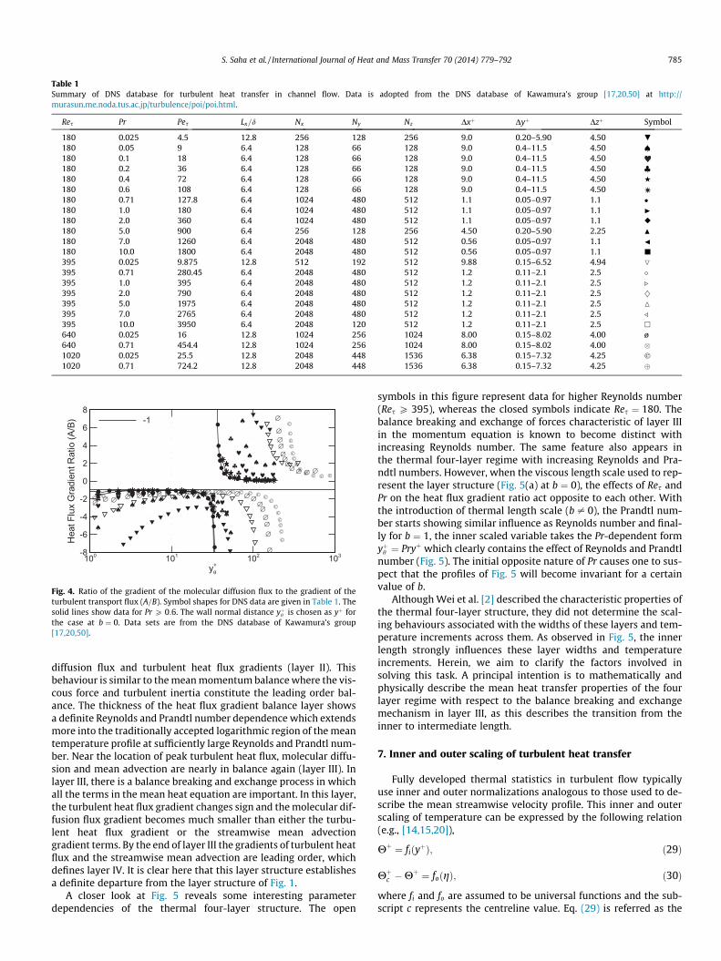
Table 1Summary of DNS database for turbulent heat transfer in channel flow. Data is adopted from the DNS database of Kawamura’s group [17,20,50] at http://murasun.me.noda.tus.ac.jp/turbulence/poi/poi.html.
Res Pr Pes Lx=d Nx Ny Nz Dxþ Dyþ Dzþ Symbol
180 0.025 4.5 12.8 256 128 256 9.0 0.20–5.90 4.50 .
180 0.05 9 6.4 128 66 128 9.0 0.4–11.5 4.50 €180 0.1 18 6.4 128 66 128 9.0 0.4–11.5 4.50180 0.2 36 6.4 128 66 128 9.0 0.4–11.5 4.50 |180 0.4 72 6.4 128 66 128 9.0 0.4–11.5 4.50 H
180 0.6 108 6.4 128 66 128 9.0 0.4–11.5 4.50180 0.71 127.8 6.4 1024 480 512 1.1 0.05–0.97 1.1 �180 1.0 180 6.4 1024 480 512 1.1 0.05–0.97 1.1 I
180 2.0 360 6.4 1024 480 512 1.1 0.05–0.97 1.1 r
180 5.0 900 6.4 256 128 256 4.50 0.20–5.90 2.25 N
180 7.0 1260 6.4 2048 480 512 0.56 0.05–0.97 1.1 J
180 10.0 1800 6.4 2048 480 512 0.56 0.05–0.97 1.1 j
395 0.025 9.875 12.8 512 192 512 9.88 0.15–6.52 4.94 O
395 0.71 280.45 6.4 2048 480 512 1.2 0.11–2.1 2.5 �395 1.0 395 6.4 2048 480 512 1.2 0.11–2.1 2.5 .
395 2.0 790 6.4 2048 480 512 1.2 0.11–2.1 2.5 }395 5.0 1975 6.4 2048 480 512 1.2 0.11–2.1 2.5 M
395 7.0 2765 6.4 2048 480 512 1.2 0.11–2.1 2.5 /
395 10.0 3950 6.4 2048 120 512 1.2 0.11–2.1 2.5 �
640 0.025 16 12.8 1024 256 1024 8.00 0.15–8.02 4.00 ø640 0.71 454.4 12.8 1024 256 1024 8.00 0.15–8.02 4.00 �1020 0.025 25.5 12.8 2048 448 1536 6.38 0.15–7.32 4.25 �1020 0.71 724.2 12.8 2048 448 1536 6.38 0.15–7.32 4.25
♠
♠ ♠ ♠ ♠ ♠ ♠ ♠ ♠ ♠ ♠♠
♠
♠
♠♠
♠ ♠ ♠
♥♥ ♥ ♥ ♥ ♥ ♥ ♥ ♥ ♥
♥♥
♥♥♥♥ ♥ ♥
♣ ♣ ♣ ♣ ♣ ♣ ♣ ♣ ♣ ♣
♣
♣
♣♣ ♣ ♣ ♣ ♣
∅ ∅ ∅ ∅ ∅ ∅ ∅ ∅ ∅ ∅ ∅ ∅ ∅ ∅ ∅ ∅ ∅∅∅∅∅∅
∅
∅
∅∅∅∅∅∅∅ ∅ ∅ ∅
© © © © © © © © © © © © © © © © © © ©©
©©©©©©
©
©©©©©©
©© © © ©
yθ+
HeatFluxGradientRatio(A/B)
100 101 102 103-8
-6
-4
-2
0
2
4
6
8-1
Fig. 4. Ratio of the gradient of the molecular diffusion flux to the gradient of theturbulent transport flux (A=B). Symbol shapes for DNS data are given in Table 1. Thesolid lines show data for Pr P 0:6. The wall normal distance yþh is chosen as yþ forthe case at b ¼ 0. Data sets are from the DNS database of Kawamura’s group[17,20,50].
S. Saha et al. / International Journal of Heat and Mass Transfer 70 (2014) 779–792 785
diffusion flux and turbulent heat flux gradients (layer II). Thisbehaviour is similar to the mean momentum balance where the vis-cous force and turbulent inertia constitute the leading order bal-ance. The thickness of the heat flux gradient balance layer showsa definite Reynolds and Prandtl number dependence which extendsmore into the traditionally accepted logarithmic region of the meantemperature profile at sufficiently large Reynolds and Prandtl num-ber. Near the location of peak turbulent heat flux, molecular diffu-sion and mean advection are nearly in balance again (layer III). Inlayer III, there is a balance breaking and exchange process in whichall the terms in the mean heat equation are important. In this layer,the turbulent heat flux gradient changes sign and the molecular dif-fusion flux gradient becomes much smaller than either the turbu-lent heat flux gradient or the streamwise mean advectiongradient terms. By the end of layer III the gradients of turbulent heatflux and the streamwise mean advection are leading order, whichdefines layer IV. It is clear here that this layer structure establishesa definite departure from the layer structure of Fig. 1.
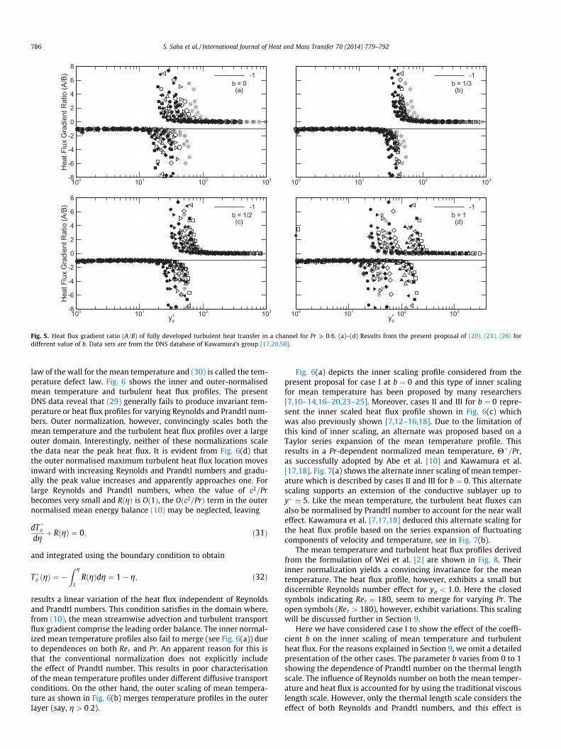
A closer look at Fig. 5 reveals some interesting parameterdependencies of the thermal four-layer structure. The open
symbols in this figure represent data for higher Reynolds number(Res P 395), whereas the closed symbols indicate Res ¼ 180. Thebalance breaking and exchange of forces characteristic of layer IIIin the momentum equation is known to become distinct withincreasing Reynolds number. The same feature also appears inthe thermal four-layer regime with increasing Reynolds and Pra-ndtl numbers. However, when the viscous length scale used to rep-resent the layer structure (Fig. 5(a) at b ¼ 0), the effects of Res andPr on the heat flux gradient ratio act opposite to each other. Withthe introduction of thermal length scale (b – 0), the Prandtl num-ber starts showing similar influence as Reynolds number and final-ly for b ¼ 1, the inner scaled variable takes the Pr-dependent formyþh ¼ Pryþ which clearly contains the effect of Reynolds and Prandtlnumber (Fig. 5). The initial opposite nature of Pr causes one to sus-pect that the profiles of Fig. 5 will become invariant for a certainvalue of b.
Although Wei et al. [2] described the characteristic properties ofthe thermal four-layer structure, they did not determine the scal-ing behaviours associated with the widths of these layers and tem-perature increments across them. As observed in Fig. 5, the innerlength strongly influences these layer widths and temperatureincrements. Herein, we aim to clarify the factors involved insolving this task. A principal intention is to mathematically andphysically describe the mean heat transfer properties of the fourlayer regime with respect to the balance breaking and exchangemechanism in layer III, as this describes the transition from theinner to intermediate length.
7. Inner and outer scaling of turbulent heat transfer
Fully developed thermal statistics in turbulent flow typicallyuse inner and outer normalizations analogous to those used to de-scribe the mean streamwise velocity profile. This inner and outerscaling of temperature can be expressed by the following relation(e.g., [14,15,20]),
Hþ ¼ fiðyþÞ; ð29Þ
Hþc �Hþ ¼ foðgÞ; ð30Þ
where fi and fo are assumed to be universal functions and the sub-script c represents the centreline value. Eq. (29) is referred as the
⊗ ⊗ ⊗ ⊗ ⊗ ⊗ ⊗ ⊗ ⊗ ⊗ ⊗ ⊗ ⊗⊗
⊗
⊗
⊗
⊗⊗
⊗ ⊗ ⊗ ⊗ ⊗ ⊗ ⊗ ⊗ ⊗ ⊗⊕ ⊕ ⊕ ⊕ ⊕ ⊕ ⊕ ⊕ ⊕ ⊕ ⊕ ⊕ ⊕ ⊕
⊕⊕⊕
⊕
⊕
⊕⊕⊕
⊕ ⊕ ⊕ ⊕ ⊕ ⊕ ⊕ ⊕ ⊕ ⊕ ⊕
HeatFluxGradientRatio(A/B)
100 101 102 103-8
-6
-4
-2
0
2
4
6
8-1
b = 0(a)
⊗ ⊗ ⊗ ⊗ ⊗ ⊗ ⊗ ⊗ ⊗ ⊗ ⊗ ⊗ ⊗⊗
⊗
⊗
⊗
⊗⊗
⊗ ⊗ ⊗ ⊗ ⊗ ⊗ ⊗ ⊗ ⊗ ⊗⊕ ⊕ ⊕ ⊕ ⊕ ⊕ ⊕ ⊕ ⊕ ⊕ ⊕ ⊕ ⊕
⊕⊕⊕
⊕
⊕
⊕⊕⊕
⊕ ⊕ ⊕ ⊕ ⊕ ⊕ ⊕ ⊕ ⊕ ⊕ ⊕
100 101 102 103
-1b = 1/3(b)
⊗ ⊗ ⊗ ⊗ ⊗ ⊗ ⊗ ⊗ ⊗ ⊗ ⊗ ⊗⊗
⊗
⊗
⊗
⊗⊗
⊗ ⊗ ⊗ ⊗ ⊗ ⊗ ⊗ ⊗ ⊗ ⊗⊕ ⊕ ⊕ ⊕ ⊕ ⊕ ⊕ ⊕ ⊕ ⊕ ⊕ ⊕ ⊕
⊕⊕⊕
⊕
⊕
⊕⊕⊕
⊕ ⊕ ⊕ ⊕ ⊕ ⊕ ⊕ ⊕ ⊕ ⊕ ⊕
yθ+
HeatFluxGradientRatio(A/B)
100 101 102 103-8
-6
-4
-2
0
2
4
6
8-1
b = 1/2(c)
⊗ ⊗ ⊗ ⊗ ⊗ ⊗ ⊗ ⊗ ⊗ ⊗⊗
⊗
⊗
⊗
⊗⊗⊗ ⊗ ⊗ ⊗ ⊗ ⊗ ⊗ ⊗
⊕ ⊕ ⊕ ⊕ ⊕ ⊕ ⊕ ⊕ ⊕ ⊕ ⊕⊕⊕⊕
⊕
⊕
⊕⊕⊕⊕⊕ ⊕ ⊕ ⊕ ⊕ ⊕ ⊕ ⊕
yθ+100 101 102 103
-1b = 1(d)
Fig. 5. Heat flux gradient ratio (A=B) of fully developed turbulent heat transfer in a channel for Pr P 0:6. (a)–(d) Results from the present proposal of (20), (23), (26) fordifferent value of b. Data sets are from the DNS database of Kawamura’s group [17,20,50].
786 S. Saha et al. / International Journal of Heat and Mass Transfer 70 (2014) 779–792
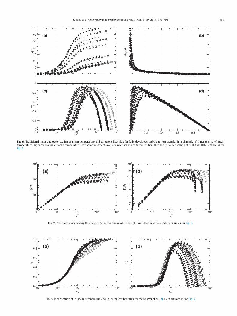
law of the wall for the mean temperature and (30) is called the tem-perature defect law. Fig. 6 shows the inner and outer-normalisedmean temperature and turbulent heat flux profiles. The presentDNS data reveal that (29) generally fails to produce invariant tem-perature or heat flux profiles for varying Reynolds and Prandtl num-bers. Outer normalization, however, convincingly scales both themean temperature and the turbulent heat flux profiles over a largeouter domain. Interestingly, neither of these normalizations scalethe data near the peak heat flux. It is evident from Fig. 6(d) thatthe outer normalised maximum turbulent heat flux location movesinward with increasing Reynolds and Prandtl numbers and gradu-ally the peak value increases and apparently approaches one. Forlarge Reynolds and Prandtl numbers, when the value of e2=Prbecomes very small and RðgÞ is Oð1Þ, the Oðe2=PrÞ term in the outernormalised mean energy balance (10) may be neglected, leaving
dTþhdgþ R gð Þ ¼ 0; ð31Þ
and integrated using the boundary condition to obtain
Tþh gð Þ ¼ �Z g
1R gð Þdg ¼ 1� g; ð32Þ
results a linear variation of the heat flux independent of Reynoldsand Prandtl numbers. This condition satisfies in the domain where,from (10), the mean streamwise advection and turbulent transportflux gradient comprise the leading order balance. The inner normal-ized mean temperature profiles also fail to merge (see Fig. 6(a)) dueto dependences on both Res and Pr. An apparent reason for this isthat the conventional normalization does not explicitly includethe effect of Prandtl number. This results in poor characterisationof the mean temperature profiles under different diffusive transportconditions. On the other hand, the outer scaling of mean tempera-ture as shown in Fig. 6(b) merges temperature profiles in the outerlayer (say, g > 0:2).
Fig. 6(a) depicts the inner scaling profile considered from thepresent proposal for case I at b ¼ 0 and this type of inner scalingfor mean temperature has been proposed by many researchers[7,10–14,16–20,23–25]. Moreover, cases II and III for b ¼ 0 repre-sent the inner scaled heat flux profile shown in Fig. 6(c) whichwas also previously shown [7,12–16,18]. Due to the limitation ofthis kind of inner scaling, an alternate was proposed based on aTaylor series expansion of the mean temperature profile. Thisresults in a Pr-dependent normalized mean temperature, Hþ=Pr,as successfully adopted by Abe et al. [10] and Kawamura et al.[17,18]. Fig. 7(a) shows the alternate inner scaling of mean temper-ature which is described by cases II and III for b ¼ 0. This alternatescaling supports an extension of the conductive sublayer up toyþ ’ 5. Like the mean temperature, the turbulent heat fluxes canalso be normalised by Prandtl number to account for the near walleffect. Kawamura et al. [7,17,18] deduced this alternate scaling forthe heat flux profile based on the series expansion of fluctuatingcomponents of velocity and temperature, see in Fig. 7(b).
The mean temperature and turbulent heat flux profiles derivedfrom the formulation of Wei et al. [2] are shown in Fig. 8. Theirinner normalization yields a convincing invariance for the meantemperature. The heat flux profile, however, exhibits a small butdiscernible Reynolds number effect for yr < 1:0. Here the closedsymbols indicating Res ¼ 180, seem to merge for varying Pr. Theopen symbols (Res > 180), however, exhibit variations. This scalingwill be discussed further in Section 9.
Here we have considered case I to show the effect of the coeffi-cient b on the inner scaling of mean temperature and turbulentheat flux. For the reasons explained in Section 9, we omit a detailedpresentation of the other cases. The parameter b varies from 0 to 1showing the dependence of Prandtl number on the thermal lengthscale. The influence of Reynolds number on both the mean temper-ature and heat flux is accounted for by using the traditional viscouslength scale. However, only the thermal length scale considers theeffect of both Reynolds and Prandtl numbers, and this effect is
⊗ ⊗ ⊗ ⊗ ⊗ ⊗ ⊗ ⊗ ⊗ ⊗ ⊗ ⊗ ⊗ ⊗ ⊗ ⊗ ⊗ ⊗ ⊗
⊕ ⊕ ⊕ ⊕ ⊕ ⊕ ⊕ ⊕ ⊕ ⊕ ⊕ ⊕ ⊕ ⊕ ⊕ ⊕ ⊕ ⊕ ⊕ ⊕ ⊕
Θ+
0
10
20
30
40
50
60
70
(a)
⊗⊗⊗⊗
⊗ ⊗ ⊗ ⊗ ⊗ ⊗ ⊗ ⊗ ⊗ ⊗ ⊗ ⊗ ⊗ ⊗ ⊗ ⊗ ⊗ ⊗ ⊗ ⊗ ⊗ ⊗
⊕⊕⊕⊕
⊕ ⊕ ⊕ ⊕ ⊕ ⊕ ⊕ ⊕ ⊕ ⊕ ⊕ ⊕ ⊕ ⊕ ⊕ ⊕ ⊕ ⊕ ⊕ ⊕ ⊕ ⊕ ⊕
Θc+-Θ
+
(b)
⊗ ⊗ ⊗ ⊗ ⊗ ⊗⊗
⊗⊗⊗⊗⊗⊗⊗⊗⊗⊗⊗
⊗⊗
⊗ ⊗ ⊗ ⊗⊗
⊗⊗
⊗⊗⊗⊗⊗⊗⊗⊗⊗⊗⊗⊗⊗⊗⊗⊕ ⊕ ⊕ ⊕ ⊕ ⊕
⊕⊕
⊕⊕
⊕⊕⊕
⊕⊕⊕⊕⊕
⊕⊕
⊕ ⊕ ⊕ ⊕ ⊕⊕
⊕⊕
⊕⊕⊕⊕⊕⊕⊕⊕⊕⊕⊕⊕⊕⊕⊕⊕
y+
T θ+
10-1 100 101 102 1030
0.2
0.4
0.6
0.8
1
(c)
⊗⊗⊗
⊗⊗⊗⊗⊗⊗⊗⊗⊗⊗⊗⊗⊗
⊗ ⊗ ⊗ ⊗ ⊗⊗
⊗⊗ ⊗ ⊗
⊗⊗
⊗⊗
⊗⊗
⊗⊗
⊗⊗
⊗⊗
⊗⊗
⊗⊗
⊗⊕⊕⊕⊕⊕
⊕
⊕⊕
⊕⊕⊕⊕⊕⊕⊕⊕ ⊕ ⊕ ⊕ ⊕ ⊕
⊕ ⊕⊕
⊕⊕ ⊕ ⊕
⊕⊕
⊕⊕
⊕⊕
⊕⊕
⊕⊕
⊕⊕
⊕⊕ ⊕
⊕⊕
η0 0.2 0.4 0.6 0.8 1
(d)
Fig. 6. Traditional inner and outer scaling of mean temperature and turbulent heat flux for fully developed turbulent heat transfer in a channel. (a) Inner scaling of meantemperature, (b) outer scaling of mean temperature (temperature defect law), (c) inner scaling of turbulent heat flux and (d) outer scaling of heat flux. Data sets are as forFig. 5.
⊗
⊗
⊗⊗
⊗⊗
⊗⊗
⊗⊗
⊗ ⊗ ⊗ ⊗ ⊗ ⊗ ⊗ ⊗ ⊗ ⊗ ⊗ ⊗
⊕
⊕⊕
⊕⊕
⊕⊕
⊕⊕
⊕⊕ ⊕ ⊕ ⊕ ⊕ ⊕ ⊕ ⊕ ⊕ ⊕ ⊕ ⊕ ⊕
y+
Θ+ /Pr
10-1 100 101 102 1030-1
100
101
102
(a)
⊗
⊗
⊗⊗
⊗⊗
⊗⊗
⊗⊗
⊗ ⊗ ⊗ ⊗ ⊗ ⊗ ⊗ ⊗ ⊗ ⊗ ⊗⊗⊗⊗⊗
⊕
⊕
⊕⊕
⊕⊕
⊕⊕
⊕⊕
⊕⊕ ⊕ ⊕ ⊕ ⊕ ⊕ ⊕ ⊕ ⊕ ⊕ ⊕ ⊕
⊕⊕⊕⊕
y+
T θ+ /Pr
10-1 100 101 102 10310-6
10-5
10-4
10-3
10-2
10-1
100
101
(b)
Fig. 7. Alternate inner scaling (log–log) of (a) mean temperature and (b) turbulent heat flux. Data sets are as for Fig. 5.
⊗ ⊗ ⊗⊗
⊗⊗
⊗⊗
⊗⊗
⊗⊗
⊗⊗
⊗⊗
⊗⊗
⊗⊗
⊗⊗
⊗⊗
⊗⊗
⊕ ⊕ ⊕ ⊕ ⊕ ⊕⊕
⊕⊕
⊕⊕
⊕⊕
⊕⊕
⊕⊕
⊕⊕ ⊕
⊕⊕
⊕⊕
⊕⊕
⊕⊕
yσ
ψ
10-2 10-1 100 101 1020.0
0.2
0.4
0.6
0.8
1.0
(a)
⊗ ⊗ ⊗ ⊗ ⊗ ⊗⊗
⊗⊗⊗⊗⊗⊗⊗⊗⊗⊗⊗
⊗⊗
⊗ ⊗ ⊗ ⊗⊗
⊗⊗
⊗⊗⊗⊗⊗⊗⊗⊗⊗⊗⊗⊗⊗⊗⊗⊗⊕ ⊕ ⊕ ⊕ ⊕ ⊕
⊕⊕
⊕⊕
⊕⊕⊕⊕
⊕⊕⊕⊕⊕
⊕⊕
⊕ ⊕ ⊕ ⊕ ⊕⊕
⊕⊕
⊕⊕⊕⊕⊕⊕⊕⊕⊕⊕⊕⊕⊕⊕⊕⊕⊕
yσ
T+ θ
10-2 10-1 100 101 102
(b)
Fig. 8. Inner scaling of (a) mean temperature and (b) turbulent heat flux following Wei et al. [2]. Data sets are as for Fig. 5.
S. Saha et al. / International Journal of Heat and Mass Transfer 70 (2014) 779–792 787
788 S. Saha et al. / International Journal of Heat and Mass Transfer 70 (2014) 779–792
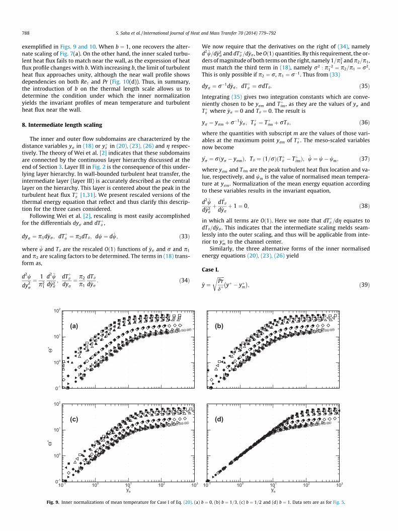
exemplified in Figs. 9 and 10. When b ¼ 1, one recovers the alter-nate scaling of Fig. 7(a). On the other hand, the inner scaled turbu-lent heat flux fails to match near the wall, as the expression of heatflux profile changes with b. With increasing b, the limit of turbulentheat flux approaches unity, although the near wall profile showsdependencies on both Res and Pr (Fig. 10(d)). Thus, in summary,the introduction of b on the thermal length scale allows us todetermine the condition under which the inner normalizationyields the invariant profiles of mean temperature and turbulentheat flux near the wall.
8. Intermediate length scaling
The inner and outer flow subdomains are characterized by thedistance variables yr in (18) or yþh in (20), (23), (26) and g respec-tively. The theory of Wei et al. [2] indicates that these subdomainsare connected by the continuous layer hierarchy discussed at theend of Section 3. Layer III in Fig. 2 is the consequence of this under-lying layer hierarchy. In wall-bounded turbulent heat transfer, theintermediate layer (layer III) is accurately described as the centrallayer on the hierarchy. This layer is centered about the peak in theturbulent heat flux Tþh [1,31]. We present rescaled versions of thethermal energy equation that reflect and thus clarify this descrip-tion for the three cases considered.
Following Wei et al. [2], rescaling is most easily accomplishedfor the differentials dyr and dTþh ,
dyr ¼ p1dyr; dTþh ¼ p2dTh; dw ¼ dw; ð33Þ
where w and Th are the rescaled Oð1Þ functions of yr and r and p1
and p2 are scaling factors to be determined. The terms in (18) trans-form as,
d2w
dy2r
¼ 1p2
1
d2wdy2
r;
dTþhdyr¼ p2
p1
dTh
dyr: ð34Þ
⊗
⊗
⊗⊗
⊗⊗
⊗⊗
⊗⊗
⊗ ⊗ ⊗ ⊗ ⊗ ⊗ ⊗ ⊗ ⊗ ⊗ ⊗ ⊗
⊕
⊕⊕
⊕⊕
⊕⊕
⊕⊕
⊕⊕ ⊕ ⊕ ⊕ ⊕ ⊕ ⊕ ⊕ ⊕ ⊕ ⊕ ⊕ ⊕
Θ+
0-1
100
101
102
(a)
⊗
⊗
⊗⊗
⊗⊗
⊗⊗
⊗⊗
⊗ ⊗ ⊗ ⊗ ⊗ ⊗ ⊗ ⊗ ⊗ ⊗ ⊗ ⊗
⊕
⊕⊕
⊕⊕
⊕⊕
⊕⊕
⊕⊕ ⊕ ⊕ ⊕ ⊕ ⊕ ⊕ ⊕ ⊕ ⊕ ⊕ ⊕ ⊕
yθ+
Θ+
10-1 100 101 102 1030-1
100
101
102
(c)
Fig. 9. Inner normalizations of mean temperature for Case I of Eq. (20). (a)
We now require that the derivatives on the right of (34), namelyd2w=dy2
r and dTþh =dyr, be Oð1Þ quantities. By this requirement, the or-ders of magnitude of both terms on the right, namely 1=p2
1 and p2=p1,must match the third term in (18), namely r2 : p�2
1 ¼ p2=p1 ¼ r2.This is only possible if p2 ¼ r, p1 ¼ r�1. Thus from (33)
dyr ¼ r�1dyr; dTþh ¼ rdTh: ð35Þ
Integrating (35) gives two integration constants which are conve-niently chosen to be yrm and Tþhm, as they are the values of yr andTþh where yr ¼ 0 and Th ¼ 0. The result is
yr ¼ yrm þ r�1yr; Tþh ¼ Tþhm þ rTh; ð36Þ
where the quantities with subscript m are the values of those vari-ables at the maximum point yrm of Tþh . The meso-scaled variablesnow become
yr ¼ rðyr � yrmÞ; Th ¼ ð1=rÞðTþh � TþhmÞ; w ¼ w� wm; ð37Þ
where yrm and Thm are the peak turbulent heat flux location and va-lue, respectively, and wm is the value of normalised mean tempera-ture at yrm. Normalization of the mean energy equation accordingto these variables results in the invariant equation,
d2wdy2
rþ dTh
dyrþ 1 ¼ 0; ð38Þ
in which all terms are Oð1Þ. Here we note that dTþh =dg equates todTh=dyr. This indicates that the intermediate scaling melds seam-lessly into the outer scaling, and thus will be applicable from inte-rior to yþm to the channel center.
Similarly, the three alternative forms of the inner normalisedenergy equations (20), (23), (26) yield
Case I.
y ¼ffiffiffiffiffiffiPrdþ
ryþ � yþm� �
; ð39Þ
⊗
⊗
⊗⊗
⊗⊗
⊗⊗
⊗⊗
⊗ ⊗ ⊗ ⊗ ⊗ ⊗ ⊗ ⊗ ⊗ ⊗ ⊗ ⊗
⊕
⊕⊕
⊕⊕
⊕⊕
⊕⊕
⊕⊕ ⊕ ⊕ ⊕ ⊕ ⊕ ⊕ ⊕ ⊕ ⊕ ⊕ ⊕ ⊕
(b)
⊗
⊗
⊗⊗
⊗⊗
⊗⊗
⊗⊗
⊗ ⊗ ⊗ ⊗ ⊗ ⊗ ⊗ ⊗ ⊗ ⊗ ⊗ ⊗
⊕
⊕⊕
⊕⊕
⊕⊕
⊕⊕
⊕⊕ ⊕ ⊕ ⊕ ⊕ ⊕ ⊕ ⊕ ⊕ ⊕ ⊕ ⊕ ⊕
yθ+10-1 100 101 102 103
(d)
b ¼ 0, (b) b ¼ 1=3, (c) b ¼ 1=2 and (d) b ¼ 1. Data sets are as for Fig. 5.
⊗ ⊗ ⊗ ⊗ ⊗ ⊗ ⊗ ⊗ ⊗ ⊗ ⊗ ⊗ ⊗ ⊗ ⊗ ⊗ ⊗ ⊗⊕ ⊕ ⊕ ⊕ ⊕ ⊕ ⊕ ⊕ ⊕ ⊕ ⊕ ⊕ ⊕ ⊕ ⊕ ⊕ ⊕ ⊕ ⊕ ⊕
T φ+
10-1 100 101 102 1030
2
4
6
8
10
(a)
⊗ ⊗ ⊗ ⊗ ⊗ ⊗ ⊗ ⊗ ⊗⊗ ⊗ ⊗ ⊗ ⊗ ⊗ ⊗ ⊗ ⊗ ⊗
⊗⊕ ⊕ ⊕ ⊕ ⊕ ⊕ ⊕ ⊕ ⊕ ⊕ ⊕ ⊕ ⊕ ⊕ ⊕ ⊕ ⊕ ⊕ ⊕ ⊕⊕
⊕10-1 100 101 102 1030
1
2
3
4
5
(b)
⊗ ⊗ ⊗ ⊗ ⊗ ⊗ ⊗⊗
⊗⊗
⊗ ⊗ ⊗ ⊗ ⊗ ⊗ ⊗ ⊗⊗
⊗⊗
⊗⊕ ⊕ ⊕ ⊕ ⊕ ⊕ ⊕⊕
⊕⊕
⊕⊕ ⊕ ⊕ ⊕ ⊕ ⊕ ⊕ ⊕ ⊕
⊕⊕
⊕⊕
yθ+
T φ+
10-1 100 101 102 1030
1
2
3
(c)
⊗ ⊗ ⊗ ⊗ ⊗⊗
⊗⊗⊗⊗⊗⊗⊗⊗⊗⊗⊗⊗
⊗⊗
⊗ ⊗ ⊗ ⊗⊗
⊗⊗
⊗⊗⊗⊗⊗⊗⊗⊗⊗⊗⊗⊗⊗⊗⊗⊕ ⊕ ⊕ ⊕ ⊕
⊕⊕
⊕⊕
⊕
⊕
⊕⊕⊕⊕⊕⊕
⊕⊕
⊕ ⊕ ⊕ ⊕⊕
⊕⊕⊕⊕⊕⊕⊕⊕⊕⊕⊕⊕⊕⊕⊕⊕⊕⊕⊕
yθ+10-1 100 101 102 103
0
0.2
0.4
0.6
0.8
1
(d)
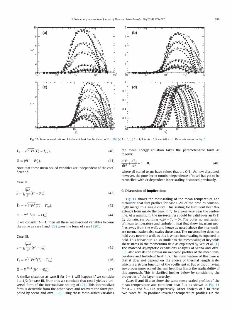
Fig. 10. Inner normalizations of turbulent heat flux for Case I of Eq. (20). (a) b ¼ 0, (b) b ¼ 1=3, (c) b ¼ 1=2 and (d) b ¼ 1. Data sets are as for Fig. 5.
S. Saha et al. / International Journal of Heat and Mass Transfer 70 (2014) 779–792 789
T/ ¼ffiffiffiffiffiffiffiffiffiffidþPr
pTþh � Tþhm
� �; ð40Þ
H ¼ Hþ �Hþm� �
: ð41Þ
Note that these meso-scaled variables are independent of the coef-ficient b.
Case II.
y ¼
ffiffiffiffiffiffiffiPrb
dþ
syþ � yþm� �
; ð42Þ
T/ ¼ffiffiffiffiffiffiffiffiffiffiffiffidþPrb
pTþh � Tþhm
� �; ð43Þ
H ¼ Prb�1 Hþ �Hþm� �
: ð44Þ
If we consider b ¼ 1, then all these meso-scaled variables becomethe same as case I and (23) takes the form of case I (20).
Case III.
y ¼
ffiffiffiffiffiffiffiffiffiPr2b
dþ
syþ � yþm� �
; ð45Þ
T/ ¼ffiffiffiffiffiffiffiffiffiffiffiffiffiffidþPr2b
pTþh � Tþhm
� �; ð46Þ
H ¼ Pr2b�1 Hþ �Hþm� �
: ð47Þ
A similar situation as case II for b ¼ 1 will happen if we considerb ¼ 1=2 for case III. From this we conclude that case I yields a uni-versal form of the intermediate scaling of (23). This intermediateform is derivable from the other cases and recovers the form pro-posed by Seena and Afzal [38]. Using these meso-scaled variables,
the mean energy equation takes the parameter-free form asfollows:
d2Hdy2 þ
dT/
dyþ 1 ¼ 0; ð48Þ
where all scaled terms have values that are Oð1Þ. As now discussed,however, the pure Peclet number dependence of case I has yet to bereconciled with Pr dependent inner scaling discussed previously.
9. Discussion of implications
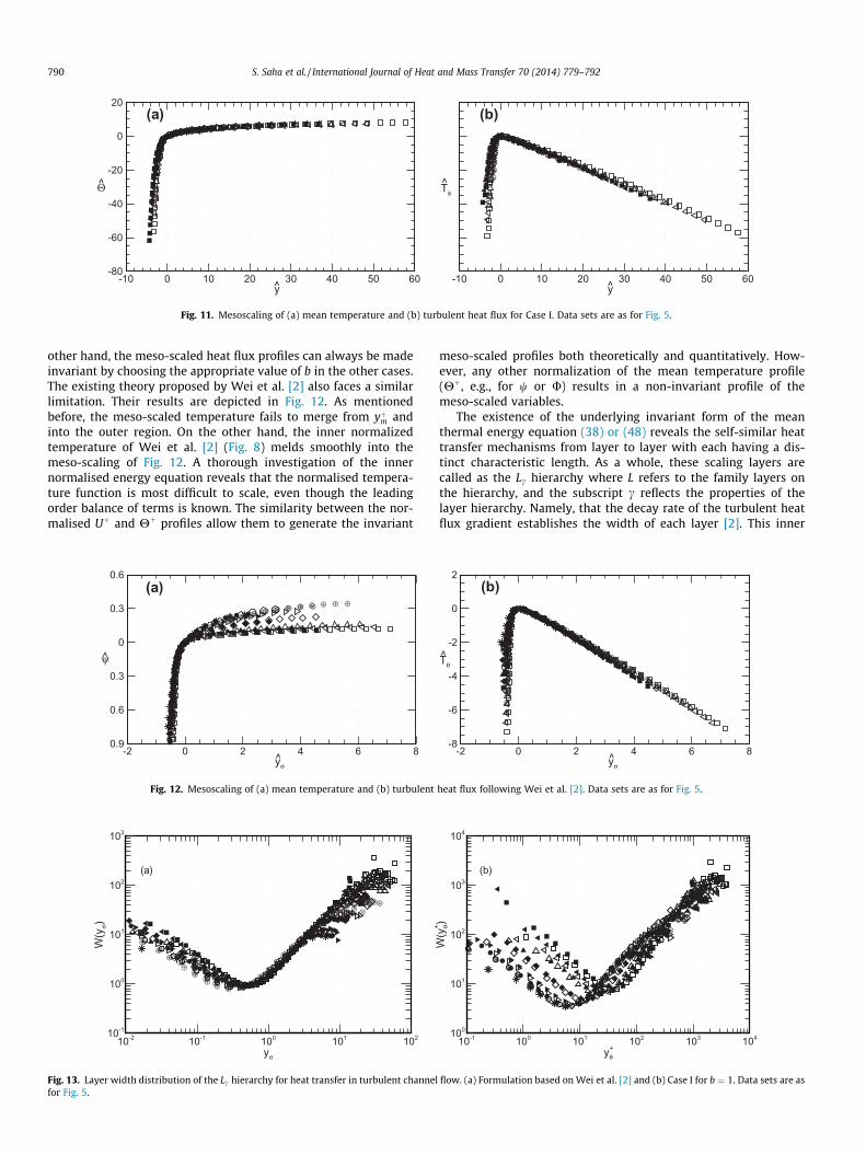
Fig. 11 shows the mesoscaling of the mean temperature andturbulent heat flux profiles for case I. All of the profiles convinc-ingly merge to a single curve. This scaling for turbulent heat fluxextends from inside the peak in Tþh to a zone very near the center-line. At a minimum, the mesoscaling should be valid over an Oð1ÞDy domain, surrounding yþmðy ¼ T/ ¼ 0Þ. The outer normalizationof mean temperature and turbulent heat flux show invariant pro-files away from the wall, and hence as noted above the intermedi-ate normalization also scales these data. The mesoscaling does nothold very near the wall, as this is where inner scaling is expected tohold. This behaviour is also similar to the mesoscaling of Reynoldsshear stress in the momentum field as explained by Wei et al. [1].The matched asymptotic expansions analysis of Seena and Afzal[38] also reveals the similar meso-scaled profiles of the mean tem-perature and turbulent heat flux. The main feature of this case isthat it does not depend on the choice of thermal length scale,which is a strong function of the coefficient b. But without havingany proper inner scaled thermal heat flux limits the applicability ofthis approach. This is clarified further below by considering theproperties of the layer hierarchy.
Cases II and III also show the same meso-scaled profiles of themean temperature and turbulent heat flux as shown in Fig. 11for b ¼ 1 and b ¼ 1=2 respectively. Other choices of b in thesetwo cases fail to produce invariant temperature profiles. On the
⊗⊗⊗
⊗ ⊗ ⊗ ⊗ ⊗ ⊗ ⊗
⊕⊕⊕
⊕ ⊕ ⊕ ⊕ ⊕ ⊕ ⊕ ⊕ ⊕
-10 0 10 20 30 40 50 60-80
-60
-40
-20
0
20(a)
y
Θ
⊗⊗⊗⊗⊗ ⊗ ⊗ ⊗ ⊗ ⊗ ⊗ ⊗ ⊗
⊕⊕⊕⊕⊕⊕ ⊕ ⊕ ⊕ ⊕ ⊕ ⊕ ⊕ ⊕ ⊕ ⊕ ⊕
-10 0 10 20 30 40 50 60
(b)
y
Tφ
Fig. 11. Mesoscaling of (a) mean temperature and (b) turbulent heat flux for Case I. Data sets are as for Fig. 5.
790 S. Saha et al. / International Journal of Heat and Mass Transfer 70 (2014) 779–792
other hand, the meso-scaled heat flux profiles can always be madeinvariant by choosing the appropriate value of b in the other cases.The existing theory proposed by Wei et al. [2] also faces a similarlimitation. Their results are depicted in Fig. 12. As mentionedbefore, the meso-scaled temperature fails to merge from yþm andinto the outer region. On the other hand, the inner normalizedtemperature of Wei et al. [2] (Fig. 8) melds smoothly into themeso-scaling of Fig. 12. A thorough investigation of the innernormalised energy equation reveals that the normalised tempera-ture function is most difficult to scale, even though the leadingorder balance of terms is known. The similarity between the nor-malised Uþ and Hþ profiles allow them to generate the invariant
⊗⊗⊗⊗⊗⊗⊗⊗⊗
⊗⊗ ⊗ ⊗ ⊗ ⊗ ⊗ ⊗ ⊗ ⊗ ⊗ ⊗ ⊗
⊕⊕⊕⊕⊕⊕⊕⊕⊕⊕
⊕⊕ ⊕ ⊕ ⊕ ⊕ ⊕ ⊕ ⊕ ⊕ ⊕ ⊕ ⊕ ⊕ ⊕
-2 0 2 4 6 80.9
0.6
0.3
0
0.3
0.6(a)
yσ
ψ
Fig. 12. Mesoscaling of (a) mean temperature and (b) turbulent
⊗⊗
⊗⊗
⊗⊗ ⊗ ⊗ ⊗
⊗⊗
⊗⊗
⊗⊗
⊗⊗
⊗⊗ ⊗
⊗ ⊗ ⊗
⊕⊕
⊕⊕
⊕⊕ ⊕ ⊕ ⊕ ⊕
⊕⊕
⊕⊕
⊕⊕
⊕⊕
⊕⊕
⊕ ⊕⊕⊕⊕⊕⊕⊕
yσ
W(y
σ)
10-2 10-1 100 101 10210-1
100
101
102
103
(a)
Fig. 13. Layer width distribution of the Lc hierarchy for heat transfer in turbulent channelfor Fig. 5.
meso-scaled profiles both theoretically and quantitatively. How-ever, any other normalization of the mean temperature profile(Hþ, e.g., for w or U) results in a non-invariant profile of themeso-scaled variables.
The existence of the underlying invariant form of the meanthermal energy equation (38) or (48) reveals the self-similar heattransfer mechanisms from layer to layer with each having a dis-tinct characteristic length. As a whole, these scaling layers arecalled as the Lc hierarchy where L refers to the family layers onthe hierarchy, and the subscript c reflects the properties of thelayer hierarchy. Namely, that the decay rate of the turbulent heatflux gradient establishes the width of each layer [2]. This inner
⊗⊗⊗⊗⊗⊗⊗⊗⊗ ⊗ ⊗ ⊗ ⊗ ⊗ ⊗
⊗⊗
⊗ ⊗⊗
⊗⊗
⊗⊗
⊕⊕⊕⊕⊕⊕⊕⊕⊕⊕⊕⊕⊕ ⊕ ⊕ ⊕ ⊕ ⊕ ⊕
⊕ ⊕⊕
⊕⊕
⊕⊕ ⊕ ⊕
⊕⊕
⊕
-2 0 2 4 6 8-8
-6
-4
-2
0
2(b)
yσ
Tθ
heat flux following Wei et al. [2]. Data sets are as for Fig. 5.
⊗⊗
⊗⊗
⊗⊗
⊗ ⊗ ⊗⊗
⊗⊗
⊗⊗
⊗⊗
⊗⊗
⊗ ⊗ ⊗
⊕⊕
⊕⊕
⊕⊕
⊕⊕ ⊕ ⊕
⊕⊕
⊕⊕
⊕⊕
⊕⊕
⊕⊕
⊕⊕⊕⊕⊕⊕⊕
yθ+
W(y
θ+ )
10-1 100 101 102 103 104100
101
102
103
104
(b)
flow. (a) Formulation based on Wei et al. [2] and (b) Case I for b ¼ 1. Data sets are as
S. Saha et al. / International Journal of Heat and Mass Transfer 70 (2014) 779–792 791
normalized length distribution, W, accounts for the width of eachLc as a function of yþh . The layers on this hierarchy have increasingwidth with distance from the wall, with the first layer starting nearthe wall and the last layer ending near the centerline. Using thetheory developed by Wei et al. [2], one can compute the layerwidth distribution, WðyrÞ, which effectively depends upon the de-cay rate of term B in (18) across the hierarchy. Namely,
W yrð Þ ¼ O c�1=2� �; ð49Þ
where the parameter c can be evaluated as
c ¼ dTþhdyrþ r2Rr yrð Þ: ð50Þ
The introduction of the new inner scale yr allows one to determinehow the scaling approach effectively satisfies the layer hierarchyrequirement with increasing Reynolds and Prandtl numbers. Themean momentum balance theory indicates that a linear WðyþÞ pro-file (exact or approximate) is required for the existence of a loga-rithmic mean velocity profile [49]. The same is applicable to themean thermal energy balance relative to the development of a log-arithmic mean temperature profile, and the evolution of the WðyrÞprofiles is shown in Fig. 13(a) for the existing channel flow DNSdata. The same theory also allows one to compute the layer widthdistributions, Wðyþh Þ under the normalization of case I and this isillustrated in Fig. 13(b). The remarkable finding here is that whileboth of the W distributions of Fig. 13 develop an approximately(emerging) linear W distribution, this W distribution is nearlyinvariant under the formulation of Wei et al. [2], but exhibits clearvariations for the case I formulation.
10. Conclusions
The scaling properties of mean thermal energy balance equa-tion for turbulent heat transfer in a channel have been investigatedwith the aid of existing DNS data. A generalized framework wasemployed. This allowed the relative influences of Re and Pr onthe construction of invariant forms of the equation to be explored.Only one meso-normalization was found that accurately scaledboth mean temperature and turbulent heat flux irrespective ofthe variations in Reynolds and Prandtl numbers. The derived mes-oscaling (pure Pe) applied to both the turbulent heat flux and themean temperature serves to merge the various data profiles to asingle curve over a range of distances from the wall that extendsfrom interior to the peak heat flux to the channel center line. Thisscaling characteristics exhibits similarity to the Reynolds stress athigh Reynolds number. Unlike the momentum analysis, the pro-posed scaling approach fails to display the correct profile of thelayer hierarchy associated with the intermediate normalization.The framework underlying the pure Peclet number scaling failsto yield viable inner scaling. Physically this may be because thisframework does not automatically embrace the differential ratesof heat and momentum transport in the region where the molecu-lar diffusion is dominant.
Acknowledgements
The authors gratefully acknowledge the financial support of theAustralian Research Council and the computational resources pro-vided by a Victorian Life Sciences Computation Initiative (VLSCI)grant on its Peak Computing Facility at the University of Mel-bourne, an initiative of the Victorian Government. We wish tothank Dr. H. Abe for providing us turbulent heat transfer data(Res ¼ 1020, Pr ¼ 0:025).
References
[1] T. Wei, P. Fife, J. Klewicki, P. McMurtry, Properties of the mean momentumbalance in turbulent boundary layer, pipe and channel flows, J. Fluid Mech. 522(2005) 303–327.
[2] T. Wei, P. Fife, J. Klewicki, P. McMurtry, Scaling Heat Transfer in FullyDeveloped Turbulent Channel Flow, Int. J. Heat Mass Transfer 48 (2005) 5284–5296.
[3] R. Gowen, J. Smith, The effect of the Prandtl number on temperatureprofiles for heat transfer in turbulent pipe flow, Chem. Eng. Sci. 22 (1967)1701–1711.
[4] B. Kader, Temperature and concentration profiles in fully turbulent boundarylayers, Int. J. Heat Mass Transfer 24 (1981) 1541–1544.
[5] X. Wang, L. Castillo, G. Araya, Temperature Scalings and Profiles in ForcedConvection Turbulent Boundary Layers, Journal of Heat Transfer 130 (2)021701.
[6] M. Dhotre, J. Joshi, CFD Simulation of Heat Transfer in Turbulent Pipe Flow, Ind.Eng. Chem. Res. 43 (2004) 2816–2829.
[7] H. Kawamura, H. Abe, Y. Matsuo, DNS of Turbulent Heat Transfer in ChannelFlow with Respect to Reynolds and Prandtl Number Effects, Int. J. Heat FluidFlow 20 (1999) 196–207.
[8] S. Satake, T. Kunugi, R. Himeno, High Reynolds number computation forturbulent Heat Transfer in a pipe flow, in: High Performance Computing, ThirdInternational Symposium, Tokyo, Japan, 514–523, 2000.
[9] L. Redjem-Saad, M. Ould-Rouiss, G. Lauriat, Direct numerical simulation ofturbulent heat transfer in pipe flows: Effect of Prandtl number, Int. J. Heat FluidFlow 28 (5) (2007) 847–861.
[10] H. Abe, H. Kawamura, Y. Matsuo, DNS of Turbulent Heat Transfer in ChannelFlow: Near-wall Turbulence Quantities, in: 13th Australasian Fluid MechanicsConference, Melbourne, Australia, 849–852, 1998.
[11] H. Abe, H. Kawamura, Y. Matsuo, Surface heat-flux fluctuations in a turbulentchannel flow up to Res = 1020 with Pr = 0.025 and 0.71, Int. J. Heat Fluid Flow25 (3) (2004) 404–419.
[12] N. Kasagi, Y. Ohtsubo, Direct Numerical Simulation of Low Prandtl NumberThermal Field in a Turbulent Channel Flow, vol. 8, Springer, Berlin, 1993, pp.97–119.
[13] N. Kasagi, T. Tomita, K. Kuroda, Direct numerical simulation of passive scalarfield in a turbulent channel flow, Trans. ASME J. Heat Transfer 114 (1992)598606.
[14] H. Kawamura, H. Abe, DNS of turbulent scalar transport in a channel flow up toRes ¼ 640 with Pr ¼ 0:025 and 0.71, in: Seventh TRA Conference, Seoul Nat’lUniv., Seoul, Korea, 2002, pp. 65–79.
[15] H. Kawamura, H. Abe, Y. Matsuo, Very large-scale structures observed in DNSof turbulent channel flow with passive scalar transport, in: 15th AustralasianFluid Mechanics Conference, Sydney, Australia, 2004.
[16] H. Kawamura, H. Abe, K. Shingai, DNS of turbulence and heat transport in achannel flow with different Reynolds and Prandtl numbers and boundaryconditions, in: Y. Nagano, K. Hanjalic, T. Tsuji (Eds.), Third InternationalSymposium on Turbulence, Heat and Mass Transfer, 2000, pp. 15–32.
[17] H. Kawamura, K. Ohsaka, H. Abe, K. Yamamoto, DNS of turbulent heat transferin channel flow with low to medium-high Prandtl number fluid, Int. J. HeatFluid Flow 19 (5) (1998) 482–491.
[18] H. Kawamura, K. Ohsaka, K. Yamamoto, DNS of turbulent heat transfer inchannel flow with low to medium-high Prandtl number Fluid, in: 11thSymposium Turbulent Shear Flows, vol. 1, Grenoble, 1997, pp. 8.7–8.12.
[19] J. Kim, P. Moin, Transport of Passive Scalars in a Turbulent Channel Flow, vol.VI, Springer-Verlag, 1989, pp. 85–96.
[20] M. Kozuka, Y. Seki, H. Kawamura, DNS of turbulent heat transfer in a channelflow with a high spatial resolution, Int. J. Heat Fluid Flow 30 (3) (2009) 514–524.
[21] M. Piller, E. Nobile, T.J. Hanratty, DNS study of turbulent transport at lowPrandtl numbers in a channel flow, J. Fluid Mech. 458 (2002) 419–441.
[22] S. Saha, C. Chin, H. Blackbun, A. Ooi, The influence of pipe length on thermalstatistics computed from DNS of turbuelnt heat transfer, Int. J. Heat Fluid Flow32 (2011) 1083–1097.
[23] Y. Seki, K. Iwamoto, H. Kawamura, Prandtl number effect on turbulencequantities through high spatial resolution DNS of turbulent heat transfer in achannel flow, in: chap. Fifth International Symposium on Turbulence, Heat andMass Transfer, Dubrovnik, Croatia, 2006, pp. 301–304.
[24] T. Tsukahara, Y. Seki, H. Kawamura, D. Tochio, DNS of turbulent heat transfer ina channel flow at very low Reynolds numbers, in: 1st International Forum onHeat Transfer, Kyoto, Japan, 2004, pp. 195–196.
[25] Y. Yamamoto, T. Kunugi, Y. Tsuji, Effects of very-large scale structures in ahigh-Reynolds turbulent channel flow on medium-high Prandtl number heattransfer (2009) 1–7.
[26] W.K. George, L. Castillo, Zero-pressure-gradient turbulent boundary layer,Appl. Mech. Rev. 50 (12) (1997) 689–729.
[27] S.W. Churchill, C. Chan, Turbulent flow in channels in terms of turbulent shearand normal stresses, AIChE J. 41 (12) (1995) 2513–2521.
[28] S.W. Churchill, B. Yu, Y. Kawaguchi, The accuracy and parametric sensitivity ofalgebraic models for turbulent flow and convection, Int. J. Heat Mass Transfer48 (25-26) (2005) 5488–5503.
[29] P.M. Le, D.V. Papavassiliou, On temperature prediction at low Re turbulentflows using the Churchill turbulent heat flux correlation, Int. J. Heat MassTransfer 49 (19-20) (2006) 3681–3690.
792 S. Saha et al. / International Journal of Heat and Mass Transfer 70 (2014) 779–792
[30] N. Marati, J. Davoudi, C.M. Casciola, B. Eckhardt, Mean profiles for a passivescalar in wall-bounded flows from symmetry analysis, J. Turbulence 7 (2006)61.
[31] N. Afzal, Fully developed turbulent flow in a pipe: An intermediate layer, Arch.Appl. Mech. (Ingenieur-Archiv) 52 (1982) 355–377.
[32] A. Seena, N. Afzal, Power law velocity and temperature profiles in a fullydeveloped turbulent channel flow, J. Heat Transfer 130 (2008) 091701.
[33] A. Isakson, On the formula for the velocity distribution near walls, Tech. Phys.USSR. IV (1937) 155–159.
[34] A. Kolmogorov, The local structure of turbulence in incompressible viscousfluid for very large Reynolds numbers, in: Proceedings of the Royal Society,London, Ser. A, vol. 434 (1890), 1991, pp. 9–13.
[35] C. Millikan, A critical discussion of turbulent flow in channels and circulartubes, in: J. den Hartog, H. Peters (Eds.), 5th International Congress for AppliedMechanics, Wiley/Chapman and Hall, New York, London, 1938, pp. 386–392.
[36] N. Afzal, A. Seena, A. Bushra, Power law turbulent velocity profile intransitional rough pipes, J. Fluids Eng. 128 (3) (2006) 548–558.
[37] N. Afzal, A. Seena, A. Bushra, Power law velocity profile in fully developedturbulent pipe and channel flows, J. Hydraul. Eng. 133 (9) (2007) 1080–1086.
[38] A. Seena, N. Afzal, Intermediate scaling of turbulent momentum and heattransfer in a transitional rough channel, J. Heat Transfer 130 (2008) 031701.
[39] A. Seena, A. Bushra, N. Afzal, Logarithmic expansions for Reynolds shear stressand reynolds heat flux in a turbulent channel flow, ASME J. Heat Transfer 130(2008) 094501.
[40] J.P. Monty, N. Hutchins, H.C.H. Ng, I. Marusic, M.S. Chong, A comparison ofturbulent pipe, channel and boundary layer flows, J. Fluid Mech. 632 (2009)431–442.
[41] J.P. Monty, J.A. Stewart, R.C. Williams, M.S. Chong, Large-scale features inturbulent pipe and channel flows, J. Fluid Mech. 589 (2007) 147–156.
[42] H. Ng, J. Monty, N. Hutchins, M. Chong, I. Marusic, Comparison of turbulentchannel and pipe flows with varying Reynolds number, Exp. Fluids 51 (2011)1261–1281.
[43] T. Wei, P. McMurtry, J. Klewicki, P. Fife, Mesoscaling of Reynolds shear stress inturbulent channel and pipe flows, AIAA J. 43 (11) (2005) 2350–2353.
[44] T. Wei, P. Fife, J. Klewicki, On scaling the mean momentum balance and itssolutions in turbulent Couette–Poiseuille flow, J. Fluid Mech. 573 (2007) 371–398.
[45] J. Elsnab, J. Klewicki, D. Maynes, T. Ameel, Mean dynamics of transitionalchannel flow, J. Fluid Mech. 678 (2011) 451–481.
[46] P. Fife, J. Klewicki, P. McMurtry, T. Wei, Multiscaling in the presence ofindeterminacy: wall-induced turbulence, Multiscale Model. Simul. 4 (3)(2005) 936–959.
[47] P. Fife, T. Wei, J. Klewicki, P. McMurtry, Stress gradient balance layers and scalehierarchies in wall-bounded turbulent flows, J. Fluid Mech. 532 (2005) 165–189.
[48] J. Klewicki, C. Chin, H. Blackburn, A. Ooi, I. Marusic, Emergence of the four layerdynamical regime in turbulent pipe flow, Phys. Fluids 24 (2012) 045107.
[49] J. Klewicki, P. Fife, T. Wei, On the logarithmic mean profile, J. Fluid Mech. 638(2009) 73–93.
[50] Y. Seki, H. Kawamura, DNS of turbulent heat transfer in a channel flow with avarying streamwisely thermal boundary condition, Heat Transfer – Asian Res.35 (4) (2006) 265–278.
[51] S.B. Pope, Turbulent Flows, Cambridge University Press, Cambridge, UK, 2000.[52] H. Tennekes, J.L. Lumley, A First Course in Turbulence, MIT Press, Cambridge,
MA, 1972.[53] A.A. Townsend, The Structure of Turbulent Shear Flow, Cambridge University
Press, Cambridge, UK, 1980.[54] M. Wosnik, L. Castillo, W.K. George, A theory for turbulent pipe and channel
flows, J. Fluid Mech. 421 (2000) 115–145.[55] P. Fife, J. Klewicki, T. Wei, Time averaging in turbulence settings may reveal an
infinite hierarchy of length scales, J. Discr. Contin. Dyn. Syst. 24 (3) (2009)781–807.
[56] L. Castillo, W.K. George, Similarity analysis for turbulent boundary layer withpressure gradient: outer flow, AIAA J. 39 (1) (2001) 41–47.
[57] X. Wang, L. Castillo, Asymptotic solutions in forced convection turbulentboundary layers, J. Turbulence 4 (2003) N6.
[58] N. Afzal, Mesolayer theory for turbulent flows, AIAA J. 22 (3) (1984) 437–439.[59] J. Klewicki, R. Ebner, X. Wu, Mean dynamics of transitional boundary-layer
flow, J. Fluid Mech. 682 (2011) 617–651.


![AGREEMENT FOR SALE202.61.117.163/attachments/GridAttach/hira/nproj/10455000000000/axp...arshad iqbal momen[income tax PAN: AFCPM7676P ], son of Golam Momen, residing at 6 Rawdon Street](https://img.pdfslide.us/doc/110x75/5dd0fc4bd6be591ccb63a984/agreement-for-sale20261117163attachmentsgridattachhiranproj10455000000000axparshad.jpg)