Embed Size (px)
Citation preview
1 PCI-2-5, 2018
Copyright ©2018 by Rolf D. Reitz. This material is not to be sold, reproduced or distributed without prior written permission of the owner, Rolf D. Reitz.
Internal Combustion Engines I: Fundamentals and Performance Metrics
Prof. Rolf D. Reitz,
Engine Research Center, University of Wisconsin-Madison
2018 Princeton-Combustion Institute Summer School on Combustion
Course Length: 9 hrs (Mon.- Wed., June 25-27)
Hour 5: Premixed Charge Spark-ignited engines
Hour 5: Premixed Charge Spark-ignited engines
2 PCI-2-5, 2018
Short course outline:
Internal Combustion (IC) engine fundamentals and performance metrics, computer modeling supported by in-depth understanding of fundamental engine processes and detailed experiments in engine design optimization.
Day 1 (Engine fundamentals)
Hour 1: IC Engine Review, Thermodynamics and 0-D modeling Hour 2: 1-D modeling, Charge Preparation Hour 3: Engine Performance Metrics, 3-D flow modeling
Day 2 (Computer modeling/engine processes)
Hour 4: Engine combustion physics and chemistry Hour 5: Premixed Charge Spark-ignited engines Hour 6: Spray modeling
Day 3 (Engine Applications and Optimization) Hour 7: Heat transfer and Spray Combustion Research Hour 8: Diesel Combustion modeling Hour 9: Optimization and Low Temperature Combustion
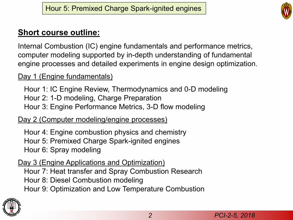
Spark Ignition Engine
Turbulent Flame Propagation • G-equation description of combustion • Laminar and turbulent flame speeds • Primary heat release calculation • Flame quench due to mixture stratification Post-flame Chemistry • CO oxidation, H2-O2 reactions • Pollutant formation mechanisms
Knocking Combustion • Auto-ignition mechanisms • Location / intensity
SI engine combustion modeling
Flame propagation Models with Detailed Chemistry
Liang, 2006
3 PCI-2-5, 2018
Spark plug
Hour 5: Premixed Charge Spark-ignited engines
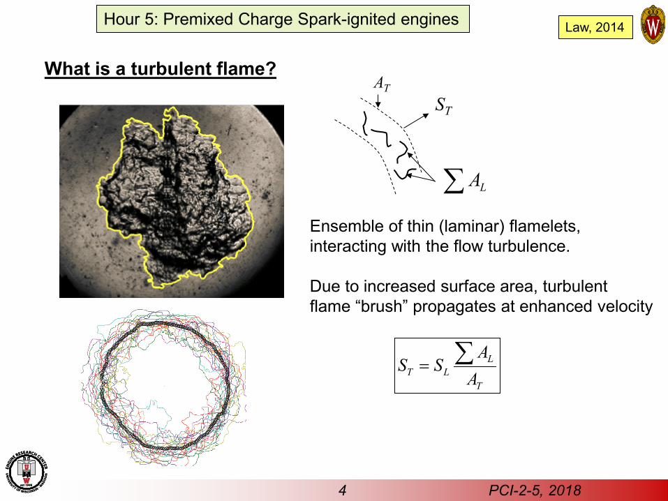
What is a turbulent flame?
Law, 2014
ST
Ensemble of thin (laminar) flamelets, interacting with the flow turbulence. Due to increased surface area, turbulent flame “brush” propagates at enhanced velocity
LT L
T
AS S
A= ∑
AT
LA∑
4 PCI-2-5, 2018
Hour 5: Premixed Charge Spark-ignited engines
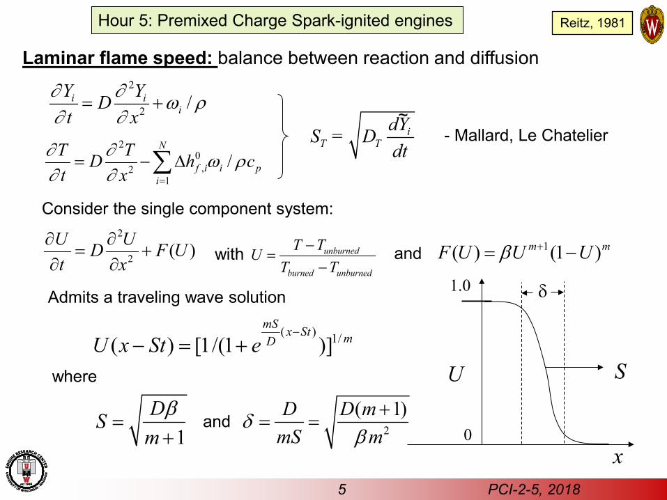
Laminar flame speed: balance between reaction and diffusion
iT T
dYS = Ddt
5 PCI-2-5, 2018
2
2 /i ii
Y YDt x
∂ ∂ ω ρ∂ ∂
= +
20
,21
/N
f i i pi
T TD h ct x
∂ ∂ ω ρ∂ ∂ =
= − ∆∑
( ) 1/( ) [1/(1 )]mS x St mDU x St e
−− = +
2
2 ( )U UD F Ut x
∂ ∂= +
∂ ∂1( ) (1 )m mF U U Uβ += −
1DS
mβ
=+
Consider the single component system:
unburned
burned unburned
T TUT T
−=
−with and
Admits a traveling wave solution
where
2
( 1)D D mmS m
δβ
+= =and
U
x
S
1.0
0
δ
- Mallard, Le Chatelier ~
Hour 5: Premixed Charge Spark-ignited engines Reitz, 1981
Quenched broken reaction zones
Kl lδ=
K Fl l=
Combustion regime diagram
Flamelets
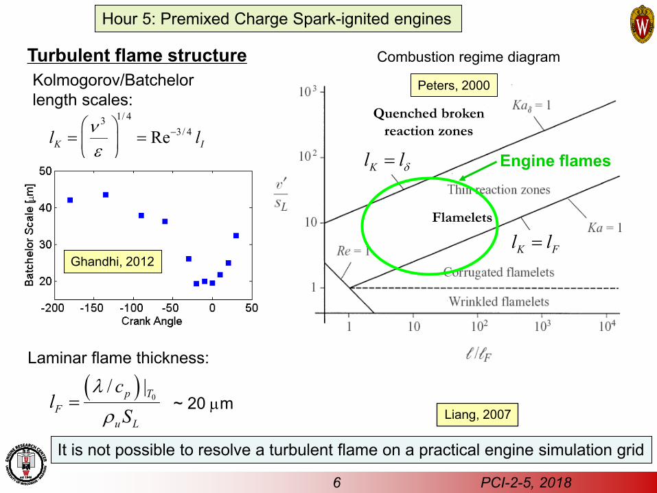
Turbulent flame structure
1/ 433/ 4ReK Il lν
ε−
= =
( ) 0/ |p T
Fu L
cl
Sλ
ρ=
Kolmogorov/Batchelor length scales:
Laminar flame thickness:
Ghandhi, 2012
~ 20 µm
It is not possible to resolve a turbulent flame on a practical engine simulation grid
Peters, 2000
Liang, 2007
6 PCI-2-5, 2018
Engine flames
Hour 5: Premixed Charge Spark-ignited engines
GkDGSGvvtG
TTu
vertexf~~~~)(
~0 ∇−∇=∇⋅−+
∂∂
ρρ
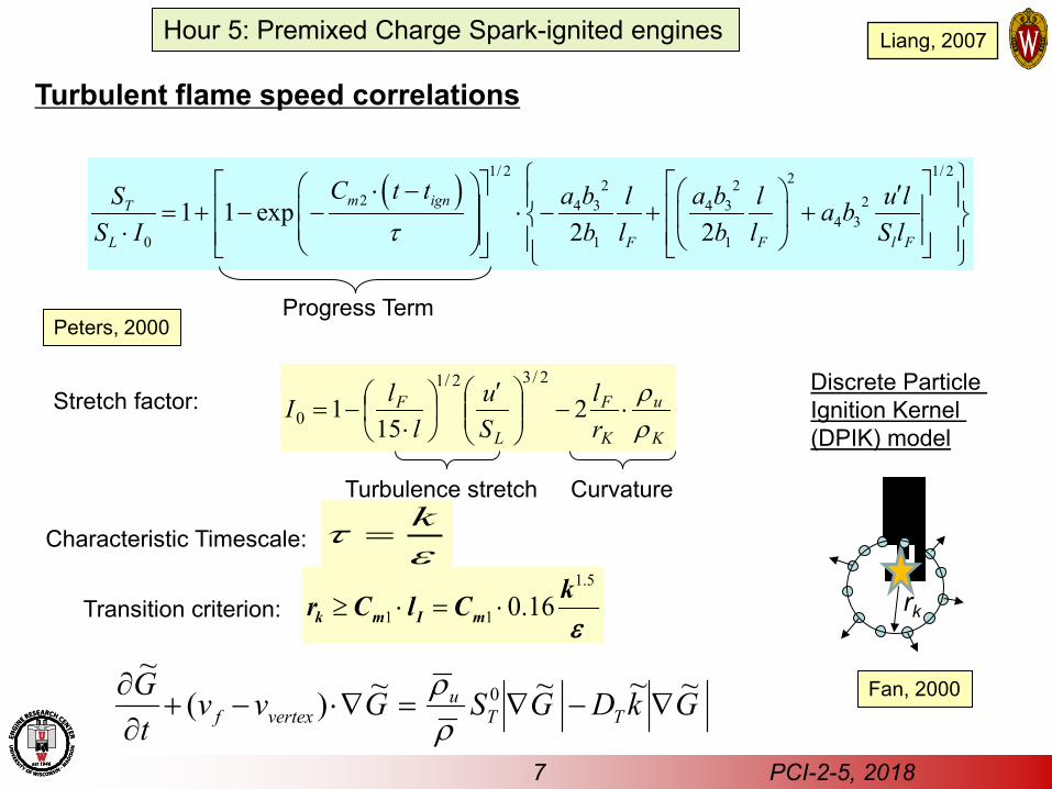
Turbulent flame speed correlations
( )1/ 2 1/ 222 2
2 24 3 4 34 3
0 1 1
1 1 exp2 2
m ignT
L F F l F
C t t a b a bS l l u la bS I b l b l S lτ
⋅ − ′ = + − − ⋅ − + + ⋅
Progress Term
1.5
1 1 0.16≥ ⋅ = ⋅k m I mkr C l Cε
ετ k
=
K
u
K
F
L
F
rl
Su
llI
ρρ
⋅−
′
⋅−= 2
151
2/32/1
0
Transition criterion:
Characteristic Timescale:
Stretch factor:
Turbulence stretch Curvature
Discrete Particle Ignition Kernel (DPIK) model
rk
Fan, 2000
Peters, 2000
7 PCI-2-5, 2018
Hour 5: Premixed Charge Spark-ignited engines Liang, 2007
8 PCI-2-5, 2018
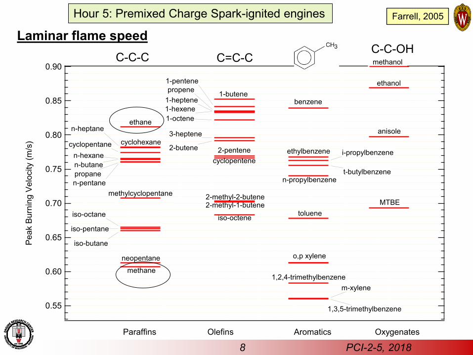
Laminar flame speed
0.90
0.85
0.80
0.75
0.70
0.65
0.60
0.55
Peak
Bur
ning
Vel
ocity
(m/s
)
Paraffins Olefins Aromatics
toluene
o,p xylene
Oxygenates
cyclohexane
benzene
anisole
ethanol
MTBEmethylcyclopentane
1,2,4-trimethylbenzene
iso-octene
n-butane propane
ethane
methane
n-pentane
iso-octane
iso-pentane
iso-butane
n-hexane
t-butylbenzene
i-propylbenzene
m-xylene
ethylbenzene
n-propylbenzene
1-butene
2-pentene
1-hexene
2-butene
3-heptene
cyclopentene
2-methyl-2-butene2-methyl-1-butene
propene
1,3,5-trimethylbenzene
1-pentene
cyclopentane
n-heptane
1-heptene
1-octene
neopentane
C-C-C C=C-C C-C-OH methanol
Hour 5: Premixed Charge Spark-ignited engines Farrell, 2005
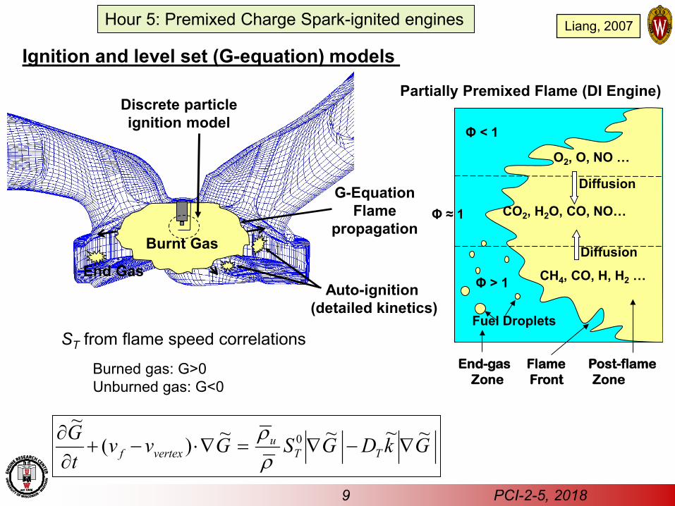
End Gas Auto-ignition
(detailed kinetics)
G-Equation Flame
propagation Burnt Gas
Discrete particle ignition model
ST from flame speed correlations
GkDGSGvvtG
TTu
vertexf~~~~)(
~0 ∇−∇=∇⋅−+
∂∂
ρρ
Ignition and level set (G-equation) models
Burned gas: G>0 Unburned gas: G<0
Liang, 2007
9 PCI-2-5, 2018
Hour 5: Premixed Charge Spark-ignited engines
Partially Premixed Flame (DI Engine)
Φ ≈ 1
Φ > 1
Φ < 1
CO2, H2O, CO, NO…
O2, O, NO …
Fuel Droplets
Diffusion
Diffusion
End-gas Flame Post-flame Zone Front Zone
CH4, CO, H, H2 …
10 PCI-2-5, 2018
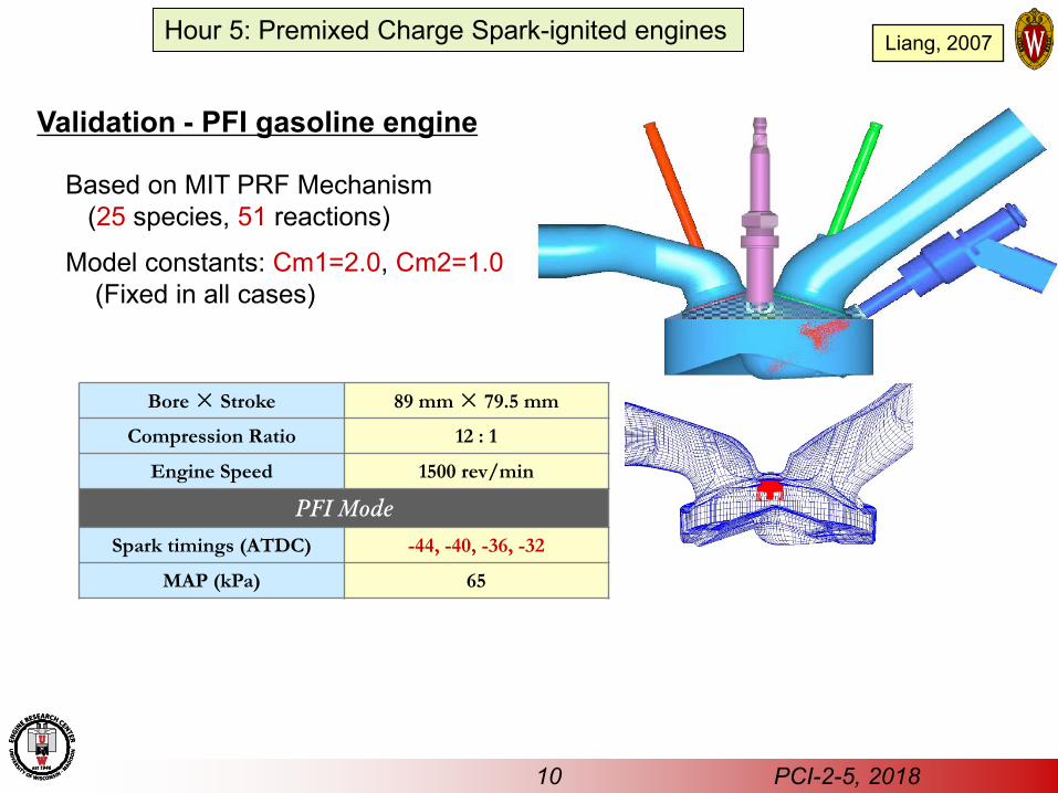
Validation - PFI gasoline engine
Bore × Stroke 89 mm × 79.5 mm
Compression Ratio 12 : 1
Engine Speed 1500 rev/min
PFI Mode Spark timings (ATDC) -44, -40, -36, -32
MAP (kPa) 65
Based on MIT PRF Mechanism (25 species, 51 reactions)
Model constants: Cm1=2.0, Cm2=1.0 (Fixed in all cases)
Hour 5: Premixed Charge Spark-ignited engines Liang, 2007
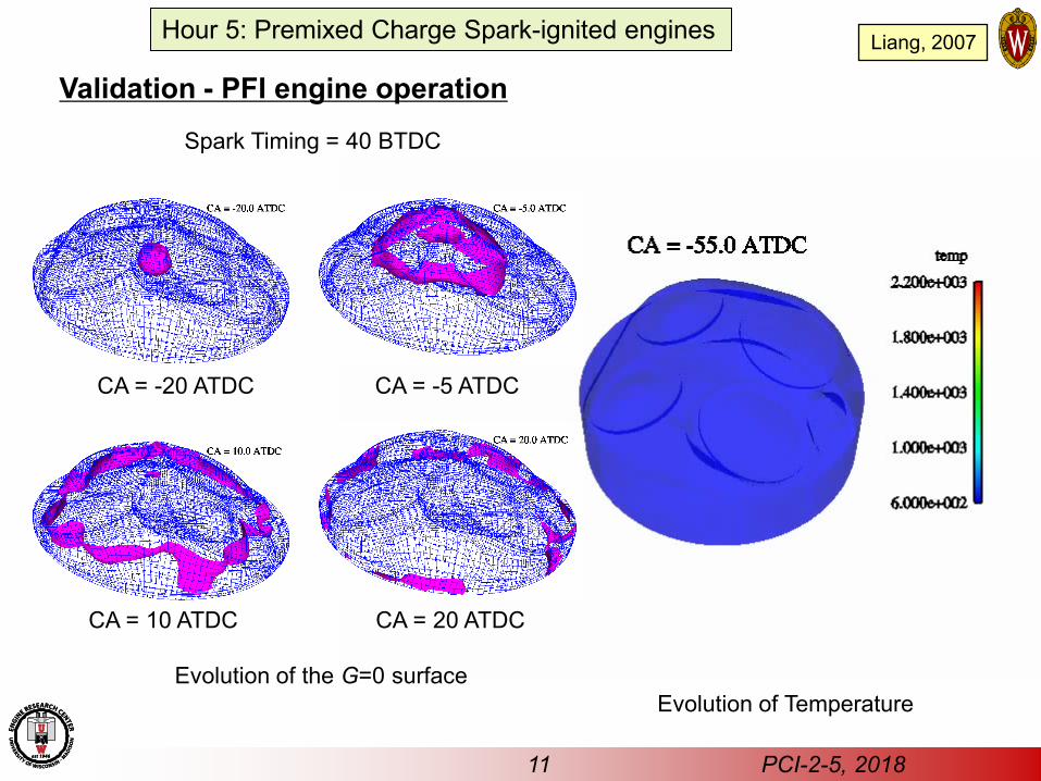
Validation - PFI engine operation
Evolution of Temperature
11 PCI-2-5, 2018
Hour 5: Premixed Charge Spark-ignited engines Liang, 2007
Spark Timing = 40 BTDC
Evolution of the G=0 surface
CA = -20 ATDC CA = -5 ATDC
CA = 10 ATDC CA = 20 ATDC
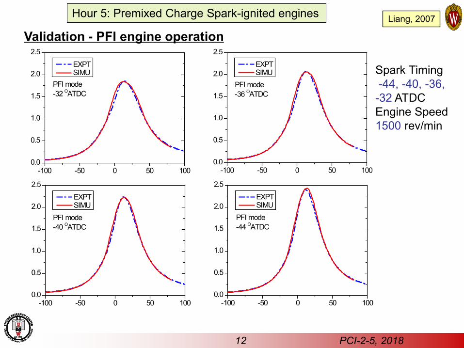
Validation - PFI engine operation
Spark Timing -44, -40, -36, -32 ATDC Engine Speed 1500 rev/min
-100 -50 0 50 1000.0
0.5
1.0
1.5
2.0
2.5
PFI mode-32 OATDC
EXPT SIMU
-100 -50 0 50 1000.0
0.5
1.0
1.5
2.0
2.5
PFI mode-36 OATDC
EXPT SIMU
-100 -50 0 50 1000.0
0.5
1.0
1.5
2.0
2.5
PFI mode-40 OATDC
EXPT SIMU
-100 -50 0 50 1000.0
0.5
1.0
1.5
2.0
2.5
EXPT SIMU
PFI mode-44 OATDC
12 PCI-2-5, 2018
Hour 5: Premixed Charge Spark-ignited engines Liang, 2007
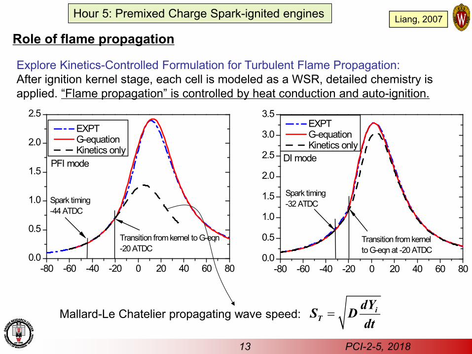
Role of flame propagation
Explore Kinetics-Controlled Formulation for Turbulent Flame Propagation: After ignition kernel stage, each cell is modeled as a WSR, detailed chemistry is applied. “Flame propagation” is controlled by heat conduction and auto-ignition.
-80 -60 -40 -20 0 20 40 60 800.0
0.5
1.0
1.5
2.0
2.5
Transition from kernel to G-eqn-20 ATDC
EXPT G-equation Kinetics only
Spark timing-44 ATDC
PFI mode
-80 -60 -40 -20 0 20 40 60 800.0
0.5
1.0
1.5
2.0
2.5
3.0
3.5
Transition from kernel to G-eqn at -20 ATDC
DI mode
Spark timing-32 ATDC
EXPT G-equation Kinetics only
Mallard-Le Chatelier propagating wave speed: = iT
dYS Ddt
13 PCI-2-5, 2018
Hour 5: Premixed Charge Spark-ignited engines Liang, 2007
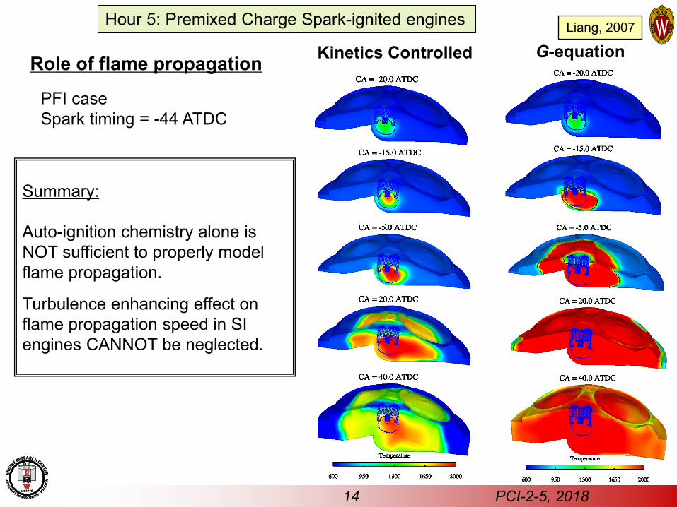
Kinetics Controlled G-equation
Summary: Auto-ignition chemistry alone is NOT sufficient to properly model flame propagation.
Turbulence enhancing effect on flame propagation speed in SI engines CANNOT be neglected.
PFI case Spark timing = -44 ATDC
Role of flame propagation
14 PCI-2-5, 2018
Hour 5: Premixed Charge Spark-ignited engines Liang, 2007
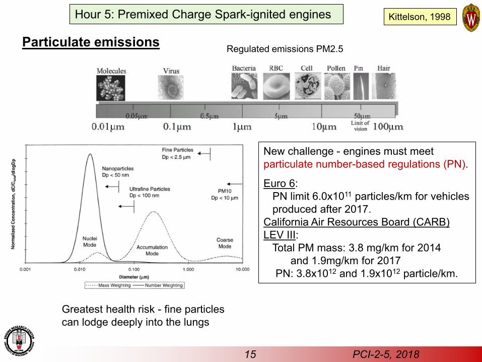
Particulate emissions
15 PCI-2-5, 2018
Regulated emissions PM2.5
Greatest health risk - fine particles can lodge deeply into the lungs
New challenge - engines must meet particulate number-based regulations (PN).
Euro 6: PN limit 6.0x10¹¹ particles/km for vehicles produced after 2017. California Air Resources Board (CARB) LEV III: Total PM mass: 3.8 mg/km for 2014 and 1.9mg/km for 2017 PN: 3.8x10¹² and 1.9x10¹² particle/km.
Kittelson, 1998 Hour 5: Premixed Charge Spark-ignited engines
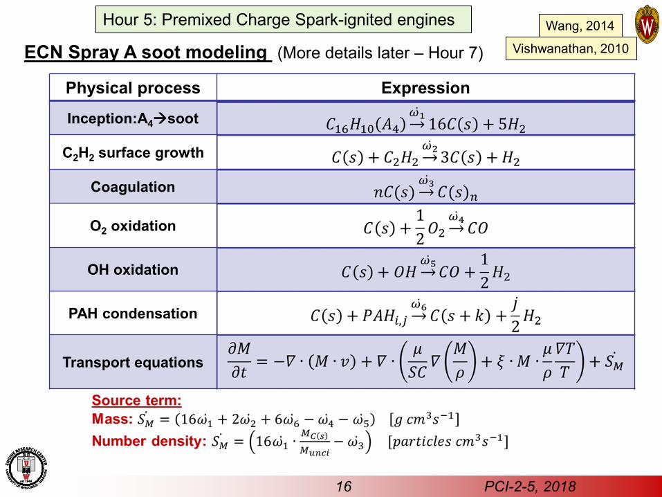
ECN Spray A soot modeling (More details later – Hour 7)
16 PCI-2-5, 2018
Physical process Expression
Inception:A4soot
C2H2 surface growth
Coagulation
O2 oxidation
OH oxidation
PAH condensation
Transport equations
Wang, 2014
Vishwanathan, 2010
Hour 5: Premixed Charge Spark-ignited engines
17 PCI-2-5, 2018
Jiao, 2014
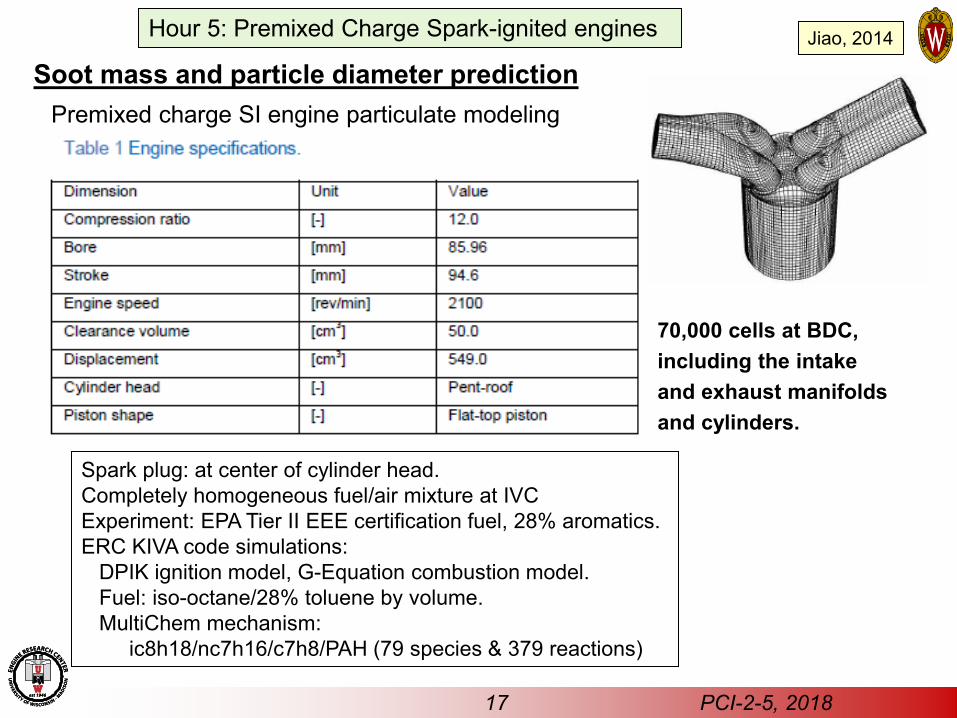
70,000 cells at BDC, including the intake and exhaust manifolds and cylinders.
Spark plug: at center of cylinder head. Completely homogeneous fuel/air mixture at IVC Experiment: EPA Tier II EEE certification fuel, 28% aromatics. ERC KIVA code simulations: DPIK ignition model, G-Equation combustion model. Fuel: iso-octane/28% toluene by volume. MultiChem mechanism: ic8h18/nc7h16/c7h8/PAH (79 species & 379 reactions)
Soot mass and particle diameter prediction Premixed charge SI engine particulate modeling
Hour 5: Premixed Charge Spark-ignited engines
•18
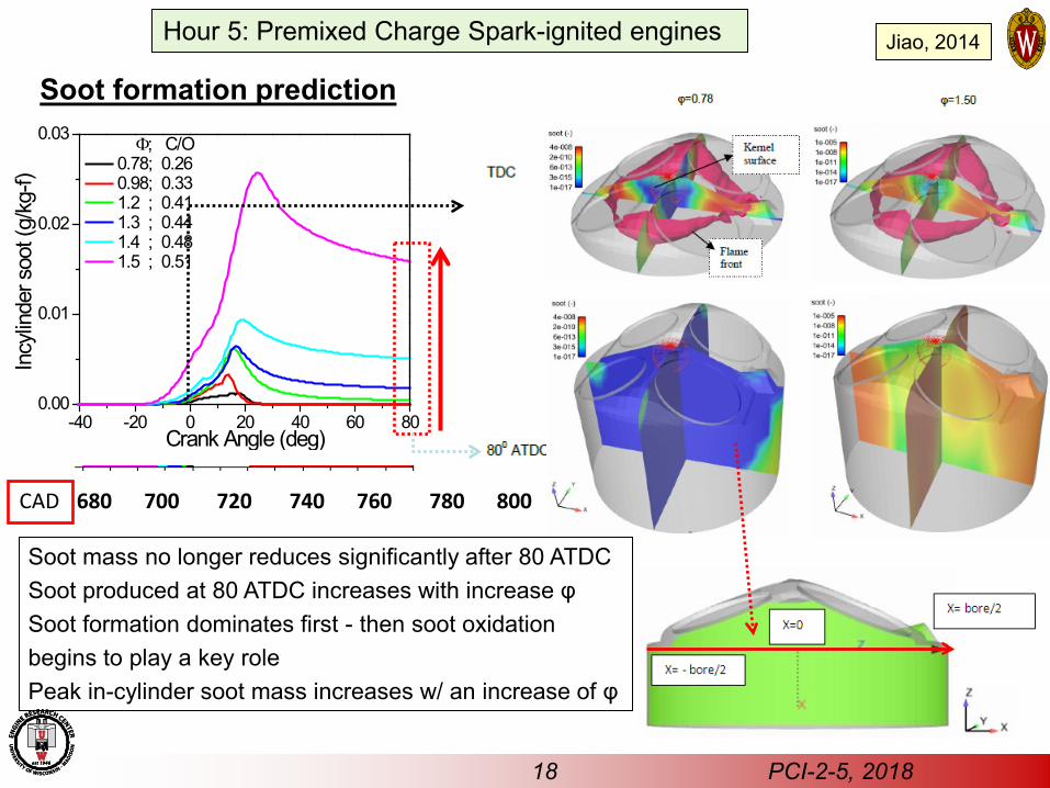
Soot formation prediction
-40 -20 0 20 40 60 800.00
0.01
0.02
0.03
0.78; 0.26 0.98; 0.33 1.2 ; 0.41 1.3 ; 0.44 1.4 ; 0.48 1.5 ; 0.51
Incy
linde
r soo
t (g/
kg-f)
Crank Angle (deg)
Φ; C/O
680 700 720 740 760 780 800 CAD
Soot mass no longer reduces significantly after 80 ATDC Soot produced at 80 ATDC increases with increase φ Soot formation dominates first - then soot oxidation begins to play a key role Peak in-cylinder soot mass increases w/ an increase of φ
18 PCI-2-5, 2018
Jiao, 2014 Hour 5: Premixed Charge Spark-ignited engines
-4 -3 -2 -1 0 1 2 3 4500
100015002000250030003500
Incylinder temperatureG
(-)
Te
mpe
ratu
re (K
)
Radial position (cm)
TDC
-2-101234
G (-)
-4 -3 -2 -1 0 1 2 3 40
5x10⁻¹⁰
1x10⁻⁹
2x10⁻⁹
2x10⁻⁹
C2 H
2 mass fraction (-)
A4 m
ass
fract
ion
(-)
Radial position (cm)
A4 mass fractionTDC
01x10-42x10-43x10-44x10-45x10-46x10-4
C2H2 mass fraction
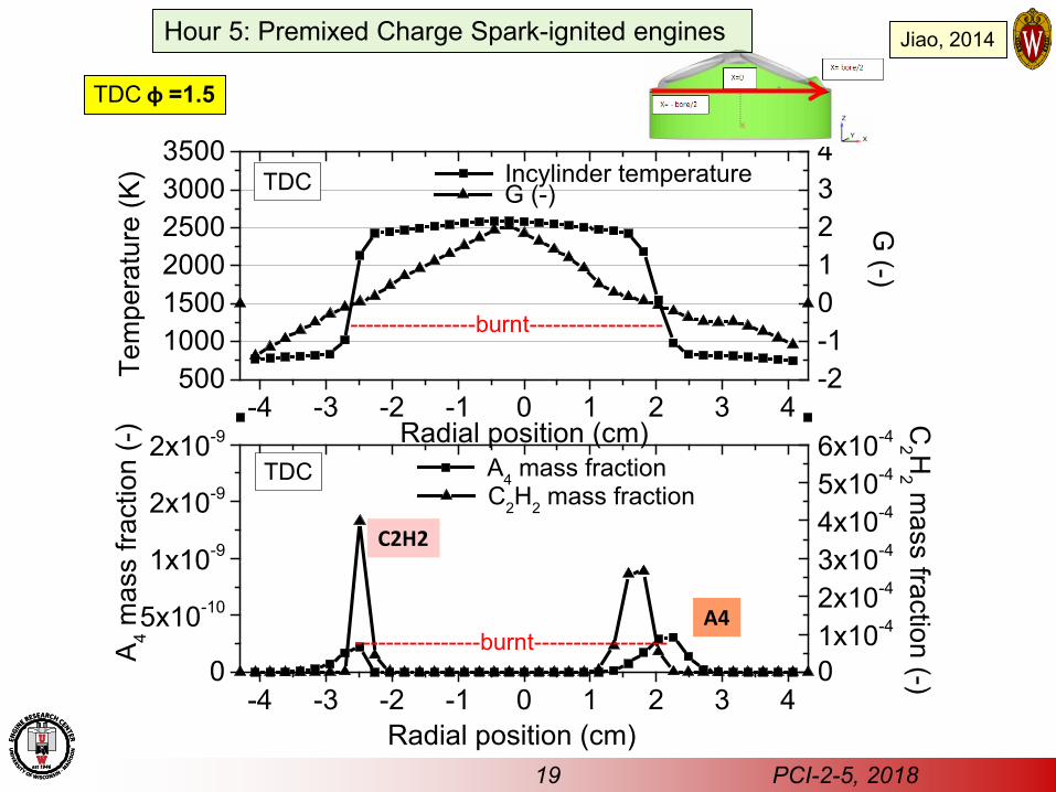
TDC φ =1.5
C2H2
A4
----------------burnt-----------------
----------------burnt-----------------
19 PCI-2-5, 2018
Jiao, 2014 Hour 5: Premixed Charge Spark-ignited engines
-4 -3 -2 -1 0 1 2 3 40
1x10⁻⁶
2x10⁻⁶
3x10⁻⁶
4x10⁻⁶
Soot mass fraction
Radial position (cm)
TDC
10-610-510-410-310-210-1100101
O2 mass fraction OH mass fraction
O2 , O
H m
ass fraction (-)
Soo
t mas
s fra
ctio
n (-)
-4 -3 -2 -1 0 1 2 3 41x10-21x1001x1021x1041x1061x108
1x10101x1012
TDC Number density
Num
ber d
ensi
ty (#
/cm
3 )
Particle size (nm
)
Radial position (cm)
0
100
200
300
400 Particle size
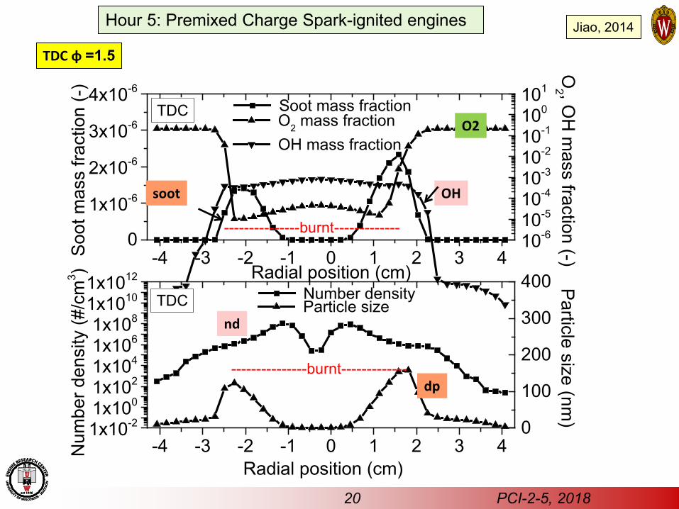
TDC φ =1.5
nd
dp
O2
OH soot
---------------burnt-------------
---------------burnt-------------
20 PCI-2-5, 2018
Jiao, 2014 Hour 5: Premixed Charge Spark-ignited engines
-4 -3 -2 -1 0 1 2 3 40
2x10⁻⁷
4x10⁻⁷
6x10⁻⁷
8x10⁻⁷
1x10⁻⁶
Soot mass fraction
Radial position (cm)
800 aTDC
02x10-5
4x10⁻⁵
6x10⁻⁵
8x10⁻⁵
1x10⁻⁴
O2 mass fraction OH mass fraction
O2 , O
H m
ass fraction (-)
Soot
mas
s fra
ctio
n (-)
-4 -3 -2 -1 0 1 2 3 41x10-21x1001x1021x1041x1061x108
800 aTDC Number density
Num
ber d
ensi
ty (#
/cm
3 )
Particle size (nm)
Radial position (cm)
0100200300400500
Particle size
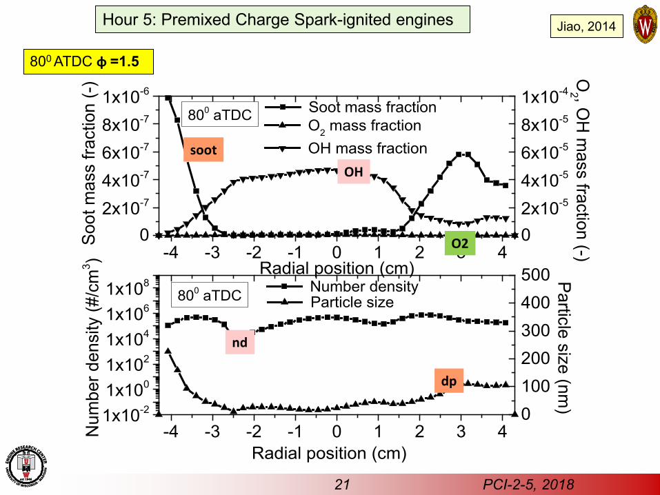
800 ATDC φ =1.5
soot
O2
OH
dp
nd
21 PCI-2-5, 2018
Jiao, 2014 Hour 5: Premixed Charge Spark-ignited engines
10 1001x102
1x10³
1x10⁴
1x10⁵
1x10⁶
1x10⁷
1x10⁸
1x10⁹
1x10¹⁰
dN/d
log(
d p) (#
/cm
3 )
dp (nm)
0.8; 0.26 0.98; 0.33 1.2; 0.41 1.3; 0.44 1.4; 0.48 1.5; 0.51
Φ; C/O
referenceexpt
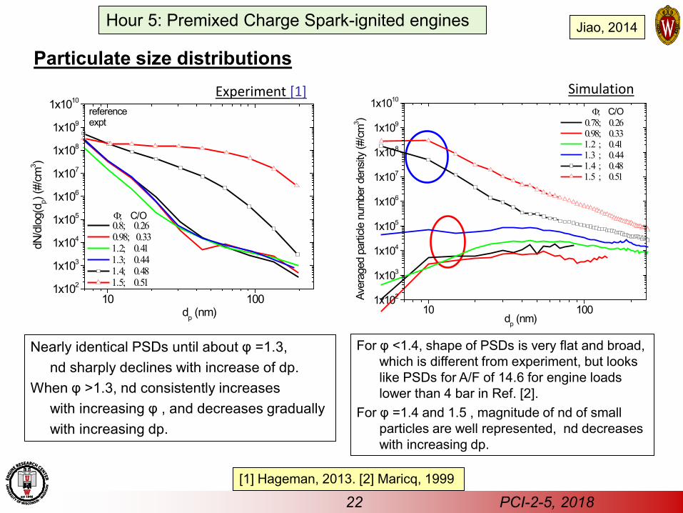
Experiment [1] Simulation
Nearly identical PSDs until about φ =1.3, nd sharply declines with increase of dp. When φ >1.3, nd consistently increases with increasing φ , and decreases gradually with increasing dp.
For φ <1.4, shape of PSDs is very flat and broad, which is different from experiment, but looks like PSDs for A/F of 14.6 for engine loads lower than 4 bar in Ref. [2].
For φ =1.4 and 1.5 , magnitude of nd of small particles are well represented, nd decreases with increasing dp.
[1] Hageman, 2013. [2] Maricq, 1999
10 1001x102
1x10³
1x10⁴
1x10⁵
1x10⁶
1x10⁷
1x10⁸
1x10⁹
1x10¹⁰
Aver
aged
par
ticle
num
ber d
ensit
y (#
/cm
3 )
dp (nm)
0.78; 0.26 0.98; 0.33 1.2 ; 0.41 1.3 ; 0.44 1.4 ; 0.48 1.5 ; 0.51
Φ; C/O
22 PCI-2-5, 2018
Jiao, 2014
Particulate size distributions
Hour 5: Premixed Charge Spark-ignited engines
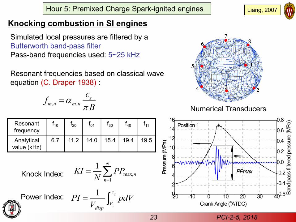
Knocking combustion in SI engines
-20 -10 0 10 20 30 400
2
4
6
8
10
12
14
16
-0.6
-0.4
-0.2
0.0
0.2
0.4
0.6
0.8
Pres
sure
(MPa
)
Crank Angle (oATDC)
Position 1
Band
-pas
s filt
ered
pre
ssur
e (M
Pa)
PPmax
Simulated local pressures are filtered by a Butterworth band-pass filter Pass-band frequencies used: 5~25 kHz
Knock Index: max,1
1 N
nn
KI PPN =
= ∑
Power Index: 2
1
1 V
Vdisp
PI pdVV
= ∫
Numerical Transducers
Resonant frequencies based on classical wave equation (C. Draper 1938) :
Resonant frequency
f10 f20 f01 f30 f40 f11
Analytical value (kHz)
6.7 11.2 14.0 15.4 19.4 19.5
, ,s
m n m ncfB
απ
=
23 PCI-2-5, 2018
Liang, 2007 Hour 5: Premixed Charge Spark-ignited engines
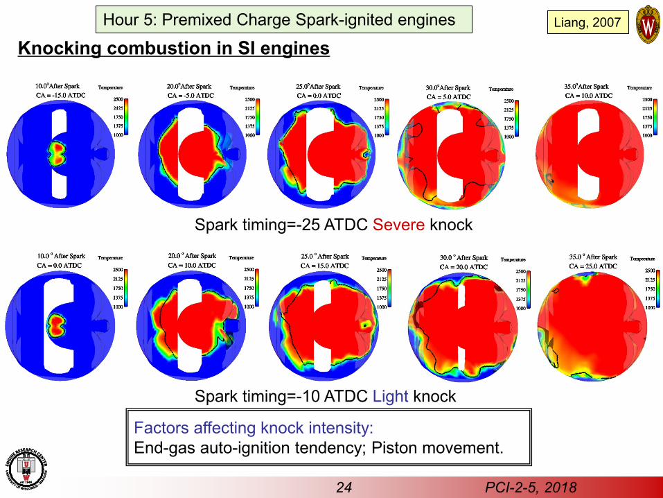
Factors affecting knock intensity: End-gas auto-ignition tendency; Piston movement.
Spark timing=-10 ATDC Light knock
Spark timing=-25 ATDC Severe knock
Knocking combustion in SI engines
24 PCI-2-5, 2018
Liang, 2007 Hour 5: Premixed Charge Spark-ignited engines
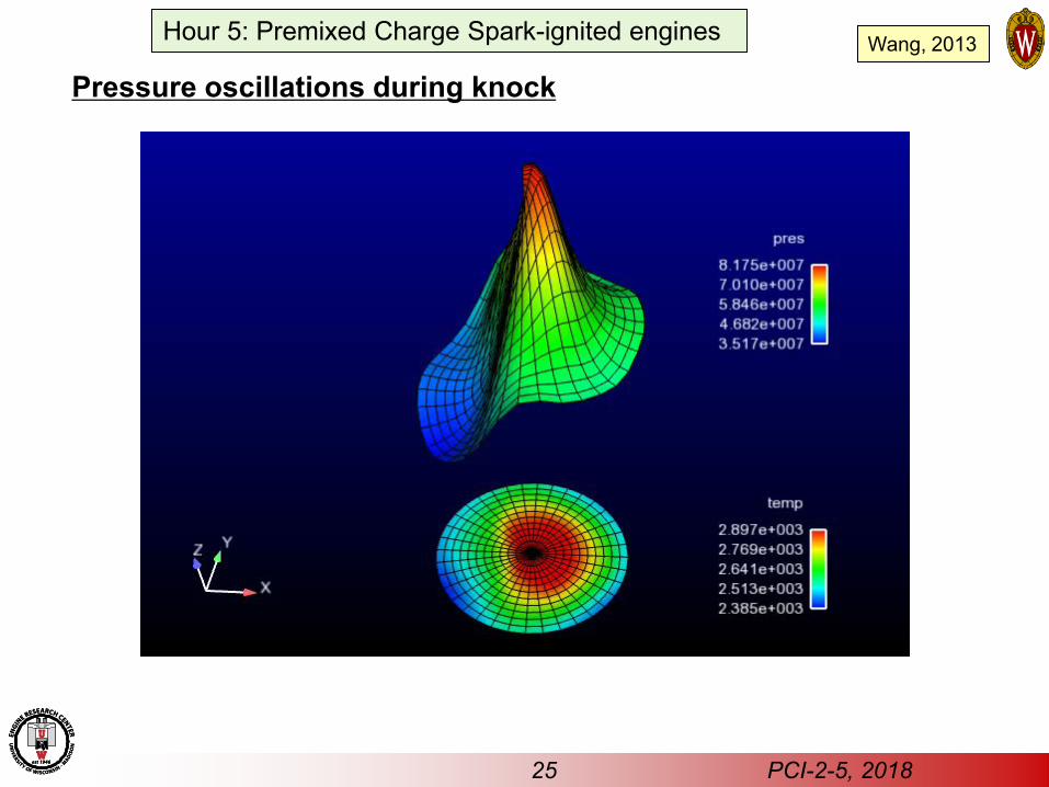
Pressure oscillations during knock
25 PCI-2-5, 2018
Wang, 2013 Hour 5: Premixed Charge Spark-ignited engines
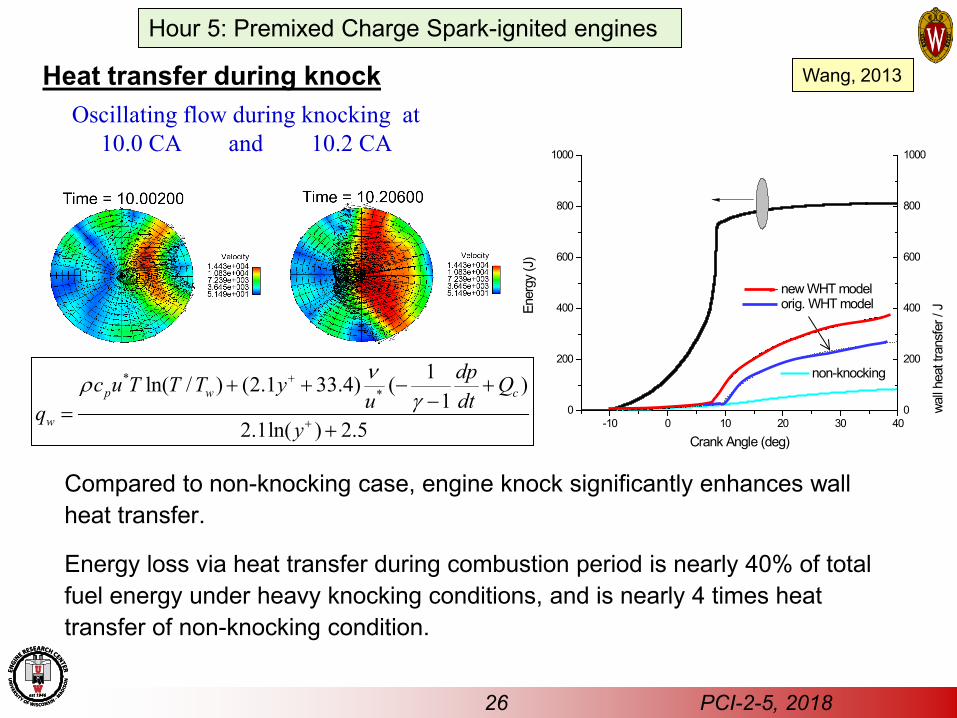
Heat transfer during knock
Compared to non-knocking case, engine knock significantly enhances wall heat transfer.
Energy loss via heat transfer during combustion period is nearly 40% of total fuel energy under heavy knocking conditions, and is nearly 4 times heat transfer of non-knocking condition.
Oscillating flow during knocking at 10.0 CA and 10.2 CA
**
1ln( / ) (2.1 33.4) ( )1
2.1ln( ) 2.5
p w c
w
dpc u T T T y Qu dtq
y
νργ
+
+
+ + − +−=
+ -10 0 10 20 30 400
200
400
600
800
1000
wall h
eat t
rans
fer /
JEner
gy (J
)
Crank Angle (deg)
non-knocking
0
200
400
600
800
1000
new WHT model orig. WHT model
26 PCI-2-5, 2018
Wang, 2013
Hour 5: Premixed Charge Spark-ignited engines

27 PCI-2-5, 2018
“Superknock - stochastic pre-ignition” Super-knock is severe engine knock triggered by pre-ignition randomly, sometimes after many thousands of engine cycles
Wang, 2014 Kalghatgi, 2018
Hour 5: Premixed Charge Spark-ignited engines
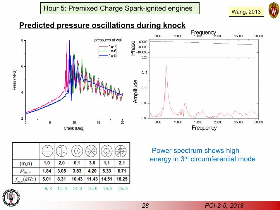
Predicted pressure oscillations during knock
0 5 10 15 202
4
6
8
Pres
s (M
Pa)
Crank (Deg)
1e-7 1e-6 1e-5
pressures at wall
5000 10000 15000 20000 25000 300000.00
0.05
0.10
0.15
0.20
FrequencyAm
plitu
de
-100000-80000-60000
5000 10000 15000 20000 25000 30000Frequency
Phas
e
Power spectrum shows high energy in 3rd circumferential mode
Wang, 2013
28 PCI-2-5, 2018
Hour 5: Premixed Charge Spark-ignited engines

29 PCI-2-5, 2018
Hour 5: Premixed Charge Spark-ignited engines
Summary: Auto-ignition chemistry alone is NOT sufficient to properly model flame propagation.
Turbulence enhancing effect on flame propagation speed in SI engines CANNOT be neglected. Gasoline engine particulate emissions originate in the flame brush and soot particle sizes can be predicted reasonably well. Knocking combustion CFD simulations require refined numerical time steps to resolve detonation wave propagation physics
30 PCI-2-5, 2018
Hour 5: Premixed Charge Spark-ignited engines
References 2-5:3 Liang, L.; Reitz, R.D., "Spark Ignition Engine Combustion Modeling Using a Level Set Method with Detailed Chemistry," SAE Paper 2006-01-0243, 2006
2-5:4 C.K. Law, Private communication, University of Wisconsin-Madison, 2014
2-5:5 Reitz, R.D., "A Study of Numerical Methods for Reaction-Diffusion Equations," SIAM Journal on Scientific and Statistical Computing, Vol. 2, p. 95, 1981.
2-5:6,7,9-14,23,24 Liang, L., Reitz, R.D., Iyer, C.O. and Yi, J., "Modeling Knock in Spark-Ignition Engines Using a G-equation Combustion Model Incorporating Detailed Chemical Kinetics," SAE paper 2007-01-0165, 2007.
2-5:6 J. Ghandhi, private communication, University of Wisconsin-Madison, 2012.
2-5:6,7 Peters, N. Turbulent Combustion, Cambridge University Press, 2000
2-5:7 Fan, Li, and Reitz, R.D., “Development of an Ignition and Combustion Model for Spark-Ignition Engines,” SAE Paper 2000-01-2809, SAE Transactions, Journal of Engines, Vol. 109, Section 3, pp. 1977-1989, 2000.
2-5:8 Farrell, J., Private communication, University of Wisconsin-Madison, 2005.
2-5:15 Kittelson, D.B., "Engines and Nanoparticles: A Review," Journal of Aerosol Science, 29(5–6): 575-588, (1998).
2-5:16 Vishwanathan, G., and Reitz, R.D.,”Development of a Practical Soot Modeling Approach and its Application to Low Temperature Diesel Combustion,” Combustion Science and Technology, Vol. 182, Issue 8, pp.1050-1082, 2010.
2-5:16 Wang, H., Ra, Y., Jia, M., and Reitz, R.D., “Development of a reduced n-dodecane-PAH mechanism and its Application for n-dodecane Soot Predictions,” Submitted, FUEL, 2014
2-5:17-22 Jiao, Q., and Reitz, R.D., "Modeling of Equivalence Ratio Effects on Particulate Formation in a Spark-Ignition Engine under Premixed Conditions," SAE Technical Paper 2014-01-1607, 2014
2-5:22 Hageman, M., Rothamer, D., Sensitivity Analysis of Particle Formation in a Spark-Ignition Engine during Premixed Operation, in 8th U.S. National Combustion Meeting, 2013.
31 PCI-2-5, 2018
Hour 5: Premixed Charge Spark-ignited engines
References
2-5:22 Maricq, M.M., Podsiadlik, D. H., Brehob, D. D., Haghgooie, M., Particulate Emissions from a Direct-Injection Spark-Ignition (DISI) Engine, 1999, SAE1999-01-1530.
2-5:25,26 Wang, Z., Wang, Y., and Reitz, R.D., "Pressure Oscillation and Chemical Kinetics Coupling during Knock Processes in Gasoline Engine Combustion" Energy & Fuels, Vol. 26 (12), pp. 7107–7119, 2012, DOI: 10.1021/ef301472g. – see also Vol. 27 (1), pp. 599-599, 2013.
2-5:27 Zhi Wang, Hui Liu, Tao Song, Yunliang Qi, Xin He, Shijin Shuai and Jian Xin Wang, “Relationship between super-knock and pre-ignition,” International Journal of Engine Research, 2014. DOI: 10.1177/1468087414530388.
2-5:27 Kalghatgi, G., “Knock onset, knock intensity, superknock and preignition in spark ignition engines,” International Journal of Engine Research, Vol. 19, pp. 7-20, 2018.