Embed Size (px)
Citation preview
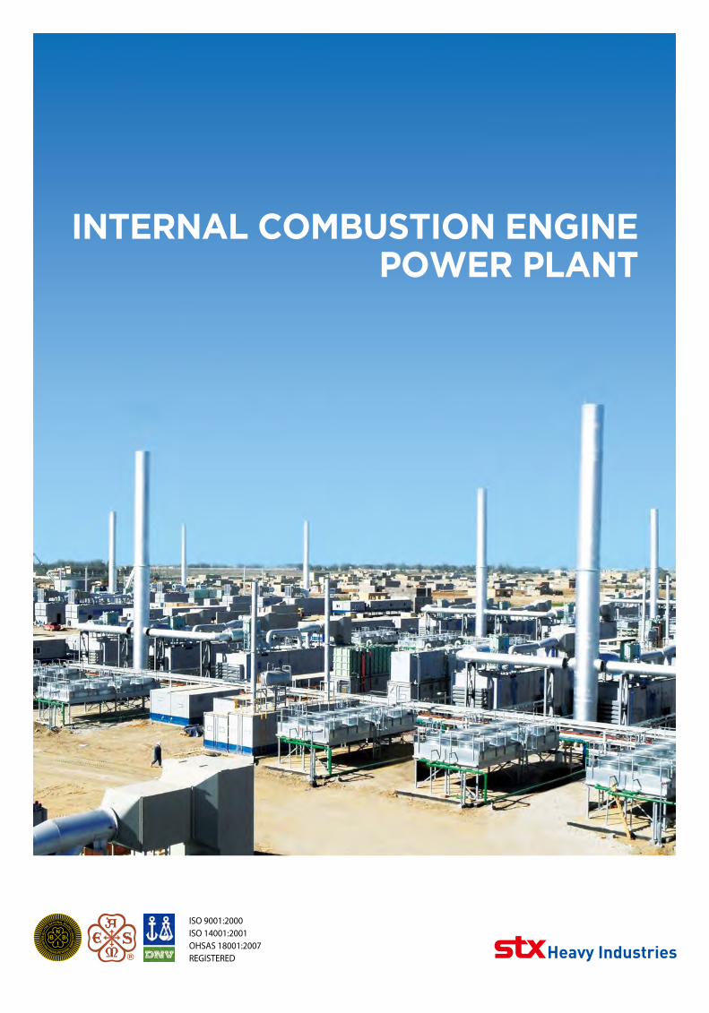
Internal CombustIon engIne Power Plant
ISO 9001:2000ISO 14001:2001OHSAS 18001:2007REGISTERED
2 Internal Combustion Engine Power Plant 3
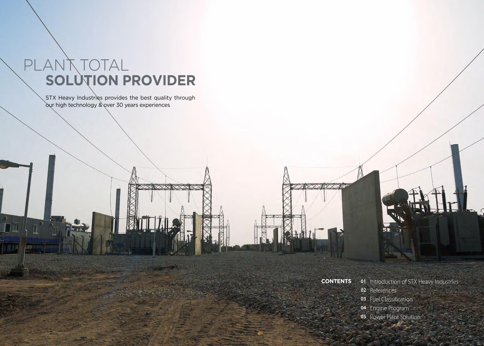
01 Introduction of STX Heavy Industries02 References03 Fuel Classification04 Engine Program05 Power Plant Solution
Plant total solutIon ProvIder
Contents
STX Heavy Industries provides the best quality through our high technology & over 30 years experiences
4 Internal Combustion Engine Power Plant 5
09
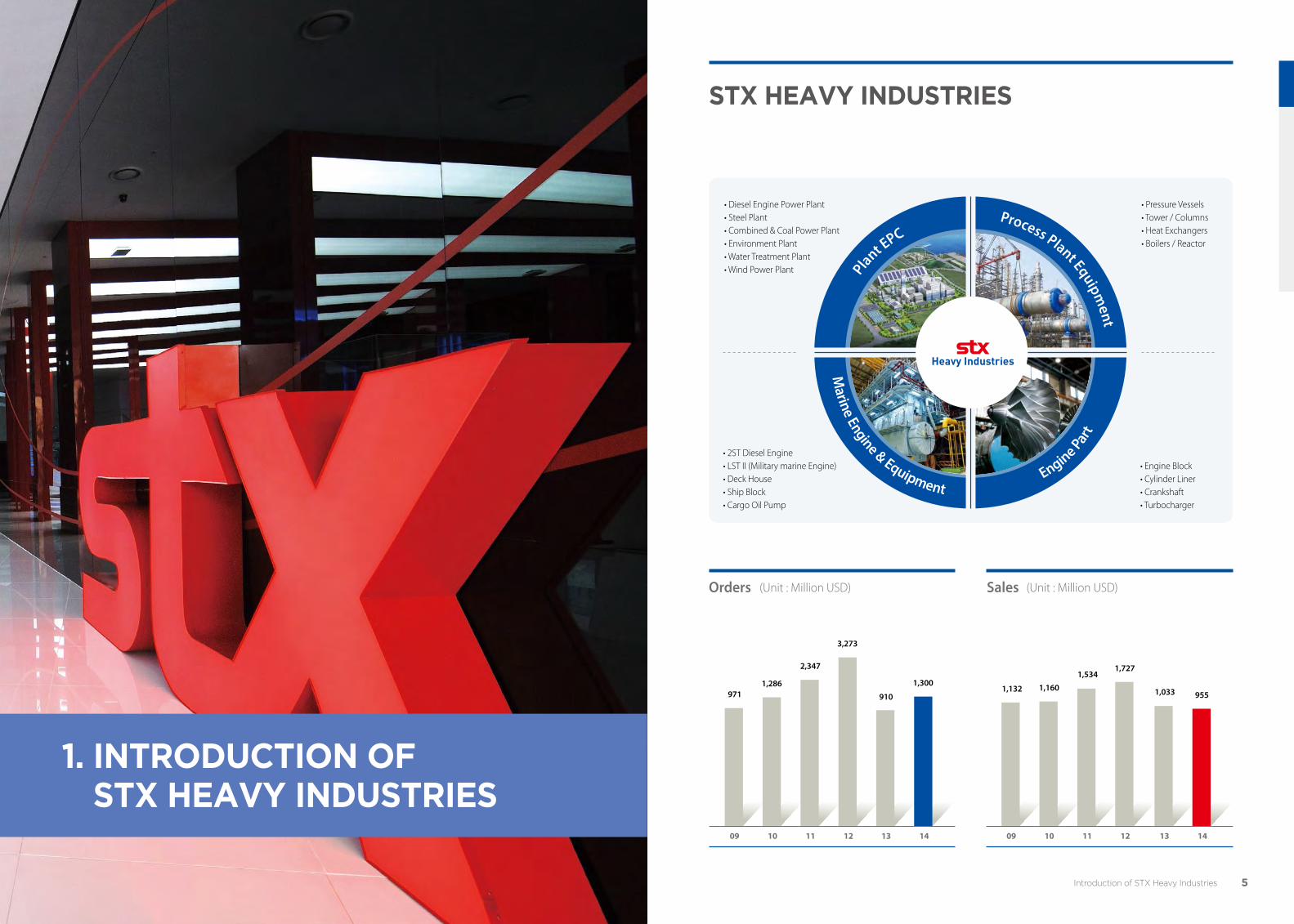
971
10
1,286
11
2,347
12
3,273
09
1,132
10
1,160
11
1,534
12
1,727
910
1,3001,033 955
Introduction of StX Heavy Industries
1. IntroduCtIon of stX Heavy IndustrIes
SalesOrders
13 14 13 14
(Unit : Million USD)(Unit : Million USD)
• Diesel Engine Power Plant• Steel Plant• Combined & Coal Power Plant• Environment Plant• Water Treatment Plant• Wind Power Plant
stX Heavy IndustrIes
• Pressure Vessels• Tower / Columns• Heat Exchangers• Boilers / Reactor
• Engine Block• Cylinder Liner• Crankshaft• Turbocharger
• 2ST Diesel Engine• LST II (Military marine Engine)• Deck House• Ship Block• Cargo Oil Pump
Plant EPC
Marine Engine & Equipment
Engine Part
Process Plant Equipment
6 Internal Combustion Engine Power Plant 7
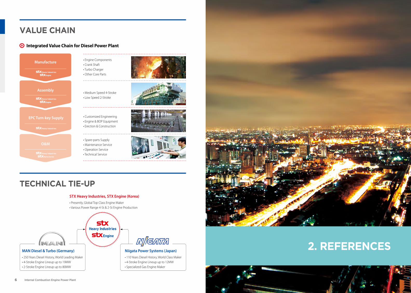
• Engine Components• Crank Shaft• Turbo Charger• Other Core Parts
• Customized Engineering• Engine & BOP Equipment• Erection & Construction
teCHnICal tIe-uPSTX Heavy Industries, STX Engine (Korea)• Presently, Global Top Class Engine Maker• Various Power Range 4-St & 2-St Engine Production
• Medium Speed 4-Stroke• Low Speed 2-Stroke
• Spare-parts Supply• Maintenance Service• Operation Service• Technical Service
Manufacture
Integrated Value Chain for Diesel Power Plant
Assembly
EPC Turn-key Supply
O&M
value CHaIn
2. referenCesMAN Diesel & Turbo (Germany)• 250 Years Diesel History, World Leading Maker• 4-Stroke Engine Lineup up to 19MW• 2-Stroke Engine Lineup up to 80MW
Niigata Power Systems (Japan)• 110 Years Diesel History, World Class Maker• 4-Stroke Engine Lineup up to 12MW• Specialized Gas Engine Maker
8 Internal Combustion Engine Power Plant 9References
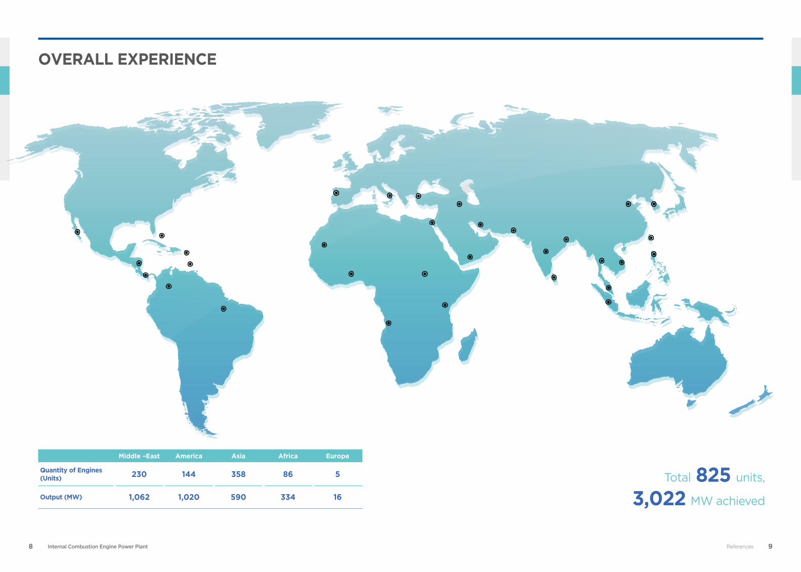
units,825Total
MW achieved3,022
Overall experience
Middle –east america asia africa europe
Quantity of engines (Units) 230 144 358 86 5
Output (MW) 1,062 1,020 590 334 16

10 Internal Combustion Engine Power Plant 11
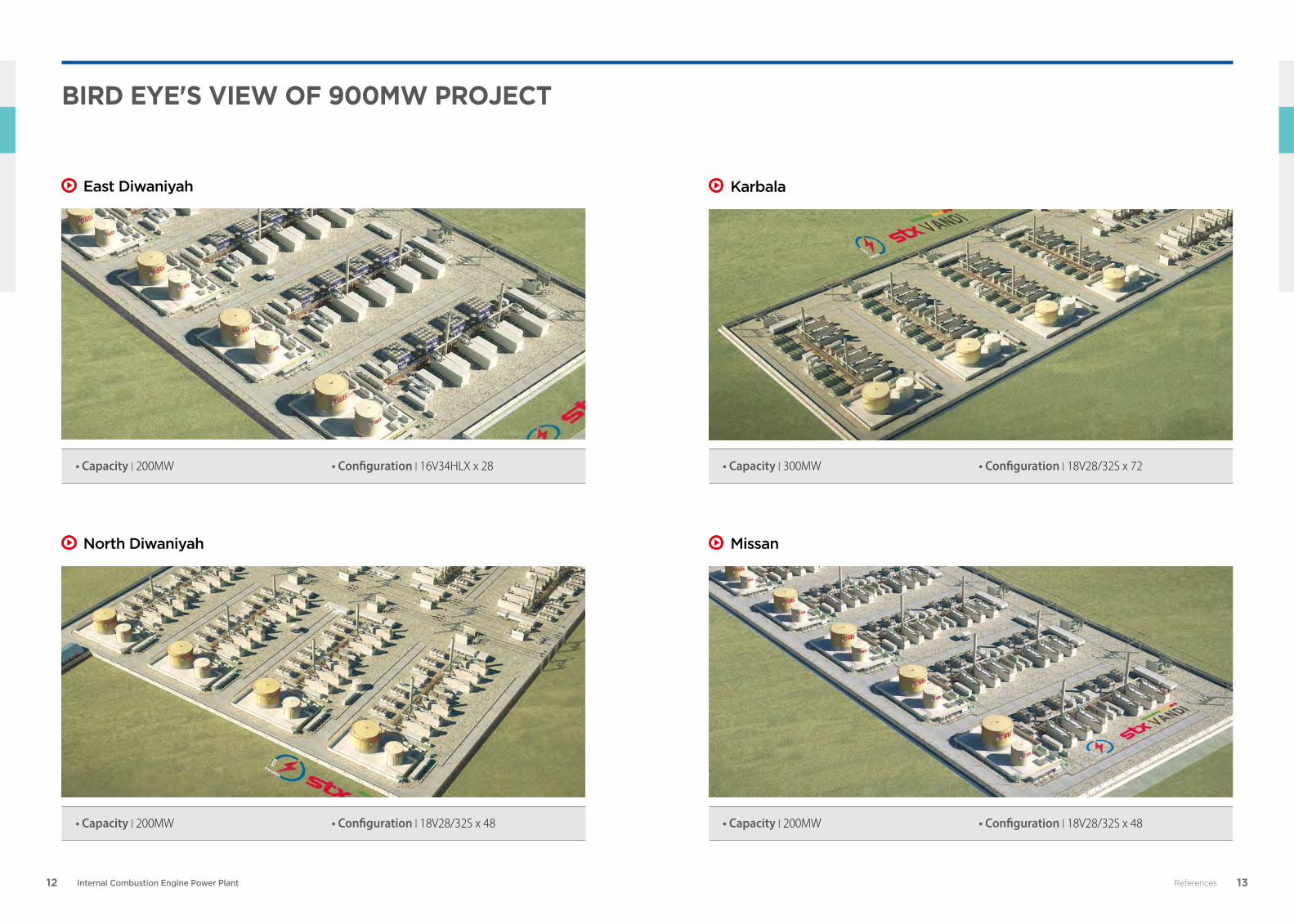
In June 2012, STX Heavy Industries commissioned 900MW diesel power plant for Ministry of Electricity, Iraq. STX Heavy Industries, the main contractor had executed EPC (Engineering, Procurement, and Construction) project. This project consists of total 4 sites, East Diwaniyah, North Diwaniyah, Missan and Karbala.
Within only 11 months, STX Heavy Industries had completed manufacture, transport, installation and commissioning. For this project, 196 diesel generator sets had been manufactured & commissioned.
Customer Ministry of Electricity, Iraq
Location Iraq
Work Scope EPC
Fuel Type HFO, DO
Total Capacity 900MW
Engine Model STX-NIIGATA 16V34HLX x 28STX-MAN 18V28/32S x 168
Commercial Operation Date July 2012
900MW EPC ProjECt Iraq
References
12 Internal Combustion Engine Power Plant 13
• Capacity | 300MW • Configuration | 18V28/32S x 72
• Capacity | 200MW • Configuration | 18V28/32S x 48• Capacity | 200MW • Configuration | 18V28/32S x 48
References
East Diwaniyah Karbala
North Diwaniyah Missan
• Capacity | 200MW • Configuration | 16V34HLX x 28
bIrd eye's vIew of 900mw ProjeCt
14 Internal Combustion Engine Power Plant 15References
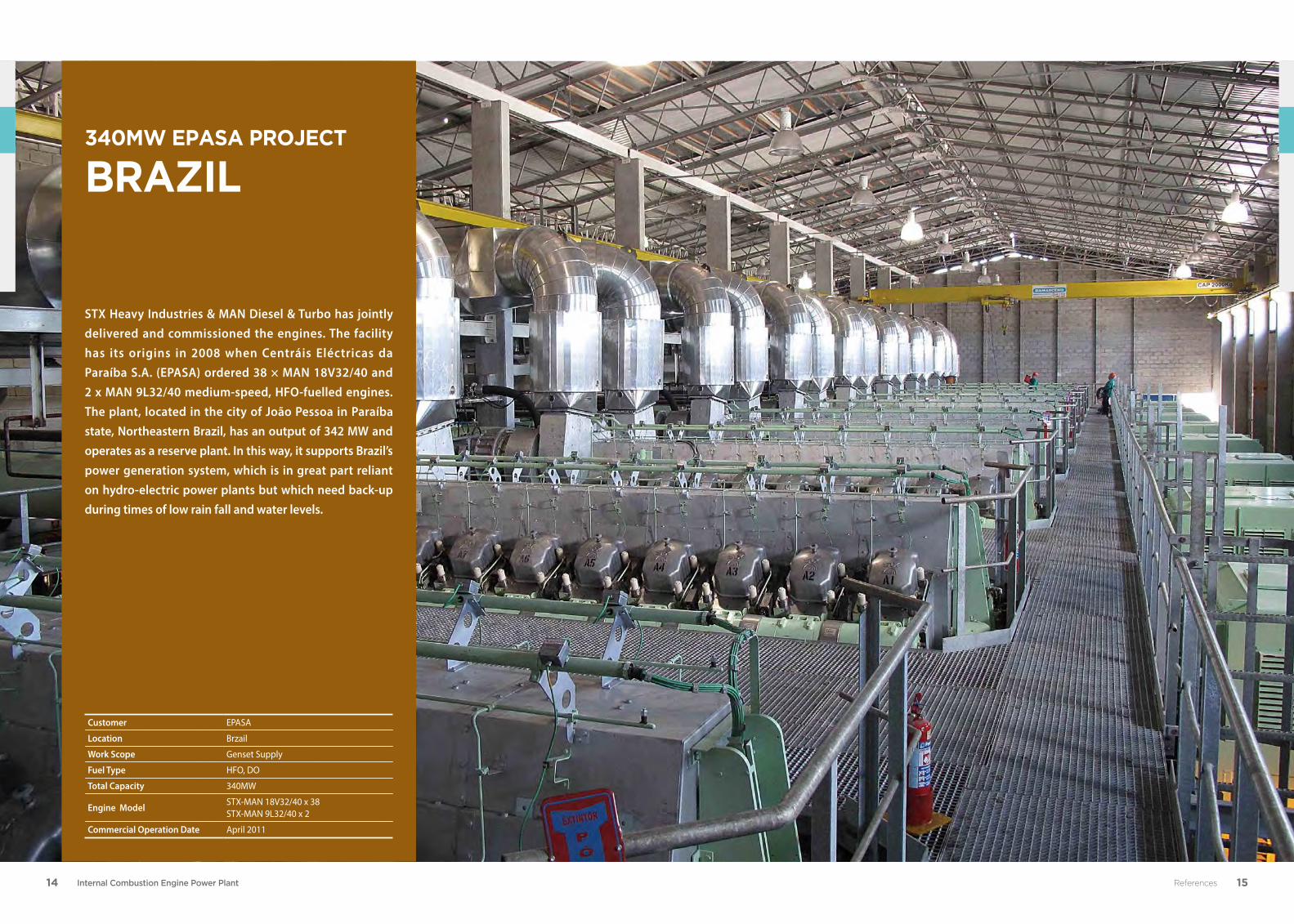
STX Heavy Industries & MAN Diesel & Turbo has jointly delivered and commissioned the engines. The facility has its origins in 2008 when Centráis Eléctricas da Paraíba S.A. (EPASA) ordered 38 × MAN 18V32/40 and 2 x MAN 9L32/40 medium-speed, HFO-fuelled engines. The plant, located in the city of João Pessoa in Paraíba state, Northeastern Brazil, has an output of 342 MW and operates as a reserve plant. In this way, it supports Brazil’s power generation system, which is in great part reliant on hydro-electric power plants but which need back-up during times of low rain fall and water levels.
Customer EPASA
Location Brzail
Work Scope Genset Supply
Fuel Type HFO, DO
Total Capacity 340MW
Engine Model STX-MAN 18V32/40 x 38STX-MAN 9L32/40 x 2
Commercial Operation Date April 2011
340mw ePasa ProjeCt braZIl
16 Internal Combustion Engine Power Plant 17References
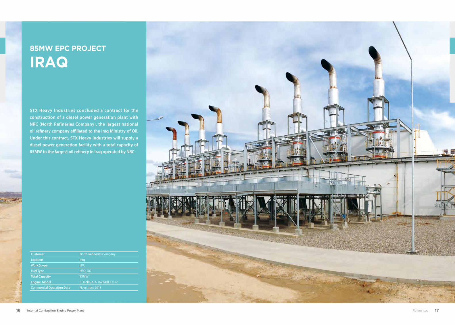
STX Heavy Industries concluded a contract for the construction of a diesel power generation plant with NRC (North Refineries Company), the largest national oil refinery company affiliated to the Iraq Ministry of Oil. Under this contract, STX Heavy Industries will supply a diesel power generation facility with a total capacity of 85MW to the largest oil refinery in Iraq operated by NRC.
85MW EPC ProjECt Iraq
Customer North Refineries Company
Location Iraq
Work Scope EPC
Fuel Type HFO, DO
Total Capacity 85MW
Engine Model STX-NIIGATA 16V34HLX x 12
Commercial Operation Date November 2013
18 Internal Combustion Engine Power Plant 19
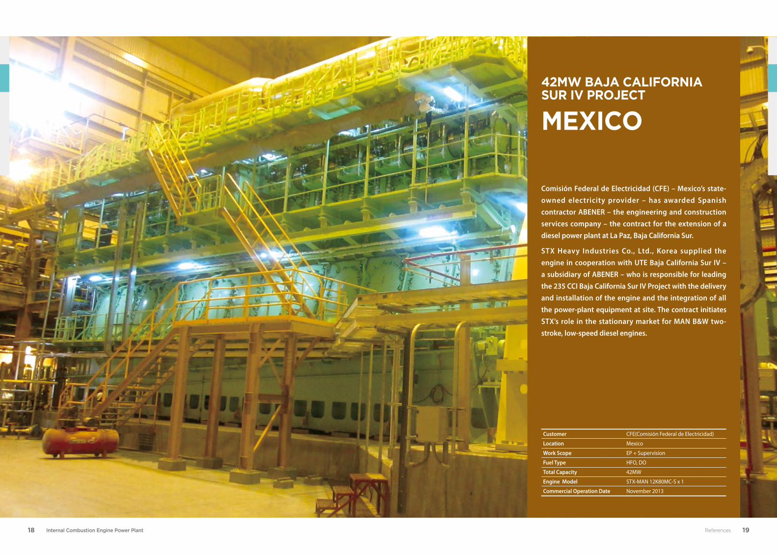
Comisión Federal de Electricidad (CFE) – Mexico’s state-owned electricity provider – has awarded Spanish contractor ABENER – the engineering and construction services company – the contract for the extension of a diesel power plant at La Paz, Baja California Sur.
STX Heavy Industries Co., Ltd., Korea supplied the engine in cooperation with UTE Baja California Sur IV – a subsidiary of ABENER – who is responsible for leading the 235 CCI Baja California Sur IV Project with the delivery and installation of the engine and the integration of all the power-plant equipment at site. The contract initiates STX’s role in the stationary market for MAN B&W two-stroke, low-speed diesel engines.
Customer CFE(Comisión Federal de Electricidad)
Location Mexico
Work Scope EP + Supervision
Fuel Type HFO, DO
Total Capacity 42MW
Engine Model STX-MAN 12K80MC-S x 1
Commercial Operation Date November 2013
42MW Baja California Sur iV ProjeCt
MexiCo
References
20 Internal Combustion Engine Power Plant 21References
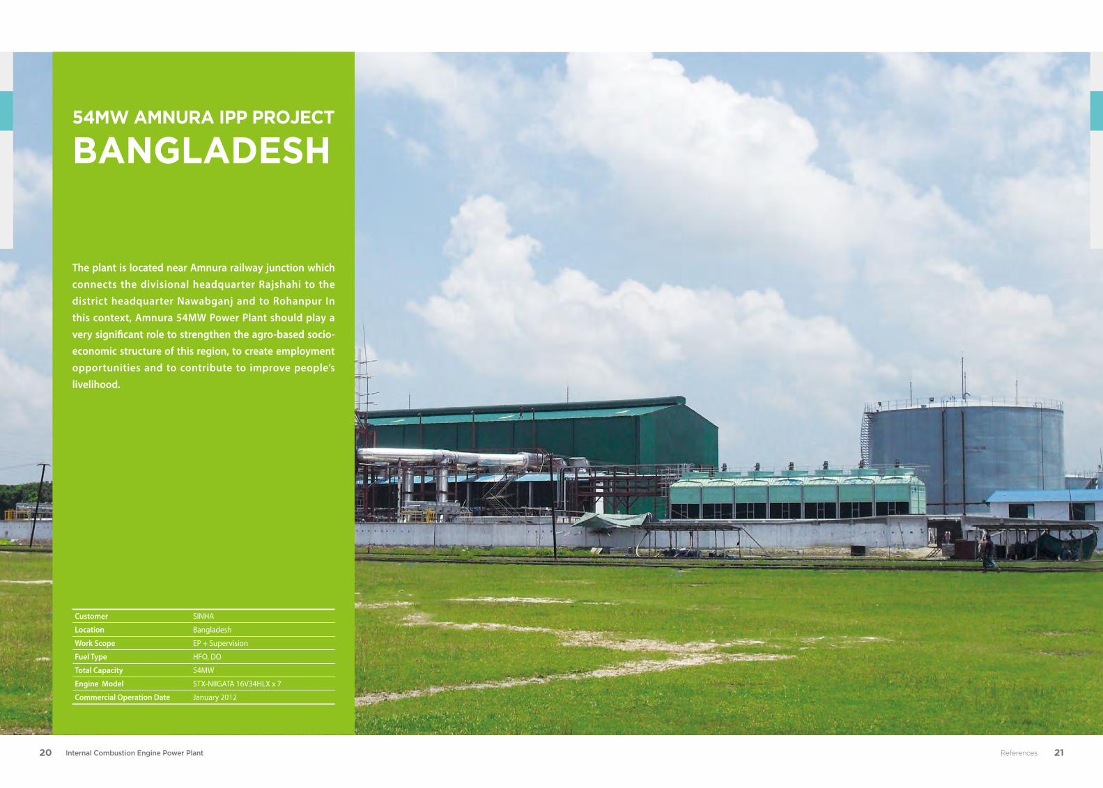
The plant is located near Amnura railway junction which connects the divisional headquarter Rajshahi to the district headquarter Nawabganj and to Rohanpur In this context, Amnura 54MW Power Plant should play a very significant role to strengthen the agro-based socio-economic structure of this region, to create employment opportunities and to contribute to improve people’s livelihood.
54MW AMnurA IPP Project BAnglAdesh
Customer SINHA
Location Bangladesh
Work Scope EP + Supervision
Fuel Type HFO, DO
Total Capacity 54MW
Engine Model STX-NIIGATA 16V34HLX x 7
Commercial Operation Date January 2012
22 Internal Combustion Engine Power Plant 23References
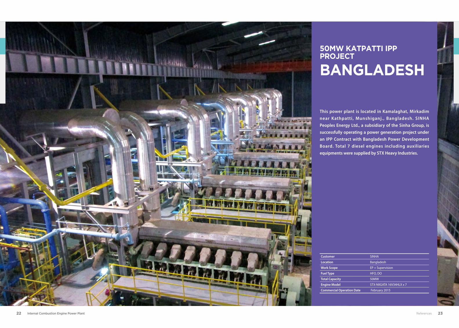
This power plant is located in Kamalaghat, Mirkadim near Kathpatti , Munshiganj. , Bangladesh. SINHA Peoples Energy Ltd., a subsidiary of the Sinha Group, is successfully operating a power generation project under an IPP Contract with Bangladesh Power Development Board. Total 7 diesel engines including auxiliaries equipments were supplied by STX Heavy Industries.
Customer SINHA
Location Bangladesh
Work Scope EP + Supervision
Fuel Type HFO, DO
Total Capacity 50MW
Engine Model STX-NIIGATA 16V34HLX x 7
Commercial Operation Date February 2015
50MW KATPATTI IPP PROJECT
BANGLADESH
24 Internal Combustion Engine Power Plant 25References
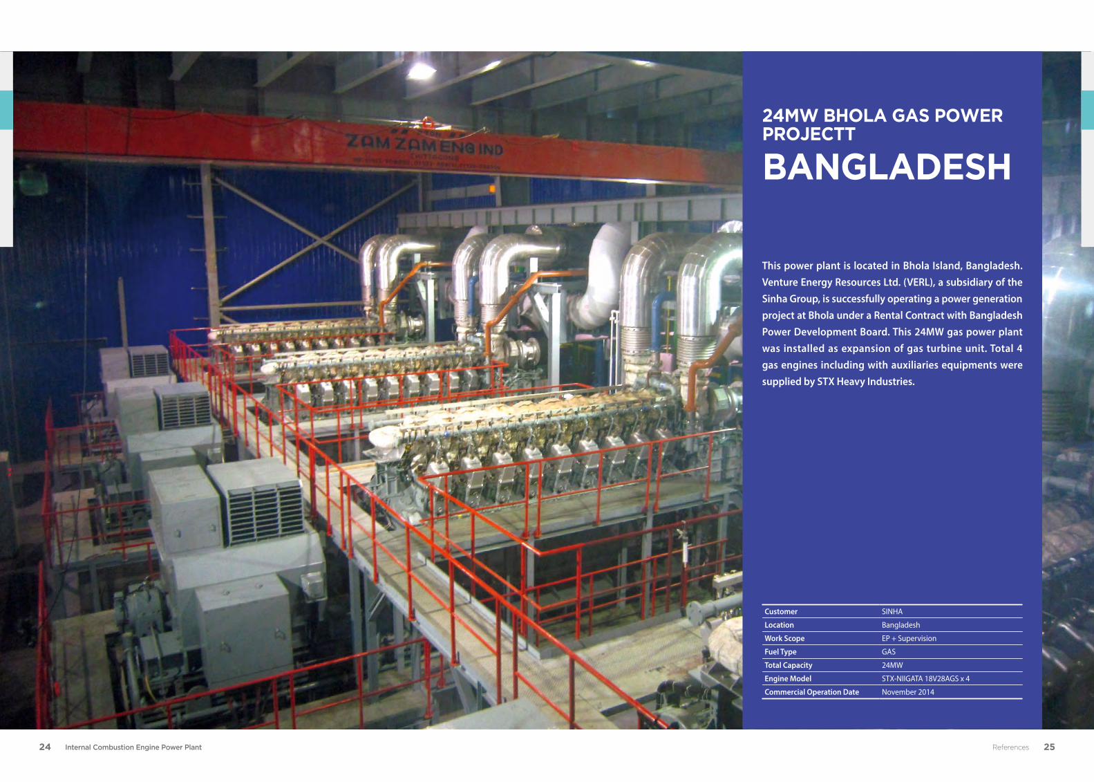
This power plant is located in Bhola Island, Bangladesh. Venture Energy Resources Ltd. (VERL), a subsidiary of the Sinha Group, is successfully operating a power generation project at Bhola under a Rental Contract with Bangladesh Power Development Board. This 24MW gas power plant was installed as expansion of gas turbine unit. Total 4 gas engines including with auxiliaries equipments were supplied by STX Heavy Industries.
Customer SINHA
Location Bangladesh
Work Scope EP + Supervision
Fuel Type GAS
Total Capacity 24MW
Engine Model STX-NIIGATA 18V28AGS x 4
Commercial Operation Date November 2014
24MW BHOLA GAS POWER PROJECTT
BANGLADESH
26 Internal Combustion Engine Power Plant 27References
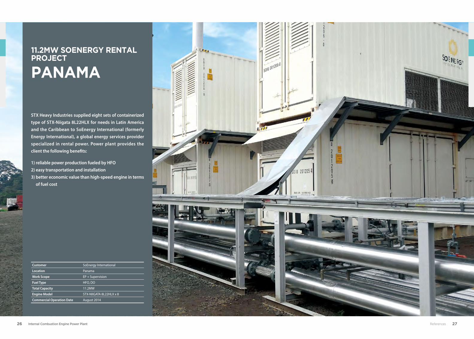
STX Heavy Industries supplied eight sets of containerized type of STX-Niigata 8L22HLX for needs in Latin America and the Caribbean to SoEnergy International (formerly Energy International), a global energy services provider specialized in rental power. Power plant provides the client the following benefits:
1) reliable power production fueled by HFO 2) easy transportation and installation 3) better economic value than high-speed engine in terms
of fuel cost
Customer SoEnergy International
Location Panama
Work Scope EP + Supervision
Fuel Type HFO, DO
Total Capacity 11.2MW
Engine Model STX-NIIGATA 8L22HLX x 8
Commercial Operation Date August 2014
11.2MW SOENERGY RENTAL PROJECT
PANAMA
28 Internal Combustion Engine Power Plant 29
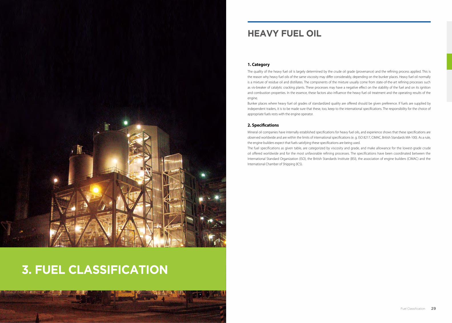
3. fuel ClassIfICatIon
Heavy fuel oIl
1. CategoryThe quality of the heavy fuel oil is largely determined by the crude oil grade (provenance) and the refining process applied. This is
the reason why heavy fuel oils of the same viscosity may differ considerably, depending on the bunker places. Heavy fuel oil normally
is a mixture of residue oil and distillates. The components of the mixture usually come from state-of-the-art refining processes such
as vis-breaker of catalytic cracking plants. These processes may have a negative effect on the stability of the fuel and on its ignition
and combustion properties. In the essence, these factors also influence the heavy fuel oil treatment and the operating results of the
engine.
Bunker places where heavy fuel oil grades of standardized quality are offered should be given preference. If fuels are supplied by
independent traders, it is to be made sure that these, too, keep to the international specifications. The responsibility for the choice of
appropriate fuels rests with the engine operator.
2. SpecificationsMineral oil companies have internally established specifications for heavy fuel oils, and experience shows that these specifications are
observed worldwide and are within the limits of international specifications (e. g. ISO 8217, CIMAC, British Standards MA-100). As a rule,
the engine builders expect that fuels satisfying these specifications are being used.
The fuel specifications as given table, are categorized by viscosity and grade, and make allowance for the lowest-grade crude
oil offered worldwide and for the most unfavorable refining processes. The specifications have been coordinated between the
International Standard Organization (ISO), the British Standards Institute (BSI), the association of engine builders (CIMAC) and the
International Chamber of Shipping (ICS).
Fuel Classification
30 Internal Combustion Engine Power Plant 31Fuel Classification
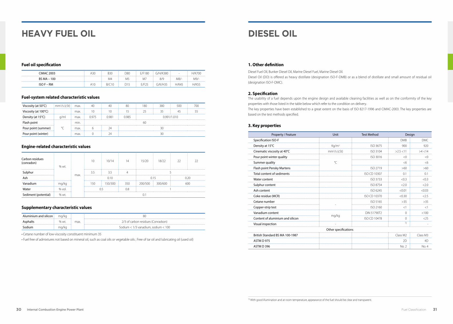
Fuel oil specification
CIMAC 2003 A30 B30 D80 E/F180 G/H/K380 - H/K700
BS MA – 100 M4 M5 M7 8/9 M8/- M9/-
ISO F – RM A10 B/C10 D15 E/F25 G/K/H35 H/K45 H/K55
Fuel-system related characteristic values
Viscosity (at 50°C) mm2/s (cSt) max. 40 40 80 180 380 500 700
Viscosity (at 100°C) max. 10 10 15 25 35 45 55
Density (at 15°C) g/ml max. 0.975 0.981 0.985 0.991/1.010
Flash point
°C
min. 60
Pour point (summer) max. 6 24 30
Pour point (winter) max. 0 24 30
Engine-related characteristic values
Carbon residues (conradon)
% wt.
max.
10 10/14 14 15/20 18/22 22 22
Sulphur 3.5 3.5 4 5
Ash 0.10 0.15 0.20
Vanadium mg/kg 150 150/300 350 200/500 300/600 600
Water % vol. 0.5 0.8 1
Sediment (potential) % wt. 0.1
Supplementary characteristic values
Aluminium and silicon mg/kg
max.
80
Asphalts % wt. 2/3 of carbon residues (Conradson)
Sodium mg/kg Sodium < 1/3 vanadium, sodium < 100
• Cetane number of low-viscosity constituent minimum 35
• Fuel free of admixtures not based on mineral oil, such as coal oils or vegetable oils ; Free of tar oil and lubricating oil (used oil)
Heavy fuel oIl dIesel oIl
1. Other definition Diesel Fuel Oil, Bunker Diesel Oil, Marine Diesel Fuel, Marine Diesel Oil.
Diesel Oil (DO) is offered as heavy distillate (designation ISO-F-DMB) or as a blend of distillate and small amount of residual oil
(designation ISO-F-DMC).
2. SpecificationThe usability of a fuel depends upon the engine design and available cleaning facilities as well as on the conformity of the key
properties with those listed in the table below which refer to the condition on delivery.
The key properties have been established to a great extent on the basis of ISO 8217-1996 and CIMAC-2003. The key properties are
based on the test methods specified.
3. Key properties
Property / Feature Unit Test Method Design
Specification ISO-F DMB DMC
Density at 15°C Kg/m3 ISO 3675 900 920
Cinematic viscosity at 40°C mm2/s (cSt) ISO 3104 >2.5 <11 >4 <14
Pour point winter quality
°C
ISO 3016 <0 <0
Summer quality <6 <6
Flash point Pensky Martens ISO 2719 >60 >60
Total content of sediments ISO CD 10307 0.1 0.1
Water content ISO 3733 <0.3 <0.3
Sulphur content ISO 8754 <2.0 <2.0
Ash content ISO 6245 <0.01 <0.03
Coke residue (MCR) ISO CD 10370 <0.30 <2.5
Cetane number-
ISO 5165 >35 >35
Copper-strip test ISO 2160 <1 <1
Vanadium contentmg/kg
DIN 51790T2 0 <100
Content of aluminium and silicon ISO CD 10478 0 <25
Visual inspection - 1) -
Other specifications
British Standard BS MA 100-1987 Class M2 Class M3
ASTM D 975 2D 4D
ASTM D 396 No. 2 No. 4
1) With good illumination and at room temperature, appearance of the fuel should be clear and transparent.
32 Internal Combustion Engine Power Plant 33Fuel Classification
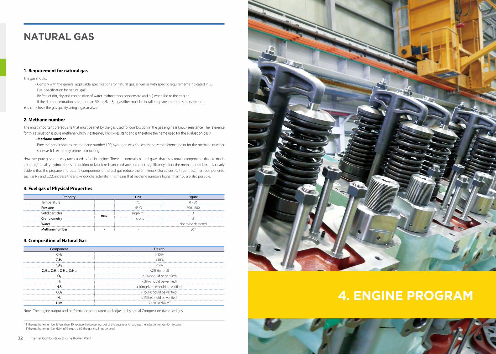
4. engIne Program
natural gas
1. Requirement for natural gasThe gas should:
• Comply with the general applicable specifications for natural gas, as well as with specific requirements indicated in ‘3.
Fuel specification for natural gas’.
• Be free of dirt, dry and cooled (free of water, hydrocarbon condensate and oil) when fed to the engine.
If the dirt concentration is higher than 50 mg/Nm3, a gas filter must be installed upstream of the supply system.
You can check the gas quality using a gas analyzer.
2. Methane numberThe most important prerequisite that must be met by the gas used for combustion in the gas engine is knock resistance. The reference
for this evaluation is pure methane which is extremely knock-resistant and is therefore the name used for the evaluation basis:
• Methane number Pure methane contains the methane number 100; hydrogen was chosen as the zero reference point for the methane number
series as it is extremely prone to knocking.
However, pure gases are very rarely used as fuel in engines. These are normally natural gases that also contain components that are made
up of high quality hydrocarbons in addition to knock-resistant methane and often significantly affect the methane number. It is clearly
evident that the propane and butane components of natural gas reduce the anti-knock characteristic. In contrast, inert components,
such as N2 and CO2, increase the anti-knock characteristic. This means that methane numbers higher than 100 are also possible.
3. Fuel gas of Physical Properties
Note : The engine output and performance are derated and adjusted by actual Composition data used gas.
1) If the methane number is less than 80, reduce the power output of the engine and readjust the injection or ignition system. If the methane number (MN) of the gas < 60, the gas shall not be used.
4. Composition of Natural Gas
Property Unit FigureTemperature °C 0 - 50
Pressure kPaG 500 - 600
Solid particlesmax.
mg/Nm3 3
Granulometry microns 5
Water Not to be detected
Methane number - - 801)
Component DesignCH4 >85%
C2H6 <10%
C3H8 <5%
C4H10, C5H12, C6H14, C7H16 <2% (in total)
O2 <1% (should be verified)
H2 <3% (should be verified)
H2S <10mg/Nm3 (should be verified)
CO2 <15% (should be verified)
N2 <15% (should be verified)
LHV >7200kcal/Nm3

34 Internal Combustion Engine Power Plant 35Engine Program
medIum sPeed engIne
1. Ambient conditions according to ISO 3046-1:2002The stated consumption figures refer to the following reference condition according to ISO 3046-1:2002
• Ambient air pressure : 1000mbar
• Ambient air temperature : 25°C (77°F)
• Change air temperature : According to engine type, corresponding to 25°C cooling water temperature before charge air
cooler.
The SFOC figures for engines in diesel operation are based on a lower calorific value of the fuel of 42,700kJ/kg.
2. Engine output• kWm : Mechanical Power Output (Engine)
• kWe : Electrical Power Output (Engine + Alternator)
3. Heat rateThe figures are given for electrical power output at 100% load and without engine driven pumps & tolerance.
Attached pumps will require additional fuel consumption. The tolerance for guarantee is +5%. Please note that the additions to fuel
consumption must be considered before the tolerance for guarantee is taken into account.
Basis for reference conditions, see section: ‘1. Ambient conditions according to ISO 3046-1:2002’. And all offered figures comply with
World Bank guide line.
4. Lube oil consumption Figure for specific lube oil consumption are specified with a tolerance of a certain.
5. Dimension and masses The masses stated correspond to the complete unit (including alternator). The total weight varies depending on the alternator make.
All masses given are without lube oil and cooling water filling. Dimensions and weights given are for guidance only and are subject to
change without notice. The length of the Gen-Set unit depends on the alternator make.
0 2,000
16V 46HLX
16V 41HLX
16V 34HLX
28HLX
22HLX
8,000 14,00012,00010,0006,0004,000
Output (kWe)
Engine Model
Output Range

36 Internal Combustion Engine Power Plant 37
6L 8L 12V 16V 18V
Engine Speed rpm 1,000 900 1,000 900 1,000 900 1,000 900 1,000 900
Frequency Hz 50 60 50 60 50 60 50 60 50 60
Mechanical Output kWm 1,245 1,110 1,760 1,760 2,490 2,220 3,320 2,960 3,735 3,330
Electrical Output kWe 1,158 1,032 1,660 1,660 2,390 2,131 3,187 2,842 3,586 3,197
Bore & Stroke mm B : 220 S : 300
6L 8L 12V 16V 18V
Heat Rate kJ/kWeh 9,095 9,095 8,463 8,463 8,811 8,811 8,811 8,811 8,811 8,811
Lub Oil Consumption kg/h 0.75~ 1.25
0.67~ 1.11
1.06~ 1.76
1.06~ 1.76
1.49~ 2.49
1.33~ 2.22
1.99~ 3.32
1.78~ 2.96
2.24~ 3.74
2.0~ 3.33
6L 8L 12V 16V 18V
A mm 4,179 4,919 4,469 5,269 5,669
B mm 2,730 3,100 3,250 3,490 3,590
C mm 6,909 8,019 7,719 8,759 9,259
W mm 1,977 1,977 2,364 2,364 2,364
H mm 2,717 2,834 3,175 3,175 3,175
Mass t 23 31 39 45 50
stX-nIIgata 22HlX stX-nIIgata 28HlX
6L 8L 12V 16V 18V
Engine Speed rpm 750 720 750 720 750 720 750 720 750 720
Frequency Hz 50 60 50 60 50 60 50 60 50 60
Mechanical Output kWm 2,040 1,950 2,720 2,600 4,080 3,900 5,440 5,200 6,120 5,850
Electrical Output kWe 1,938 1,853 2,611 2,496 3,917 3,744 5,222 4,992 5,875 5,616
Bore & Stroke mm B : 280 S : 400
6L 8L 12V 16V 18V
Heat Rate kJ/kWeh 8,240 8,240 8,154 8,154 8,154 8,154 8,154 8,154 8,154 8,154
Lub Oil Consumption kg/h 1.63~ 2.04
1.56~ 1.95
2.18~ 2.72
2.08~ 2.6
3.26~ 4.08
3.12~ 3.9
4.35~ 5.44
4.16~ 5.2
4.9~ 6.12
4.68~ 5.85
6L 8L 12V 16V 18V
A mm 4,825 5,920 6,315 7,035 8,415
B mm 2,780 3,250 3,450 3,550 3,550
C mm 7,605 9,170 9,765 10,585 11,965
W mm 2,355 2,406 2,527 2,533 2,780
H mm 2,855 2,855 3,487 3,335 3,785
Mass t 49 62 75 92 103
Engine Program

38 Internal Combustion Engine Power Plant 39
stX-nIIgata 34HlX, 41HlX, 46H(l)X
16V34HLX 16V41HLX 16V46H(L)X
Engine Speed rpm 600 600 500 514 429 450
Frequency Hz 50 60 50 60 50 60
Mechanical Output kWm 8,030 8,030 10,591 10,591 12,391 12,391
Electrical Output kWe 7,789 7,789 10,273 10,273 12,019 12,019
Bore & Stroke mm B : 340 S : 500 B : 410 S : 560 B : 460 S : 600
16V34HLX 16V41HLX 16V46H(L)X
Heat Rate kJ/kWeh 8,144 8,144 7,781 7,781 7,747 7,747
Lub Oil Consumption kg/h 6.42 ~ 7.23 8.80 ~ 10.08 12.64
16V34HLX 16V41HLX 16V46H(L)X
A mm 8,919 12,510 10,500
B mm 4,135 6,500 6,000
C mm 13,054 19,010 16,500
W mm 3,800 5,434 5,200
H mm 5,240 6,067 5,700
Mass t 163 200 270
0 2,0001,000
32/40
28/32
27/38
10,0009,0007,000 8,0006,0005,0004,0003,000
Output RangeEngine Model
Output (kWe)
Engine Program
40 Internal Combustion Engine Power Plant 41
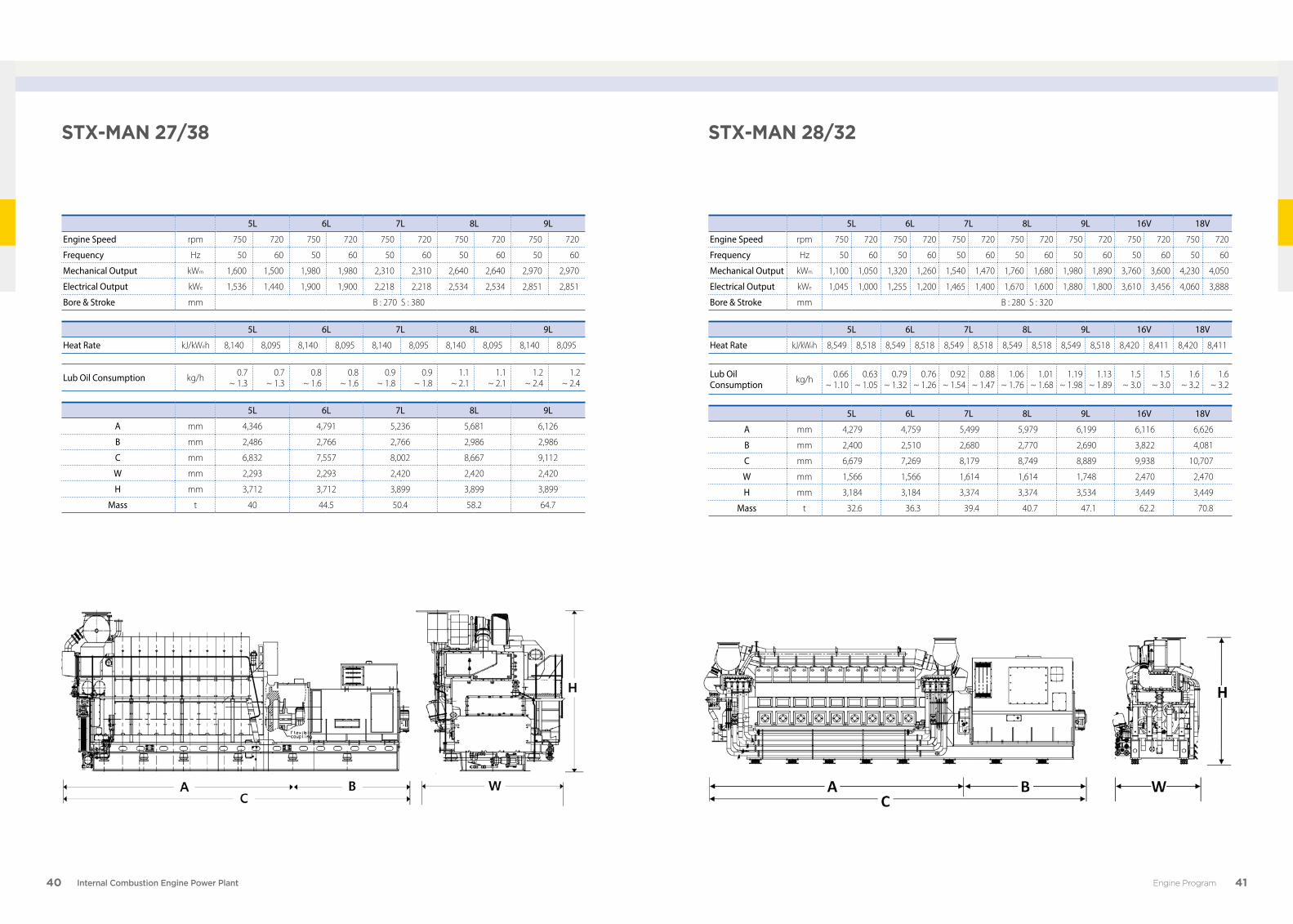
stX-man 27/38 stX-man 28/32
5L 6L 7L 8L 9L
Engine Speed rpm 750 720 750 720 750 720 750 720 750 720
Frequency Hz 50 60 50 60 50 60 50 60 50 60
Mechanical Output kWm 1,600 1,500 1,980 1,980 2,310 2,310 2,640 2,640 2,970 2,970
Electrical Output kWe 1,536 1,440 1,900 1,900 2,218 2,218 2,534 2,534 2,851 2,851
Bore & Stroke mm B : 270 S : 380
5L 6L 7L 8L 9L
Heat Rate kJ/kWeh 8,140 8,095 8,140 8,095 8,140 8,095 8,140 8,095 8,140 8,095
Lub Oil Consumption kg/h 0.7~ 1.3
0.7~ 1.3
0.8~ 1.6
0.8~ 1.6
0.9~ 1.8
0.9~ 1.8
1.1~ 2.1
1.1~ 2.1
1.2 ~ 2.4
1.2 ~ 2.4
5L 6L 7L 8L 9L
A mm 4,346 4,791 5,236 5,681 6,126
B mm 2,486 2,766 2,766 2,986 2,986
C mm 6,832 7,557 8,002 8,667 9,112
W mm 2,293 2,293 2,420 2,420 2,420
H mm 3,712 3,712 3,899 3,899 3,899
Mass t 40 44.5 50.4 58.2 64.7
5L 6L 7L 8L 9L 16V 18V
Engine Speed rpm 750 720 750 720 750 720 750 720 750 720 750 720 750 720
Frequency Hz 50 60 50 60 50 60 50 60 50 60 50 60 50 60
Mechanical Output kWm 1,100 1,050 1,320 1,260 1,540 1,470 1,760 1,680 1,980 1,890 3,760 3,600 4,230 4,050
Electrical Output kWe 1,045 1,000 1,255 1,200 1,465 1,400 1,670 1,600 1,880 1,800 3,610 3,456 4,060 3,888
Bore & Stroke mm B : 280 S : 320
5L 6L 7L 8L 9L 16V 18V
Heat Rate kJ/kWeh 8,549 8,518 8,549 8,518 8,549 8,518 8,549 8,518 8,549 8,518 8,420 8,411 8,420 8,411
Lub Oil Consumption kg/h 0.66
~ 1.100.63
~ 1.050.79
~ 1.320.76
~ 1.260.92
~ 1.540.88
~ 1.471.06
~ 1.761.01
~ 1.681.19
~ 1.981.13
~ 1.891.5
~ 3.01.5
~ 3.01.6
~ 3.21.6
~ 3.2
5L 6L 7L 8L 9L 16V 18V
A mm 4,279 4,759 5,499 5,979 6,199 6,116 6,626
B mm 2,400 2,510 2,680 2,770 2,690 3,822 4,081
C mm 6,679 7,269 8,179 8,749 8,889 9,938 10,707
W mm 1,566 1,566 1,614 1,614 1,748 2,470 2,470
H mm 3,184 3,184 3,374 3,374 3,534 3,449 3,449
Mass t 32.6 36.3 39.4 40.7 47.1 62.2 70.8
Engine Program
42 Internal Combustion Engine Power Plant 43
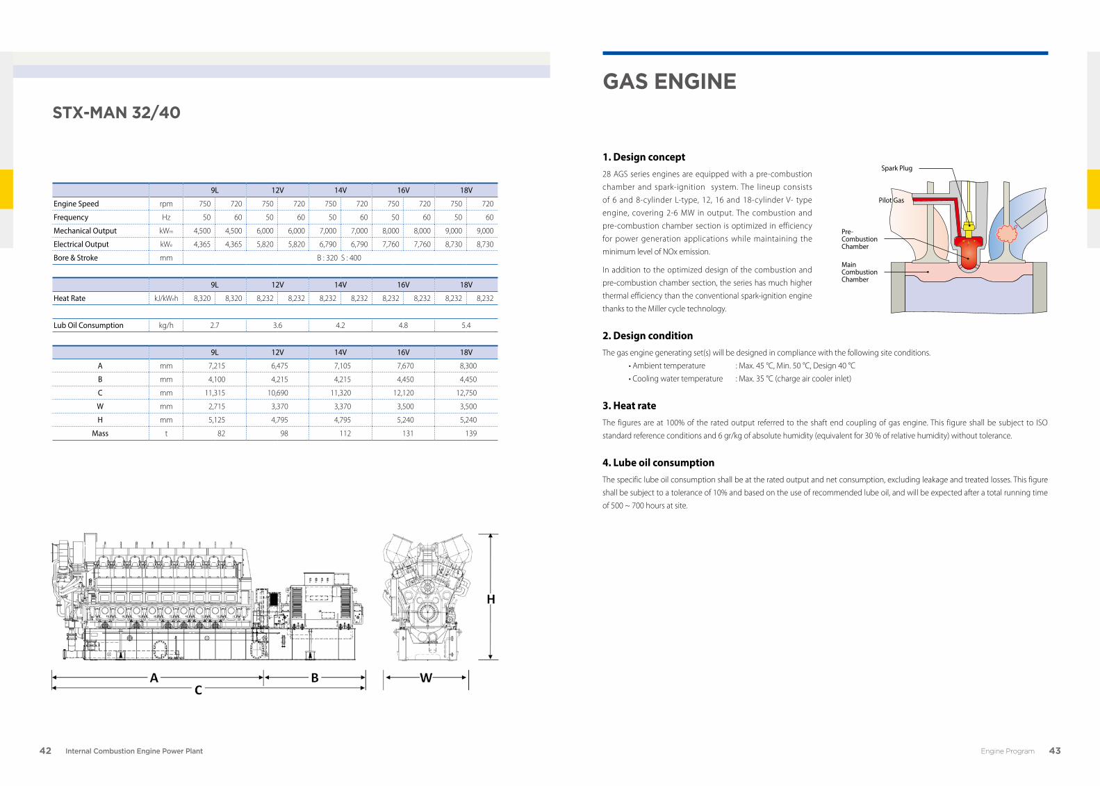
stX-man 32/40
9L 12V 14V 16V 18V
Engine Speed rpm 750 720 750 720 750 720 750 720 750 720
Frequency Hz 50 60 50 60 50 60 50 60 50 60
Mechanical Output kWm 4,500 4,500 6,000 6,000 7,000 7,000 8,000 8,000 9,000 9,000
Electrical Output kWe 4,365 4,365 5,820 5,820 6,790 6,790 7,760 7,760 8,730 8,730
Bore & Stroke mm B : 320 S : 400
9L 12V 14V 16V 18V
Heat Rate kJ/kWeh 8,320 8,320 8,232 8,232 8,232 8,232 8,232 8,232 8,232 8,232
Lub Oil Consumption kg/h 2.7 3.6 4.2 4.8 5.4
9L 12V 14V 16V 18V
A mm 7,215 6,475 7,105 7,670 8,300
B mm 4,100 4,215 4,215 4,450 4,450
C mm 11,315 10,690 11,320 12,120 12,750
W mm 2,715 3,370 3,370 3,500 3,500
H mm 5,125 4,795 4,795 5,240 5,240
Mass t 82 98 112 131 139
gas engIne
1. Design concept 28 AGS series engines are equipped with a pre-combustion
chamber and spark-ignition system. The lineup consists
of 6 and 8-cylinder L-type, 12, 16 and 18-cylinder V- type
engine, covering 2-6 MW in output. The combustion and
pre-combustion chamber section is optimized in efficiency
for power generation applications while maintaining the
minimum level of NOx emission.
In addition to the optimized design of the combustion and
pre-combustion chamber section, the series has much higher
thermal efficiency than the conventional spark-ignition engine
thanks to the Miller cycle technology.
2. Design conditionThe gas engine generating set(s) will be designed in compliance with the following site conditions.
• Ambient temperature : Max. 45 °C, Min. 50 °C, Design 40 °C
• Cooling water temperature : Max. 35 °C (charge air cooler inlet)
3. Heat rateThe figures are at 100% of the rated output referred to the shaft end coupling of gas engine. This figure shall be subject to ISO
standard reference conditions and 6 gr/kg of absolute humidity (equivalent for 30 % of relative humidity) without tolerance.
4. Lube oil consumption The specific lube oil consumption shall be at the rated output and net consumption, excluding leakage and treated losses. This figure
shall be subject to a tolerance of 10% and based on the use of recommended lube oil, and will be expected after a total running time
of 500 ~ 700 hours at site.
Pilot Gas
Spark Plug
Pre-Combustion Chamber
Main CombustionChamber
Engine Program

44 Internal Combustion Engine Power Plant 45
0 1,000
V28AGS
L28AGS
6,0005,0004,0003,0002,000
stX-nIIgata 28ags
6L 8L 12V 16V 18V
Engine Speed rpm 750 720 750 720 750 720 750 720 750 720
Frequency Hz 50 60 50 60 50 60 50 60 50 60
Mechanical Output kWm 2,083 1,959 2,760 2,629 4,124 3,918 5,464 5,258 6,186 5,928
Electrical Output kWe 2,000 1,900 2,650 2,550 4,000 3,800 5,300 5,100 6,000 5,750
Bore & Stroke mm B : 295 S : 400
6L 8L 12V 16V 18V
Heat Rate kJ/kWeh 7,901 7,901 7,884 7,884 7,651 7,651 7,618 7,618 7,585 7,585
Lub Oil Consumption kg/cyl.h 0.24 0.23 0.24 0.23 0.24 0.23 0.24 0.23 0.24 0.23
6L 8L 12V 16V 18V
A mm 5,130 6,265 6,070 7,130 7,660
B mm 2,910 2,910 3,080 3,080 3,080
C mm 8,040 9,175 9,150 10,210 10,740
W mm 3,000 3,000 3,600 3,600 3,600
H mm 4,000 4,000 4,600 4,600 4,600
Mass t 44.5 58 83 106 125
* The data of ‘mass’ include common bed weight.
Output RangeEngine Model
Output (kWe)
Engine Program

46 Internal Combustion Engine Power Plant 47
low sPeed engIne
1. Nominal rating (MCR)The engine ratings quoted remain valid up to tropical conditions:
• Blower inlet temperature : 45°C
• Blower inlet pressure : 1,000 mBar
• Charge air coolant temperature : 32°C
MCR (Maximum Continuous Rating) is defined as the maximum output (MW) that a generating station is capable of producing
continuously under normal conditions over a year. Under ideal conditions, the actual output could be higher than the MCR.
2. Engine output• kWm : Mechanical Power Output (Engine)
• kWe : Electrical Power Output (Engine + Alternator)
3. Site specified ratingL1 (Power optimized) > site specified rating > L2 (Fuel economy optimized)
The engine may be operated without restriction at any load up to site specified rating. Operating at overload rating, i.e. 110% of the
site specified rating, is permissible for one hour every 12 consecutive hours.
4. Engine heat rateThe figures specified in the table refer to Electrical output and to ISO 3046/1-2002 ambient conditions:
• Blower inlet temperature : 25°C
• Blower inlet pressure : 1,000 mBar
• Charge air coolant temperature : 25°C
5. Fuel oil consumption guarantee (MC-S engine)The MCR heat rate guaranteed by MAN Diesel & Turbo is subject to a tolerance of ±5% at ISO 3046/1-2002 ambient conditions and the
figures comply with World Bank guide line.
0 10,000 60,00050,00040,00030,00020,000
90MC-S
80MC-S
Output RangeEngine Model
Output (kWe)
Engine Program
48 Internal Combustion Engine Power Plant 49
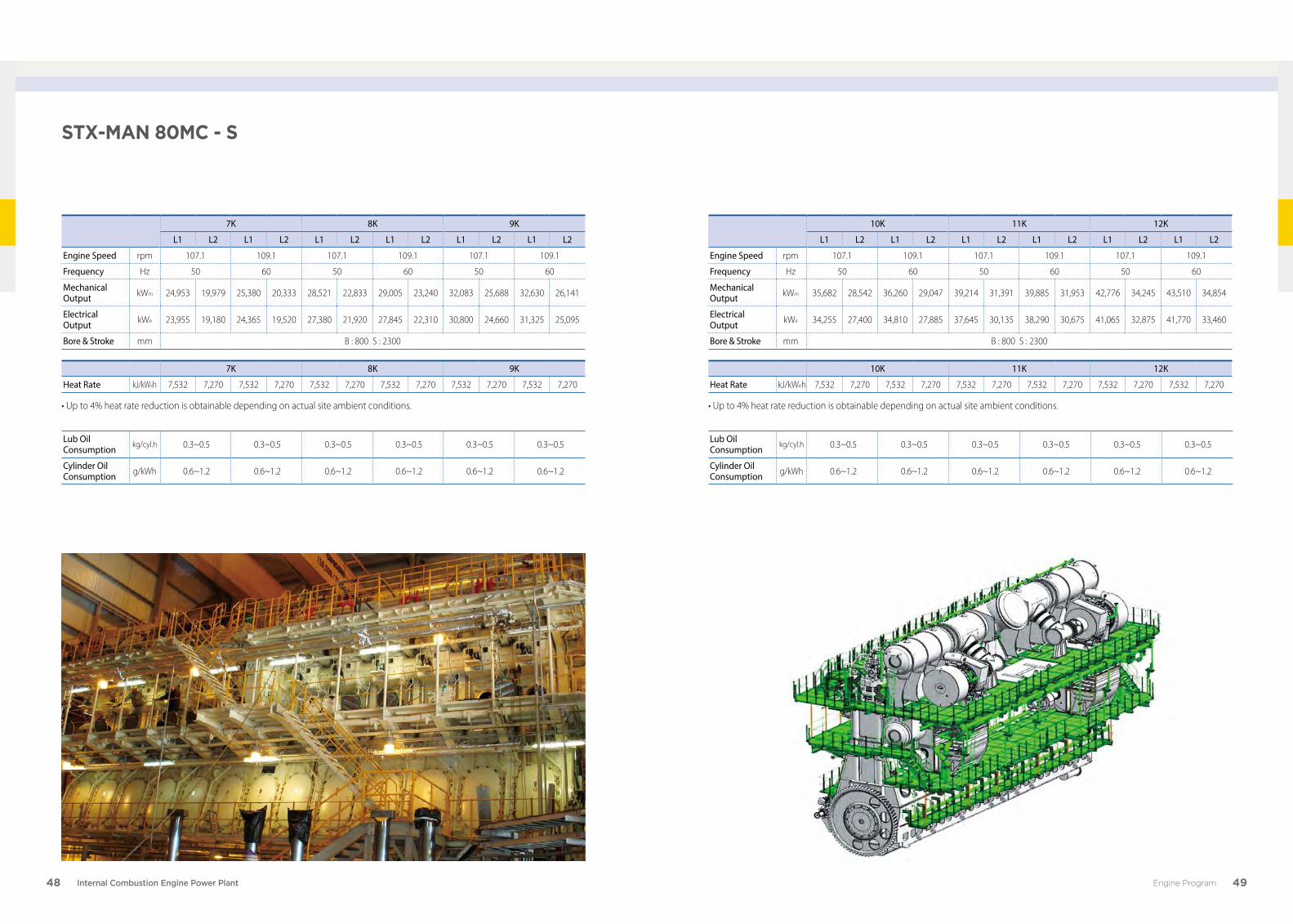
stX-man 80mC - s
7K 8K 9K
L1 L2 L1 L2 L1 L2 L1 L2 L1 L2 L1 L2
Engine Speed rpm 107.1 109.1 107.1 109.1 107.1 109.1
Frequency Hz 50 60 50 60 50 60
Mechanical Output kWm 24,953 19,979 25,380 20,333 28,521 22,833 29,005 23,240 32,083 25,688 32,630 26,141
Electrical Output kWe 23,955 19,180 24,365 19,520 27,380 21,920 27,845 22,310 30,800 24,660 31,325 25,095
Bore & Stroke mm B : 800 S : 2300
7K 8K 9K
Heat Rate kJ/kWeh 7,532 7,270 7,532 7,270 7,532 7,270 7,532 7,270 7,532 7,270 7,532 7,270
• Up to 4% heat rate reduction is obtainable depending on actual site ambient conditions.
Lub Oil Consumption kg/cyl.h 0.3~0.5 0.3~0.5 0.3~0.5 0.3~0.5 0.3~0.5 0.3~0.5
Cylinder Oil Consumption g/kWh 0.6~1.2 0.6~1.2 0.6~1.2 0.6~1.2 0.6~1.2 0.6~1.2
10K 11K 12K
L1 L2 L1 L2 L1 L2 L1 L2 L1 L2 L1 L2
Engine Speed rpm 107.1 109.1 107.1 109.1 107.1 109.1
Frequency Hz 50 60 50 60 50 60
Mechanical Output kWm 35,682 28,542 36,260 29,047 39,214 31,391 39,885 31,953 42,776 34,245 43,510 34,854
Electrical Output kWe 34,255 27,400 34,810 27,885 37,645 30,135 38,290 30,675 41,065 32,875 41,770 33,460
Bore & Stroke mm B : 800 S : 2300
10K 11K 12K
Heat Rate kJ/kWeh 7,532 7,270 7,532 7,270 7,532 7,270 7,532 7,270 7,532 7,270 7,532 7,270
• Up to 4% heat rate reduction is obtainable depending on actual site ambient conditions.
Lub Oil Consumption kg/cyl.h 0.3~0.5 0.3~0.5 0.3~0.5 0.3~0.5 0.3~0.5 0.3~0.5
Cylinder Oil Consumption g/kWh 0.6~1.2 0.6~1.2 0.6~1.2 0.6~1.2 0.6~1.2 0.6~1.2
Engine Program

50 Internal Combustion Engine Power Plant 51
stX-man 90mC - s
7K 8K 9K
L1 L2 L1 L2 L1 L2 L1 L2 L1 L2 L1 L2
Engine Speed rpm 107.1 109.1 107.1 109.1 107.1 109.1
Frequency Hz 50 60 50 60 50 60
Mechanical Output kWm 31,563 25,240 32,135 25,734 36,073 27,219 36,724 29,411 40,583 32,448 41,313 33,089
Electrical Output kWe 30,300 24,230 30,850 24,705 34,630 26,130 35,255 28,235 38,960 31,150 39,660 31,765
Bore & Stroke mm B : 900 S : 2300
7K 8K 9K
Heat Rate kJ/kWeh 7,532 7,270 7,532 7,270 7,532 7,270 7,532 7,270 7,532 7,270 7,532 7,270
• Up to 4% heat rate reduction is obtainable depending on actual site ambient conditions.
Lub Oil Consumption kg/cyl.h 0.3~0.6 0.3~0.6 0.3~0.6 0.3~0.6 0.3~0.6 0.3~0.6
Cylinder Oil Consumption g/kWh 0.6~1.2 0.6~1.2 0.6~1.2 0.6~1.2 0.6~1.2 0.6~1.2
10K 11K 12K
L1 L2 L1 L2 L1 L2 L1 L2 L1 L2 L1 L2
Engine Speed rpm 107.1 109.1 107.1 109.1 103.4 102.9
Frequency Hz 50 60 50 60 50 60
Mechanical Output kWm 45,094 36,052 45,906 36,766 49,604 39,661 50,495 40,443 52,284 41,803 52,041 41,559
Electrical Output kWe 43,290 34,610 44,070 35,295 47,620 38,075 48,475 38,825 50,193 40,131 49,959 39,897
Bore & Stroke mm B : 900 S : 2300
10K 11K 12K
Heat Rate kJ/kWeh 7,532 7,270 7,532 7,270 7,532 7,270 7,532 7,270 7,532 7,270 7,532 7,270
• Up to 4% heat rate reduction is obtainable depending on actual site ambient conditions.
Lub Oil Consumption kg/cyl.h 0.3~0.6 0.3~0.6 0.3~0.6 0.3~0.6 0.3~0.6 0.3~0.6
Cylinder Oil Consumption g/kWh 0.6~1.2 0.6~1.2 0.6~1.2 0.6~1.2 0.6~1.2 0.6~1.2
Engine Program
52 Internal Combustion Engine Power Plant 53
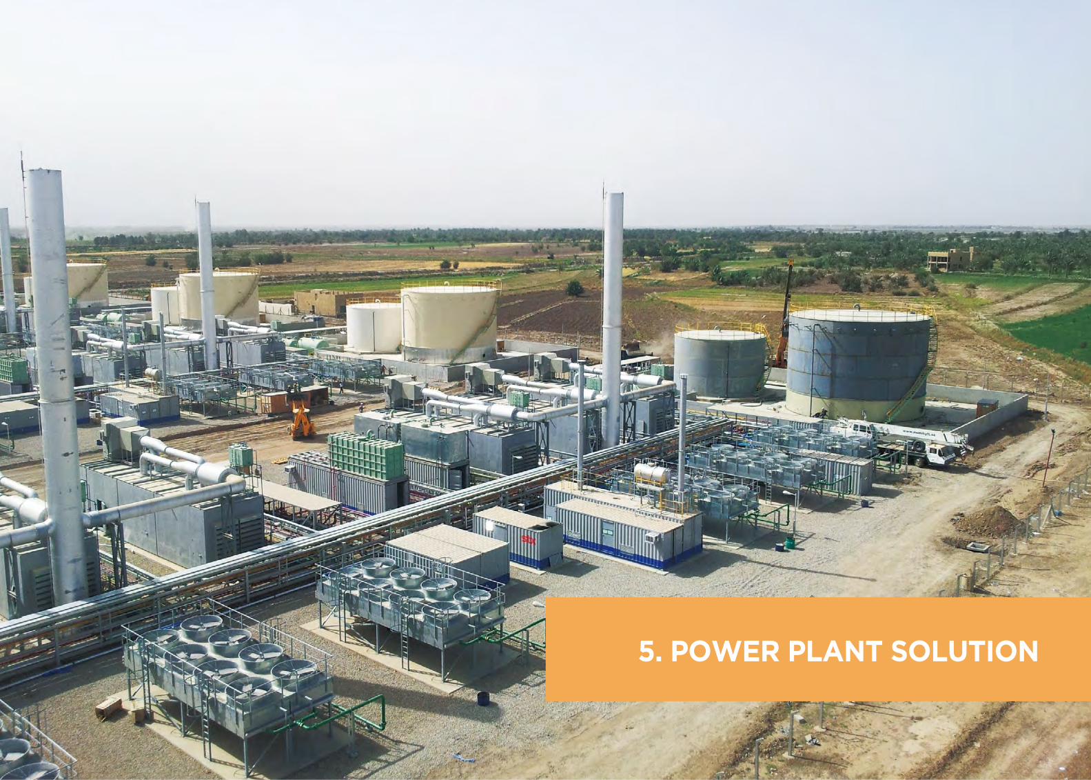
5. Power Plant solutIon
54 Internal Combustion Engine Power Plant 55Power Plant Solution
L.T Radiator H.T Radiator
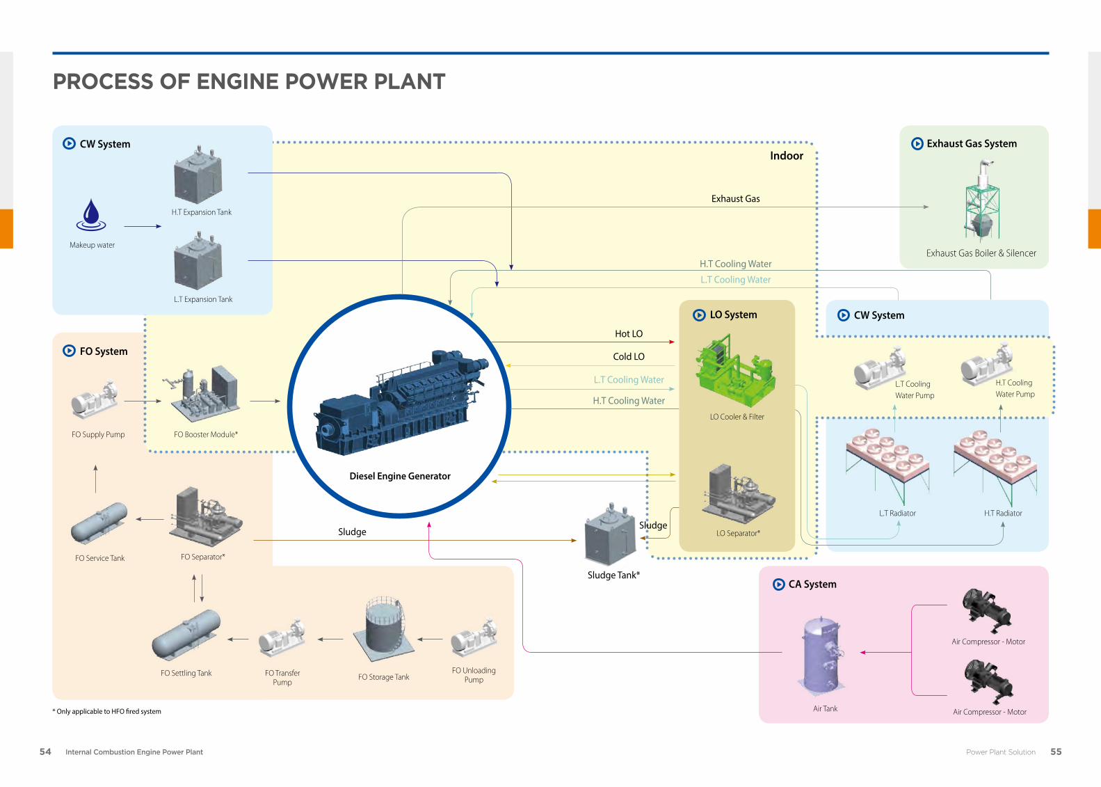
ProCess of engIne Power Plant
H.T Expansion Tank
FO Booster Module*
Sludge
Hot LO
Cold LO
Air Tank
Air Compressor - Motor
Air Compressor - Motor
FO System
CW System
* Only applicable to HFO fired system
IndoorExhaust Gas System
CW System
CA System
FO Service Tank FO Separator*
L.T Cooling Water Pump
L.T Cooling Water
H.T Cooling Water
Exhaust Gas
H.T Cooling Water
L.T Cooling Water
H.T Cooling Water Pump
Exhaust Gas Boiler & Silencer
FO Settling Tank FO Storage Tank
FO Supply Pump
FO Transfer Pump
FO Unloading Pump
L.T Expansion Tank
Makeup water
Diesel Engine Generator
Sludge
Sludge Tank*
LO System
LO Cooler & Filter
LO Separator*
56 Internal Combustion Engine Power Plant 57Power Plant Solution
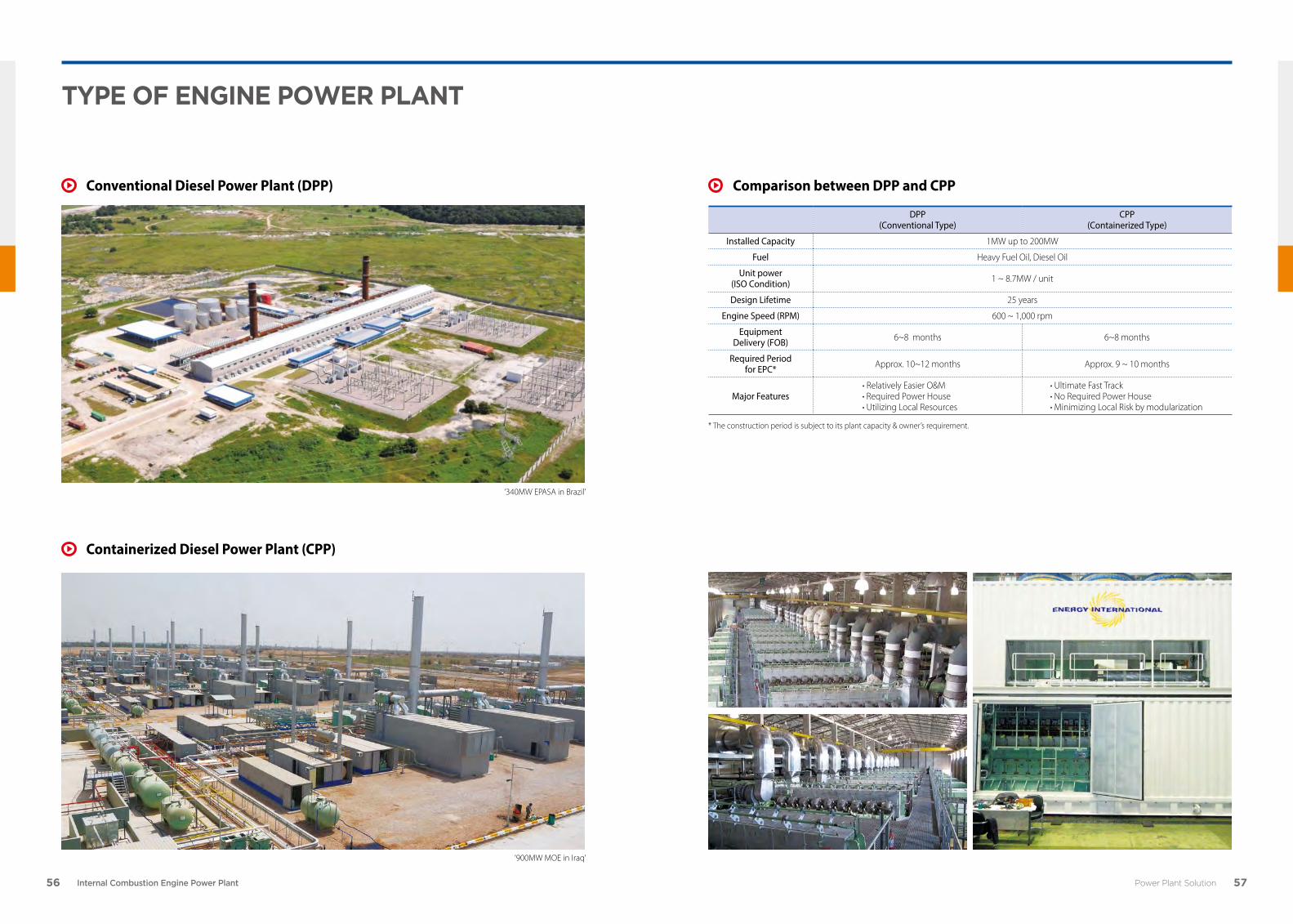
tyPe of engIne Power Plant
Conventional Diesel Power Plant (DPP)
Containerized Diesel Power Plant (CPP)
DPP (Conventional Type)
CPP (Containerized Type)
Installed Capacity 1MW up to 200MW
Fuel Heavy Fuel Oil, Diesel Oil
Unit power(ISO Condition) 1 ~ 8.7MW / unit
Design Lifetime 25 years
Engine Speed (RPM) 600 ~ 1,000 rpm
Equipment Delivery (FOB) 6~8 months 6~8 months
Required Period for EPC* Approx. 10~12 months Approx. 9 ~ 10 months
Major Features· Relatively Easier O&M· Required Power House· Utilizing Local Resources
· Ultimate Fast Track· No Required Power House· Minimizing Local Risk by modularization
Comparison between DPP and CPP
* The construction period is subject to its plant capacity & owner’s requirement.
‘340MW EPASA in Brazil’
‘900MW MOE in Iraq’

58 Internal Combustion Engine Power Plant 59Power Plant Solution
ConventIonal dIesel Power Plant(dPP)
1 Power House
1
2
3
6
7
41
2
8
9
10
5
34
Installation of D/G Sets Air Ventilation System Intake & Exhaust Gas System
2 Heat Recovery Boiler System3 Piping System4 Cooling System5 Internal Switch Gear Room6 Purifier & Pump House7 Tank Farm8 Transformer9 Outgoing Switch Gear Room
10 Substation & Transmission
60 Internal Combustion Engine Power Plant 61Power Plant Solution
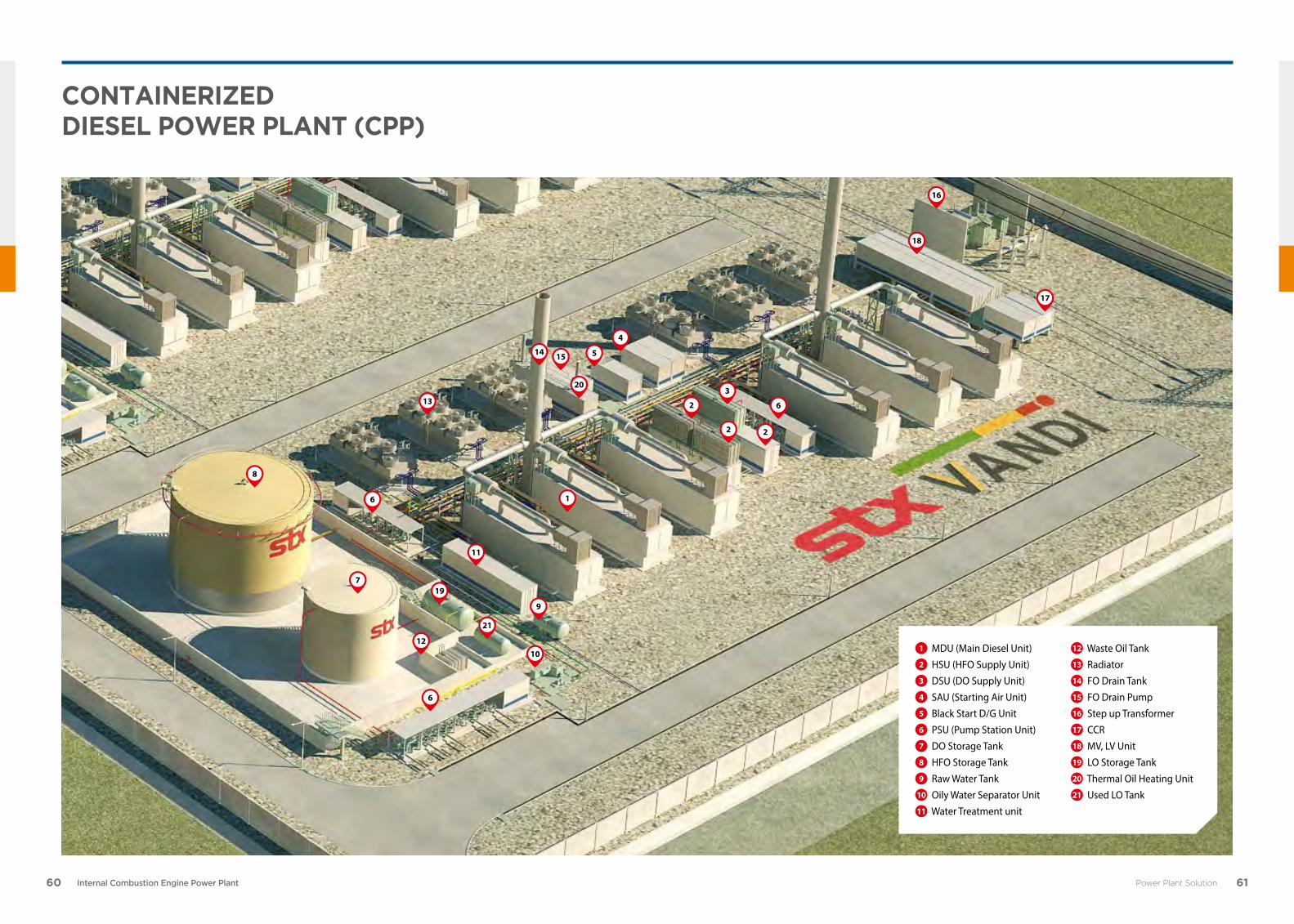
ContaInerIZed dIesel Power Plant (CPP)
12 Waste Oil Tank13 Radiator14 FO Drain Tank15 FO Drain Pump16 Step up Transformer17 CCR18 MV, LV Unit19 LO Storage Tank20 Thermal Oil Heating Unit21 Used LO Tank
1 MDU (Main Diesel Unit)2 HSU (HFO Supply Unit)3 DSU (DO Supply Unit)4 SAU (Starting Air Unit)5 Black Start D/G Unit6 PSU (Pump Station Unit)7 DO Storage Tank8 HFO Storage Tank9 Raw Water Tank
10 Oily Water Separator Unit11 Water Treatment unit
2
2 2
3
6
18
16
17
1
4
5
6
13
14 15
20
11
9
19
21
1012
6
7
8
62 Internal Combustion Engine Power Plant
ProjeCt basIC work sCoPe
Project Milestone
Basic Work Scope Split
• STX as EPC Provider can execute entire diesel power plant works (A,B) by international quality control system and local standards to meet local regulations.
Basic / Detailed Engineering
Equipment Supply
Training • Factory Training
Installation
Commissioning • Site Test & Commissioning
Commercial Operation • Completion • O&M
• Technical Specification for Diesel Power Plant• Estimated Total Power Demand• General Arrangement Drawing for Gen-set• General Layout for Power Plant• Electrical Panel Layout• Outline Drawings for Equipment• Piping and Instrumentation Diagram• Single Line Diagram
• Sequence Diagram for Panels• Control Logic Diagram• Instrument List• Design Data for Engineering of Equipment• Factory Test and Site Test Program• Piping Layout• Cable Layout including Cable Schedule Plan• Spare parts and Tool List
• Manufacturing• Assembly• Shop Test
• Shipping • Transport
• Basic Plant Engineering
• Diesel Engine Generators
• Plant Mechanical Auxiliaries
• Plant Electric Auxiliaries
• Commissioning, Supervision
• during erection period
• Authority Permits, License.
• Access Roads to Site
• Initial Fuel Oil, Lube Oil, Cooling Water,
Chemicals.
• Insurance, Import Duties, Taxation etc.
• Various Oil & Water Tanks
• Balance of Plant Equipment
• Transport (Ocean, Inland)
• Civil & Building Engineering &
Construction
• Erection of Plant Equipmen
Equipment (STX Scope)
Local Works (STX Leading)
Customer Works
A
B
C
• Civil Work• Installation
• Mechanical Work• Electrical Work
63Contacts
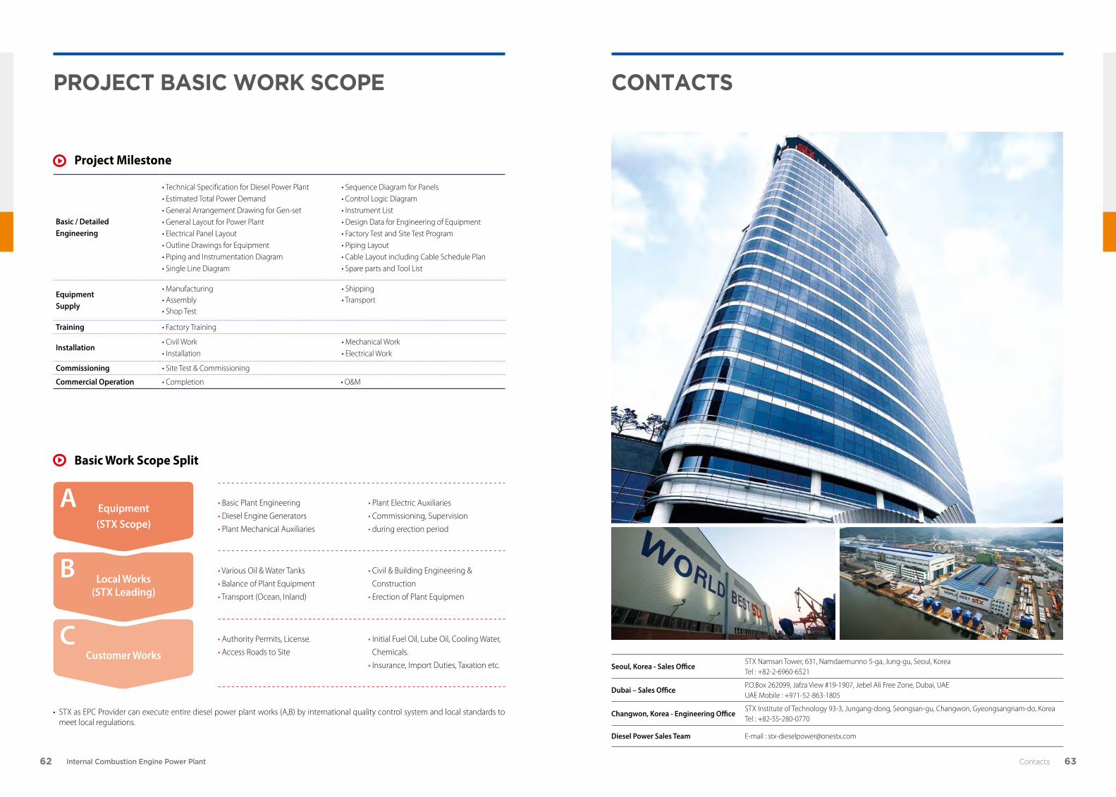
ContaCts
Seoul, Korea - Sales OfficeSTX Namsan Tower, 631, Namdaemunno 5-ga, Jung-gu, Seoul, Korea Tel : +82-2-6960-6521
Dubai – Sales OfficeP.O.Box 262099, Jafza View #19-1907, Jebel Ali Free Zone, Dubai, UAEUAE Mobile : +971-52-863-1805
Changwon, Korea - Engineering OfficeSTX Institute of Technology 93-3, Jungang-dong, Seongsan-gu, Changwon, Gyeongsangnam-do, KoreaTel : +82-55-280-0770
Diesel Power Sales Team E-mail : [email protected]

http:// www.stxhi.co.kr
This document is the product and property of STX Heavy Industries and is protected by applicable copyright laws.
Subject to modification in the interest of technical progress. Reproduction permitted provided source is given.