Embed Size (px)
Citation preview
MAC
HIN
E SA
FETY
INTERLOCK SWITCHES
More information online at bannerengineering.com584
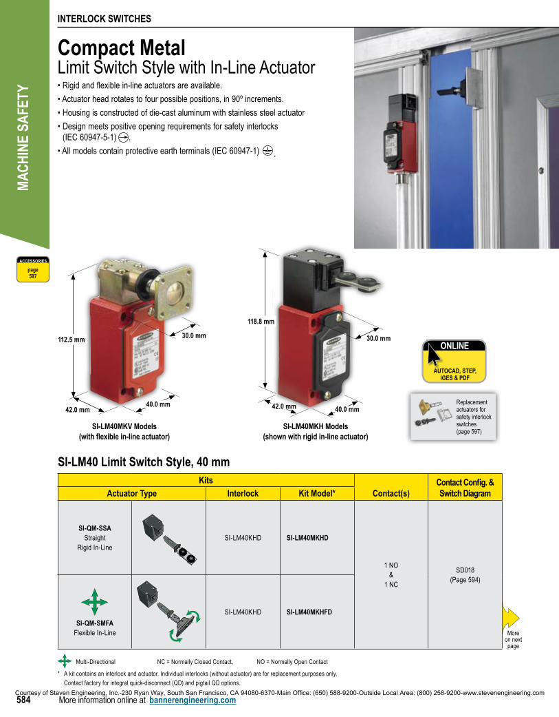
SI-LM40MKV Models(with flexible in-line actuator)
SI-LM40MKH Models(shown with rigid in-line actuator)
40.0 mm
112.5 mm
42.0 mm
Compact MetalLimit Switch Style with In-Line Actuator•Rigidandflexiblein-lineactuatorsareavailable.
•Actuatorheadrotatestofourpossiblepositions,in90ºincrements.
•Housingisconstructedofdie-castaluminumwithstainlesssteelactuator
•Designmeetspositiveopeningrequirementsforsafetyinterlocks (IEC 60947-5-1) .
•Allmodelscontainprotectiveearthterminals(IEC60947-1) .
ONLINE
AUTOCAD, STEP, IGES & PDF
ACCESSORIES
page597
SI-LM40 Limit Switch Style, 40 mmKits
Contact(s)Contact Config. & Switch DiagramActuator Type Interlock Kit Model*
SI-QM-SSAStraight
Rigid In-LineSI-LM40KHD SI-LM40MKHD
1 NO&
1 NC
SD018 (Page 594)
SI-QM-SMFAFlexible In-Line
SI-LM40KHD SI-LM40MKHFD
Moreon next page
Multi-Directional NC = Normally Closed Contact, NO = Normally Open Contact
* A kit contains an interlock and actuator. Individual interlocks (without actuator) are for replacement purposes only.
Contact factory for integral quick-disconnect (QD) and pigtail QD options.
42.0 mm 40.0 mm
118.8 mm
30.0 mm30.0 mm
Replacement actuators for safety interlock switches(page 597)
Courtesy of Steven Engineering, Inc.-230 Ryan Way, South San Francisco, CA 94080-6370-Main Office: (650) 588-9200-Outside Local Area: (800) 258-9200-www.stevenengineering.com
INTERLOCK SWITCHES
FIBER OPTIC
MAGNET
HINGE
COMPACT PLASTIC
COMPACT METAL
LOCKING STYLE
585
PhotoelectricsSensors
Fiber OpticSensors
Special PurposeSensors
Measurement & Inspection Sensors
Vision
Wireless
Lighting &Indicators
Safety Light Screens
Safety Laser Scanners
Fiber OpticSafety Systems
Safety Controllers & Modules
Safety Two-Hand Control Modules
Safety Interlock Switches
Emergency Stop & Stop Control
More information online at bannerengineering.com
ACCESSORIES
page597
SI-LM40 Limit Switch Style, 40 mmKits
Contact(s)Contact Config. & Switch DiagramActuator Type Interlock Kit Model*
SI-QM-SSAStraight
Rigid In-LineSI-LM40KHE SI-LM40MKHE
2 NCSD019
(Page 595)
SI-QM-SMFAFlexible In-Line
SI-LM40KHE SI-LM40MKHFE
SI-QM-SSAStraight
Rigid In-LineSI-LM40KHF SI-LM40MKHF
2 NC&
1 NO
SD020 (Page 595)
SI-QM-SMFAFlexible In-Line
SI-LM40KHF SI-LM40MKHFF
SI-QM-90AFlexible In-Line
SI-LM40KVD SI-LM40MKVD1 NO
&1 NC
SD021 (Page 595)
SI-LM40KVE SI-LM40MKVE 2 NCSD022
(Page 595)
Multi-Directional NC = Normally Closed Contact, NO = Normally Open Contact
* A kit contains an interlock and actuator. Individual interlocks (without actuator) are for replacement purposes only.
Contact factory for integral quick-disconnect (QD) and pigtail QD options.
(cont’d)
Courtesy of Steven Engineering, Inc.-230 Ryan Way, South San Francisco, CA 94080-6370-Main Office: (650) 588-9200-Outside Local Area: (800) 258-9200-www.stevenengineering.com
MAC
HIN
E SA
FETY
INTERLOCK SWITCHES
More information online at bannerengineering.com586
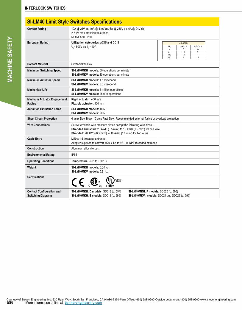
SI-LM40 Limit Style Switches SpecificationsContact Rating 10A @ 24V ac, 10A @ 110V ac, 6A @ 230V ac, 6A @ 24V dc
2.5 kV max. transient toleranceNEMA A300 P300
European Rating Utilization categories: AC15 and DC13U
i= 500V ac, I
th= 10A
40-60 HzU
e
V Ie/AC-15
AIe/DC-13
A24 10 6110 10 1230 6 .4
Contact Material Silver-nickel alloy
Maximum Switching Speed SI-LM40MKH models: 50 operations per minuteSI-LM40MKV models: 10 operations per minute
Maximum Actuator Speed SI-LM40MKH models: 1.5 m/secondSI-LM40MKV models: 0.5 m/second
Mechanical Life SI-LM40MKH models: 1 million operationsSI-LM40MKV models: 25,000 operations
Minimum Actuator Engagement Radius
Rigid actuator: 400 mmFlexible actuator: 150 mm
Actuation Extraction Force SI-LM40MKH models: 10 NSI-LM40MKV models: 20 N
Short Circuit Protection 6 amp Slow Blow, 10 amp Fast Blow. Recommended external fusing or overload protection.
Wire Connections Screw terminals with pressure plates accept the following wire sizes –Stranded and solid: 20 AWG (0.5 mm2) to 16 AWG (1.5 mm2) for one wireStranded: 20 AWG (0.5 mm2) to 18 AWG (1.0 mm2) for two wires
Cable Entry M20 x 1.5 threaded entranceAdapter supplied to convert M20 x 1.5 to ½" - 14 NPT threaded entrance
Construction Aluminum alloy die cast
Environmental Rating IP65
Operating Conditions Temperature: -30° to +80° C
Weight SI-LM40MKH models: 0.34 kgSI-LM40MKV models: 0.31 kg
Certifications
AUXILIARYDEVICE
Contact Configuration and Switching Diagrams
SI-LM40MKH..D models: SD018 (p. 594) SI-LM40MKH..F models: SD020 (p. 595)SI-LM40MKH..E models: SD019 (p. 595) SI-LM40MKV.. models: SD021 and SD022 (p. 595)
Courtesy of Steven Engineering, Inc.-230 Ryan Way, South San Francisco, CA 94080-6370-Main Office: (650) 588-9200-Outside Local Area: (800) 258-9200-www.stevenengineering.com
MAC
HIN
E SA
FETY
INTERLOCK SWITCHES
More information online at bannerengineering.com594
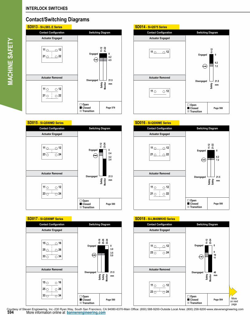
SD014 - SI-QS75 Series
Contact Configuration Switching Diagram
Actuator Engaged
6.2
0
11-1
2
7.2
21.5
mm
Engaged
Disengaged
Safe
ty
11 12
Actuator Removed
11 12
Open Closed Transition
Page 580
SD013 - SI-LS83..E Series
Contact Configuration Switching Diagram
Actuator Engaged
4.54.20
21.5
mm
Engaged
Disengaged
Safe
tyM
onito
r
11-1
2
21-2
2
21 22
11 12
Actuator Removed
21 22
11 12
Open Closed Transition
Page 579
SD017 - SI-QS90MF Series
Contact Configuration Switching Diagram
Actuator Engaged
3.0
3.5
0
15-1
6
25-2
6
33-3
4
5.0
21.5
mm
Engaged
Disengaged
Safe
tySa
fety
Mon
itor
25 26
33 34
15 16
Actuator Removed
25 26
33 34
15 16
Open Closed Transition
Page 580
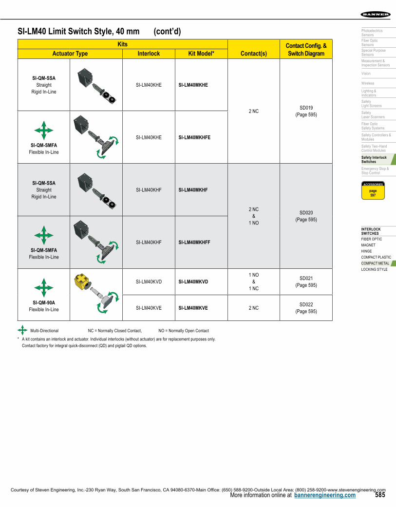
SD018 - SI-LM40MKHD Series
Contact Configuration Switching Diagram
Actuator Engaged
9
0
10
40
Engaged
Disengaged
11-1
2
23-2
4
Safe
ty
Mon
itor mm
11
23 24
11 12
Actuator Removed
23 24
11 12
Open Closed Transition
Page 584
SD016 - SI-QS90ME Series
Contact Configuration Switching Diagram
Actuator Engaged
6.2
0
11-1
2
21-2
2
7.2
21.5
mm
Engaged
Disengaged
Safe
tySa
fety
21 22
11 12
Actuator Removed
21 22
11 12
Open Closed Transition
Page 580
SD015 - SI-QS90MD Series
Contact Configuration Switching Diagram
Actuator Engaged
2.4
3.2
0
3.4
21.5
mm
Engaged
Disengaged
Safe
ty
Mon
itor
11-1
2
23-2
4
23 24
11 12
Actuator Removed
23 24
11 12
Open Closed Transition
Page 580
Contact/Switching Diagrams
Moreon next page
Courtesy of Steven Engineering, Inc.-230 Ryan Way, South San Francisco, CA 94080-6370-Main Office: (650) 588-9200-Outside Local Area: (800) 258-9200-www.stevenengineering.com
INTERLOCK SWITCHES
FIBER OPTIC
MAGNET
HINGE
COMPACT PLASTIC
COMPACT METAL
LOCKING STYLE
595
PhotoelectricsSensors
Fiber OpticSensors
Special PurposeSensors
Measurement & Inspection Sensors
Vision
Wireless
Lighting &Indicators
Safety Light Screens
Safety Laser Scanners
Fiber OpticSafety Systems
Safety Controllers & Modules
Safety Two-Hand Control Modules
Safety Interlock Switches
Emergency Stop & Stop Control
More information online at bannerengineering.com
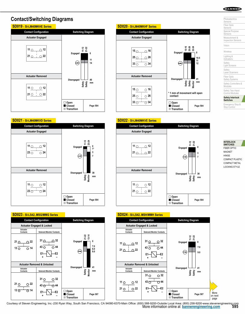
SD020 - SI-LM40MKHF Series
Contact Configuration Switching Diagram
Actuator Engaged
10.5
0
11
41
Engaged
Disengaged
15-1
6
25-2
6
Safe
ty
Safe
ty
33-3
4M
onito
r mm
12
25 26
33 34
15 16
Actuator Removed
25 26
33 34
15 16
Open Closed Transition
Page 584
SD019 - SI-LM40MKHE Series
Contact Configuration Switching Diagram
Actuator Engaged
11
0
14
40
Engaged
Disengaged11
-12
21-2
2Sa
fety
Safe
ty mm
21 22
11 12
Actuator Removed
21 22
11 12
Open Closed Transition
Page 584
SD023 - SI-LS42..MSG/MMG Series
Contact Configuration Switching Diagram
Actuator Engaged & Locked
0
7.08.09.0
41
mm
Engaged
Disengaged
21-2
2
13-1
4
Safe
ty
Mon
itor
ActuatorContacts Solenoid Monitor Contacts
13 14
21 22
43 44
31 32
E1 E2+ –
Actuator Removed & UnlockedActuatorContacts Solenoid Monitor Contacts
13 14
21 22 43 44
31 32
E1 E2+ –
Open Closed Transition
Page 587
SD024 - SI-LS42..MSH/MMH Series
Contact Configuration Switching Diagram
Actuator Engaged & Locked
0
41
mm
Engaged
Disengaged
11-1
2
21-2
2
Safe
ty
Safe
ty
7.0
9.0
ActuatorContacts Solenoid Monitor Contacts
21 22
11 12
43 44
31 32
E1 E2+ –
Actuator Removed & UnlockedActuatorContacts Solenoid Monitor Contacts
21 22
11 12 43 44
31 32
E1 E2+ – Open
Closed Transition
Page 587
SD022 - SI-LM40MKVE Series
Contact Configuration Switching Diagram
Actuator Engaged
3
0
7
38
mm
Engaged
Disengaged
11-1
2
21-2
2
Safe
ty
Safe
ty
21 22
11 12
Actuator Removed
21 22
11 12
Open Closed Transition
Page 584
SD021 - SI-LM40MKVD Series
Contact Configuration Switching Diagram
Actuator Engaged
31*0
7
38
mm
Engaged
Disengaged
11-1
2
23-2
4
Safe
ty
Mon
itor
23 24
11 12
Actuator Removed
23 24
11 12
Open Closed Transition
Page 584
* 1 mm of movement will open contact
Contact/Switching Diagrams
Moreon next page
Courtesy of Steven Engineering, Inc.-230 Ryan Way, South San Francisco, CA 94080-6370-Main Office: (650) 588-9200-Outside Local Area: (800) 258-9200-www.stevenengineering.com